EP2891791A1 - Antriebssystem, insbesondere für eine selbstfahrende Baumaschine, insbesondere Bodenverdichter - Google Patents
Antriebssystem, insbesondere für eine selbstfahrende Baumaschine, insbesondere Bodenverdichter Download PDFInfo
- Publication number
- EP2891791A1 EP2891791A1 EP14193125.3A EP14193125A EP2891791A1 EP 2891791 A1 EP2891791 A1 EP 2891791A1 EP 14193125 A EP14193125 A EP 14193125A EP 2891791 A1 EP2891791 A1 EP 2891791A1
- Authority
- EP
- European Patent Office
- Prior art keywords
- drive
- hydraulic
- unit
- hydraulic pump
- motor assembly
- Prior art date
- Legal status (The legal status is an assumption and is not a legal conclusion. Google has not performed a legal analysis and makes no representation as to the accuracy of the status listed.)
- Granted
Links
Images

Classifications
-
- B—PERFORMING OPERATIONS; TRANSPORTING
- B60—VEHICLES IN GENERAL
- B60K—ARRANGEMENT OR MOUNTING OF PROPULSION UNITS OR OF TRANSMISSIONS IN VEHICLES; ARRANGEMENT OR MOUNTING OF PLURAL DIVERSE PRIME-MOVERS IN VEHICLES; AUXILIARY DRIVES FOR VEHICLES; INSTRUMENTATION OR DASHBOARDS FOR VEHICLES; ARRANGEMENTS IN CONNECTION WITH COOLING, AIR INTAKE, GAS EXHAUST OR FUEL SUPPLY OF PROPULSION UNITS IN VEHICLES
- B60K6/00—Arrangement or mounting of plural diverse prime-movers for mutual or common propulsion, e.g. hybrid propulsion systems comprising electric motors and internal combustion engines
- B60K6/08—Prime-movers comprising combustion engines and mechanical or fluid energy storing means
- B60K6/12—Prime-movers comprising combustion engines and mechanical or fluid energy storing means by means of a chargeable fluidic accumulator
-
- E—FIXED CONSTRUCTIONS
- E02—HYDRAULIC ENGINEERING; FOUNDATIONS; SOIL SHIFTING
- E02F—DREDGING; SOIL-SHIFTING
- E02F9/00—Component parts of dredgers or soil-shifting machines, not restricted to one of the kinds covered by groups E02F3/00 - E02F7/00
- E02F9/20—Drives; Control devices
- E02F9/22—Hydraulic or pneumatic drives
- E02F9/2217—Hydraulic or pneumatic drives with energy recovery arrangements, e.g. using accumulators, flywheels
-
- E—FIXED CONSTRUCTIONS
- E02—HYDRAULIC ENGINEERING; FOUNDATIONS; SOIL SHIFTING
- E02F—DREDGING; SOIL-SHIFTING
- E02F9/00—Component parts of dredgers or soil-shifting machines, not restricted to one of the kinds covered by groups E02F3/00 - E02F7/00
- E02F9/20—Drives; Control devices
- E02F9/22—Hydraulic or pneumatic drives
- E02F9/2278—Hydraulic circuits
- E02F9/2292—Systems with two or more pumps
-
- E—FIXED CONSTRUCTIONS
- E02—HYDRAULIC ENGINEERING; FOUNDATIONS; SOIL SHIFTING
- E02F—DREDGING; SOIL-SHIFTING
- E02F9/00—Component parts of dredgers or soil-shifting machines, not restricted to one of the kinds covered by groups E02F3/00 - E02F7/00
- E02F9/20—Drives; Control devices
- E02F9/22—Hydraulic or pneumatic drives
- E02F9/2278—Hydraulic circuits
- E02F9/2296—Systems with a variable displacement pump
-
- F—MECHANICAL ENGINEERING; LIGHTING; HEATING; WEAPONS; BLASTING
- F02—COMBUSTION ENGINES; HOT-GAS OR COMBUSTION-PRODUCT ENGINE PLANTS
- F02N—STARTING OF COMBUSTION ENGINES; STARTING AIDS FOR SUCH ENGINES, NOT OTHERWISE PROVIDED FOR
- F02N7/00—Starting apparatus having fluid-driven auxiliary engines or apparatus
-
- F—MECHANICAL ENGINEERING; LIGHTING; HEATING; WEAPONS; BLASTING
- F15—FLUID-PRESSURE ACTUATORS; HYDRAULICS OR PNEUMATICS IN GENERAL
- F15B—SYSTEMS ACTING BY MEANS OF FLUIDS IN GENERAL; FLUID-PRESSURE ACTUATORS, e.g. SERVOMOTORS; DETAILS OF FLUID-PRESSURE SYSTEMS, NOT OTHERWISE PROVIDED FOR
- F15B1/00—Installations or systems with accumulators; Supply reservoir or sump assemblies
- F15B1/02—Installations or systems with accumulators
- F15B1/024—Installations or systems with accumulators used as a supplementary power source, e.g. to store energy in idle periods to balance pump load
-
- F—MECHANICAL ENGINEERING; LIGHTING; HEATING; WEAPONS; BLASTING
- F15—FLUID-PRESSURE ACTUATORS; HYDRAULICS OR PNEUMATICS IN GENERAL
- F15B—SYSTEMS ACTING BY MEANS OF FLUIDS IN GENERAL; FLUID-PRESSURE ACTUATORS, e.g. SERVOMOTORS; DETAILS OF FLUID-PRESSURE SYSTEMS, NOT OTHERWISE PROVIDED FOR
- F15B21/00—Common features of fluid actuator systems; Fluid-pressure actuator systems or details thereof, not covered by any other group of this subclass
- F15B21/14—Energy-recuperation means
-
- B—PERFORMING OPERATIONS; TRANSPORTING
- B60—VEHICLES IN GENERAL
- B60K—ARRANGEMENT OR MOUNTING OF PROPULSION UNITS OR OF TRANSMISSIONS IN VEHICLES; ARRANGEMENT OR MOUNTING OF PLURAL DIVERSE PRIME-MOVERS IN VEHICLES; AUXILIARY DRIVES FOR VEHICLES; INSTRUMENTATION OR DASHBOARDS FOR VEHICLES; ARRANGEMENTS IN CONNECTION WITH COOLING, AIR INTAKE, GAS EXHAUST OR FUEL SUPPLY OF PROPULSION UNITS IN VEHICLES
- B60K6/00—Arrangement or mounting of plural diverse prime-movers for mutual or common propulsion, e.g. hybrid propulsion systems comprising electric motors and internal combustion engines
- B60K6/08—Prime-movers comprising combustion engines and mechanical or fluid energy storing means
- B60K6/12—Prime-movers comprising combustion engines and mechanical or fluid energy storing means by means of a chargeable fluidic accumulator
- B60K2006/123—Prime-movers comprising combustion engines and mechanical or fluid energy storing means by means of a chargeable fluidic accumulator for driving pneumatic motors
-
- B—PERFORMING OPERATIONS; TRANSPORTING
- B60—VEHICLES IN GENERAL
- B60K—ARRANGEMENT OR MOUNTING OF PROPULSION UNITS OR OF TRANSMISSIONS IN VEHICLES; ARRANGEMENT OR MOUNTING OF PLURAL DIVERSE PRIME-MOVERS IN VEHICLES; AUXILIARY DRIVES FOR VEHICLES; INSTRUMENTATION OR DASHBOARDS FOR VEHICLES; ARRANGEMENTS IN CONNECTION WITH COOLING, AIR INTAKE, GAS EXHAUST OR FUEL SUPPLY OF PROPULSION UNITS IN VEHICLES
- B60K6/00—Arrangement or mounting of plural diverse prime-movers for mutual or common propulsion, e.g. hybrid propulsion systems comprising electric motors and internal combustion engines
- B60K6/08—Prime-movers comprising combustion engines and mechanical or fluid energy storing means
- B60K6/12—Prime-movers comprising combustion engines and mechanical or fluid energy storing means by means of a chargeable fluidic accumulator
- B60K2006/126—Prime-movers comprising combustion engines and mechanical or fluid energy storing means by means of a chargeable fluidic accumulator the hydraulic accumulator starts the engine
-
- B—PERFORMING OPERATIONS; TRANSPORTING
- B60—VEHICLES IN GENERAL
- B60W—CONJOINT CONTROL OF VEHICLE SUB-UNITS OF DIFFERENT TYPE OR DIFFERENT FUNCTION; CONTROL SYSTEMS SPECIALLY ADAPTED FOR HYBRID VEHICLES; ROAD VEHICLE DRIVE CONTROL SYSTEMS FOR PURPOSES NOT RELATED TO THE CONTROL OF A PARTICULAR SUB-UNIT
- B60W2300/00—Indexing codes relating to the type of vehicle
- B60W2300/17—Construction vehicles, e.g. graders, excavators
-
- F—MECHANICAL ENGINEERING; LIGHTING; HEATING; WEAPONS; BLASTING
- F02—COMBUSTION ENGINES; HOT-GAS OR COMBUSTION-PRODUCT ENGINE PLANTS
- F02N—STARTING OF COMBUSTION ENGINES; STARTING AIDS FOR SUCH ENGINES, NOT OTHERWISE PROVIDED FOR
- F02N2300/00—Control related aspects of engine starting
- F02N2300/10—Control related aspects of engine starting characterised by the control output, i.e. means or parameters used as a control output or target
- F02N2300/102—Control of the starter motor speed; Control of the engine speed during cranking
-
- F—MECHANICAL ENGINEERING; LIGHTING; HEATING; WEAPONS; BLASTING
- F15—FLUID-PRESSURE ACTUATORS; HYDRAULICS OR PNEUMATICS IN GENERAL
- F15B—SYSTEMS ACTING BY MEANS OF FLUIDS IN GENERAL; FLUID-PRESSURE ACTUATORS, e.g. SERVOMOTORS; DETAILS OF FLUID-PRESSURE SYSTEMS, NOT OTHERWISE PROVIDED FOR
- F15B2211/00—Circuits for servomotor systems
- F15B2211/20—Fluid pressure source, e.g. accumulator or variable axial piston pump
- F15B2211/205—Systems with pumps
- F15B2211/2053—Type of pump
- F15B2211/20569—Type of pump capable of working as pump and motor
-
- F—MECHANICAL ENGINEERING; LIGHTING; HEATING; WEAPONS; BLASTING
- F15—FLUID-PRESSURE ACTUATORS; HYDRAULICS OR PNEUMATICS IN GENERAL
- F15B—SYSTEMS ACTING BY MEANS OF FLUIDS IN GENERAL; FLUID-PRESSURE ACTUATORS, e.g. SERVOMOTORS; DETAILS OF FLUID-PRESSURE SYSTEMS, NOT OTHERWISE PROVIDED FOR
- F15B2211/00—Circuits for servomotor systems
- F15B2211/80—Other types of control related to particular problems or conditions
- F15B2211/88—Control measures for saving energy
-
- Y—GENERAL TAGGING OF NEW TECHNOLOGICAL DEVELOPMENTS; GENERAL TAGGING OF CROSS-SECTIONAL TECHNOLOGIES SPANNING OVER SEVERAL SECTIONS OF THE IPC; TECHNICAL SUBJECTS COVERED BY FORMER USPC CROSS-REFERENCE ART COLLECTIONS [XRACs] AND DIGESTS
- Y02—TECHNOLOGIES OR APPLICATIONS FOR MITIGATION OR ADAPTATION AGAINST CLIMATE CHANGE
- Y02T—CLIMATE CHANGE MITIGATION TECHNOLOGIES RELATED TO TRANSPORTATION
- Y02T10/00—Road transport of goods or passengers
- Y02T10/60—Other road transportation technologies with climate change mitigation effect
- Y02T10/62—Hybrid vehicles
Definitions
- Such a drive system is from the WO 2013 / 074164A1 known as a drive system designed as a wheel loader construction machine.
- a drive unit is drivingly coupled via a gear arrangement with various hydraulic circuits.
- These hydraulic circuits comprise a hydraulic drive circuit with a hydraulic drive pump driven by the drive unit and a hydraulic drive motor driven by the flowing fluid during operation of the hydraulic drive pump for driving the drive wheels of the wheel loader.
- one or more hydraulic working circuits are provided. These also each comprise a driven by the drive unit via the gear assembly hydraulic working pump. By the through these pumps generated hydraulic pressure can be activated, for example, piston / cylinder units to move a blade in the working operation of the wheel loader.
- This drive system further includes a hydraulic drive assist unit.
- the hydraulic pump / motor assembly of this hydraulic drive assist unit can also be operated as a hydraulic motor to generate a relaxation of the pressure in the pressure fluid reservoir torque, which via the gear assembly to the various hydraulic circuits, so the hydraulic drive circuit and the the hydraulic working circuits can be transmitted.
- the hydraulic drive assisting unit may thus provide a drive assisting torque.
- hydraulic pump / motor assembly is operable in a cranking operation as a motor for starting the drive unit.
- the hydraulic pump / motor assembly As a motor for starting the drive unit, it is possible to use the hydraulic drive assist unit in a further operating state, ie the starting operating state. This relieves other system areas, such as a generally provided in association with the drive unit, electrically operated starter and allows the other hand, the temporary energy-saving shutdown of the drive unit, if this is not required for generating a drive torque, for example, during temporary parking equipped with such a drive system construction machine becomes.
- the hydraulic drive assistance unit has a starting valve unit for selectively enabling / interrupting a flow connection between at least one pressure fluid reservoir and the hydraulic pump / motor assembly at least in FIG Flow direction from the pressure fluid reservoir to the hydraulic pump / motor assembly includes.
- This starting valve can thus be designed specifically for the volume flows required for starting, can be designed in particular to set the volume flow and defined to ensure that by the hydraulic pump / motor assembly in the cranking state only for the starting of the power plant required drive assist torque is provided.
- a defined setting of the torque required for starting the drive unit can be obtained in a simple manner in that the starting valve unit comprises a proportional valve.
- the defined loading or unloading of a pressure fluid reservoir for receiving pressurized fluid may be obtained by the hydraulic drive assist unit including a charge / discharge valve unit for selectively enabling / disabling fluid communication between the hydraulic pump / motor assembly and at least a pressure fluid reservoir at least in the direction of flow from the pressure fluid reservoir to the hydraulic pump / motor assembly and comprises an expansion valve unit for selectively enabling / interrupting a flow connection between at least one pressure fluid reservoir and a fluid reservoir at least in the flow direction from the pressure fluid reservoir to the fluid reservoir.
- An undefined emptying of a pressure fluid accumulator in the direction of the hydraulic pump / motor assembly, which occurs in particular in fault states, can be prevented, for example, in an advantageous development of the drive system according to the invention in that the starting valve unit and / or the charge / discharge valve unit are placed in a Biased ground state or / and that the expansion valve unit is biased in a ground state releasing the flow connection.
- the hydraulic drive assist unit advantageously comprises an open circuit. Furthermore, in a particularly advantageous further development, there is no fluid exchange connection between at least one fluid circuit, preferably each fluid circuit, and the hydraulic drive support unit. This makes it possible to design such a fluid circuit as a closed high-pressure circuit.
- the present invention further relates to a self-propelled construction machine, in particular soil compactor, which comprises a drive system constructed according to the invention.
- the present invention relates to a method for operating a drive system, in particular for a self-propelled construction machine, in particular soil compactor, the drive system comprising a drive unit comprising an internal combustion engine, at least one hydraulic circuit with a driven by the drive unit hydraulic pump, a hydraulic drive assist unit with a hydraulic pump / motor Assembly and at least one pressure fluid reservoir, wherein the hydraulic pump / motor assembly is drivingly coupled or coupled to the drive unit and / or at least one hydraulic circuit, wherein the hydraulic pump / motor assembly in a loading condition by the drive unit and / or at least a hydraulic circuit is operable as a pump for charging at least one pressure fluid reservoir, and in a drive assisting operation state as a motor for providing a drive assist torque for the Hy draulikpumpe operable at least one hydraulic circuit, in which method, the hydraulic pump / motor assembly is operated in a cranking state as a motor for starting the drive unit.
- the drive unit can be put out of operation, for example, when the speed of the drive unit drops below a threshold speed or is below this, preferably in the range of an idle speed of the drive unit is.
- This state can for example be taken when a provided in such a construction machine control lever is moved beyond a neutral position in a parking position, which is signaled that at least temporarily a driving or working operation is not required.
- the drive system can operate the hydraulic pump / motor assembly in the starting mode, so that the drive unit is started and again to generate a Drive torque is available.
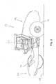
- a drive system 10 according to the invention will be explained in detail, will be described below with reference to the Fig. 2 explains the basic structure of a construction machine 12, in which the drive system 10 of Fig. 1 can be integrated.
- This construction machine 10 comprises at a rear carriage 14 drive wheels 16 which can be driven by the drive system 10 for advancing the constructed as a soil compactor construction machine 12 on the underground to be compacted 18.
- a driver's cab 20 is further provided, in which a person controlling the construction machine 12 finds space and from which the various functionalities of the construction machine 12 can be controlled.
- a compressor roller 24 is provided on a front-mounted vehicle 22 hingedly connected to the rear carriage 14 to steer the construction machine 12 designed as a soil compactor. With this compressor roller 24, the substrate 18 on which the construction machine 12 moves, compacted.
- the compressor roller 24 may be associated with an imbalance mass arrangement, which may be received for example in the interior of the compressor roller 24 and for generating a vibratory movement, ie a periodic up-down movement of the compactor roller 24, or / And for generating an oscillatory movement, ie a reciprocating movement of the compressor roller 24 in the circumferential direction, can be put into operation. Also, this can, as explained below, the in Fig. 1 shown drive system 10 are used.
- FIG. 2 the construction machine 12 shown in the form of a soil compactor is shown only in terms of its essential aspects and only as an example of a machine in which the drive system 10 of the Fig. 1 Application can be found.
- this could instead of the drive wheels 16 with another, then, for example, for propulsion of the soil compactor by the drive system 10 of Fig. 1 be designed for rotation to be driven compressor roller.
- the construction machine 12 could also be designed in the form of a wheel loader, a bulldozer, an excavator or the like.
- the drive system 10 of Fig. 1 comprises as a main energy source, for example, designed as a diesel internal combustion engine drive unit 26.
- This drive unit 26 is drivingly coupled or coupled for example via a clutch assembly, a hydrodynamic torque converter or the like with a gear assembly 28.
- About the gear assembly 28 can be provided by the drive unit 26 Drive torque to be transferred or distributed to different system areas.
- One of these system areas comprises a hydraulic drive circuit 30 with a hydraulic drive pump 32 integrated therein.
- This can be permanently coupled to the gear arrangement 28 or be coupled to the gear arrangement 28, for example via a clutch arrangement.
- this fluid z.
- hydraulic oil in the hydraulic drive circuit 30 um, creating a in Fig. 1 not shown hydraulic traction motor or possibly several hydraulic traction motors are driven, so that a torque can be transmitted to the drive wheels 16 of the construction machine 12, for example.
- a self-constructed and working hydraulic drive circuit can be provided.
- a hydraulic working circuit namely a hydraulic working circuit is called.
- This also includes a hydraulic pump, so here is a hydraulic working pump 36.
- These hydraulic working pump 36 may be permanently coupled to the gear assembly 28 or coupled for example via a coupling arrangement to the gear assembly 28. During operation of the hydraulic working pump 36, this generates a fluid circulation, z.
- one or more hydraulic working motors may be provided, through which, for example, the unbalance mass arrangement in the compressor roller 24 can be driven.
- hydraulic pumps 32, 36 advantageously with variable displacement, such as swashplate pumps, may be designed to adjust in this way the fluid circulation in the form of high pressure circuits hydraulic circuits 30, 34 and thus the therein also transferable torque can.
- the drive system 10 further includes a hydraulic drive assist unit, generally designated 38.
- the hydraulic pump / motor assembly 40 is switchable between an operating state in which it is operable as a pump, and an operating state in which it is operable as a motor.
- this assembly is constructed as a swash plate assembly.
- Fig. 1 One recognizes in Fig. 1 in that the hydraulic drive assisting unit 38 and the drive unit 26 are coupled to each other in parallel via the gear arrangement 28 with the various hydraulic circuits 30, 34 or can be coupled.
- a direct torque exchange described below in more detail, for example, between the power plant 26 and the hydraulic circuits 30, 34 and also a direct torque exchange between the hydraulic drive assisting unit 38 and the hydraulic circuits 30, 34 is possible.
- the hydraulic drive assisting unit 38 further includes a pressurized fluid reservoir 42 which may be charged by the operation of the hydraulic pump / motor assembly 40 as a pump.
- the hydraulic pump / motor assembly 40 fluid, z.
- hydraulic oil from a preferably pressureless fluid reservoir 44 in the direction of the pressure fluid reservoir 42 promote.
- a charge / discharge valve unit 48 is provided in a line 46 leading from the hydraulic pump / motor assembly 40 to the pressure fluid reservoir 42.
- This z. B. by electrical excitation to be adjusted charge / discharge valve unit 48 is, for example, by a biasing spring or the like in the in Fig. 1 biased illustrated in which it interrupts the flow connection between the hydraulic pump / motor assembly 40 and the pressure fluid reservoir 42.
- the charge / discharge valve unit 48 may be formed so that it is effective in this state as a check valve, which although a fluid flow from the hydraulic pump / motor assembly 40 to the pressure fluid reservoir 42 allows, but prevents fluid flow in the reverse direction.
- electrical energization of the charge / discharge valve unit 48 it is brought into its release state, in which the flow connection between the pressure fluid accumulator 42 and the hydraulic pump / motor assembly 40 is released.
- Valve unit 54 is an example of an electrically excitable expansion valve unit 54, which is biased by spring bias, for example, in a ground state in which it releases the flow connection between the pressure fluid reservoir 42 and the fluid reservoir 44.
- the expansion valve unit 54 Upon activation of the expansion valve unit 54, for example by electrical excitation, it is switched to its state interrupting the flow connection between the pressure fluid reservoir 42 and the fluid reservoir 44.
- the expansion valve unit 54 may be designed so that it is effective in this state as a check valve, which in principle permits fluid flow from the fluid reservoir 44 in the direction of the pressure fluid accumulator 42, but prevents fluid flow in the reverse direction.
- a manual expansion valve unit 56 Parallel to the expansion valve unit 54 is a manual expansion valve unit 56 provided. This can be brought by manual operation in their the flow connection between the pressure fluid reservoir 42 and the fluid reservoir 44 releasing state.
- an overload valve unit 58 is provided in the line 52, which, when the fluid pressure in the pressure fluid accumulator 42 and the portion 50 of the line 48 exceeds a predetermined limit pressure, a relaxation of the pressure fluid reservoir 42 to the fluid reservoir 44 permits , For example, it can be provided that at maximum loading in the pressure fluid reservoir 42, a fluid pressure of about 300 bar prevail. With such a design, the overload valve unit 58 may be dimensioned so that it establishes a flow connection between the pressure fluid reservoir 42 and the fluid reservoir 44 at a pressure of 300 bar excess pressure in the pressure fluid reservoir 42 until the fluid pressure in the pressure fluid reservoir 42 has fallen below this limit again ,
- the hydraulic drive assisting unit 38 further includes a circulation valve unit 60.
- This is provided in the flow path between the hydraulic pump / motor assembly 40 and the fluid reservoir 44, and branches from between the hydraulic pump / motor assembly 40 and the charge / discharge unit.
- the circulation valve unit 60 is basically biased to a state where there is fluid communication between the hydraulic pump / motor assembly 40 and the fluid reservoir 44. By z. B. electrical excitation, this circulation valve unit 60 can be brought into a state in which this flow connection is interrupted. In this condition, the recirculation valve unit 60 may function as a check valve which inhibits flow from the hydraulic pump / motor assembly 40 to the fluid reservoir 44, but releases flow in the other direction.
- the circulation valve unit 60 can be positioned in the locked position
- Charge / Discharge valve assembly 48 may then be utilized to establish flow communication between hydraulic pump / motor assembly 40 and fluid reservoir 44 when fluid circulation is to take place from fluid reservoir 44 and back into fluid reservoir 44 without furthering pressurized fluid reservoir 42 to load. This may be advantageous to maintain a minimum fluid flow through the hydraulic pump / motor assembly 40 to dissipate heat generated in the area of this assembly.
- an overload valve unit 64 is further arranged, which can be dimensioned so that it releases a flow connection to the fluid reservoir 44 at a limit pressure above the maximum boost pressure, for example at a limit pressure of about 330 bar excessive pressure build-up, in particular in the region of the conduit 46 to prevent.
- a check valve 66 is provided in parallel with the circulation valve unit 60 and the overload valve unit 64. This is switched so that it allows a flow from the fluid reservoir 44 in the conduit 46, in particular the portion 62 thereof, but prevents flow in the other direction, so as to create a negative pressure in the region of the conduit 46th to prevent.
- valve units to be adjusted either by electrical excitation or by manual actuation and a flow path to the fluid reservoir 44 ie the expansion valve unit 54, the manual expansion valve unit 56 and the circulation valve unit 60 are flow restrictor arrangements 68, 70, 72 is provided, which cause throttling of the fluid flow to the fluid reservoir 44, in particular when very large pressure differences exist between the pressure fluid reservoir 42 and the fluid reservoir 44.
- the drive assisting unit 38 further includes a cranking valve unit 74 disposed in a bypass flow path 76 bypassing the charge / discharge valve unit 48.
- This bypass flow path opens into the sections 62 and 50, respectively, of the conduit 46.
- a flow restrictor arrangement 78 is provided in the flow direction from the pressure fluid accumulator 42 to the hydraulic pump / motor assembly 40 upstream, that is before the starting valve unit 74.
- the start-up valve unit 74 may be biased into a ground state shutting off the bypass flow path 76 and may be configured to act as a check valve in this ground state and allow flow from the hydraulic pump / motor assembly 40 to the pressure fluid accumulator 42. but prevents a flow in the other direction.
- the starting valve unit 74 may be brought into a fluid communication state from the pressure fluid reservoir 42 to the hydraulic pump / motor assembly 40.
- the starting valve unit 74 is preferably designed such that it can provide variable, preferably adjustable volume flows, in order in this way to be able to vary the volume flow directed in the direction of the hydraulic pump / motor assembly 40 accordingly.
- the starting valve unit 74 may be formed as a proportional valve.
- the flow restrictor arrangement 78 provided in the bypass flow path 76 in front of the starting valve unit 74 ensures that only a reduced volume flow can flow from the pressure fluid accumulator 42 to the starting valve unit 74, so that a volume flow already reduced relative to the volume flow that can basically be dispensed from the pressure fluid accumulator 42
- Start-up valve unit 74 may be regulated to utilize a volumetric flow directed to the hydraulic pump / motor assembly 44 in a cranking condition in engine operation of the hydraulic pump / motor assembly 40 via the gear assembly 28 as starting torque for the prime mover 26 provide effective drive assist torque.
- FIG. 1 shows a state in which the hydraulic drive support unit 38 is connected so that the pressure fluid reservoir 42 is in communication with the fluid reservoir 44, so a possibly built-up pressure can relax or no pressure is built up. This is a condition that can be taken when the drive system 10 is out of service.
- the drive system 10 is operated, for example, the in Fig. 2 advancing illustrated soil compactor and thereby compressing the substrate 18 also taking advantage of vibration and / or oscillatory movements of the compressor roller 24, the charge / discharge valve unit 48 is energized so that they in their connection between the pressure fluid reservoir 42 and the hydraulic pump / Motor assembly 40 is producing state.
- the expansion valve unit 54 and the circulation valve unit 60 are also energized to bring them into their locked state.
- the drive unit 26 can drive in this state via the gear assembly 28, the two hydraulic pumps 32, 36 for the traction drive and the drive of the unbalance mass arrangement.
- the hydraulic pump / motor assembly 40 is driven so that it works as a pump fluid from the fluid reservoir 44 into the pressure fluid reservoir 42 promotes.
- This condition can be maintained for as long as until the pressure fluid accumulator 42 has reached a threshold load, which may for example be 85% of the maximum load. At a maximum boost pressure of about 300 bar, this threshold load can thus correspond to a boost pressure of about 255 bar.
- the hydraulic pump / motor assembly 44 can continue to operate in pump mode, albeit at a reduced delivery rate, in order to compensate for and compensate for any leakage losses from the pressure fluid accumulator 42 via the valve units shut off in particular in the direction of the fluid reservoir 44 ensure that pressure is maintained that is close to the threshold load.
- the hydraulic pump / motor assembly 40 is placed in a state with increased flow rate, so that the required or desired pressure build-up in the pressure fluid reservoir 42 is achieved. This process can be continued or repeated until the maximum loading of the pressure fluid reservoir 42, ie the maximum charge pressure of, for example, 300 bar, is reached. If so, the hydraulic pump / motor assembly 40 can be re-adjusted to a lower flow rate state to cause the pressure fluid accumulator 42 to utilize at least one energy recovery event to the maximum boost pressure increased pressure is maintained.
- this energy recovery operation can be used to further load the pressure fluid reservoir 42, even if the recovery of energy is possible only from one of the two hydraulic circuits 30, 34. Furthermore, in this state, the drive unit 26 can still be used to initiate an additional torque in the gear assembly 28, especially if can be transferred to an energy recovery operation, at the same time the pressure fluid reservoir 42 but not yet the state of the threshold load of, for example, about 85% of the maximum Loading has reached.
- the energy stored in the pressure fluid reservoir 42 can be utilized. to initiate drive assist torque into the transmission assembly 28 when operating the hydraulic pump / motor assembly 40 as the motor and directing it via the gear assembly 28 to one or both hydraulic circuits 30, 40, so as to assist in driving the respective hydraulic pump 32, 36, respectively use.
- the drive unit 26 can be operated such that it can deliver the drive torque which can be provided by this maximum, so that a total drive torque via the gear arrangement 28 too the hydraulic circuits 30, 34, which is composed of the drive torque of the drive unit 26, for example, the maximum drive torque thereof, and the drive assist torque of the hydraulic drive assist unit 38.
- the load / unload valve unit 48 is switched to its enable state so that the pressure fluid accumulator 42 may drain to the fluid reservoir 44 via the hydraulic pump / motor assembly 40.
- the torque that can be supplied by the hydraulic drive assisting unit 38 in this drive assisting operating state can be varied by appropriately adjusting the hydraulic pump / motor assembly 40 during engine operation.
- a start-stop operation may be provided for the drive unit 26, in which the drive unit 26 is temporarily switched off.
- This may for example be the case when a driving lever of the construction machine 12 is moved beyond the neutral position into a parking position, which on the one hand leads to the decrease in the rotational speed of the drive unit 12 to the idling speed and on the other hand can lead to preventing unintentional rolling away a Park brake assembly is activated.
- a predetermined period of time after the transition to this state, ie after activating the parking position the drive unit 26 can be turned off automatically, since it can be assumed that in this state does not directly a torque request will arise.
- the pressure fluid accumulator 42 is basically shut off, which means that all the pressure fluid reservoir 42 with either the fluid reservoir 44 or the hydraulic pump / motor assembly 44 connecting lines 46, 52 are shut off by the respectively therein valve units or valves.
- the pressurized fluid accumulator 42 is charged in this state, so that the pressurized fluid contained therein can be used to generate a drive assist torque.
- the hydraulic drive assisting unit 38 When an operation request is generated from this state, for example, by moving the driving lever of the construction machine 12 from the parking position to the neutral position from which, for example, the forward running position or the reverse running position can be taken, the hydraulic drive assisting unit 38 is operated in the starting operation state.
- the valve units 48, 54, 56, 60 remain in their blocking state and the starting valve unit 74 is switched into its release state, so that a volume flow of the pressure fluid contained in the pressure fluid reservoir 42 flows in the direction of the hydraulic pump / motor assembly 40.
- This is operated in this state as a motor in such a way that with the approaching via the starting valve unit 74 volume flow such a drive assist torque is generated that the drive unit 12 can be started.
- the starting valve unit 74 can be brought back into its blocking state and the hydraulic pump / motor assembly 40 can, for example, be operated again in the pump mode to recharge the pressure fluid reservoir 42, if necessary, or can Operate propulsion state, for example, when there is a high torque request when starting the construction machine 12 or when starting the hydraulic working circuit 34 to be operated as a motor and to provide a drive assist torque.
- the design of the drive system 10 makes it possible to design the drive unit 26 with respect to the maximum torque provided by this drive torque, that this maximum drive torque is smaller than a maximum occurring during operation of the construction machine 12 request torque.
- this maximum drive torque is smaller than a maximum occurring during operation of the construction machine 12 request torque.
- the hydraulic drive assisting unit 38 can provide the drive assisting torque, it is possible to introduce a total drive torque into the hydraulic circuits 30, 34 corresponding to the requested torque, thus operating the construction machine 12 appropriately to be able to.
- Fig. 1 shown drive system can be varied in various ways, in particular with regard to the configuration of the hydraulic drive assist unit.
- several, for example, parallel-connected pressure fluid reservoir could be provided.
- the various valves or valve units may each be provided as separately constructed and interconnected by lines assemblies or may be integrated into a valve block, which contributes to a compact, but nevertheless working with high reliability Ausgetaltung.
- the various hydraulic pumps as well as the hydraulic pump / motor assembly with the gear assembly permanently so not be coupled via the torque flow interrupting clutch assemblies or the like.
- the torque requirement or fluid delivery rate or performance can be varied. If a respective hydraulic circuit or the hydraulic drive assistance unit is not to be operated, the hydraulic pumps or the hydraulic pump / motor assembly can be switched to a neutral state.
- the above-described aspect of operating the drive assisting unit 38 in the starting operation state can be particularly advantageously combined with the likewise described aspect of operating the hydraulic drive assisting unit 38 in the circulation operation state in which the hydraulic pump / motor assembly 40 Fluid is directed from the fluid reservoir 44 via the recirculation valve unit 60 and back to the fluid reservoir 44 to generate a cooling action for the hydraulic pump / motor assembly 40, and may equally advantageously be combined alternatively or additionally with the foregoing described aspect of the design of the drive unit 26 such that the maximum drive torque that can be provided by this is smaller than the maximum demand torques occurring during operation, in such a state the drive assist torque which can be provided by the hydraulic drive assisting unit 38 can be used in conjunction with the provided by the drive unit 26 drive torque to provide a total torque that is sufficient even in the highest torque request state to operate the drive system 10 in the requested manner.
Landscapes
- Engineering & Computer Science (AREA)
- General Engineering & Computer Science (AREA)
- Mechanical Engineering (AREA)
- Mining & Mineral Resources (AREA)
- Civil Engineering (AREA)
- Structural Engineering (AREA)
- Chemical & Material Sciences (AREA)
- Combustion & Propulsion (AREA)
- Physics & Mathematics (AREA)
- Fluid Mechanics (AREA)
- Transportation (AREA)
- Analytical Chemistry (AREA)
- Fluid-Pressure Circuits (AREA)
- Road Paving Machines (AREA)
Abstract
Description
- Die vorliegende Erfindung betrifft ein Antriebssystem, insbesondere für eine selbstfahrende Baumaschine, insbesondere Bodenverdichter, umfassend:
- ein eine Brennkraftmaschine umfassendes Antriebsaggregat,
- wenigstens einen Hydraulikkreislauf mit einer durch das Antriebsaggregat antreibbaren Hydraulikpumpe,
- eine Hydraulik-Antriebsunterstützungseinheit mit einer Hydraulik-Pumpe/Motor-Baugruppe und wenigstens einem Druckfluidspeicher, wobei die Hydraulik-Pumpe/Motor-Baugruppe mit dem Antriebsaggregat oder/und wenigstens einem Hydraulikkreislauf antriebsmäßig gekoppelt oder koppelbar ist, wobei die Hydraulik-Pumpe/Motor-Baugruppe in einem Ladebetriebszustand durch das Antriebsaggregat oder/und wenigstens einen Hydraulikkreislauf als Pumpe zum Beladen wenigstens eines Druckfluidspeichers betreibbar ist und in einem Antriebsunterstützungsbetriebszustand als Motor zur Bereitstellung eines Antriebsunterstützungsdrehmomentes für die Hydraulikpumpe wenigstens eines Hydraulikkreislaufs betreibbar ist.
- Ein derartiges Antriebssystem ist aus der
WO 2013/074164A1 als Antriebssystem einer als Radlader ausgebildeten Baumaschine bekannt. Bei diesem bekannten Antriebssystem ist ein Antriebsaggregat über eine Getriebeanordnung mit verschiedenen Hydraulikkreisläufen antriebsmäßig gekoppelt. Diese Hydraulikkreisläufe umfassen einen Hydraulik-Fahrkreislauf mit einer durch das Antriebsaggregat antreibbaren Hydraulik-Fahrpumpe und einem im Betrieb der Hydraulik-Fahrpumpe durch das strömende Fluid angetriebenen Hydraulik-Fahrmotor zum Antrieb der Antriebsräder des Radladers. Ferner sind ein bzw. mehrere Hydraulik-Arbeitskreisläufe vorgesehen. Auch diese umfassen jeweils eine durch das Antriebsaggregat über die Getriebeanordnung antreibbare Hydraulik-Arbeitspumpe. Durch den durch diese Pumpen generierten Hydraulikdruck können beispielsweise Kolben/Zylinder-Einheiten aktiviert werden, um im Arbeitsbetrieb des Radladers eine Schaufel zu bewegen. Dieses Antriebssystem umfasst ferner eine Hydraulik-Antriebsunterstützungseinheit. Diese umfasst eine durch das Antriebsaggregat über die Getriebeanordnung antreibbare Hydraulik-Pumpe/Motor-Baugruppe, welche im Pumpenbetrieb einen Druckfluidspeicher lädt, also den Druck des darin gespeicherten Fluids erhöht. Die Hydraulik-Pumpe/Motor-Baugruppe dieser Hydraulik-Antriebsunterstützungseinheit kann auch als Hydraulikmotor betrieben werden, um unter Entspannung des Drucks in dem Druckfluidspeicher ein Drehmoment zu generieren, welches über die Getriebeanordnung auf die verschiedenen Hydraulikkreisläufe, also den Hydraulik-Fahrkreislauf und den bzw. die Hydraulik-Arbeitskreisläufe übertragen werden kann. Die Hydraulik-Antriebsunterstützungseinheit kann somit ein Antriebsunterstützungsdrehmoment liefern. - Es ist die Aufgabe der vorliegenden Erfindung, ein Antriebssystem, insbesondere für eine selbstfahrende Baumaschine, insbesondere Bodenverdichter, vorzusehen, welches eine effizientere Ausnutzung der Hydraulik-Antriebsunterstützungseinheit ermöglicht.
- Erfindungsgemäß wird diese Aufgabe gelöst durch ein Antriebssystem, insbesondere für eine selbstfahrende Baumaschine, insbesondere Bodenverdichter, umfassend:
- ein eine Brennkraftmaschine umfassendes Antriebsaggregat,
- wenigstens einen Hydraulikkreislauf mit einer durch das Antriebsaggregat antreibbaren Hydraulikpumpe,
- eine Hydraulik-Antriebsunterstützungseinheit mit einer Hydraulik-Pumpe/Motor-Baugruppe und wenigstens einem Druckfluidspeicher, wobei die Hydraulik-Pumpe/Motor-Baugruppe mit dem Antriebsaggregat oder/und wenigstens einem Hydraulikkreislauf antriebsmäßig gekoppelt oder koppelbar ist, wobei die Hydraulik-Pumpe/Motor-Baugruppe in einem Ladebetriebszustand durch das Antriebsaggregat oder/und wenigstens einen Hydraulikkreislauf als Pumpe zum Beladen wenigstens eines Druckfluidspeichers betreibbar ist und in einem Antriebsunterstützungsbetriebszustand als Motor zur Bereitstellung eines Antriebsunterstützungsdrehmomentes für die Hydraulikpumpe wenigstens eines Hydraulikkreislaufs betreibbar ist.
- Dabei ist weiter vorgesehen, dass die Hydraulik-Pumpe/Motor-Baugruppe in einem Anlassbetriebszustand als Motor zum Anlassen des Antriebsaggregats betreibbar ist.
- Durch das Ausnutzen der Hydraulik-Pumpe/Motor-Baugruppe als Motor zum Anlassen des Antriebsaggregats besteht die Möglichkeit, die Hydraulik-Antriebsunterstützungseinheit in einem weiteren Betriebszustand, also dem Anlassbetriebszustand, zu nutzen. Dies entlastet andere Systembereiche, wie einen beispielsweise in Zuordnung zu dem Antriebsaggregat allgemein vorgesehenen, elektrisch zu betreibenden Anlasser und gestattet andererseits das vorübergehende energiesparende Abstellen des Antriebsaggregats, wenn dieses beispielsweise während eines vorübergehenden Parkens einer mit einem derartigen Antriebssystem ausgestatteten Baumaschine nicht zur Erzeugung eines Antriebsdrehmoments benötigt wird.
- Um die in einem Druckfluidspeicher gespeicherte Energie zum Anlassen des Antriebsaggregats in einfacher Weise nutzen zu können, wird vorgeschlagen, dass die Hydraulik-Antriebsunterstützungseinheit ein Anlass-Ventileinheit zum wahlweisen Freigeben/Unterbrechen einer Strömungsverbindung zwischen wenigstens einem Druckfluidspeicher und der HydraulikPumpe/Motor-Baugruppe wenigstens in Strömungsrichtung von dem Druckfluidspeicher zur Hydraulik-Pumpe/Motor-Baugruppe umfasst. Dieses Anlassventil kann also speziell für die zum Anlassen erforderlichen Volumenströme ausgebildet sein, kann insbesondere dazu ausgebildet sein, den Volumenstrom auch definiert einzustellen bzw. zu regeln, um zu gewährleisten, dass durch die Hydraulik-Pumpe/Motor-Baugruppe im Anlassbetriebszustand auch nur das für das Anlassen des Antriebsaggregats erforderliche Antriebsunterstützungsdrehmoment bereitgestellt wird.
- Um bei dem erfindungsgemäßen Antriebssystem für den Anlassbetriebszustand grundsätzlich eine Drosselung auf dafür erforderliche Volumenströme bereitstellen zu können, wird vorgeschlagen, dass im Strömungsweg zwischen dem wenigstens einen Druckspeicher und der Anlass-Ventileinheit oder/und im Strömungsweg zwischen der Anlass-Ventileinheit und der Hydraulik-Pumpe/Motor-Baugruppe eine Strömungsdrosselanordnung vorgesehen ist.
- Eine definierte Einstellung des zum Anlassen des Antriebsaggregats erforderlichen Drehmoments kann in einfacher Weise dadurch erhalten werden, dass die Anlass-Ventileinheit ein Proportionalventil umfasst.
- Die definierte Beladung bzw. Entladung eines Druckfluidspeichers zur Aufnahme bzw. zum Abgeben von Druckfluid kann dadurch erhalten werden, dass die Hydraulik-Antriebsunterstützungseinheit eine Lade/Entlade-Ventileinheit zum wahlweisen Freigeben/Unterbrechen einer Strömungsverbindung zwischen der Hydraulik-Pumpe/Motor-Baugruppe und wenigstens einem Druckfluidspeicher wenigstens in Strömungsrichtung vom Druckfluidspeicher zur Hydraulik-Pumpe/Motor-Baugruppe umfasst und eine Entspannungs-Ventileinheit zum wahlweisen Freigeben/Unterbrechen einer Strömungsverbindung zwischen wenigstens einem Druckfluidspeicher und einem Fluidreservoir wenigstens in Strömungsrichtung vom Druckfluidspeicher zum Fluidreservoir umfasst.
- Eine insbesondere in Fehlerzuständen auftretende, undefinierte Entleerung eines Druckfluidspeichers in Richtung zur Hydraulik-Pumpe/Motor-Baugruppe kann bei einer vorteilhaften Weiterbildung des erfindungsgemäßen Antriebssystems beispielsweise dadurch verhindert werden, dass die Anlass-Ventileinheit oder/und die Lade/Entlade-Ventileinheit in einen die Strömungsverbindung unterbrechenden Grundzustand vorgespannt ist oder/und dass die Entspannungs-Ventileinheit in einen die Strömungsverbindung freigebenden Grundzustand vorgespannt ist.
- Die Hydraulik-Antriebsunterstützungseinheit umfasst vorteilhafterweise einen offenen Kreislauf. Ferner besteht bei einer besonders vorteilhaften Weiterbildung zwischen wenigstens einem Fluidkreislauf, vorzugsweise jedem Fluidkreislauf und der Hydraulik-Antriebsunterstützungseinheit keine Fluidaustauschverbindung. Dies ermöglicht es, einen derartigen Fluidkreislauf als geschlossenen Hochdruckkreislauf auszugestalten.
- Die vorliegende Erfindung betrifft ferner eine selbstfahrende Baumaschine, insbesondere Bodenverdichter, welche ein erfindungsgemäß aufgebautes Antriebssystem umfasst.
- Ferner betrifft die vorliegende Erfindung ein Verfahren zum Betreiben eines Antriebssystems, insbesondere für eine selbstfahrende Baumaschine, insbesondere Bodenverdichter, das Antriebssystem umfassend ein eine Brennkraftmaschine umfassendes Antriebsaggregat, wenigstens einen Hydraulikkreislauf mit einer durch das Antriebsaggregat antreibbaren Hydraulikpumpe, eine Hydraulik-Antriebsunterstützungseinheit mit einer HydraulikPumpe/Motor-Baugruppe und wenigstens einem Druckfluidspeicher, wobei die Hydraulik-Pumpe/Motor-Baugruppe mit dem Antriebsaggregat oder/und wenigstens einem Hydraulikkreislauf antriebsmäßig gekoppelt oder koppelbar ist, wobei die Hydraulik-Pumpe/Motor-Baugruppe in einem Ladebetriebszustand durch das Antriebsaggregat oder/und wenigstens einen Hydraulikkreislauf als Pumpe zum Beladen wenigstens eines Druckfluidspeichers betreibbar ist und in einem Antriebsunterstützungsbetriebszustand als Motor zur Bereitstellung eines Antriebsunterstützungsdrehmomentes für die Hydraulikpumpe wenigstens eines Hydraulikkreislaufs betreibbar ist, bei welchem Verfahren die Hydraulik-Pumpe/Motor-Baugruppe in einem Anlassbetriebszustand als Motor zum Anlassen des Antriebsaggregats betrieben wird.
- Das Antriebsaggregat kann beispielsweise dann außer Betrieb gesetzt werden, wenn die Drehzahl des Antriebsaggregats unter eine Schwellendrehzahl abfällt oder unter dieser ist, vorzugsweise im Bereich einer Leerlaufdrehzahl des Antriebsaggregats ist. Dieser Zustand kann beispielsweise dann eingenommen werden, wenn ein in einer derartigen Baumaschine vorgesehener Fahrhebel über eine Neutralstellung hinaus in eine Parkstellung bewegt wird, wodurch signalisiert wird, dass zumindest vorübergehend ein Fahr- bzw. Arbeitsbetrieb nicht gefordert wird.
- Wird bei dem erfindungsgemäßen Verfahren eine Betriebsanforderung für das Antriebssystem erzeugt, beispielsweise durch Verstellen eines Fahrhebels von der Parkstellung in die Neutralstellung, kann das Antriebssystem die Hydraulik-Pumpe/Motor-Baugruppe im Anlassbetriebszustand betreiben, so dass das Antriebsaggregat angelassen wird und wieder zur Erzeugung eines Antriebsdrehmoments zur Verfügung steht.
- Die Erfindung wird nachfolgend mit Bezug auf die beiliegenden Figuren detailliert beschrieben. Es zeigt:
- Fig. 1
- in prinzipartiger Darstellung den Aufbau eines Antriebssystems für eine selbstfahrende Baumaschine;
- Fig. 2
- eine als selbstfahrender Bodenverdichter ausgebildete Baumaschine, in welcher das Antriebssystem der
Fig. 1 zur Anwendung kommen kann. - Bevor im Folgenden mit Bezug auf die
Fig. 1 ein erfindungsgemäßes Antriebssystem 10 detailliert erläutert wird, wird im Folgenden mit Bezug auf dieFig. 2 der grundsätzliche Aufbau einer Baumaschine 12 erläutert, in welche das Antriebssystem 10 derFig. 1 integriert werden kann. Diese Baumaschine 10 umfasst an einem Hinterwagen 14 Antriebsräder 16, die durch das Antriebssystem 10 zur Voranbewegung der als Bodenverdichter ausgebildeten Baumaschine 12 auf dem zu verdichtenden Untergrund 18 angetrieben werden können. Am Hinterwagen 14 ist ferner eine Führerkabine 20 vorgesehen, in welcher eine die Baumaschine 12 steuernde Person Platz findet und von welcher aus die verschiedenen Funktionalitäten der Baumaschine 12 gesteuert werden können. - An einem zum Lenken der als Bodenverdichter ausgebildeten Baumaschine 12 mit dem Hinterwagen 14 gelenkig verbundenen Vorderwagen 22 ist eine Verdichterwalze 24 vorgesehen. Mit dieser Verdichterwalze 24 wird der Untergrund 18, auf welchem die Baumaschine 12 sich bewegt, verdichtet. Um diesen Verdichtungsvorgang in definierter Art und Weise durchführen zu können, kann der Verdichterwalze 24 eine Unwuchtmassenanordnung zugeordnet sein, die beispielsweise im Inneren der Verdichterwalze 24 aufgenommen sein kann und zur Erzeugung einer Vibrationsbewegung, also einer periodischen Auf-Ab-Bewegung der Verdichterwalze 24, oder/und zur Erzeugung einer Oszillationsbewegung, also einer Hin-Her-Bewegung der Verdichterwalze 24 in Umfangsrichtung, in Betrieb gesetzt werden kann. Auch hierzu kann, wie im Folgenden noch dargelegt, das in
Fig. 1 dargestellte Antriebssystem 10 eingesetzt werden. - Es sei darauf hingewiesen, dass in
Fig. 2 die in Form eines Bodenverdichters dargestellte Baumaschine 12 nur hinsichtlich ihrer wesentlichen Aspekte und nur als ein Beispiel einer Maschine dargestellt ist, in welcher das Antriebssystem 10 derFig. 1 Anwendung finden kann. Beispielsweise könnte bei Ausgestaltung als Bodenverdichter dieser anstelle der Antriebsräder 16 mit einer weiteren, dann beispielsweise auch zum Vortrieb des Bodenverdichters durch das Antriebssystem 10 derFig. 1 zur Drehung anzutreibenden Verdichterwalze ausgestaltet sein. Auch könnte die Baumaschine 12 in Form eines Radladers, einer Planierraupe, eines Baggers oder dergleichen ausgebildet sein. - Das Antriebssystem 10 der
Fig. 1 umfasst als Hauptenergiequelle ein beispielsweise als Diesel-Brennkraftmaschine ausgebildetes Antriebsaggregat 26. Dieses Antriebsaggregat 26 ist beispielsweise über eine Kupplungsanordnung, einen hydrodynamischen Drehmomentwandler oder dergleichen mit einer Getriebeanordnung 28 antriebsmäßig gekoppelt oder koppelbar. Über die Getriebeanordnung 28 kann das vom Antriebsaggregat 26 bereitgestellte Antriebsdrehmoment auf verschiedene Systembereiche übertragen bzw. verteilt werden. - Einer dieser Systembereiche umfasst einen Hydraulik-Fahrkreislauf 30 mit einer in diesen integrierten Hydraulik-Fahrpumpe 32. Diese kann mit der Getriebeanordnung 28 permanent gekoppelt sein oder beispielsweise über eine Kupplungsanordnung an die Getriebeanordnung 28 angekoppelt sein bzw. werden. Bei Antreiben der Hydraulik-Fahrpumpe 32 wälzt diese Fluid, z. B. Hydrauliköl, in dem Hydraulik-Fahrkreislauf 30 um, wodurch ein in
Fig. 1 nicht dargestellter Hydraulik-Fahrmotor oder ggf. mehrere Hydraulik-Fahrmotoren angetrieben werden, so dass ein Drehmoment beispielsweise auf die Antriebsräder 16 der Baumaschine 12 übertragen werden kann. Es ist hier darauf hinzuweisen, dass beispielsweise in Zuordnung zu jedem Antriebsrad 16 oder beispielsweise in Zuordnung zu jedem Kettenfahrwerk einer Baumaschine ein eigenständig aufgebauter und arbeitender Hydraulik-Fahrkreislauf vorgesehen sein kann. - Mit 34 ist ein weiterer Hydraulikkreislauf, nämlich ein Hydraulik-Arbeitskreislauf, bezeichnet. Auch dieser umfasst eine Hydraulikpumpe, hier also eine Hydraulik-Arbeitspumpe 36. Auch diese Hydraulik-Arbeitspumpe 36 kann mit der Getriebeanordnung 28 permanent gekoppelt sein oder beispielsweise über eine Kupplungsanordnung an die Getriebeanordnung 28 angekoppelt werden. Im Betrieb der Hydraulik-Arbeitspumpe 36 erzeugt diese eine Fluidumwälzung, z. B. von Hydrauliköl, im Hydraulik-Arbeitskreislauf 34. Auch im Hydraulik-Arbeitskreislauf 34 können ein bzw. mehrere Hydraulik-Arbeitsmotoren vorgesehen sein, durch welche beispielsweise die Unwuchtmassenanordnung in der Verdichterwalze 24 angetrieben werden kann.
- Es ist darauf hinzuweisen, dass die Hydraulikpumpen 32, 36 vorteilhafterweise mit variablem Fördervolumen, beispielsweise als Taumelscheibenpumpen, ausgebildet sein können, um auf diese Art und Weise die Fluidumwälzung in den als Hochdruckkreisläufen ausgebildeten Hydraulikkreisläufen 30, 34 und somit das darin auch übertragbare Drehmoment einstellen zu können.
- Das Antriebssystem 10 umfasst ferner eine allgemein mit 38 bezeichnete Hydraulik-Antriebsunterstützungseinheit. Diese umfasst eine Hydraulik-Pumpe/Motor-Baugruppe 40, die mit der Getriebeanordnung 28 permanent gekoppelt sein kann oder beispielsweise über eine Kupplungsanordnung an die Getriebeanordnung 28 angekoppelt oder ankoppelbar ist und auf diese Art und Weise mit der Getriebeanordnung 28 und über diese mit dem Antriebsaggregat 26 bzw. den Hydraulikkreisläufen 30, 34, insbesondere deren Hydraulikpumpen 32, 36 antriebsmäßig gekoppelt ist. Die HydraulikPumpe/Motor-Baugruppe 40 ist zwischen einem Betriebszustand, in welchem diese als Pumpe betreibbar ist, und einem Betriebszustand, in welchem diese als Motor betreibbar ist, umschaltbar. Vorteilhafterweise ist auch diese Baugruppe als Taumelscheibenaggregat aufgebaut.
- Man erkennt in
Fig. 1 , dass die Hydraulik-Antriebsunterstützungseinheit 38 und das Antriebsaggregat 26 zueinander parallel über die Getriebeanordnung 28 mit den verschiedenen Hydraulikkreisläufen 30, 34 gekoppelt oder koppelbar sind. Somit ist ein nachfolgend detaillierter beschriebener direkter Drehmomentenaustausch beispielsweise zwischen dem Antriebsaggregat 26 und den Hydraulikkreisläufen 30, 34 und auch ein direkter Drehmomentenaustausch zwischen der Hydraulik-Antriebsunterstützungseinheit 38 und den Hydraulikkreisläufen 30, 34 möglich. - Die Hydraulik-Antriebsunterstützungseinheit 38 umfasst ferner einen Druckfluidspeicher 42, welcher durch den Betrieb der Hydraulik-Pumpe/Motor-Baugruppe 40 als Pumpe geladen werden kann. Dazu kann die HydraulikPumpe/Motor-Baugruppe 40 Fluid, z. B. Hydrauliköl, aus einem vorzugsweise drucklosen Fluidreservoir 44 in Richtung zum Druckfluidspeicher 42 fördern.
- In einer von der Hydraulik-Pumpe/Motor-Baugruppe 40 zum Druckfluidspeicher 42 führenden Leitung 46 ist eine Lade/Entlade-Ventileinheit 48 vorgesehen. Diese z. B. durch elektrische Erregung zu verstellende Lade/Entlade-Ventileinheit 48 ist beispielsweise durch eine Vorspannfeder oder dergleichen in den in
Fig. 1 dargestellten Grundzustand vorgespannt, in welchem sie die Strömungsverbindung zwischen der Hydraulik-Pumpe/Motor-Baugruppe 40 und dem Druckfluidspeicher 42 unterbricht. Dabei kann die Lade/Entlade-Ventileinheit 48 so ausgebildet sein, dass sie in diesem Zustand als Rückschlagventil wirksam ist, welches zwar einen Fluidstrom von der Hydraulik-Pumpe/Motor-Baugruppe 40 zum Druckfluidspeicher 42 zulässt, jedoch einen Fluidstrom in umgekehrter Richtung unterbindet. Beispielsweise durch elektrische Erregung der Lade/Entlade-Ventileinheit 48 wird diese in ihren Freigabezustand gebracht, in welchem die Strömungsverbindung zwischen dem Druckfluidspeicher 42 und der Hydraulik-Pumpe/Motor-Baugruppe 40 freigegeben ist. - Von dem zwischen dem Druckfluidspeicher 42 und der Lade/Entlade-Ventileinheit 48 liegenden Abschnitt 50 der Leitung 46 zweigt eine zum Fluidreservoir 44 führende Leitung 52 ab. Diese Leitung 52 stellt grundsätzlich eine Verbindung zwischen dem Druckfluidspeicher 42 und dem Fluidreservoir 44 her. In der Leitung 52 sind parallel zueinander drei Ventileinheiten 54, 56, 58 angeordnet. Die Ventileinheit 54 ist eine beispielsweise elektrisch erregbare Entspannungs-Ventileinheit 54, die beispielsweise durch Federvorspannung in einen Grundzustand vorgespannt ist, in welchem sie die Strömungsverbindung zwischen dem Druckfluidspeicher 42 und dem Fluidreservoir 44 freigibt. Bei Aktivierung der Entspannungs-Ventileinheit 54 beispielsweise durch elektrische Erregung wird diese in ihren die Strömungsverbindung zwischen dem Druckfluidspeicher 42 und dem Fluidreservoir 44 unterbrechenden Zustand geschaltet. Dabei kann die Entspannungs-Ventileinheit 54 so ausgebildet sein, dass sie in diesem Zustand als Rückschlagventil wirksam ist, welches eine Fluidströmung vom Fluidreservoir 44 in Richtung zum Druckfluidspeicher 42 grundsätzlich zulässt, eine Fluidströmung in umgekehrter Richtung jedoch unterbindet.
- Parallel zur Entspannungs-Ventileinheit 54 ist eine Manuell-Entspannungs-Ventileinheit 56 vorgesehen. Diese kann durch manuelle Betätigung in ihren die Strömungsverbindung zwischen dem Druckfluidspeicher 42 und dem Fluidreservoir 44 freigebenden Zustand gebracht werden.
- Parallel zu den Ventileinheiten 54, 56 ist in der Leitung 52 eine Überlast-Ventileinheit 58 vorgesehen, welche dann, wenn der Fluiddruck im Druckfluidspeicher 42 bzw. im Abschnitt 50 der Leitung 48 einen vorbestimmten Grenzdruck übersteigt, eine Entspannung des Druckfluidspeichers 42 zum Fluidreservoir 44 zulässt. Beispielsweise kann vorgesehen sein, dass bei maximaler Beladung im Druckfluidspeicher 42 ein Fluiddruck von etwa 300 bar vorherrschen soll. Bei derartiger Auslegung kann die Überlast-Ventileinheit 58 so dimensioniert sein, dass sie bei einen Druck von 300 bar übersteigendem Druck im Druckfluidspeicher 42 eine Strömungsverbindung zwischen dem Druckfluidspeicher 42 und dem Fluidreservoir 44 herstellt, bis der Fluiddruck im Druckfluidspeicher 42 wieder unter diesen Grenzwert abgefallen ist.
- Die Hydraulik-Antriebsunterstützungseinheit 38 umfasst ferner eine Umwälz-Ventileinheit 60. Diese ist im Strömungsweg zwischen der HydraulikPumpe/Motor-Baugruppe 40 und dem Fluidreservoir 44 vorgesehen und zweigt von einem zwischen der Hydraulik-Pumpe/Motor-Baugruppe 40 und der Lade/Entlade-Ventileinheit 48 liegenden Abschnitt 62 der Leitung 46 ab. Die Umwälz-Ventileinheit 60 ist grundsätzlich in einen Zustand vorgespannt, in welchem eine Strömungsverbindung zwischen der Hydraulik-Pumpe/Motor-Baugruppe 40 und dem Fluidreservoir 44 besteht. Durch z. B. elektrische Erregung kann diese Umwälz-Ventileinheit 60 in einen Zustand gebracht werden, in welchem diese Strömungsverbindung unterbrochen ist. In diesem Zustand kann die Umwälz-Ventileinheit 60 als Rückschlagventil wirksam sein, das eine Strömung von der Hydraulik-Pumpe/Motor-Baugruppe 40 zum Fluidreservoir 44 unterbindet, eine Strömung in der anderen Richtung jedoch freigibt.
- Die Umwälz-Ventileinheit 60 kann bei in der Sperrstellung positionierter Lade/Entlade-Ventileinheit 48 dann zum Herstellen einer Strömungsverbindung zwischen der Hydraulik-Pumpe/Motor-Baugruppe 40 und dem Fluidreservoir 44 genutzt werden, wenn eine Fluidumwälzung aus dem Fluidreservoir 44 und zurück in das Fluidreservoir 44 stattfinden soll, ohne dabei den Druckfluidspeicher 42 weiter zu laden. Dies kann vorteilhaft sein, um einen minimalen Fluidstrom durch die Hydraulik-Pumpe/Motor-Baugruppe 40 aufrecht zu erhalten, um im Bereich dieser Baugruppe generierte Wärme abzuführen.
- Parallel zu der Umwälz-Ventileinheit 60 ist ferner eine Überlast-Ventileinheit 64 angeordnet, welche so dimensioniert sein kann, dass sie bei über dem maximalen Ladedruck liegendem Grenzdruck, beispielsweise bei einem Grenzdruck von etwa 330 bar, eine Strömungsverbindung zum Fluidreservoir 44 freigibt, um einen übermäßigen Druckaufbau insbesondere im Bereich der Leitung 46 zu verhindern.
- Ferner ist parallel zur Umwälz-Ventileinheit 60 und zur Überlast-Ventileinheit 64 ein Rückschlagventil 66 vorgesehen. Dieses ist so geschaltet, dass es eine Strömung von dem Fluidreservoir 44 in die Leitung 46, insbesondere den Abschnitt 62 derselben, zulässt, eine Strömung in der anderen Richtung jedoch unterbindet, um auf diese Art und Weise das Entstehen eines Unterdrucks im Bereich der Leitung 46 zu verhindern.
- In Zuordnung zu allen entweder durch elektrische Erregung oder durch manuelle Betätigung zu verstellenden und einen Strömungsweg zum Fluidreservoir 44 freigebenden Ventileinheiten, also der Entspannungs-Ventileinheit 54, der Manuell-Entspannungs-Ventileinheit 56 und der Umwälz-Ventileinheit 60, sind Strömungsdrosselanordnungen 68, 70, 72 vorgesehen, welche insbesondere beim Bestehen sehr großer Druckdifferenzen zwischen dem Druckfluidspeicher 42 und dem Fluidreservoir 44 eine Drosselung des Fluidstroms zum Fluidreservoir 44 bewirken.
- Die Antriebs-Unterstützungseinheit 38 umfasst ferner eine Anlass-Ventileinheit 74, die in einem die Lade/Entlade-Ventileinheit 48 umgehenden Bypassströmungsweg 76 angeordnet ist. Dieser Bypassströmungsweg mündet in die Abschnitte 62 bzw. 50 der Leitung 46 ein. In Strömungsrichtung von dem Druckfluidspeicher 42 zur Hydraulik-Pumpe/Motor-Baugruppe 40 stromaufwärts, also vor der Anlass-Ventileinheit 74, ist eine Strömungsdrosselanordnung 78 vorgesehen.
- Die Anlass-Ventileinheit 74 kann beispielsweise in einen den Bypassströmungsweg 76 absperrenden Grundzustand vorgespannt sein und kann so ausgebildet sein, dass sie in diesem Grundzustand als Rückschlagventil wirksam ist und sie eine Strömung von der Hydraulik-Pumpe/Motor-Baugruppe 40 zum Druckfluidspeicher 42 zulässt, eine Strömung in der anderen Richtung jedoch unterbindet. Durch beispielsweise elektrische Erregung kann die Anlass-Ventileinheit 74 in einen eine Strömungsverbindung vom Druckfluidspeicher 42 zur Hydraulik-Pumpe/Motor-Baugruppe 40 freigebenden Zustand gebracht werden. Dabei ist vorzugsweise die Anlass-Ventileinheit 74 so ausgebildet, dass sie veränderbare, vorzugsweise regelbare Volumenströme bereitstellen kann, um auf diese Art und Weise den in Richtung zur Hydraulik-Pumpe/Motor-Baugruppe 40 geleiteten Volumenstrom entsprechend variieren zu können. Beispielsweise kann die Anlass-Ventileinheit 74 als Proportionalventil ausgebildet sein. Zusätzlich sorgt die im Bypassströmungsweg 76 vor der Anlass-Ventileinheit 74 vorgesehene Strömungsdrosselanordnung 78 dafür, dass nur ein reduzierter Volumenstrom vom Druckfluidspeicher 42 zur Anlass-Ventileinheit 74 strömen kann, so dass ein bezüglich des aus dem Druckfluidspeicher 42 grundsätzlich abgebbaren Volumenstroms bereits reduzierter Volumenstrom durch die Anlass-Ventileinheit 74 reguliert werden kann, um einen in einem Anlassbetriebszustand zur Hydraulik-Pumpe/Motor-Baugruppe 44 geleiteten Volumenstrom dazu zu nutzen, in einem Motorbetrieb der Hydraulik-Pumpe/Motor-Baugruppe 40 über die Getriebeanordnung 28 ein als Anlassdrehmoment für das Antriebsaggregat 26 wirksames Antriebsunterstützungsdrehmoment bereitzustellen.
- Bei dem vorangehend beschriebenen Antriebssystem 10 besteht zwischen der Hydraulik-Antriebsunterstützungseinheit 38 und den für den Betrieb der Baumaschine 10 erforderlichen Hydraulikkreisläufen 30, 34 keine Fluidaustauschverbindung. Die Hydraulik-Antriebsunterstützungseinheit 38 ist mit den Hydraulikkreisläufen 30, 34 ausschließlich antriebsmäßig, also mechanisch gekoppelt, nämlich über die Getriebeanordnung 28. Dies gestattet es, die Hydraulik-Antriebsunterstützungseinheit 38 als offenen Kreislauf, also als Niederdruckkreislauf auszugestalten, während die Hydraulikkreisläufe 30, 34 als geschlossene Hydraulikkreisläufe, also als Hochdruckkreisläufe, ausgebildet sein können.
- Das in
Fig. 1 dargestellte Antriebssystem 10 kann in verschiedenen Betriebsmodi arbeiten. DieFig. 1 zeigt einen Zustand, bei welchem die Hydraulik-Antriebsunterstützungseinheit 38 so geschaltet ist, dass der Druckfluidspeicher 42 in Verbindung mit dem Fluidreservoir 44 ist, also ein darin ggf. aufgebauter Druck sich entspannen kann bzw. kein Druck aufgebaut wird. Dies ist ein Zustand, der dann eingenommen werden kann, wenn das Antriebssystem 10 außer Betrieb ist. - Soll das Antriebssystem 10 betrieben werden, beispielsweise um den in
Fig. 2 dargestellten Bodenverdichter voranzubewegen und dabei auch unter Ausnutzung von Vibrations- oder/und Oszillationsbewegungen der Verdichterwalze 24 den Untergrund 18 zu verdichten, wird die Lade/Entlade-Ventileinheit 48 erregt, so dass sie in ihren eine Verbindung zwischen dem Druckfluidreservoir 42 und der Hydraulik-Pumpe/Motor-Baugruppe 40 herstellenden Zustand ist. Gleichzeitig werden auch die Entspannungs-Ventileinheit 54 und die Umwälz-Ventileinheit 60 angesteuert bzw. erregt, um sie in ihren Sperrzustand zu bringen. Das Antriebsaggregat 26 kann in diesem Zustand über die Getriebeanordnung 28 die beiden Hydraulikpumpen 32, 36 für den Fahrantrieb und den Antrieb der Unwuchtmassenanordnung antreiben. Ferner wird die Hydraulik-Pumpe/Motor-Baugruppe 40 angetrieben, so dass diese als Pumpe arbeitend Fluid aus dem Fluidreservoir 44 in den Druckfluidspeicher 42 fördert. Dieser Zustand kann so lange beibehalten werden, bis der Druckfluidspeicher 42 eine Schwellenbeladung erreicht hat, die beispielsweise bei 85 % der maximalen Beladung liegen kann. Bei einem maximalen Ladedruck von etwa 300 bar kann diese Schwellenbeladung also einem Ladedruck von etwa 255 bar entsprechen. - Ist dieser Zustand erreicht, kann die Hydraulik-Pumpe/Motor-Baugruppe 44 weiterhin im Pumpenbetrieb, wenngleich mit geminderter Förderleistung weiterbetrieben werden, um etwaige Leckageverluste aus dem Druckfluidspeicher 42 über die diesen insbesondere in Richtung zum Fluidreservoir 44 hin absperrenden Ventileinheiten zu kompensieren und dafür zu sorgen, dass ein Druck aufrecht erhalten bleibt, der in etwa der Schwellenbeladung entspricht.
- Wird im Betrieb der Baumaschine 12 Energie frei, beispielsweise weil diese verzögert werden soll oder der Betrieb der Unwuchtmassenanordnung eingestellt werden soll, so findet in den Hydraulikkreisläufen 30, 34 eine Umkehr der Drehmomentenübertragungsrichtung statt, so dass vorübergehend die Hydraulikpumpen 32, 36, angetrieben durch einen durch die jeweiligen nicht dargestellten Hydraulikmotoren generierten Fluidstrom, als Motoren wirksam sind und ein Drehmoment in die Getriebeanordnung 28 einleiten. Dieses Drehmoment kann über die Getriebeanordnung 28 in die HydraulikPumpe/Motor-Baugruppe 40 eingeleitet werden, welche dann wieder als Pumpe genutzt werden kann, um den Druck im Druckfluidspeicher 42 weiter zu erhöhen, beispielsweise bis der maximale Ladedruck erreicht ist. Dazu wird die Hydraulik-Pumpe/Motor-Baugruppe 40 in einen Zustand mit erhöhter Förderleistung gestellt, so dass der erforderliche bzw. gewünschte Druckaufbau im Druckfluidspeicher 42 erreicht wird. Dieser Vorgang kann so lange fortgesetzt bzw. so oft wiederholt werden, bis die maximale Beladung des Druckfluidspeichers 42, also der maximale Ladedruck von beispielsweise 300 bar, erreicht ist. Ist dies der Fall, kann die Hydraulik-Pumpe/Motor-Baugruppe 40 wieder in einen Zustand mit geringerer Förderleistung bzw. Förderrate verstellt werden, um dafür zu sorgen, dass im Druckfluidspeicher 42 der unter Ausnutzung wenigstens eines Energierückgewinnungsvorgangs auf den maximalen Ladedruck erhöhte Druck aufrecht erhalten bleibt.
- Es ist darauf hinzuweisen, dass dieser Energierückgewinnungsbetrieb zum weiteren Beladen des Druckfluidspeichers 42 auch dann genutzt werden kann, wenn nur aus einem der beiden Hydraulikkreisläufe 30, 34 die Rückgewinnung von Energie möglich ist. Ferner kann auch in diesem Zustand das Antriebsaggregat 26 noch genutzt werden, um ein zusätzliches Drehmoment in die Getriebeanordnung 28 einzuleiten, insbesondere wenn in einen Energierückgewinnungsbetrieb übergegangen werden kann, gleichzeitig der Druckfluidspeicher 42 jedoch noch nicht den Zustand der Schwellenbeladung von beispielsweise etwa 85 % der maximalen Beladung erreicht hat.
- Insbesondere im Energierückgewinnungsbetrieb ist es besonders vorteilhaft, dass über die Getriebeanordnung 28 eine direkte Verbindung zwischen den Hydraulikkreisläufen 30, 34 und der Hydraulik-Antriebsunterstützungseinheit 38 besteht, so dass die im Energierückgewinnungsbetrieb freigesetzte Energie ohne beispielsweise über das Antriebsaggregat 26 geleitet zu werden in Richtung zur Hydraulik-Antriebsunterstützungseinheit 38 geleitet werden kann.
- Besteht im Bereich von einem oder beiden Hydraulikkreisläufen 30, 34 eine hohe Drehmomentenanforderung, beispielsweise weil kurzzeitig die Baumaschine 12 eine vergleichsweise hohe Steigung überwinden soll oder über eine Randsteinkante oder ein sonstiges Hindernis hinweg bewegt werden soll, kann die im Druckfluidspeicher 42 gespeicherte Energie genutzt werden, um bei Betreiben der Hydraulik-Pumpe/Motor-Baugruppe 40 als Motor ein Antriebsunterstützungsdrehmoment in die Getriebeanordnung 28 einzuleiten und dieses über die Getriebeanordnung 28 zu einem oder beiden Hydraulikkreisläufen 30, 40 zu leiten, also zum unterstützenden Antreiben der jeweiligen Hydraulikpumpe 32 bzw. 36 zu nutzen. In diesem Zustand kann beispielsweise auch das Antriebsaggregat 26 so betrieben werden, dass es das durch dieses maximal bereitstellbare Antriebsdrehmoment liefern kann, so dass ein Gesamtantriebsdrehmoment über die Getriebeanordnung 28 zu den Hydraulikkreisläufen 30, 34 geleitet wird, welches sich aus dem Antriebsdrehmoment des Antriebsaggregats 26, beispielsweise dem maximalen Antriebsdrehmoment desselben, und dem Antriebsunterstützungsdrehmoment der Hydraulik-Antriebsunterstützungseinheit 38 zusammensetzt. Um diesen Zustand zu erreichen, ist die Lade/Entlade-Ventileinheit 48 in ihren Freigabezustand geschaltet, so dass der Druckfluidspeicher 42 sich über die Hydraulik-Pumpe/Motor-Baugruppe 40 in Richtung zum Fluidreservoir 44 entleeren kann. Das in diesem Antriebsunterstützungsbetriebszustand durch die Hydraulik-Antriebsunterstützungseinheit 38 bereitstellbare Drehmoment kann durch entsprechende Verstellung der Hydraulik-Pumpe/Motor-Baugruppe 40 im Motorbetrieb variiert werden.
- Soll die mit dem Antriebssystem 10 ausgestattete Baumaschine 12 vorübergehend nicht genutzt werden, jedoch nicht vollständig deaktiviert werden, so kann für das Antriebsaggregat 26 ein Start-Stopp-Betrieb vorgesehen sein, in welchem das Antriebsaggregat 26 vorübergehend abgestellt wird. Dies kann beispielsweise dann der Fall sein, wenn ein Fahrhebel der Baumaschine 12 über die Neutralposition hinaus in eine Parkposition bewegt wird, was einerseits zum Abfall der Drehzahl des Antriebsaggregats 12 auf die Leerlaufdrehzahl führt und andererseits dazu führen kann, dass zum Verhindern eines unbeabsichtigten Wegrollens eine Parkbremsanordnung aktiviert wird. Beispielsweise eine vorbestimmte Zeitdauer nach dem Übergang in diesen Zustand, also nach dem Aktivieren der Parkposition, kann das Antriebsaggregat 26 automatisch abgestellt werden, da davon auszugehen ist, dass in diesem Zustand nicht unmittelbar eine Drehmomentenanforderung entstehen wird. In diesem Zustand ist der Druckfluidspeicher 42 grundsätzlich abgesperrt, was bedeutet, dass alle den Druckfluidspeicher 42 entweder mit dem Fluidreservoir 44 oder der Hydraulik-Pumpe/Motor-Baugruppe 44 verbindenden Leitungen 46, 52 durch die darin jeweils vorgesehenen Ventileinheiten bzw. Ventile abgesperrt sind. Der Druckfluidspeicher 42 ist in diesem Zustand geladen, so dass das darin enthaltene Druckfluid zur Erzeugung eines Antriebsunterstützungsdrehmoments genutzt werden kann.
- Wird ausgehend von diesem Zustand eine Betriebsanforderung generiert, beispielsweise durch Verstellen des Fahrhebels der Baumaschine 12 aus der Parkposition in die Neutralposition, aus welcher dann beispielsweise die Vorwärtsfahrposition oder die Rückwärtsfahrposition eingenommen werden kann, wird die Hydraulik-Antriebsunterstützungseinheit 38 im Anlassbetriebszustand betrieben. Dazu bleiben die Ventileinheiten 48, 54, 56, 60 in ihrem Sperrzustand und die Anlass-Ventileinheit 74 wird in ihren Freigabezustand geschaltet, so dass ein Volumenstrom des im Druckfluidspeicher 42 enthaltenen Druckfluids in Richtung zur Hydraulik-Pumpe/Motor-Baugruppe 40 strömt. Diese wird in diesem Zustand als Motor betrieben und zwar derart, dass mit dem über die Anlass-Ventileinheit 74 heranströmenden Volumenstrom ein derartiges Antriebsunterstützungsdrehmoment generiert wird, dass das Antriebsaggregat 12 angelassen werden kann. Ist das Antriebsaggregat 26 wieder im Betrieb, kann die Anlass-Ventileinheit 74 wieder in ihren Sperrzustand gebracht werden und die Hydraulik-Pumpe/Motor-Baugruppe 40 kann beispielsweise wieder im Pumpenbetrieb betrieben werden, um erforderlichenfalls den Druckfluidspeicher 42 wieder zu laden, oder kann im Antriebsunterstützungszustand betrieben werden, um beispielsweise dann, wenn beim Anfahren der Baumaschine 12 oder bei der Inbetriebnahme des Hydraulik-Arbeitskreislaufs 34 eine hohe Drehmomentenanforderung besteht, als Motor betrieben zu werden und ein Antriebsunterstützungsdrehmoment bereitzustellen.
- Die Ausgestaltung des Antriebssystems 10 ermöglicht es, das Antriebsaggregat 26 so hinsichtlich des durch dieses maximal bereitstellbaren Antriebsdrehmoments auszulegen, dass dieses maximale Antriebsdrehmoment kleiner ist, als ein im Betrieb der Baumaschine 12 maximal auftretendes Anforderungsdrehmoment. Da in Zuständen, in welchen eine derartige Drehmomentenanforderung vorliegt, die Hydraulik-Antriebsunterstützungseinheit 38 das Antriebsunterstützungsdrehmoment bereitstellen kann, ist es möglich, ein Gesamtantriebsdrehmoment in die Hydraulikkreisläufe 30, 34 einzuleiten, welches dem angeforderten Drehmoment entspricht, um somit die Baumaschine 12 in geeigneter Weise betreiben zu können.
- Durch diese Auslegung des Antriebsaggregats 26 mit vergleichsweise niedrigem maximalem Antriebsdrehmoment wird bei allgemein geringer Baugröße eine effiziente Energieausnutzung gewährleistet, bei welcher insbesondere auch die in verschiedenen Zuständen der Baumaschine 12 frei werdende Energie genutzt werden kann, um den Druckfluidspeicher 42 zu laden.
- Es sei darauf hingewiesen, dass das in
Fig. 1 dargestellte Antriebssystem insbesondere hinsichtlich der Ausgestaltung der Hydraulik-Antriebsunterstützungseinheit in verschiedenster Weise variiert werden kann. So könnten selbstverständlich mehrere beispielsweise parallel geschaltete Druckfluidspeicher vorgesehen sein. Auch können die verschiedenen Ventile bzw. Ventileinheiten jeweils als separat aufgebaute und durch Leitungen miteinander verbundene Baugruppen vorgesehen sein oder können in einen Ventilblock integriert sein, was zu einer kompakten, gleichwohl jedoch mit hoher Betriebssicherheit arbeitenden Ausgetaltung beiträgt. - Ferner können beispielsweise die verschiedenen Hydraulikpumpen ebenso wie die Hydraulik-Pumpe/Motor-Baugruppe mit der Getriebeanordnung permanent, also nicht über den Drehmomentenfluss unterbrechende Kupplungsanordnungen oder dergleichen gekoppelt sein. Durch die Verstellung dieser beispielsweise als Taumelscheibenaggregate ausgebildeten Pumpen bzw. Baugruppen kann dann die Drehmomentenanforderung bzw. Fluidförderrate bzw. -leistung variiert werden. Soll ein jeweiliger Hydraulikkreislauf bzw. die Hydraulik-Antriebsunterstützungseinheit nicht betrieben werden, so können die Hydraulikpumpen bzw. die Hydraulik-Pumpe/Motor-Baugruppe in einen Neutralzustand geschaltet werden.
- Der vorangehend beschriebene Aspekt des Betreibens der Antriebs-Unterstützungseinheit 38 im Anlassbetriebszustand kann in besonders vorteilhafter Weise kombiniert werden mit dem ebenfalls beschriebenen Aspekt des Betreibens der Hydraulik-Antriebsunterstützungseinheit 38 im Umwälzbetriebszustand, in welchem durch die Hydraulik-Pumpe/Motor-Baugruppe 40 Fluid aus dem Fluidspeicher 44 über die Umwälz-Ventileinheit 60 und zurück zum Fluidspeicher 44 geleitet wird, um eine Kühlwirkung für die Hydraulik-Pumpe/Motor-Baugruppe 40 zu generieren, und kann gleichermaßen alternativ oder zusätzlich in vorteilhafter Weise auch kombiniert werden mit dem vorangehend beschriebenen Aspekt der Auslegung des Antriebsaggregats 26 derart, dass das durch dieses bereitstellbare maximale Antriebsdrehmoment kleiner ist, als die im Betrieb auftretenden maximalen Anforderungsdrehmomente, wobei in einem derartigen Zustand das durch die Hydraulik-Antriebsunterstützungseinheit 38 bereitstellbare Antriebsunterstützungsdrehmoment genutzt werden kann, um in Verbindung mit dem durch das Antriebsaggregat 26 bereitgestellten Antriebsdrehmoment ein Gesamtdrehmoment bereitzustellen, das auch im Zustand höchster Drehmomentenanforderung genügt, um das Antriebssystem 10 in der angeforderten Art und Weise betreiben zu können.
Claims (12)
- Antriebssystem, insbesondere für eine selbstfahrende Baumaschine, insbesondere Bodenverdichter, umfassend:- ein eine Brennkraftmaschine umfassendes Antriebsaggregat (26),- wenigstens einen Hydraulikkreislauf (30, 34) mit einer durch das Antriebsaggregat (26) antreibbaren Hydraulikpumpe (32, 36),- eine Hydraulik-Antriebsunterstützungseinheit (38) mit einer Hydraulik-Pumpe/Motor-Baugruppe (40) und wenigstens einem Druckfluidspeicher (42), wobei die Hydraulik-Pumpe/Motor-Baugruppe (40) mit dem Antriebsaggregat (26) oder/und wenigstens einem Hydraulikkreislauf (30, 34) antriebsmäßig gekoppelt oder koppelbar ist, wobei die Hydraulik-Pumpe/Motor-Baugruppe (40) in einem Ladebetriebszustand durch das Antriebsaggregat (26) oder/und wenigstens einen Hydraulikkreislauf (30, 34) als Pumpe zum Beladen wenigstens eines Druckfluidspeichers (42) betreibbar ist und in einem Antriebsunterstützungsbetriebszustand als Motor zur Bereitstellung eines Antriebsunterstützungsdrehmomentes für die Hydraulikpumpe (32, 36) wenigstens eines Hydraulikkreislaufs (30, 34) betreibbar ist,dadurch gekennzeichnet, dass die Hydraulik-Pumpe/Motor-Baugruppe (40) in einem Anlassbetriebszustand als Motor zum Anlassen des Antriebsaggregats (26) betreibbar ist.
- Antriebssystem nach Anspruch 1,
dadurch gekennzeichnet, dass die Hydraulik-Antriebsunterstützungseinheit (38) ein Anlass-Ventileinheit (74) zum wahlweisen Freigeben/Unterbrechen einer Strömungsverbindung zwischen wenigstens einem Druckfluidspeicher (42) und der Hydraulik-Pumpe/Motor-Baugruppe (40) wenigstens in Strömungsrichtung von dem Druckfluidspeicher (42) zur Hydraulik-Pumpe/Motor-Baugruppe (40) umfasst. - Antriebssystem nach Anspruch 2,
dadurch gekennzeichnet, dass im Strömungsweg zwischen dem wenigstens einen Druckspeicher (42) und der Anlass-Ventileinheit (74) oder/und im Strömungsweg zwischen der Anlass-Ventileinheit (74) und der Hydraulik-Pumpe/Motor-Baugruppe (40) eine Strömungsdrosselanordnung (78) vorgesehen ist. - Antriebssystem nach Anspruch 2 oder 3,
dadurch gekennzeichnet, dass die Anlass-Ventileinheit (74) ein Proportionalventil umfasst. - Antriebssystem nach einem der Ansprüche 1 bis 4,
dadurch gekennzeichnet, dass die Hydraulik-Antriebsunterstützungseinheit (38) eine Lade/Entlade-Ventileinheit (48) zum wahlweisen Freigeben/Unterbrechen einer Strömungsverbindung zwischen der Hydraulik-Pumpe/Motor-Baugruppe (40) und wenigstens einem Druckfluidspeicher (42) wenigstens in Strömungsrichtung vom Druckfluidspeicher (42) zur Hydraulik-Pumpe/Motor-Baugruppe (40) umfasst und eine Entspannungs-Ventileinheit (54) zum wahlweisen Freigeben/Unterbrechen einer Strömungsverbindung zwischen wenigstens einem Druckfluidspeicher (42) und einem Fluidreservoir (44) wenigstens in Strömungsrichtung vom Druckfluidspeicher (42) zum Fluidreservoir (44) umfasst. - Antriebssystem nach einem der Ansprüche 3 bis 5,
dadurch gekennzeichnet, dass die Anlass-Ventileinheit (74) oder/und die Lade/Entlade-Ventileinheit (48) in einen die Strömungsverbindung unterbrechenden Grundzustand vorgespannt ist oder/und dass die Entspannungs-Ventileinheit (54) in einen die Strömungsverbindung freigebenden Grundzustand vorgespannt ist. - Antriebssystem nach einem der Ansprüche 1 bis 6,
dadurch gekennzeichnet, dass die Hydraulik-Antriebsunterstützungseinheit (38) einen offenen Kreislauf umfasst. - Antriebssystem nach einem der Ansprüche 1 bis 7,
dadurch gekennzeichnet, dass zwischen wenigstens einem Fluidkreislauf (30, 34), vorzugsweise jedem Fluidkreislauf (30, 34), und der Hydraulik-Antriebsunterstützungseinheit (38) keine Fluidaustauschverbindung besteht. - Selbstfahrende Baumaschine, insbesondere Bodenverdichter, umfassend ein Antriebssystem (10) nach einem der vorhergehenden Ansprüche.
- Verfahren zum Betreiben eines Antriebssystems, insbesondere für eine selbstfahrende Baumaschine, insbesondere Bodenverdichter, das Antriebssystem umfassend:- ein eine Brennkraftmaschine umfassendes Antriebsaggregat (26),- wenigstens einen Hydraulikkreislauf (30, 34) mit einer durch das Antriebsaggregat (26) antreibbaren Hydraulikpumpe (32, 36),- eine Hydraulik-Antriebsunterstützungseinheit (38) mit einer Hydraulik-Pumpe/Motor-Baugruppe (40) und wenigstens einem Druckfluidspeicher (42), wobei die Hydraulik-Pumpe/Motor-Baugruppe (40) mit dem Antriebsaggregat (26) oder/und wenigstens einem Hydraulikkreislauf (30, 34) antriebsmäßig gekoppelt oder koppelbar ist, wobei die Hydraulik-Pumpe/Motor-Baugruppe (40) in einem Ladebetriebszustand durch das Antriebsaggregat (26) oder/und wenigstens einen Hydraulikkreislauf (30, 34) als Pumpe zum Beladen wenigstens eines Druckfluidspeichers (42) betreibbar ist und in einem Antriebsunterstützungsbetriebszustand als Motor zur Bereitstellung eines Antriebsunterstützungsdrehmomentes für die Hydraulikpumpe (32, 36) wenigstens eines Hydraulikkreislaufs (30, 34) betreibbar ist,bei welchem Verfahren die Hydraulik-Pumpe/Motor-Baugruppe (40) in einem Anlassbetriebszustand als Motor zum Anlassen des Antriebsaggregats (26) betrieben wird.
- Verfahren nach Anspruch 10,
dadurch gekennzeichnet, dass das Antriebsaggregat (26) dann außer Betrieb gesetzt wird, wenn die Drehzahl des Antriebsaggregats (26) unter einer Schwellendrehzahl ist, vorzugsweise im Bereich einer Leerlaufdrehzahl des Antriebsaggregats (26) ist. - Verfahren nach Anspruch 10 oder 11,
dadurch gekennzeichnet, dass nach Erzeugung einer Betriebsanforderung für das Antriebssystem (10) die Hydraulik-Pumpe/Motor-Baugruppe (40) im Anlassbetriebszustand betrieben wird.
Priority Applications (1)
| Application Number | Priority Date | Filing Date | Title |
|---|---|---|---|
| EP21153924.2A EP3839241B1 (de) | 2013-12-20 | 2014-11-14 | Antriebssystem, insbesondere für eine selbstfahrende baumaschine, insbesondere bodenverdichter |
Applications Claiming Priority (1)
| Application Number | Priority Date | Filing Date | Title |
|---|---|---|---|
| DE102013227035.6A DE102013227035A1 (de) | 2013-12-20 | 2013-12-20 | Antriebssystem, insbesondere für eine selbstfahrende Baumaschine, insbesondere Bodenverdichter |
Related Child Applications (2)
| Application Number | Title | Priority Date | Filing Date |
|---|---|---|---|
| EP21153924.2A Division EP3839241B1 (de) | 2013-12-20 | 2014-11-14 | Antriebssystem, insbesondere für eine selbstfahrende baumaschine, insbesondere bodenverdichter |
| EP21153924.2A Division-Into EP3839241B1 (de) | 2013-12-20 | 2014-11-14 | Antriebssystem, insbesondere für eine selbstfahrende baumaschine, insbesondere bodenverdichter |
Publications (2)
| Publication Number | Publication Date |
|---|---|
| EP2891791A1 true EP2891791A1 (de) | 2015-07-08 |
| EP2891791B1 EP2891791B1 (de) | 2021-03-10 |
Family
ID=51900252
Family Applications (2)
| Application Number | Title | Priority Date | Filing Date |
|---|---|---|---|
| EP14193125.3A Active EP2891791B1 (de) | 2013-12-20 | 2014-11-14 | Antriebssystem, insbesondere für eine selbstfahrende Baumaschine, insbesondere Bodenverdichter |
| EP21153924.2A Active EP3839241B1 (de) | 2013-12-20 | 2014-11-14 | Antriebssystem, insbesondere für eine selbstfahrende baumaschine, insbesondere bodenverdichter |
Family Applications After (1)
| Application Number | Title | Priority Date | Filing Date |
|---|---|---|---|
| EP21153924.2A Active EP3839241B1 (de) | 2013-12-20 | 2014-11-14 | Antriebssystem, insbesondere für eine selbstfahrende baumaschine, insbesondere bodenverdichter |
Country Status (5)
| Country | Link |
|---|---|
| US (1) | US10059184B2 (de) |
| EP (2) | EP2891791B1 (de) |
| JP (1) | JP5972351B2 (de) |
| CN (2) | CN204532651U (de) |
| DE (1) | DE102013227035A1 (de) |
Cited By (3)
| Publication number | Priority date | Publication date | Assignee | Title |
|---|---|---|---|---|
| CN106678098A (zh) * | 2016-12-30 | 2017-05-17 | 徐州重型机械有限公司 | 起重机液压控制系统和起重机 |
| WO2018036731A1 (de) * | 2016-08-23 | 2018-03-01 | Voith Patent Gmbh | Hydrostatisches system und pumpstation für eine öl- oder gas-pipeline |
| US20240229376A9 (en) * | 2022-10-21 | 2024-07-11 | Volvo Construction Equipment Ab | Hydraulic paver system, a method, and a control unit for operating an electric paver in different operation modes, an electric paver for constructing a road surface, a computer program, and a computer readable medium |
Families Citing this family (3)
| Publication number | Priority date | Publication date | Assignee | Title |
|---|---|---|---|---|
| TWI725553B (zh) | 2019-09-24 | 2021-04-21 | 友達光電股份有限公司 | 顯示裝置及其製造方法 |
| JP7009600B1 (ja) * | 2020-12-07 | 2022-01-25 | 日立建機株式会社 | 作業機械 |
| US11639594B2 (en) * | 2021-01-14 | 2023-05-02 | Deere & Company | Transmission system with traction motor-driven hydraulic circuit and method of controlling same |
Citations (6)
| Publication number | Priority date | Publication date | Assignee | Title |
|---|---|---|---|---|
| US6460500B1 (en) * | 1999-09-13 | 2002-10-08 | Honda Giken Kogyo Kabushiki Kaisha | Start control system for internal combustion engine |
| WO2011133072A1 (en) * | 2010-04-19 | 2011-10-27 | Parker Hannifin Ab | Arrangement for operating a hydraulic device |
| DE102011111924A1 (de) * | 2011-08-31 | 2013-02-28 | Atlas Weyhausen Gmbh | Baumaschine, insbesondere Radlader, Walze oder dergleichen Baufahrzeug |
| WO2013074164A1 (en) | 2011-11-17 | 2013-05-23 | Caterpillar Inc. | System and method for energy recovery |
| WO2013159851A1 (de) * | 2012-04-26 | 2013-10-31 | Deutz Aktiengesellschaft | Hydraulikhybrid |
| DE102012207238A1 (de) * | 2012-05-02 | 2013-11-07 | Robert Bosch Gmbh | Startvorrichtung |
Family Cites Families (17)
| Publication number | Priority date | Publication date | Assignee | Title |
|---|---|---|---|---|
| JP3018521U (ja) * | 1995-02-10 | 1995-11-21 | 日立建機ダイナパツク株式会社 | 転圧機械用ブレーキ装置 |
| JP2001253649A (ja) | 2000-03-15 | 2001-09-18 | Oil Drive Kogyo Kk | 油圧エレベータの油圧回路 |
| JP2003314510A (ja) * | 2002-04-22 | 2003-11-06 | Komatsu Ltd | 油圧エネルギー回生システム |
| JP2004028212A (ja) | 2002-06-26 | 2004-01-29 | Komatsu Ltd | 圧油エネルギー同時回収装置 |
| JP2004300947A (ja) * | 2003-03-28 | 2004-10-28 | Shin Caterpillar Mitsubishi Ltd | 作業機械のエンジン制御装置 |
| US20060108860A1 (en) * | 2004-11-23 | 2006-05-25 | Delaware Capital Formation | Brake energy recovery system |
| DE102006046127A1 (de) * | 2006-09-28 | 2008-04-03 | Robert Bosch Gmbh | Energiespeichereinheit |
| CN100427771C (zh) * | 2006-12-14 | 2008-10-22 | 浙江大学 | 一种液压配重可变的节能液压升降系统 |
| CN100535454C (zh) | 2007-06-25 | 2009-09-02 | 哈尔滨工业大学 | 二次调节流量耦联液压蓄能器储能静液传动装置 |
| DE202010018254U1 (de) * | 2010-12-16 | 2015-02-12 | Hamm Ag | Selbstfahrende Verdichtungswalze |
| DE102011104919A1 (de) * | 2011-04-04 | 2012-10-04 | Linde Material Handling Gmbh & Co. Kg | Antriebsstrang eines Fahrzeugs, insbesondere einer mobilen Arbeitsmaschine |
| JP2013091953A (ja) * | 2011-10-25 | 2013-05-16 | Nobuyuki Sugimura | 建設機械のエンジン始動補助機構 |
| JP5872268B2 (ja) | 2011-12-01 | 2016-03-01 | 株式会社小松製作所 | 作業車両の回生制御装置および作業車両の回生制御方法 |
| FR2989741A1 (fr) * | 2012-04-23 | 2013-10-25 | Manitou Bf | Dispositif d'arret automatique et de redemarrage automatique d'un moteur a combustion interne. |
| FR2993613B1 (fr) | 2012-07-20 | 2014-08-15 | Poclain Hydraulics Ind | Circuit hydraulique de mise en cylindree progressive d'un appareil hydraulique |
| CN203214493U (zh) * | 2013-03-15 | 2013-09-25 | 宝钢工业炉工程技术有限公司 | 升降设备在稳定载荷下的势能回收液压控制系统 |
| DE102013227032A1 (de) * | 2013-12-20 | 2015-06-25 | Hamm Ag | Antriebssystem, insbesondere für eine selbstfahrende Baumaschine, insbesondere Bodenverdichter |
-
2013
- 2013-12-20 DE DE102013227035.6A patent/DE102013227035A1/de not_active Ceased
-
2014
- 2014-11-14 EP EP14193125.3A patent/EP2891791B1/de active Active
- 2014-11-14 EP EP21153924.2A patent/EP3839241B1/de active Active
- 2014-12-18 CN CN201420807510.5U patent/CN204532651U/zh not_active Withdrawn - After Issue
- 2014-12-18 CN CN201410790978.2A patent/CN104728185B/zh active Active
- 2014-12-18 JP JP2014255949A patent/JP5972351B2/ja active Active
- 2014-12-18 US US14/574,890 patent/US10059184B2/en active Active
Patent Citations (6)
| Publication number | Priority date | Publication date | Assignee | Title |
|---|---|---|---|---|
| US6460500B1 (en) * | 1999-09-13 | 2002-10-08 | Honda Giken Kogyo Kabushiki Kaisha | Start control system for internal combustion engine |
| WO2011133072A1 (en) * | 2010-04-19 | 2011-10-27 | Parker Hannifin Ab | Arrangement for operating a hydraulic device |
| DE102011111924A1 (de) * | 2011-08-31 | 2013-02-28 | Atlas Weyhausen Gmbh | Baumaschine, insbesondere Radlader, Walze oder dergleichen Baufahrzeug |
| WO2013074164A1 (en) | 2011-11-17 | 2013-05-23 | Caterpillar Inc. | System and method for energy recovery |
| WO2013159851A1 (de) * | 2012-04-26 | 2013-10-31 | Deutz Aktiengesellschaft | Hydraulikhybrid |
| DE102012207238A1 (de) * | 2012-05-02 | 2013-11-07 | Robert Bosch Gmbh | Startvorrichtung |
Cited By (6)
| Publication number | Priority date | Publication date | Assignee | Title |
|---|---|---|---|---|
| WO2018036731A1 (de) * | 2016-08-23 | 2018-03-01 | Voith Patent Gmbh | Hydrostatisches system und pumpstation für eine öl- oder gas-pipeline |
| WO2018036730A1 (de) * | 2016-08-23 | 2018-03-01 | Voith Patent Gmbh | Pumpstation für eine pipeline und verfahren zum starten eines verbrennungsmotors in einer pumpstation |
| US10935012B2 (en) | 2016-08-23 | 2021-03-02 | Voith Patent Gmbh | Pumping station for a pipeline and method for starting a combustion engine in a pumping station |
| US11111908B2 (en) | 2016-08-23 | 2021-09-07 | Voith Patent Gmbh | Hydrostatic system and pumping station for an oil or gas pipeline |
| CN106678098A (zh) * | 2016-12-30 | 2017-05-17 | 徐州重型机械有限公司 | 起重机液压控制系统和起重机 |
| US20240229376A9 (en) * | 2022-10-21 | 2024-07-11 | Volvo Construction Equipment Ab | Hydraulic paver system, a method, and a control unit for operating an electric paver in different operation modes, an electric paver for constructing a road surface, a computer program, and a computer readable medium |
Also Published As
| Publication number | Publication date |
|---|---|
| EP3839241A1 (de) | 2021-06-23 |
| US20150174997A1 (en) | 2015-06-25 |
| CN104728185B (zh) | 2017-09-01 |
| DE102013227035A1 (de) | 2015-06-25 |
| CN104728185A (zh) | 2015-06-24 |
| EP2891791B1 (de) | 2021-03-10 |
| JP2015121088A (ja) | 2015-07-02 |
| US10059184B2 (en) | 2018-08-28 |
| CN204532651U (zh) | 2015-08-05 |
| EP3839241B1 (de) | 2024-10-30 |
| JP5972351B2 (ja) | 2016-08-17 |
Similar Documents
| Publication | Publication Date | Title |
|---|---|---|
| EP2531305B1 (de) | Vibrationsantrieb | |
| EP1963687B1 (de) | Verfahren zum steuern eines hydrostatischen antriebs | |
| EP3839241B1 (de) | Antriebssystem, insbesondere für eine selbstfahrende baumaschine, insbesondere bodenverdichter | |
| EP2886382B1 (de) | Antriebssystem, insbesondere für eine selbstfahrende Baumaschine, insbesondere Bodenverdichter | |
| EP2735657B1 (de) | Antriebsstrang eines Fahrzeugs, inbesondere einer mobilen Arbeitsmaschine | |
| DE102011104919A1 (de) | Antriebsstrang eines Fahrzeugs, insbesondere einer mobilen Arbeitsmaschine | |
| EP2735656B1 (de) | Antriebsstrang eines fahrzeugs | |
| EP2840252B1 (de) | Hydrostatisches Triebwerk | |
| DE112011103974T5 (de) | Hydraulikventilatorkreislauf mit Energiewiedergewinnung | |
| DE102011107061A1 (de) | Antriebsstrang eines Fahrzeugs, insbesondere einer mobilen Arbeitsmaschine | |
| WO2012080411A2 (de) | Selbstfahrende verdichtungswalze und verfahren zum betreiben einer selbstfahrenden verdichtungswalze | |
| WO2007076942A1 (de) | Antrieb mit energierückgewinnungs- und retarderfunktion | |
| EP2886381B1 (de) | Antriebssystem, insbesondere für eine selbstfahrende Baumaschine, insbesondere Bodenverdichter | |
| EP2735726B1 (de) | Hydrostatisches Triebwerk zum Starten eines Verbrennungsmotors | |
| DE102011105006A1 (de) | Antriebsstrang eines Fahrzeugs | |
| EP3095999B1 (de) | Hydrostatisches antriebssystem | |
| DE102011104921A1 (de) | Antriebsstrang einer mobilen Arbeitsmaschine | |
| EP2735727B1 (de) | Hydrostatisches Triebwerk als hydraulischer Starter eines Verbrennungsmotors | |
| EP2962883B9 (de) | Hydrostatisches antriebssystem | |
| DE10134789C2 (de) | Fahrantrieb für ein Kettenfahrzeug | |
| DE20306851U1 (de) | Schnellstarteinrichtung | |
| DE102005061165A1 (de) | Antrieb für ein Nebenaggregat oder Hilfsaggregat eines Kraftfahrzeugs | |
| DE102014118139A1 (de) | Hydrostatisches Antriebssystem |
Legal Events
| Date | Code | Title | Description |
|---|---|---|---|
| PUAI | Public reference made under article 153(3) epc to a published international application that has entered the european phase |
Free format text: ORIGINAL CODE: 0009012 |
|
| 17P | Request for examination filed |
Effective date: 20141114 |
|
| AK | Designated contracting states |
Kind code of ref document: A1 Designated state(s): AL AT BE BG CH CY CZ DE DK EE ES FI FR GB GR HR HU IE IS IT LI LT LU LV MC MK MT NL NO PL PT RO RS SE SI SK SM TR |
|
| AX | Request for extension of the european patent |
Extension state: BA ME |
|
| TPAC | Observations filed by third parties |
Free format text: ORIGINAL CODE: EPIDOSNTIPA |
|
| STAA | Information on the status of an ep patent application or granted ep patent |
Free format text: STATUS: EXAMINATION IS IN PROGRESS |
|
| 17Q | First examination report despatched |
Effective date: 20171010 |
|
| RIC1 | Information provided on ipc code assigned before grant |
Ipc: B60K 6/12 20060101ALN20190723BHEP Ipc: F02N 7/00 20060101AFI20190723BHEP Ipc: F15B 1/02 20060101ALI20190723BHEP Ipc: E02F 9/22 20060101ALI20190723BHEP Ipc: F15B 21/14 20060101ALI20190723BHEP |
|
| GRAP | Despatch of communication of intention to grant a patent |
Free format text: ORIGINAL CODE: EPIDOSNIGR1 |
|
| STAA | Information on the status of an ep patent application or granted ep patent |
Free format text: STATUS: GRANT OF PATENT IS INTENDED |
|
| RIC1 | Information provided on ipc code assigned before grant |
Ipc: F15B 21/14 20060101ALI20190917BHEP Ipc: E02F 9/22 20060101ALI20190917BHEP Ipc: F02N 7/00 20060101AFI20190917BHEP Ipc: F15B 1/02 20060101ALI20190917BHEP Ipc: B60K 6/12 20060101ALN20190917BHEP |
|
| INTG | Intention to grant announced |
Effective date: 20190930 |
|
| GRAJ | Information related to disapproval of communication of intention to grant by the applicant or resumption of examination proceedings by the epo deleted |
Free format text: ORIGINAL CODE: EPIDOSDIGR1 |
|
| STAA | Information on the status of an ep patent application or granted ep patent |
Free format text: STATUS: EXAMINATION IS IN PROGRESS |
|
| INTC | Intention to grant announced (deleted) | ||
| GRAP | Despatch of communication of intention to grant a patent |
Free format text: ORIGINAL CODE: EPIDOSNIGR1 |
|
| STAA | Information on the status of an ep patent application or granted ep patent |
Free format text: STATUS: GRANT OF PATENT IS INTENDED |
|
| RIC1 | Information provided on ipc code assigned before grant |
Ipc: F15B 21/14 20060101ALI20200116BHEP Ipc: E02F 9/22 20060101ALI20200116BHEP Ipc: F15B 1/02 20060101ALI20200116BHEP Ipc: B60K 6/12 20060101ALN20200116BHEP Ipc: F02N 7/00 20060101AFI20200116BHEP |
|
| INTG | Intention to grant announced |
Effective date: 20200204 |
|
| RIC1 | Information provided on ipc code assigned before grant |
Ipc: E02F 9/22 20060101ALI20200127BHEP Ipc: B60K 6/12 20060101ALN20200127BHEP Ipc: F15B 21/14 20060101ALI20200127BHEP Ipc: F15B 1/02 20060101ALI20200127BHEP Ipc: F02N 7/00 20060101AFI20200127BHEP |
|
| GRAJ | Information related to disapproval of communication of intention to grant by the applicant or resumption of examination proceedings by the epo deleted |
Free format text: ORIGINAL CODE: EPIDOSDIGR1 |
|
| STAA | Information on the status of an ep patent application or granted ep patent |
Free format text: STATUS: EXAMINATION IS IN PROGRESS |
|
| INTC | Intention to grant announced (deleted) | ||
| RIC1 | Information provided on ipc code assigned before grant |
Ipc: F02N 7/00 20060101AFI20200709BHEP Ipc: F15B 21/14 20060101ALI20200709BHEP Ipc: E02F 9/22 20060101ALI20200709BHEP Ipc: B60K 6/12 20060101ALN20200709BHEP Ipc: F15B 1/02 20060101ALI20200709BHEP |
|
| GRAP | Despatch of communication of intention to grant a patent |
Free format text: ORIGINAL CODE: EPIDOSNIGR1 |
|
| STAA | Information on the status of an ep patent application or granted ep patent |
Free format text: STATUS: GRANT OF PATENT IS INTENDED |
|
| INTG | Intention to grant announced |
Effective date: 20200924 |
|
| GRAS | Grant fee paid |
Free format text: ORIGINAL CODE: EPIDOSNIGR3 |
|
| GRAA | (expected) grant |
Free format text: ORIGINAL CODE: 0009210 |
|
| STAA | Information on the status of an ep patent application or granted ep patent |
Free format text: STATUS: THE PATENT HAS BEEN GRANTED |
|
| AK | Designated contracting states |
Kind code of ref document: B1 Designated state(s): AL AT BE BG CH CY CZ DE DK EE ES FI FR GB GR HR HU IE IS IT LI LT LU LV MC MK MT NL NO PL PT RO RS SE SI SK SM TR |
|
| REG | Reference to a national code |
Ref country code: GB Ref legal event code: FG4D Free format text: NOT ENGLISH |
|
| REG | Reference to a national code |
Ref country code: AT Ref legal event code: REF Ref document number: 1370063 Country of ref document: AT Kind code of ref document: T Effective date: 20210315 Ref country code: CH Ref legal event code: EP |
|
| REG | Reference to a national code |
Ref country code: DE Ref legal event code: R096 Ref document number: 502014015355 Country of ref document: DE |
|
| REG | Reference to a national code |
Ref country code: IE Ref legal event code: FG4D Free format text: LANGUAGE OF EP DOCUMENT: GERMAN |
|
| REG | Reference to a national code |
Ref country code: SE Ref legal event code: TRGR |
|
| REG | Reference to a national code |
Ref country code: LT Ref legal event code: MG9D |
|
| PG25 | Lapsed in a contracting state [announced via postgrant information from national office to epo] |
Ref country code: GR Free format text: LAPSE BECAUSE OF FAILURE TO SUBMIT A TRANSLATION OF THE DESCRIPTION OR TO PAY THE FEE WITHIN THE PRESCRIBED TIME-LIMIT Effective date: 20210611 Ref country code: HR Free format text: LAPSE BECAUSE OF FAILURE TO SUBMIT A TRANSLATION OF THE DESCRIPTION OR TO PAY THE FEE WITHIN THE PRESCRIBED TIME-LIMIT Effective date: 20210310 Ref country code: FI Free format text: LAPSE BECAUSE OF FAILURE TO SUBMIT A TRANSLATION OF THE DESCRIPTION OR TO PAY THE FEE WITHIN THE PRESCRIBED TIME-LIMIT Effective date: 20210310 Ref country code: LT Free format text: LAPSE BECAUSE OF FAILURE TO SUBMIT A TRANSLATION OF THE DESCRIPTION OR TO PAY THE FEE WITHIN THE PRESCRIBED TIME-LIMIT Effective date: 20210310 Ref country code: BG Free format text: LAPSE BECAUSE OF FAILURE TO SUBMIT A TRANSLATION OF THE DESCRIPTION OR TO PAY THE FEE WITHIN THE PRESCRIBED TIME-LIMIT Effective date: 20210610 Ref country code: NO Free format text: LAPSE BECAUSE OF FAILURE TO SUBMIT A TRANSLATION OF THE DESCRIPTION OR TO PAY THE FEE WITHIN THE PRESCRIBED TIME-LIMIT Effective date: 20210610 |
|
| REG | Reference to a national code |
Ref country code: NL Ref legal event code: MP Effective date: 20210310 |
|
| PG25 | Lapsed in a contracting state [announced via postgrant information from national office to epo] |
Ref country code: LV Free format text: LAPSE BECAUSE OF FAILURE TO SUBMIT A TRANSLATION OF THE DESCRIPTION OR TO PAY THE FEE WITHIN THE PRESCRIBED TIME-LIMIT Effective date: 20210310 Ref country code: RS Free format text: LAPSE BECAUSE OF FAILURE TO SUBMIT A TRANSLATION OF THE DESCRIPTION OR TO PAY THE FEE WITHIN THE PRESCRIBED TIME-LIMIT Effective date: 20210310 |
|
| PG25 | Lapsed in a contracting state [announced via postgrant information from national office to epo] |
Ref country code: NL Free format text: LAPSE BECAUSE OF FAILURE TO SUBMIT A TRANSLATION OF THE DESCRIPTION OR TO PAY THE FEE WITHIN THE PRESCRIBED TIME-LIMIT Effective date: 20210310 |
|
| PG25 | Lapsed in a contracting state [announced via postgrant information from national office to epo] |
Ref country code: SM Free format text: LAPSE BECAUSE OF FAILURE TO SUBMIT A TRANSLATION OF THE DESCRIPTION OR TO PAY THE FEE WITHIN THE PRESCRIBED TIME-LIMIT Effective date: 20210310 Ref country code: EE Free format text: LAPSE BECAUSE OF FAILURE TO SUBMIT A TRANSLATION OF THE DESCRIPTION OR TO PAY THE FEE WITHIN THE PRESCRIBED TIME-LIMIT Effective date: 20210310 |
|
| PG25 | Lapsed in a contracting state [announced via postgrant information from national office to epo] |
Ref country code: SK Free format text: LAPSE BECAUSE OF FAILURE TO SUBMIT A TRANSLATION OF THE DESCRIPTION OR TO PAY THE FEE WITHIN THE PRESCRIBED TIME-LIMIT Effective date: 20210310 Ref country code: RO Free format text: LAPSE BECAUSE OF FAILURE TO SUBMIT A TRANSLATION OF THE DESCRIPTION OR TO PAY THE FEE WITHIN THE PRESCRIBED TIME-LIMIT Effective date: 20210310 Ref country code: PL Free format text: LAPSE BECAUSE OF FAILURE TO SUBMIT A TRANSLATION OF THE DESCRIPTION OR TO PAY THE FEE WITHIN THE PRESCRIBED TIME-LIMIT Effective date: 20210310 Ref country code: PT Free format text: LAPSE BECAUSE OF FAILURE TO SUBMIT A TRANSLATION OF THE DESCRIPTION OR TO PAY THE FEE WITHIN THE PRESCRIBED TIME-LIMIT Effective date: 20210712 Ref country code: ES Free format text: LAPSE BECAUSE OF FAILURE TO SUBMIT A TRANSLATION OF THE DESCRIPTION OR TO PAY THE FEE WITHIN THE PRESCRIBED TIME-LIMIT Effective date: 20210310 Ref country code: IS Free format text: LAPSE BECAUSE OF FAILURE TO SUBMIT A TRANSLATION OF THE DESCRIPTION OR TO PAY THE FEE WITHIN THE PRESCRIBED TIME-LIMIT Effective date: 20210710 |
|
| REG | Reference to a national code |
Ref country code: DE Ref legal event code: R097 Ref document number: 502014015355 Country of ref document: DE |
|
| PLBE | No opposition filed within time limit |
Free format text: ORIGINAL CODE: 0009261 |
|
| STAA | Information on the status of an ep patent application or granted ep patent |
Free format text: STATUS: NO OPPOSITION FILED WITHIN TIME LIMIT |
|
| PG25 | Lapsed in a contracting state [announced via postgrant information from national office to epo] |
Ref country code: AL Free format text: LAPSE BECAUSE OF FAILURE TO SUBMIT A TRANSLATION OF THE DESCRIPTION OR TO PAY THE FEE WITHIN THE PRESCRIBED TIME-LIMIT Effective date: 20210310 Ref country code: DK Free format text: LAPSE BECAUSE OF FAILURE TO SUBMIT A TRANSLATION OF THE DESCRIPTION OR TO PAY THE FEE WITHIN THE PRESCRIBED TIME-LIMIT Effective date: 20210310 |
|
| 26N | No opposition filed |
Effective date: 20211213 |
|
| PG25 | Lapsed in a contracting state [announced via postgrant information from national office to epo] |
Ref country code: SI Free format text: LAPSE BECAUSE OF FAILURE TO SUBMIT A TRANSLATION OF THE DESCRIPTION OR TO PAY THE FEE WITHIN THE PRESCRIBED TIME-LIMIT Effective date: 20210310 |
|
| PG25 | Lapsed in a contracting state [announced via postgrant information from national office to epo] |
Ref country code: IT Free format text: LAPSE BECAUSE OF FAILURE TO SUBMIT A TRANSLATION OF THE DESCRIPTION OR TO PAY THE FEE WITHIN THE PRESCRIBED TIME-LIMIT Effective date: 20210310 |
|
| PG25 | Lapsed in a contracting state [announced via postgrant information from national office to epo] |
Ref country code: IS Free format text: LAPSE BECAUSE OF FAILURE TO SUBMIT A TRANSLATION OF THE DESCRIPTION OR TO PAY THE FEE WITHIN THE PRESCRIBED TIME-LIMIT Effective date: 20210710 |
|
| PG25 | Lapsed in a contracting state [announced via postgrant information from national office to epo] |
Ref country code: MC Free format text: LAPSE BECAUSE OF FAILURE TO SUBMIT A TRANSLATION OF THE DESCRIPTION OR TO PAY THE FEE WITHIN THE PRESCRIBED TIME-LIMIT Effective date: 20210310 |
|
| REG | Reference to a national code |
Ref country code: CH Ref legal event code: PL |
|
| PG25 | Lapsed in a contracting state [announced via postgrant information from national office to epo] |
Ref country code: LU Free format text: LAPSE BECAUSE OF NON-PAYMENT OF DUE FEES Effective date: 20211114 Ref country code: BE Free format text: LAPSE BECAUSE OF NON-PAYMENT OF DUE FEES Effective date: 20211130 |
|
| REG | Reference to a national code |
Ref country code: BE Ref legal event code: MM Effective date: 20211130 |
|
| PG25 | Lapsed in a contracting state [announced via postgrant information from national office to epo] |
Ref country code: CH Free format text: LAPSE BECAUSE OF NON-PAYMENT OF DUE FEES Effective date: 20211130 Ref country code: LI Free format text: LAPSE BECAUSE OF NON-PAYMENT OF DUE FEES Effective date: 20211130 |
|
| PG25 | Lapsed in a contracting state [announced via postgrant information from national office to epo] |
Ref country code: IE Free format text: LAPSE BECAUSE OF NON-PAYMENT OF DUE FEES Effective date: 20211114 |
|
| PG25 | Lapsed in a contracting state [announced via postgrant information from national office to epo] |
Ref country code: FR Free format text: LAPSE BECAUSE OF NON-PAYMENT OF DUE FEES Effective date: 20211130 |
|
| REG | Reference to a national code |
Ref country code: AT Ref legal event code: MM01 Ref document number: 1370063 Country of ref document: AT Kind code of ref document: T Effective date: 20211114 |
|
| PG25 | Lapsed in a contracting state [announced via postgrant information from national office to epo] |
Ref country code: AT Free format text: LAPSE BECAUSE OF NON-PAYMENT OF DUE FEES Effective date: 20211114 |
|
| PG25 | Lapsed in a contracting state [announced via postgrant information from national office to epo] |
Ref country code: HU Free format text: LAPSE BECAUSE OF FAILURE TO SUBMIT A TRANSLATION OF THE DESCRIPTION OR TO PAY THE FEE WITHIN THE PRESCRIBED TIME-LIMIT; INVALID AB INITIO Effective date: 20141114 |
|
| PG25 | Lapsed in a contracting state [announced via postgrant information from national office to epo] |
Ref country code: CY Free format text: LAPSE BECAUSE OF FAILURE TO SUBMIT A TRANSLATION OF THE DESCRIPTION OR TO PAY THE FEE WITHIN THE PRESCRIBED TIME-LIMIT Effective date: 20210310 |
|
| PG25 | Lapsed in a contracting state [announced via postgrant information from national office to epo] |
Ref country code: MK Free format text: LAPSE BECAUSE OF FAILURE TO SUBMIT A TRANSLATION OF THE DESCRIPTION OR TO PAY THE FEE WITHIN THE PRESCRIBED TIME-LIMIT Effective date: 20210310 |
|
| PG25 | Lapsed in a contracting state [announced via postgrant information from national office to epo] |
Ref country code: MT Free format text: LAPSE BECAUSE OF FAILURE TO SUBMIT A TRANSLATION OF THE DESCRIPTION OR TO PAY THE FEE WITHIN THE PRESCRIBED TIME-LIMIT Effective date: 20210310 |
|
| PG25 | Lapsed in a contracting state [announced via postgrant information from national office to epo] |
Ref country code: TR Free format text: LAPSE BECAUSE OF FAILURE TO SUBMIT A TRANSLATION OF THE DESCRIPTION OR TO PAY THE FEE WITHIN THE PRESCRIBED TIME-LIMIT Effective date: 20210310 |
|
| PGFP | Annual fee paid to national office [announced via postgrant information from national office to epo] |
Ref country code: DE Payment date: 20251119 Year of fee payment: 12 |
|
| PGFP | Annual fee paid to national office [announced via postgrant information from national office to epo] |
Ref country code: GB Payment date: 20251121 Year of fee payment: 12 |
|
| PGFP | Annual fee paid to national office [announced via postgrant information from national office to epo] |
Ref country code: SE Payment date: 20251119 Year of fee payment: 12 |
|
| PGFP | Annual fee paid to national office [announced via postgrant information from national office to epo] |
Ref country code: CZ Payment date: 20251106 Year of fee payment: 12 |