EP2890469B1 - Verfahren zur extraktion eines analyten aus einer probe mit gasunterstützung - Google Patents
Verfahren zur extraktion eines analyten aus einer probe mit gasunterstützung Download PDFInfo
- Publication number
- EP2890469B1 EP2890469B1 EP13766421.5A EP13766421A EP2890469B1 EP 2890469 B1 EP2890469 B1 EP 2890469B1 EP 13766421 A EP13766421 A EP 13766421A EP 2890469 B1 EP2890469 B1 EP 2890469B1
- Authority
- EP
- European Patent Office
- Prior art keywords
- liquid solvent
- gas
- sample
- solvent
- liquid
- Prior art date
- Legal status (The legal status is an assumption and is not a legal conclusion. Google has not performed a legal analysis and makes no representation as to the accuracy of the status listed.)
- Active
Links
Images



Classifications
-
- G—PHYSICS
- G01—MEASURING; TESTING
- G01N—INVESTIGATING OR ANALYSING MATERIALS BY DETERMINING THEIR CHEMICAL OR PHYSICAL PROPERTIES
- G01N1/00—Sampling; Preparing specimens for investigation
- G01N1/28—Preparing specimens for investigation including physical details of (bio-)chemical methods covered elsewhere, e.g. G01N33/50, C12Q
- G01N1/40—Concentrating samples
- G01N1/4055—Concentrating samples by solubility techniques
-
- B—PERFORMING OPERATIONS; TRANSPORTING
- B01—PHYSICAL OR CHEMICAL PROCESSES OR APPARATUS IN GENERAL
- B01D—SEPARATION
- B01D11/00—Solvent extraction
- B01D11/02—Solvent extraction of solids
- B01D11/0203—Solvent extraction of solids with a supercritical fluid
-
- B—PERFORMING OPERATIONS; TRANSPORTING
- B01—PHYSICAL OR CHEMICAL PROCESSES OR APPARATUS IN GENERAL
- B01D—SEPARATION
- B01D11/00—Solvent extraction
- B01D11/02—Solvent extraction of solids
- B01D11/0215—Solid material in other stationary receptacles
- B01D11/0219—Fixed bed of solid material
-
- B—PERFORMING OPERATIONS; TRANSPORTING
- B01—PHYSICAL OR CHEMICAL PROCESSES OR APPARATUS IN GENERAL
- B01D—SEPARATION
- B01D11/00—Solvent extraction
- B01D11/02—Solvent extraction of solids
- B01D11/0292—Treatment of the solvent
-
- G—PHYSICS
- G01—MEASURING; TESTING
- G01N—INVESTIGATING OR ANALYSING MATERIALS BY DETERMINING THEIR CHEMICAL OR PHYSICAL PROPERTIES
- G01N1/00—Sampling; Preparing specimens for investigation
- G01N1/02—Devices for withdrawing samples
- G01N1/04—Devices for withdrawing samples in the solid state, e.g. by cutting
Definitions
- processed food items such as infant baby formula powder can be analyzed for lipid content or soil samples can be analyzed for toxic levels of a pesticide.
- Solid liquid extraction is a method to solubilize an analyte from a solid sample.
- a solid sample can be any material or matrix that contains an analyte of interest.
- An analyte is a chemical that can be separated from a solid sample and subsequently quantitated using an analytical technique. Examples of an analyte may be an active ingredient in a drug tablet, a pesticide in a soil sample, or a lipid in a food item such as infant baby formula or corn chips.
- the solid sample is treated with a liquid solvent to dissolve the analyte.
- a liquid solvent is selected that can solubilize the analyte, but not necessarily all of the other materials in the solid sample.
- the liquid solvent contains the dissolved analyte, it can be removed from any undissolved portion of the solid sample and then quantitated using a suitable analytical technique.
- An example of an analytical technique may be a liquid chromatograph coupled with a detector such as a conductivity detector, a charge detector, a UV-VIS spectrometer, or a mass-spectrometer.
- the liquid solvent may be heated to enhance the solubility of the analyte.
- the temperature cannot be too high because the analyte can decompose or react with other chemicals in the solid sample.
- high temperature can cause the liquid solvent to vaporize and attenuate the solvating capability.
- a supercritical fluid can be used to accelerate the solid liquid extraction process.
- a supercritical fluid is a substance at a temperature and a pressure above its critical point, and thus, develops properties similar to a liquid.
- An example of a supercritical fluid is carbon dioxide that is at a temperature and a pressure above 31.1 °C and 7377 kPa (1070 pounds per square inch (PSI)), respectively. While supercritical carbon dioxide is a good solvent for some applications that have low to moderate polarity analytes, it is less effective for extractions of high molecular weight and polar analytes.
- WO95/34360 describes methods for the solvent extraction of organic analytes from a sample in an extraction cell.
- An organic solvent from a reservoir is used to extract analytes under elevated temperatures and pressures below supercritical conditions in short times and with low amounts of solvent.
- the extraction cell is mounted between a pump and a sample collection vial.
- US5,728,851 describes a process for removing fats and oils from prepared animal-derived fried-derived food products, particularly fried meat, poultry, and fish products.
- the method involves treating the animal-derived fried-derived food product with a normally gaseous solvent at effective temperatures and pressures.
- a solid liquid extraction apparatus will be described that is configured to have gas assistance. Such an apparatus will allow an analyte to be extracted from a solid sample with a liquid solvent in an efficient manner.
- the solid liquid extraction apparatus provides a gas to increase the pressure of the sample container and also a heater to increase the temperature of the liquid solvent at the same time.
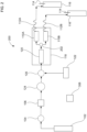
- Figure 1 illustrates a solid liquid extraction apparatus 100 to extract an analyte from a sample with gas assistance, which does not fall within the scope of the claims.
- Apparatus 100 may include a compressed gas source 102, a gas valve 104, a check valve 106, a six port valve 124, a fluid junction 126, a liquid solvent pump 122, a solvent equilibration chamber 120, a sample container 110, a restriction tube 112, a collection bottle 116, and a microprocessor 308.
- Compressed gas source 102 can be fluidically connected to supply a gas to sample container 110.
- Liquid solvent pump 122 can be fluidically connected to supply a liquid solvent to sample container 110.
- Sample container 110 can be configured to contain the solid sample.
- Sample container 110 can be fluidically connected to collection bottle 116 to allow the transfer of the liquid solvent containing the dissolved analyte and the gas.
- An output of compressed gas source 102 can also be fluidically connected to gas valve 104, check valve 106, six port valve 124, fluid junction 126, and solvent equilibration chamber 120.
- Compressed gas source 102 can be configured to supply a gas at a superatmospheric pressure.
- superatmospheric pressure refers to a pressure that is greater than an ambient pressure surrounding an external portion of apparatus 100.
- a typical ambient pressure, in which the extraction apparatus may be used may range from about 94.5 kPa (13.7 PSI) to about 104.8 kPa (15.2 PSI).
- the superatmospheric pressure may be less than about 13 789 kPa (2000 PSI), and preferably be less than about 689 kPa (100 PSI).
- compressed gas source 102 may be in the form of a mechanical gas pump coupled to an air reservoir and configured to provide pressurized air.
- Gas valve 104 is configured to control the flow rate of the gas from compressed gas source 102. The applied superatmospheric pressure may be measured at gas valve 104.
- Gas check valve 106 is configured to prevent a backflow of liquid solvent into compressed gas source 102.
- Six port valve 124 is configured to either allow the flow of gas to sample container 110 or to stop the flow of gas. Under certain circumstances, where only liquid solvent flow is directed to sample container 110, six port valve 124 can stop the flow of gas to sample container 110.
- liquid solvent pump 122 can be fluidically connected to fluid junction 126.
- Liquid solvent pump 122 can be configured to transport the liquid solvent at a pressure that is less than 689 kPa (100 PSI).
- liquid solvent pump 122 may be in the form of a high pressure liquid chromatography (HPLC) pump.
- HPLC high pressure liquid chromatography
- liquid solvent pump 122 may be in the form of a compressed gas source coupled to a liquid solvent reservoir.
- the source of compressed gas may come from compressed gas source 102 where it is used to provide the gas for extraction and also to pump the liquid solvent from the liquid solvent reservoir.
- it is also possible to use two compressed gas sources where a second compressed gas cylinder can be used to pump the liquid solvent from the liquid solvent reservoir.
- liquid solvents suitable for use in the extraction method described herein may be methanol, ethanol, isopropanol, hexane, dichloromethane, and combinations thereof.
- Liquid solvent(s) may be selected that have a polarity similar to the analyte of interest.
- Fluid junction 126 can be configured to mix the gas from compressed gas source 102 and the liquid solvent from the liquid solvent pump 122.
- Fluid junction 126 can include a first inlet, a second inlet, and an outlet, where the first inlet and second inlet are both fluidically connected to the outlet.
- the first inlet can be in fluidic communication with compressed gas source 102.
- the second inlet can be in fluidic communication with liquid solvent pump 122.
- the outlet can be configured to flow a mixture of the gas and the liquid solvent at the same time into an inlet of sample container 110.
- Fluid junction 126 may be in the form of a Tee junction.
- Liquid solvent may be heated to extract the analyte from the solid sample in a variety of ways.
- Solvent equilibration chamber 120 can be configured to heat the liquid solvent to an elevated temperature before the liquid solvent is added to the sample container 110.
- a temperature controller 118 can be configured to heat solvent equilibration chamber 120 and/or sample container 110 to a value greater than ambient.
- Temperature controller 118 can be referred to as a heating source and may be in the form of a microwave device, an electrically resistive device, an infrared device, a convection heater, or a combination thereof. In an apparatus as illustrated in Figure 1 , temperature controller 118 can be used to control the temperature of the liquid solvent at solvent equilibration chamber 120 and also at sample container 110.
- temperature controller 118 can be used to control the temperature of solvent equilibration chamber 120 and not for sample container 110.
- sample container 110 may include an insulated jacket to prevent significant cooling of the heated liquid solvent.
- temperature controller 118 can be used to control the temperature of sample container 110 and not for solvent equilibration chamber 120. The heating of sample container 110 can, in turn, heat the liquid solvent for the extraction.
- Restriction tube 112 can have a relatively small inner bore diameter to generate a backpressure.
- restriction tube 112 can be configured to generate a backpressure of about 69 kPa (10 PSI). It is noted that although pressures are typically measured at gas valve 104, the pressure within sample container 110 will be approximately the same as the applied superatmospheric pressure as measured at gas valve 104. Under certain circumstances, the pressure within sample container 110 may be slightly less than the applied superatmospheric pressure due to pressure drops at various locations, but such a decrease will be insignificant. Restriction tube 112 can generate sufficient backpressure to ensure that the solvent remains in a liquid state at the extraction temperature.
- restriction tube 112 is not fluidically connected to sample container 110, then the liquid solvent can evaporate more significantly, and as a result, cause a reduction in the extraction efficiency. After liquid solvent containing dissolved analyte flows through restriction tube 112, it can be transferred to a collection bottle 116. Collection bottle 116 may include a vent 114 so that gas can egress.
- Microprocessor 308 can be used to control the operation of apparatus 100. Microprocessor 308 may either be integrated into apparatus 100 or be part of a personal computer that communicates with apparatus 100. Microprocessor 308 may be configured to communicate with one or more components of apparatus 100 such as gas valve 104, a check valve 106, six port valve 124, liquid solvent pump 122, and temperature controller 118. For example, microprocessor 308 can control the flow rate, pressure, temperature, and duration of the gas and liquid solvent flow. In an embodiment, microprocessor 308 can control six port valve 124 to stop the flow of gas so that only liquid solvent flows to sample container 110 as a control experiment. In addition, microprocessor 308 can turn off liquid solvent pump 122 to allow only gas to flow when purging sample container 110.
- Figure 2 illustrates a first embodiment of an apparatus 200 that uses a parallel extraction mode to extract an analyte from two solid samples with gas assistance.
- Apparatus 200 is similar to apparatus 100 except that apparatus 200 includes two sample containers 110A and 110B, two restriction tubes 112A and 112B; and two collection bottles 116A and 116B.
- Apparatus 200 may also includes a second fluid junction 202 that is fluidically connected to solvent equilibration chamber 120 and sample containers 110A and 110B.
- Second fluid junction 202 may be in the form of a Tee valve.
- first sample container 110A and second sample container 110B may both be fluidically connected to the outlet of the second fluid junction 202.
- Apparatus 200 is configured to evenly split the flow of the liquid solvent mixture into sample containers 110A and 110B.
- the gas and liquid solvent mixture should input into both sample containers at the same time. It should be noted that the description of two sample containers for use with apparatus 200 is exemplary and should not be construed as being limited to only two sample containers.
- the parallel extraction mode as described herein can be applied to two or more sample containers so that multiple solid sample extractions can be performed at the same time.
- Figure 3 illustrates an apparatus that uses an alternating segmented flow of a gas and then a liquid solvent to extract an analyte from a solid sample, which does not fall within the scope of the claims.
- Apparatus 300 is configured to alternate as a function of time a segmented flow of either a gas or a liquid solvent flow to sample container 110.
- Apparatus 300 is similar to apparatus 100 except that apparatus 300 includes a six port valve 302.
- Six port valve 302 can include an inlet 304 and an outlet 306.
- Six port valve 302 can be configured to allow either a gas flow or a liquid solvent flow in an alternating manner.
- six port valve 302 may include a first position and a second position.
- the first position can direct the liquid solvent from liquid solvent pump 122 into sample container 110.
- the second position can direct the gas from compressed gas source 102 into sample container 110 to establish a superatmospheric pressure P.
- Six port valve 302 can be coupled to microprocessor 308 to alternate between the first position over a first time period for liquid solvent flow and the second position over a second time period for gas flow.
- a ratio of the first time period divided by the second time period may include a value less than about 15.
- a result of having the ratio less than 15 is that the total volume of liquid solvent used in the extraction is relatively low.
- microprocessor 308 may be configured to turn on and off the power to liquid solvent pump 122 to control part of the alternating segmented flow.
- Microprocessor 308 may be configured to turn on and off the gas flow by controlling one of the valves 104, 124, and 302.
- Figure 4 illustrates a solid liquid extraction apparatus 400 to extract an analyte from a sample with gas assistance, which does not fall within the scope of the claims.
- Apparatus 400 is similar to apparatus 100 except that apparatus 400 does not include a fluid junction 126. Instead, apparatus 400 includes a solvent equilibration chamber 120 with two inlets. As illustrated in Figure 4 , solvent equilibration chamber 120 includes a first inlet configured to receive the liquid solvent and a second inlet configured to receive the gas. Solvent equilibration chamber 120 of apparatus 400 can perform a similar mixing function as fluid junction 126 of apparatus 100.
- sample container 110 can include a first inlet configured to receive the liquid solvent and a second inlet configured to receive the gas (not shown).
- examples of the solid liquid extraction apparatus described herein may include a means for providing a mixture of the liquid solvent and gas to the sample container.
- the means for providing a mixture of the liquid solvent and gas to the sample container may include the use of fluid junction 126 of Figure 1 , dual inlets on solvent equilibration chamber 120 of Figure 4 , or dual inlets on the sample container.
- the method includes adding a solid sample to sample container 110.
- the solid sample is weighed before putting it into sample container 110.
- a mixture of a liquid solvent and a gas can be added to the sample container.
- the addition of gas can be controlled to establish a superatmospheric pressure P within sample container 110.
- the liquid solvent can be heated to an elevated temperature T that is below the boiling temperature of the liquid solvent. Either the pressure P or the temperature T should be maintained below the critical point of the gas.
- the analyte from the solid sample can then dissolve into the liquid solvent.
- at least a portion of the liquid solvent can be removed from sample container 110.
- the portion of liquid solvent containing the dissolved analyte can be analyzed with an analytical instrument to determine the amount of analyte present in the solid sample. For example, where a separation of the analyte from other chemicals present in the liquid solvent is needed, liquid or gas chromatography may be performed.
- a detector may be used alone or in combination with the separation process. Exemplary detectors may be a mass spectrometer, ultraviolet-visible spectrometer, a fluorescence spectrometer, a flame ionization detector, a charged aerosol detector, an electrochemical detector, a conductometric detector, a charge detector, or a combination thereof. Details regarding the charged aerosol detector can be found in US Patent No.'s 6,544,484; and 6,568,245 . Details regarding the charge detector that is based on a charged barrier and two electrodes can be found in US Pre-Grant Publication No. 20090218238 .
- the gas is added so that the pressure in the sample container is less than about 13 789 kPa (2000 PSI), and is preferably less than about 689 kPa (100 PSI).
- the liquid solvent may be heated to an elevated temperature that ranges from about 30 °C to about 300 °C.
- the elevated temperature is a temperature value greater than an ambient temperature.
- the ambient temperature may refer to an environmental temperature that is surrounding an external portion of apparatus 100 when the extraction process is performed. Where apparatus 100 is used in an outside environmental setting, the ambient temperature may range from about 5 °C to about 45 °C.
- the liquid solvent may be heated to a temperature greater than ambient before adding the gas and liquid solvent mixture to sample container 110.
- the mixture of gas and liquid solvent may be heated once it is added to sample container 110.
- the added gas should be selected so that it will not transition to a supercritical fluid or a liquid state over the above described pressure and temperature ranges.
- the selected gas is a substance that remains in a distinct gas phase at the operating conditions of the extraction process conditions described herein, i.e., the selected gas does not condense into the liquid phase, and is maintained at a temperature and a pressure below its critical point such that it does not take the form a supercritical fluid.
- the critical point refers to a characteristic temperature and the pressure above which distinct liquid and gas phases do not exist. It should be noted that the critical temperature and the critical pressure are intrinsic properties of a particular gas.
- the gas may be an inert gas such as helium, neon, argon, or combinations thereof.
- gases suitable for use in the embodiments described herein may also include nitrogen, carbon dioxide, air, hydrogen, oxygen, or combinations thereof.
- the added gas causes the pressure to increase in the sample container and increases the boiling point of the liquid solvent.
- a particular combination of pressure and temperature can be selected so that the liquid solvent does not boil.
- the elevated temperature facilitates the dissolution of analyte into the liquid solvent from the solid sample.
- the pressure can prevent the liquid solvent from boiling, and thus, maintains and enhances the solvating ability of the liquid solvent. When the liquid solvent boils, this can decrease the amount of liquid solvent available to dissolve the analyte.
- the adding of the mixture of gas and liquid may be an essentially continuous flow through sample container 110.
- the mixture of the gas and the liquid solvent can be created by adding the gas at a first flow rate and by adding the liquid solvent at a second flow rate.
- the ratio of the first flow rate to the second flow rate may range from about 0.01 to about 5000, and preferably range from about 1.1 to about 5000. It should be noted that the pressure of the gas is based on the input at valve 104.
- the addition of gas can increase the diffusion of the liquid solvent to and from the solid sample, which in turn, provides assistance in the extraction process.
- the diffusion of the gas phase can be several orders higher than the liquid solvent phase.
- the gas addition increases the overall mass transfer properties of the liquid solvent even though the gas by itself does not dissolve the analyte.
- Similac ® Advance ® infant formula was from Abbot Laboratories (Columbus, Ohio). Fritos ® corn chips were from Frito-Lay (Plano, Texas). The parmesan cheese was from Kraft Foods (Northfield, Illinois). Pillsbury ® cake mix was from Pillsbury, Minnesota. The diatomaceous earth absorbent (ASE Prep DE) was from Thermo Scientific Dionex (Sunnyvale, California).
- liquid solvent pump 122 was a high pressure liquid chromatography (HPLC) pump from Thermo Scientific Dionex (part number P680A DGP-6, Sunnyvale, California).
- Compressed gas source 102 was a nitrogen gas cylinder from Airgas-NCN (Sacramento, California) with an adjustable pressure regulator valve 104. The nitrogen flow was measured with a Mass Trak flow meter (Sierra Instruments, Monterey, California, Model 810C-DR-13).
- Check valve 106 was obtained from Upchurch Scientific/IDEX Corp (CV-3001 and U-469, check valve inline cartridge and cartridge holder, Oak Harbor, Washington).
- a 6 port valve 124 (Rheodyne, model 1505, Upchurch Scientific/IDEX Corp, Oak Harbor, Washington) was connected to the gas stream by using Green PEEK tubing (0.0762 cm (0.03 inch) inner diameter).
- the purpose of the 6 port valve was to route the gas for the gas assisted solvent extraction and for the nitrogen purge. In one position the gas flowed for either purging purposes or for mixing with the flow of liquid solvent. In a second position, the gas flow was blocked where the extraction proceeded without gas assistance.
- Temperature controller 118 was a column temperature controller from Pickering Laboratories (CHX700, Mountain View, California).
- Solvent equilibration chamber 120 was a stainless steel solvent column (4.6 x 250 mm, volume of 4.15 mL, Isolation Technologies, IDEX Health and Science, Middleboro, Massachusetts).
- Sample container 110 was a stainless steel sample column (7.8 x 75 mm, volume of 3.58 mL, Isolation Technologies, IDEX Health and Science, Middleboro, Massachusetts). As illustrated in Figure 1 , solvent equilibration chamber 120 and sample container 110 were both incorporated into temperature controller 118. Solvent equilibration chamber 120 and sample container 110 were connected using stainless steel tubing (0.0762 cm (0.03 inch) I.D.) inside the column holder.
- Restriction tube 112 was a stainless steel tube with a 0.0254 cm (0.01 inch) inner diameter X 9.9822 cm (3.93 inch) length.
- Red PEEK tubing 0.0127 cm (0.005 inch) inner diameter X 7.62 cm (3 inch) length
- the generated backpressure caused by the nitrogen gas was approximately 69 kPa (10 PSI) at a 0.6 mL/min liquid solvent flow.
- Collection bottle 116 was obtained from Thermo Scientific Dionex (250 mL, clear collection bottle, PIN 056284).
- a sample container included a stainless steel column (7.8 mm x 75 mm, volume of 3.58 mL, Isolation Technologies, IDEX Health and Science, Middleboro, Massachusetts). The sample container was assembled by first placing a bottom frit and end cap, followed by the addition of the ground DE and solid food sample to the inside portion of the container. Next, a top end cap with a frit was assembled to complete the assembly of sample container 110.
- Temperature controller 118 was thermally equilibrated to a 100 °C.
- Sample container 110 containing the solid sample was loaded into apparatus 100.
- a liquid solvent of hexane, dichloromethane, and methanol (volume ratio of 5:2:1) was flowed through sample container 110 at a flow rate of about 0.5 mL/min for about 30 minutes.
- Compressed gas source 102 was turned on to output nitrogen gas at a flow rate ranging from about 0.17 to 0.20 standard liters per minute (SLPM) to establish a pressure ranging from about 207 kPa (30 PSI) to about 414 kPa (60 PSI). The gas was flowed through sample container 110 at the same time as the liquid solvent.
- SLPM standard liters per minute
- sample container 110 was allowed to depressurize for at least a two minute period. Sample container 110 was then disconnected so that another solid sample could be loaded and then extracted. The liquid solvent containing the dissolved lipids was collected in 250 mL collection bottles. The amount of lipids was then determined gravimetrically and compared to the amount listed on the packaging label.
- Table 1 Liquid Solvent Flow Rate, mL/min N 2 Gas Pressure, kPa (PSI) Lipid Recovery,% Solvent Collected Post Extraction, mL 0.50 0(0) 88.2 13 0.50 207 (30) 86.0 13 0.50 276 (40) 92.9 13 0.50 310 (45) 93.8 12 0.50 345 (50) 94.1 11 0.50 379 (55) 94.8 11 0.50 414 (60) 95.8 10 0.50 483 (70) 96.5 9 0.50 621 (90) 96.5 7
- the nitrogen gas pressure was found to have an effect on the lipid recovery percentage where increasing the gas pressure improved the recovery percentage.
- a zero kPa (zero PSI) nitrogen gas pressure provided a lipid recovery of 88.2% as opposed to a lipid recovery of 96.5% at a 483 kPa (70 PSI) nitrogen gas pressure.
- zero kPa (zero PSI) nitrogen gas refers to the condition where no nitrogen gas was added to the sample container. For this situation where nitrogen gas is not added, the sample container can have a pressure higher than ambient due to pressure induced by the heated solvent.
- Example 2 was performed in a manner similar to Example 1 using infant baby formula as the solid sample with a liquid solvent flow duration of 30 minutes at 100 °C.
- the extraction process was also evaluated where the gas pressure applied to sample container 110 was either zero or 414 kPa (zero or 60 PSI) of nitrogen.
- Table 2 shows the lipid recovery percentage and the volume of liquid solvent collected where the liquid solvent flow rate was varied from 0.25 mL/min to 1.5 mL/min.
- the gas assisted mode not only reduces solvent usage, but also improves the sensitivity via concentrating the analyte of interest.
- the solvent evaporation step can be eliminated since the sample in the gas assisted extraction case is already concentrated.
- a more efficient extraction process was developed that uses a lower flow rate, and in turn, a smaller volume of liquid solvent, with a combination of a modest temperature (less than 300 °C) and pressure (less than 689 kPa (100 PSI)).
- Example 3 was performed in a manner similar to Example 1 using infant baby formula as the solid sample with a liquid solvent flow rate of 0.6 mL/min and a temperature of 100 °C. In this Example, the extraction process was also evaluated where the gas pressure applied to sample container 110 was either zero or 414 kPa (zero or 60 PSI) of nitrogen. Table 3 shows the lipid recovery percentage and the volume of liquid solvent collected where the duration of the liquid solvent flow was varied from 10 minutes to 30 minutes.
- the gas assisted mode not only reduces solvent usage and improves the sensitivity via concentrating the analyte of interest, but it also performs the extraction in a faster time frame. In general, more solid samples can be processed with the extraction apparatus when the extraction time is faster.
- Example 4 was performed in a manner similar to Example 1 using infant baby formula as the solid sample with a liquid solvent flow rate of either 0 mL/min or 0.6 mL/min at 100 °C.
- the gas pressure applied to sample container 110 was varied from abut zero to about 3 447 kPa (500 PSI) nitrogen.
- the liquid solvent flow rate was zero, about 10 mL of liquid solvent was placed in sample container 110 to aid in the extraction of the lipids.
- Table 4 shows the lipid recovery percentage and the volume of liquid solvent collected where the liquid solvent flow was either zero or 0.6 mL/min.
- Example 5 was performed in a manner similar to Example 1 using infant baby formula as the solid sample with either nitrogen, air, or helium as a type of gas for the compressed gas source.
- the added gas pressure and liquid solvent temperature were at 414 kPa (60 PSI) and 100 °C, respectively.
- the liquid solvent flow rate was 0.6 mL/min for a duration of 30 minutes. Table 5 shows the effect of gas type on lipid recovery percentage and volume of collected liquid solvent.
- Example 6 was performed using apparatus 200 with infant baby formula as the solid sample with a liquid solvent flow rate of 1.2 mL/min for a duration of 30 minutes at 100 °C.
- Hexane: dichloromethane: methanol with a volume ratio of 5:2:1 was used as the liquid solvent.
- the nitrogen pressure that was applied was either zero or 414 kPa (zero PSI or 60 PSI). Where nitrogen gas was used, the gas and liquid solvent were flowed at the same time.
- Fluid junction 126 was used to split the mixture of gas and liquid solvent.
- this experiment extracted analyte from two separate sample containers 110A and 110B at the same time.
- Table 6 shows the lipid recovery percentage and the volume of liquid solvent collected where the nitrogen gas flow was tested at zero and 414 kPa (zero and 60 PSI). Note that Sample-1 corresponded to the extraction of first sample container 110A and Sample-2 corresponded to the extraction of second sample container 110B, which were extracted at the same time increasing sample throughput. Table 6 0 kPa (0 PSI) Nitrogen Gas 414 kPa (60 PSI) Nitrogen Gas Parallel Extraction Lipid Recovery,% Solvent Collected Post Extraction, mL Lipid Recovery,% Solvent Collected Post Extraction, mL Sample-1 92.1 14 100.7 13 Sample-2 92.2 19 100.6 15
- the volume difference in liquid solvent delivered to the two sample containers was 5 mL (19 mL - 14 mL) as compared to the volume difference at 414 kPa (60 PSI), which was 2 mL (15 mL - 13 mL).
- This data shows that it was easier to split the gas-liquid solvent stream rather than the liquid solvent stream by itself with no added nitrogen gas.
- the liquid solvent pump by itself is responsible for transporting the liquid solvent to the sample containers and does not split the liquid solvent flow evenly past the fluid junction.
- the improved liquid solvent splitting using gas assistance was due to the high diffusion of the gas medium that enables facile splitting of the solvent streams.
- One of the benefits of the gas assisted parallel extraction mode is faster throughput since multiple extractions can be completed at the same time.
- Example 7 was performed in a manner similar to Example 6 except that the collected liquid solvents collected were weighed to provide more accurate volume estimations.
- Table 7 shows the volume of liquid solvent collected in a parallel extraction mode where the nitrogen gas flow was tested at zero and 414 kPa (zero and 60 PSI).
- Table 7 0 kPa (0 PSI) Nitrogen Gas 414 kPa (60 PSI) Nitrogen Gas Channel-1, Solvent Collected Post Extraction, mL Channel-2, Solvent Collected Post Extraction, mL Channel-1, Solvent Collected Post Extraction, mL Channel-2, Solvent Collected Post Extraction, mL 14.39 18.18 15.44 15.54
- FIG. 3 illustrates a simplified schematic of the experimental set-up for the gas assisted extraction in the segmented flow mode.
- the 6 port valve 302 was fitted with a sample loop of 0.20 mL.
- the two modes There were two types of modes to input the liquid solvent or the nitrogen gas.
- the two modes are referred to as the load mode and the inject mode.
- nitrogen gas flowed through nitrogen gas inlet 304 and filled the loop and exited through outlet 306 and liquid solvent was pumped to sample container 110 at 0.60 mL/min for 100 seconds.
- the inject mode a bolus of nitrogen was injected into sample container 110 for about 20 seconds and the liquid solvent flowed through the loop for 20 seconds.
- the two modes switch back and forth for the duration of the 30 minute extraction process.
- a 1 mL bolus of liquid solvent was injected into sample container 110 in the load mode and a 0.2 mL bolus of nitrogen gas at 414 kPa (60 PSI) was injected into sample container 110 in the inject mode.
- nitrogen gas was applied to purge sample container 110 to remove any remaining liquid solvent.
- the extraction temperature was 100 °C and the liquid solvent was hexane: dichloromethane: methanol (5:2:1 volume ratio).
- the solid sample was infant formula and the analyte was lipids. Table 8 shows the lipid recovery percentage and the volume of liquid solvent collected where the gas flow and liquid solvent flow were delivered in an alternating segmented manner.
- Example 9 was performed in a manner similar to Example 1 using a liquid solvent flow duration of 30 minutes and a flow rate of 0.60 mL/min.
- the nitrogen gas pressure applied to sample container 110 was either zero kPa (zero PSI) or 414 kPa (60 PSI).
- the liquid solvent was hexane and was heated to 100 °C. Table 9 shows the lipid recovery percentage and the volume of liquid solvent collected where the solid sample was corn chips.
- Example 10 was performed in a manner similar to Example 1 where the nitrogen gas pressure applied to sample container 110 was either zero kPa (zero PSI) or 414 kPa (60 PSI). However, the liquid solvent flow rate was 0.50 mL/min for a duration of 12 minutes. The liquid solvent was hexane and isopropanol (3:2 volume ratio) and was heated to 100 °C. Table 10 shows the lipid recovery percentage and the volume of liquid solvent collected where the solid sample was parmesan cheese.
- Table 10 indicated excellent lipid recovery using the gas assisted extraction as compared to zero kPa (zero PSI) nitrogen gas.
- the combination of the solvent and the gas stream caused the lipid recovery percentage to increase by about 4%.
- Example 11 was performed in a manner similar to Example 1 where the nitrogen gas pressure applied to sample container 110 was either zero kPa (zero PSI) or 414 kPa (60 PSI), and the liquid solvent flow duration was 30 minutes. However, the liquid solvent flow rate was 0.50 mL/min. The liquid solvent was hexane, dichloromethane, and methanol (5:2:1 volume ratio) and was heated to 100 °C. Table 11 shows the lipid recovery percentage and the volume of liquid solvent collected where the solid sample was cake mix.
- Table 11 indicated excellent lipid recovery using the gas assisted extraction as compared to zero kPa (zero PSI) nitrogen gas.
- the combination of the solvent and the gas stream caused the lipid recovery percentage to increase by about 3%.
- the evaporation of the collected solvent which is a more volatile combination improves the sensitivity via concentrating the analyte of interest in the gas assisted mode.
Landscapes
- Chemical & Material Sciences (AREA)
- Chemical Kinetics & Catalysis (AREA)
- Physics & Mathematics (AREA)
- Health & Medical Sciences (AREA)
- Life Sciences & Earth Sciences (AREA)
- Analytical Chemistry (AREA)
- Biochemistry (AREA)
- General Health & Medical Sciences (AREA)
- General Physics & Mathematics (AREA)
- Immunology (AREA)
- Pathology (AREA)
- Sampling And Sample Adjustment (AREA)
Claims (6)
- Verfahren zum Extrahieren eines Analyten aus zwei oder mehr Proben, das Verfahren umfassend:Hinzufügen jeder der zwei oder mehr Proben zu einem jeweiligen Probenbehälter von zwei oder mehr Probenbehältern parallel (110);Hinzufügen einer Mischung aus einem flüssigen Lösungsmittel und einem Gas in die zwei oder mehr Probenbehälter gleichzeitig, wobei der Fluss des flüssigen Lösungsmittels zwischen den zwei oder mehr Probenbehältern gleichmäßig aufgeteilt ist, wobei das flüssige Lösungsmittel und das Gas in jeden Probenbehälter gleichzeitig fließen, und wobei das Gas durch eine Druckgasquelle (102) zugeführt wird, wobei die Hinzufügung des Gases gesteuert wird, um einen Überdruck P innerhalb des Probenbehälters zu erzeugen;Erhitzen des flüssigen Lösungsmittels auf eine erhöhte Temperatur T, wobei T unter der Siedetemperatur des flüssigen Lösungsmittels bei dem Überdruck P ist, wobei entweder P oder T unter dem kritischen Punkt des Gases gehalten wird, wobei der Überdruck P nicht über etwa 689 kPa (100 Pfund pro Quadratzoll) relativ zu einem Umgebungsdruck ist, wobei das Erhitzen des flüssigen Lösungsmittels bei einer Temperatur T ist, die von etwa 30 °C bis etwa 300 °C reicht, und wobei das Gas bei dem Überdruck P und der Temperatur T nicht in ein überkritisches Fluid oder einen flüssigen Zustand übergeht;Lösen des Analyts aus der Probe in das flüssige Lösungsmittel innerhalb der zwei oder mehr Probenbehälter; undEntfernen mindestens eines Teils des flüssigen Lösungsmittels aus den zwei oder mehr Probenbehältern, wobei im Prinzip der gesamte Analyt aus der Probe extrahiert und in dem flüssigen Lösungsmittel gelöst wird.
- Verfahren nach einem der vorstehenden Ansprüche, wobei das Erhitzen des flüssigen Lösungsmittels vor dem Hinzufügen der Mischung zu den zwei oder mehr Probenbehältern erfolgt.
- Verfahren nach Anspruch 1, wobei das Erhitzen des flüssigen Lösungsmittels durch Erhitzen der zwei oder mehr Probenbehälter erfolgt.
- Verfahren nach einem der vorstehenden Ansprüche, wobei das Hinzufügen der Mischung ein im Wesentlichen kontinuierlicher Fluss durch die zwei oder mehr Probenbehälter ist.
- Verfahren nach einem der vorstehenden Ansprüche, ferner umfassend:
Analysieren des entfernten flüssigen Lösungsmittels mit einem analytischen Instrument, das aus der Gruppe ausgewählt ist, bestehend aus einem Flüssigkeitschromatographen, einem Gaschromatographen, einem Massenspektrometer, einem UV-VIS- Spektrometer, einem Fluoreszenzspektrometer, einem Flammenionisationsdetektor, einem Detektor für geladene Aerosole, einem Ladungsdetektor, der auf einer geladenen Barriere und zwei Elektroden basiert, einem elektrochemischen Detektor, einem konduktometrischen Detektor und einer Kombination davon. - Verfahren nach einem der vorstehenden Ansprüche, wobei sich der Analyt im Wesentlichen nicht in das Gas löst.
Priority Applications (1)
| Application Number | Priority Date | Filing Date | Title |
|---|---|---|---|
| EP23190933.4A EP4246122A3 (de) | 2012-08-30 | 2013-08-30 | Verfahren zur extraktion eines analyten aus einer probe mit gasunterstützung |
Applications Claiming Priority (2)
| Application Number | Priority Date | Filing Date | Title |
|---|---|---|---|
| US13/599,837 US9440166B2 (en) | 2012-08-30 | 2012-08-30 | Method and device to extract an analyte from a sample with gas assistance |
| PCT/US2013/057469 WO2014036376A2 (en) | 2012-08-30 | 2013-08-30 | Method and device to extract an analyte from a sample with gas assistance |
Related Child Applications (1)
| Application Number | Title | Priority Date | Filing Date |
|---|---|---|---|
| EP23190933.4A Division EP4246122A3 (de) | 2012-08-30 | 2013-08-30 | Verfahren zur extraktion eines analyten aus einer probe mit gasunterstützung |
Publications (2)
| Publication Number | Publication Date |
|---|---|
| EP2890469A2 EP2890469A2 (de) | 2015-07-08 |
| EP2890469B1 true EP2890469B1 (de) | 2023-08-23 |
Family
ID=49231612
Family Applications (2)
| Application Number | Title | Priority Date | Filing Date |
|---|---|---|---|
| EP23190933.4A Pending EP4246122A3 (de) | 2012-08-30 | 2013-08-30 | Verfahren zur extraktion eines analyten aus einer probe mit gasunterstützung |
| EP13766421.5A Active EP2890469B1 (de) | 2012-08-30 | 2013-08-30 | Verfahren zur extraktion eines analyten aus einer probe mit gasunterstützung |
Family Applications Before (1)
| Application Number | Title | Priority Date | Filing Date |
|---|---|---|---|
| EP23190933.4A Pending EP4246122A3 (de) | 2012-08-30 | 2013-08-30 | Verfahren zur extraktion eines analyten aus einer probe mit gasunterstützung |
Country Status (4)
| Country | Link |
|---|---|
| US (3) | US9440166B2 (de) |
| EP (2) | EP4246122A3 (de) |
| CN (1) | CN104602780B (de) |
| WO (1) | WO2014036376A2 (de) |
Families Citing this family (22)
| Publication number | Priority date | Publication date | Assignee | Title |
|---|---|---|---|---|
| US11123655B2 (en) | 2013-02-13 | 2021-09-21 | Dionex Corporation | Apparatus for parallel accelerated solvent extraction |
| US20140230910A1 (en) * | 2013-02-20 | 2014-08-21 | Agilent Technologies, Inc. | Split-channel gas flow control |
| EP2950076B1 (de) * | 2014-05-26 | 2017-06-28 | CSEM Centre Suisse d'Electronique et de Microtechnique SA - Recherche et Développement | Tragbares System zur automatischen Vorbereitung flüssiger und/oder fester Proben |
| JP6458504B2 (ja) * | 2015-01-14 | 2019-01-30 | 株式会社島津製作所 | 超臨界流体−液体クロマトグラフとその分析方法 |
| US9739692B2 (en) | 2015-03-27 | 2017-08-22 | Dionex Corporation | Pump-less method and apparatus for solvent extraction from a sample |
| CN106680043B (zh) * | 2016-11-21 | 2020-07-31 | 北京蓝色星语科技有限公司 | 一种生物化学有害因子的扰动取样装置及扰动取样方法 |
| CN121911133A (zh) * | 2017-05-29 | 2026-04-24 | 株式会社岛津制作所 | 成分萃取装置 |
| US10330573B2 (en) * | 2017-07-10 | 2019-06-25 | Cem Corporation | Rapid sample preparation for analytical analysis using dispersive energized extraction |
| CA2997850C (en) * | 2018-03-09 | 2019-02-12 | Mazza Innovation Ltd. | Pressurized solvent extraction of plant biomass feedstocks |
| CN109270226B (zh) * | 2018-11-29 | 2024-04-19 | 江苏省环境科学研究院 | 一种可控条件的有机液体挥发与处理装置 |
| CN110146606B (zh) * | 2019-05-06 | 2020-07-07 | 北京水木滨华科技有限公司 | 一种高压液体组分的预处理方法 |
| CN110596290A (zh) * | 2019-08-05 | 2019-12-20 | 郭治安 | 一种三级色谱快速测定固体样品中有机化合物的方法 |
| CN113899854B (zh) * | 2020-06-22 | 2024-04-26 | 研能科技股份有限公司 | 微量液体检测器 |
| TWI732605B (zh) * | 2020-06-22 | 2021-07-01 | 研能科技股份有限公司 | 微量液體檢測器 |
| CN114264539B (zh) * | 2020-09-16 | 2024-06-28 | 中国烟草总公司郑州烟草研究院 | 溶剂辅助的热解析设备 |
| CN112964820A (zh) * | 2021-02-23 | 2021-06-15 | 郭治安 | 气动固相微萃取色谱在线序列分析设备及萃取方法 |
| CN113342096B (zh) * | 2021-06-01 | 2022-03-15 | 北京市水文地质工程地质大队(北京市地质环境监测总站) | 一种实验室样品源浓液提取设备及使用方法 |
| CN113805614A (zh) * | 2021-09-01 | 2021-12-17 | 中山大学 | 一种臭氧气体的浓度控制系统 |
| CN114618187B (zh) * | 2022-02-28 | 2024-03-22 | 海南红塔卷烟有限责任公司 | 一种用于热重逸出物分析的微瓶萃取装置及方法 |
| CN117309541B (zh) * | 2022-06-16 | 2025-12-23 | 赛默飞世尔(上海)仪器有限公司 | 样品制备系统及通过其从样品中萃取待分析物的方法 |
| CN114894593B (zh) * | 2022-06-16 | 2026-03-31 | 赛默飞世尔(上海)仪器有限公司 | 样品制备系统及通过其从样品中萃取待分析物的方法 |
| WO2025240164A1 (en) * | 2024-05-17 | 2025-11-20 | Dionex Corporation | Methods and devices for streamline extraction, clean-up, and enrichment of target analytes from solid and semi-solid samples |
Citations (1)
| Publication number | Priority date | Publication date | Assignee | Title |
|---|---|---|---|---|
| US7419692B1 (en) * | 1999-10-28 | 2008-09-02 | Xcafe, Llc | Methods and systems for forming concentrated consumable extracts |
Family Cites Families (28)
| Publication number | Priority date | Publication date | Assignee | Title |
|---|---|---|---|---|
| GB273307A (en) * | 1926-06-25 | 1928-04-05 | Wacker Chemie Gmbh | Apparatus for cleansing metals from oil and other impurities |
| US3117084A (en) * | 1958-05-10 | 1964-01-07 | Bayer Ag | Means for concentrating suspensions |
| SE414872B (sv) * | 1977-10-03 | 1980-08-25 | Bifok Ab | Forfarande och anordning vid flodesinjektionsextraktion |
| US4276315A (en) | 1979-02-12 | 1981-06-30 | General Foods Corporation | Method for decaffeinating coffee |
| US4246291A (en) | 1979-03-26 | 1981-01-20 | General Foods Corporation | Decaffeination of aqueous extracts |
| US4840730A (en) * | 1986-07-25 | 1989-06-20 | Sepragen Corporation | Chromatography system using horizontal flow columns |
| US4832577A (en) * | 1987-07-27 | 1989-05-23 | Avramidis Anestis S | Vortex pump |
| US5338575A (en) | 1990-01-10 | 1994-08-16 | Kohiensaure-werke Rud. Buse GmbH & Co. | Process for the quasi-continuous decaffeination of raw coffee |
| US5147538A (en) | 1990-04-19 | 1992-09-15 | Electric Power Research Institute, Inc. | Field-portable apparatus and method for analytical supercritical fluid extraction of sorbent materials |
| US5372716A (en) * | 1991-02-28 | 1994-12-13 | Suprex Corporation | Supercritical fluid extraction coupled to analytical chromatography system |
| US5281732A (en) * | 1991-12-31 | 1994-01-25 | University Research & Marketing | Solvent extraction of oil from oil-bearing materials |
| US5843311A (en) | 1994-06-14 | 1998-12-01 | Dionex Corporation | Accelerated solvent extraction method |
| US5660727A (en) * | 1994-06-14 | 1997-08-26 | Dionex Corporation | Automated analyte supercritical fluid extraction apparatus |
| US5549819A (en) | 1995-01-17 | 1996-08-27 | Hewlett-Packard Company | Portable extraction instrument |
| WO2000078447A1 (en) | 1999-06-18 | 2000-12-28 | Tsi Incorporated | Aerosol charge adjusting apparatus employing a corona discharge |
| US6425284B1 (en) | 2000-03-08 | 2002-07-30 | Dionex Corporation | Method and apparatus for gas-assisted suppressed chromatography |
| US6568245B2 (en) | 2001-03-15 | 2003-05-27 | Tsi Incorporated | Evaporative electrical detector |
| US7008528B2 (en) * | 2001-03-22 | 2006-03-07 | Mitchell Allen R | Process and system for continuously extracting oil from solid or liquid oil bearing material |
| US6648609B2 (en) * | 2002-04-05 | 2003-11-18 | Berger Instruments, Inc. | Pump as a pressure source for supercritical fluid chromatography involving pressure regulators and a precision orifice |
| US7964224B2 (en) | 2004-03-03 | 2011-06-21 | Beavers Randy L | Process for extraction and standardization of pharmaceutical quality tinctures and extracts from herbal products |
| US20050266130A1 (en) | 2004-05-28 | 2005-12-01 | Henry Aoki | Method for solidification and storing of components extracted from plant, animal, or mineral matter and extract components extracted from held plant, animal, or mineral matter |
| GB2446596A (en) | 2007-02-14 | 2008-08-20 | Ineos Fluor R T & E | Biomass extraction apparatus |
| US7964411B2 (en) | 2007-06-12 | 2011-06-21 | Dionex Corporation | Membrane based concentrators |
| US8293099B2 (en) | 2008-02-28 | 2012-10-23 | Dionex Corporation | Ion detector and system |
| US20090221079A1 (en) | 2008-02-28 | 2009-09-03 | Dionex Corporation | Sample pretreatment and extraction |
| CN201632088U (zh) | 2009-04-09 | 2010-11-17 | 上海化工研究院 | 一种固-液快速萃取装置 |
| DE102009020745A1 (de) | 2009-05-11 | 2010-11-25 | Chemische Fabrik Budenheim Kg | Phosphatgewinnung auf Klärschlamm |
| CN202136830U (zh) | 2011-06-07 | 2012-02-08 | 大连海尔思科技有限公司 | 一种超声波提取装置 |
-
2012
- 2012-08-30 US US13/599,837 patent/US9440166B2/en active Active
-
2013
- 2013-08-30 CN CN201380045584.8A patent/CN104602780B/zh active Active
- 2013-08-30 EP EP23190933.4A patent/EP4246122A3/de active Pending
- 2013-08-30 WO PCT/US2013/057469 patent/WO2014036376A2/en not_active Ceased
- 2013-08-30 EP EP13766421.5A patent/EP2890469B1/de active Active
-
2016
- 2016-08-10 US US15/232,934 patent/US10746639B2/en active Active
- 2016-08-10 US US15/232,897 patent/US10571374B2/en active Active
Patent Citations (1)
| Publication number | Priority date | Publication date | Assignee | Title |
|---|---|---|---|---|
| US7419692B1 (en) * | 1999-10-28 | 2008-09-02 | Xcafe, Llc | Methods and systems for forming concentrated consumable extracts |
Also Published As
| Publication number | Publication date |
|---|---|
| US9440166B2 (en) | 2016-09-13 |
| WO2014036376A3 (en) | 2014-04-24 |
| EP2890469A2 (de) | 2015-07-08 |
| US20160349159A1 (en) | 2016-12-01 |
| US10571374B2 (en) | 2020-02-25 |
| US10746639B2 (en) | 2020-08-18 |
| EP4246122A2 (de) | 2023-09-20 |
| EP4246122A3 (de) | 2023-11-15 |
| US20140063487A1 (en) | 2014-03-06 |
| CN104602780A (zh) | 2015-05-06 |
| US20160349158A1 (en) | 2016-12-01 |
| WO2014036376A2 (en) | 2014-03-06 |
| CN104602780B (zh) | 2017-06-30 |
Similar Documents
| Publication | Publication Date | Title |
|---|---|---|
| EP2890469B1 (de) | Verfahren zur extraktion eines analyten aus einer probe mit gasunterstützung | |
| Musarurwa et al. | Deep eutectic solvent-based dispersive liquid-liquid micro-extraction of pesticides in food samples | |
| Soares da Silva Burato et al. | Recent advances and trends in miniaturized sample preparation techniques | |
| Fazaieli et al. | Development of organic solvents‐free mode of solidification of floating organic droplet–based dispersive liquid–liquid microextraction for the extraction of polycyclic aromatic hydrocarbons from honey samples before their determination by gas chromatography–mass spectrometry | |
| Hageman et al. | Coupled subcritical water extraction with solid-phase microextraction for determining semivolatile organics in environmental solids | |
| Saraji et al. | Recent developments in dispersive liquid–liquid microextraction | |
| Tay et al. | Recent advances in dispersive liquid-liquid microextraction for pharmaceutical analysis | |
| Lawal et al. | Recent advances in analysis of pesticides in food and drink samples using LPME techniques coupled to GC-MS and LC-MS: a review | |
| Wu et al. | Determination of triazine herbicides in fresh vegetables by dynamic microwave-assisted extraction coupled with homogeneous ionic liquid microextraction high performance liquid chromatography | |
| Wu et al. | Investigation of pH-switchability of hydrophobic deep eutectic solvents for the extraction and preconcentration of triazine herbicides in water samples | |
| Xue et al. | A successive homogeneous liquid-liquid microextraction based on solidification of switchable hydrophilicity solvents and ionic liquids for the detection of pyrethroids and cadmium in drinks | |
| Abbasalizadeh et al. | Riboflavin as a green sorbent in dispersive micro‐solid‐phase extraction of several pesticides from fruit juices combined with dispersive liquid–liquid microextraction | |
| Fei et al. | Freezing-assisted sugaring-out liquid-liquid extraction coupled with LC-MS/MS for quantitative determination of perchlorate in honey | |
| Heydarzadeh et al. | Determination of 2, 4‐dichlorophenoxyacetic acid in environmental and food samples using salt‐assisted liquid‐liquid extraction coupled with micro‐channel and high‐performance liquid chromatography | |
| Altunay et al. | Spectrophotometric determination of chlorpyrifos in foodstuffs after vortex-assisted surfactant-enhanced emulsification microextraction using magnetic deep eutectic solvents: analytical greenness profile | |
| Tan¹ et al. | Sample preparation in the analysis of pesticides residue in food by chromatographic techniques | |
| An | Detection of pesticide residues in soil, water, and food | |
| Chen et al. | Binary–solvent–based ionic–liquid–assisted surfactant‐enhanced emulsification microextraction for the determination of four fungicides in apple juice and apple vinegar | |
| Pirsaheb et al. | Determination of fenvalerate in tomato by ultrasound-assisted solvent extraction combined with dispersive liquid–liquid microextraction | |
| Wasik et al. | Speciation of organometallic compounds of tin, lead, and mercury | |
| Liu et al. | Ultra preconcentration of polycyclic aromatic hydrocarbons in smoked bacon by a combination of SPE and DLLME | |
| Feilden | Update on undertaking extractable and leachable testing | |
| Owczarek et al. | New achievements in the field of extraction of trace analytes from samples characterized by complex composition of the matrix | |
| David | Determination of the oil content of rapeseed by supercritical fluid extraction | |
| Kočí et al. | Extraction of polycyclic aromatic nitrogen heterocycles from spiked soil samples |
Legal Events
| Date | Code | Title | Description |
|---|---|---|---|
| PUAI | Public reference made under article 153(3) epc to a published international application that has entered the european phase |
Free format text: ORIGINAL CODE: 0009012 |
|
| 17P | Request for examination filed |
Effective date: 20150227 |
|
| AK | Designated contracting states |
Kind code of ref document: A2 Designated state(s): AL AT BE BG CH CY CZ DE DK EE ES FI FR GB GR HR HU IE IS IT LI LT LU LV MC MK MT NL NO PL PT RO RS SE SI SK SM TR |
|
| AX | Request for extension of the european patent |
Extension state: BA ME |
|
| DAX | Request for extension of the european patent (deleted) | ||
| STAA | Information on the status of an ep patent application or granted ep patent |
Free format text: STATUS: EXAMINATION IS IN PROGRESS |
|
| 17Q | First examination report despatched |
Effective date: 20190624 |
|
| GRAP | Despatch of communication of intention to grant a patent |
Free format text: ORIGINAL CODE: EPIDOSNIGR1 |
|
| STAA | Information on the status of an ep patent application or granted ep patent |
Free format text: STATUS: GRANT OF PATENT IS INTENDED |
|
| RIC1 | Information provided on ipc code assigned before grant |
Ipc: G01N 1/40 20060101ALI20230215BHEP Ipc: B01D 11/02 20060101AFI20230215BHEP |
|
| INTG | Intention to grant announced |
Effective date: 20230309 |
|
| GRAS | Grant fee paid |
Free format text: ORIGINAL CODE: EPIDOSNIGR3 |
|
| GRAA | (expected) grant |
Free format text: ORIGINAL CODE: 0009210 |
|
| STAA | Information on the status of an ep patent application or granted ep patent |
Free format text: STATUS: THE PATENT HAS BEEN GRANTED |
|
| AK | Designated contracting states |
Kind code of ref document: B1 Designated state(s): AL AT BE BG CH CY CZ DE DK EE ES FI FR GB GR HR HU IE IS IT LI LT LU LV MC MK MT NL NO PL PT RO RS SE SI SK SM TR |
|
| REG | Reference to a national code |
Ref country code: GB Ref legal event code: FG4D |
|
| REG | Reference to a national code |
Ref country code: CH Ref legal event code: EP |
|
| REG | Reference to a national code |
Ref country code: IE Ref legal event code: FG4D |
|
| REG | Reference to a national code |
Ref country code: DE Ref legal event code: R096 Ref document number: 602013084499 Country of ref document: DE |
|
| REG | Reference to a national code |
Ref country code: LT Ref legal event code: MG9D |
|
| REG | Reference to a national code |
Ref country code: NL Ref legal event code: MP Effective date: 20230823 |
|
| REG | Reference to a national code |
Ref country code: AT Ref legal event code: MK05 Ref document number: 1601908 Country of ref document: AT Kind code of ref document: T Effective date: 20230823 |
|
| PG25 | Lapsed in a contracting state [announced via postgrant information from national office to epo] |
Ref country code: GR Free format text: LAPSE BECAUSE OF FAILURE TO SUBMIT A TRANSLATION OF THE DESCRIPTION OR TO PAY THE FEE WITHIN THE PRESCRIBED TIME-LIMIT Effective date: 20231124 |
|
| PG25 | Lapsed in a contracting state [announced via postgrant information from national office to epo] |
Ref country code: IS Free format text: LAPSE BECAUSE OF FAILURE TO SUBMIT A TRANSLATION OF THE DESCRIPTION OR TO PAY THE FEE WITHIN THE PRESCRIBED TIME-LIMIT Effective date: 20231223 |
|
| PG25 | Lapsed in a contracting state [announced via postgrant information from national office to epo] |
Ref country code: SE Free format text: LAPSE BECAUSE OF FAILURE TO SUBMIT A TRANSLATION OF THE DESCRIPTION OR TO PAY THE FEE WITHIN THE PRESCRIBED TIME-LIMIT Effective date: 20230823 Ref country code: RS Free format text: LAPSE BECAUSE OF FAILURE TO SUBMIT A TRANSLATION OF THE DESCRIPTION OR TO PAY THE FEE WITHIN THE PRESCRIBED TIME-LIMIT Effective date: 20230823 Ref country code: PT Free format text: LAPSE BECAUSE OF FAILURE TO SUBMIT A TRANSLATION OF THE DESCRIPTION OR TO PAY THE FEE WITHIN THE PRESCRIBED TIME-LIMIT Effective date: 20231226 Ref country code: NO Free format text: LAPSE BECAUSE OF FAILURE TO SUBMIT A TRANSLATION OF THE DESCRIPTION OR TO PAY THE FEE WITHIN THE PRESCRIBED TIME-LIMIT Effective date: 20231123 Ref country code: NL Free format text: LAPSE BECAUSE OF FAILURE TO SUBMIT A TRANSLATION OF THE DESCRIPTION OR TO PAY THE FEE WITHIN THE PRESCRIBED TIME-LIMIT Effective date: 20230823 Ref country code: LV Free format text: LAPSE BECAUSE OF FAILURE TO SUBMIT A TRANSLATION OF THE DESCRIPTION OR TO PAY THE FEE WITHIN THE PRESCRIBED TIME-LIMIT Effective date: 20230823 Ref country code: LT Free format text: LAPSE BECAUSE OF FAILURE TO SUBMIT A TRANSLATION OF THE DESCRIPTION OR TO PAY THE FEE WITHIN THE PRESCRIBED TIME-LIMIT Effective date: 20230823 Ref country code: IS Free format text: LAPSE BECAUSE OF FAILURE TO SUBMIT A TRANSLATION OF THE DESCRIPTION OR TO PAY THE FEE WITHIN THE PRESCRIBED TIME-LIMIT Effective date: 20231223 Ref country code: HR Free format text: LAPSE BECAUSE OF FAILURE TO SUBMIT A TRANSLATION OF THE DESCRIPTION OR TO PAY THE FEE WITHIN THE PRESCRIBED TIME-LIMIT Effective date: 20230823 Ref country code: GR Free format text: LAPSE BECAUSE OF FAILURE TO SUBMIT A TRANSLATION OF THE DESCRIPTION OR TO PAY THE FEE WITHIN THE PRESCRIBED TIME-LIMIT Effective date: 20231124 Ref country code: FI Free format text: LAPSE BECAUSE OF FAILURE TO SUBMIT A TRANSLATION OF THE DESCRIPTION OR TO PAY THE FEE WITHIN THE PRESCRIBED TIME-LIMIT Effective date: 20230823 Ref country code: AT Free format text: LAPSE BECAUSE OF FAILURE TO SUBMIT A TRANSLATION OF THE DESCRIPTION OR TO PAY THE FEE WITHIN THE PRESCRIBED TIME-LIMIT Effective date: 20230823 |
|
| PG25 | Lapsed in a contracting state [announced via postgrant information from national office to epo] |
Ref country code: PL Free format text: LAPSE BECAUSE OF FAILURE TO SUBMIT A TRANSLATION OF THE DESCRIPTION OR TO PAY THE FEE WITHIN THE PRESCRIBED TIME-LIMIT Effective date: 20230823 |
|
| PG25 | Lapsed in a contracting state [announced via postgrant information from national office to epo] |
Ref country code: LU Free format text: LAPSE BECAUSE OF NON-PAYMENT OF DUE FEES Effective date: 20230830 |
|
| PG25 | Lapsed in a contracting state [announced via postgrant information from national office to epo] |
Ref country code: ES Free format text: LAPSE BECAUSE OF FAILURE TO SUBMIT A TRANSLATION OF THE DESCRIPTION OR TO PAY THE FEE WITHIN THE PRESCRIBED TIME-LIMIT Effective date: 20230823 |
|
| PG25 | Lapsed in a contracting state [announced via postgrant information from national office to epo] |
Ref country code: SM Free format text: LAPSE BECAUSE OF FAILURE TO SUBMIT A TRANSLATION OF THE DESCRIPTION OR TO PAY THE FEE WITHIN THE PRESCRIBED TIME-LIMIT Effective date: 20230823 Ref country code: RO Free format text: LAPSE BECAUSE OF FAILURE TO SUBMIT A TRANSLATION OF THE DESCRIPTION OR TO PAY THE FEE WITHIN THE PRESCRIBED TIME-LIMIT Effective date: 20230823 Ref country code: LU Free format text: LAPSE BECAUSE OF NON-PAYMENT OF DUE FEES Effective date: 20230830 Ref country code: ES Free format text: LAPSE BECAUSE OF FAILURE TO SUBMIT A TRANSLATION OF THE DESCRIPTION OR TO PAY THE FEE WITHIN THE PRESCRIBED TIME-LIMIT Effective date: 20230823 Ref country code: EE Free format text: LAPSE BECAUSE OF FAILURE TO SUBMIT A TRANSLATION OF THE DESCRIPTION OR TO PAY THE FEE WITHIN THE PRESCRIBED TIME-LIMIT Effective date: 20230823 Ref country code: DK Free format text: LAPSE BECAUSE OF FAILURE TO SUBMIT A TRANSLATION OF THE DESCRIPTION OR TO PAY THE FEE WITHIN THE PRESCRIBED TIME-LIMIT Effective date: 20230823 Ref country code: CZ Free format text: LAPSE BECAUSE OF FAILURE TO SUBMIT A TRANSLATION OF THE DESCRIPTION OR TO PAY THE FEE WITHIN THE PRESCRIBED TIME-LIMIT Effective date: 20230823 Ref country code: SK Free format text: LAPSE BECAUSE OF FAILURE TO SUBMIT A TRANSLATION OF THE DESCRIPTION OR TO PAY THE FEE WITHIN THE PRESCRIBED TIME-LIMIT Effective date: 20230823 |
|
| REG | Reference to a national code |
Ref country code: BE Ref legal event code: MM Effective date: 20230831 |
|
| REG | Reference to a national code |
Ref country code: IE Ref legal event code: MM4A |
|
| REG | Reference to a national code |
Ref country code: DE Ref legal event code: R097 Ref document number: 602013084499 Country of ref document: DE |
|
| PG25 | Lapsed in a contracting state [announced via postgrant information from national office to epo] |
Ref country code: IT Free format text: LAPSE BECAUSE OF FAILURE TO SUBMIT A TRANSLATION OF THE DESCRIPTION OR TO PAY THE FEE WITHIN THE PRESCRIBED TIME-LIMIT Effective date: 20230823 Ref country code: MC Free format text: LAPSE BECAUSE OF FAILURE TO SUBMIT A TRANSLATION OF THE DESCRIPTION OR TO PAY THE FEE WITHIN THE PRESCRIBED TIME-LIMIT Effective date: 20230823 |
|
| PLBE | No opposition filed within time limit |
Free format text: ORIGINAL CODE: 0009261 |
|
| STAA | Information on the status of an ep patent application or granted ep patent |
Free format text: STATUS: NO OPPOSITION FILED WITHIN TIME LIMIT |
|
| PG25 | Lapsed in a contracting state [announced via postgrant information from national office to epo] |
Ref country code: IE Free format text: LAPSE BECAUSE OF NON-PAYMENT OF DUE FEES Effective date: 20230830 |
|
| 26N | No opposition filed |
Effective date: 20240524 |
|
| PG25 | Lapsed in a contracting state [announced via postgrant information from national office to epo] |
Ref country code: IE Free format text: LAPSE BECAUSE OF NON-PAYMENT OF DUE FEES Effective date: 20230830 Ref country code: FR Free format text: LAPSE BECAUSE OF NON-PAYMENT OF DUE FEES Effective date: 20231023 Ref country code: SI Free format text: LAPSE BECAUSE OF FAILURE TO SUBMIT A TRANSLATION OF THE DESCRIPTION OR TO PAY THE FEE WITHIN THE PRESCRIBED TIME-LIMIT Effective date: 20230823 |
|
| PG25 | Lapsed in a contracting state [announced via postgrant information from national office to epo] |
Ref country code: BE Free format text: LAPSE BECAUSE OF NON-PAYMENT OF DUE FEES Effective date: 20230831 |
|
| PG25 | Lapsed in a contracting state [announced via postgrant information from national office to epo] |
Ref country code: BG Free format text: LAPSE BECAUSE OF FAILURE TO SUBMIT A TRANSLATION OF THE DESCRIPTION OR TO PAY THE FEE WITHIN THE PRESCRIBED TIME-LIMIT Effective date: 20230823 |
|
| PG25 | Lapsed in a contracting state [announced via postgrant information from national office to epo] |
Ref country code: BG Free format text: LAPSE BECAUSE OF FAILURE TO SUBMIT A TRANSLATION OF THE DESCRIPTION OR TO PAY THE FEE WITHIN THE PRESCRIBED TIME-LIMIT Effective date: 20230823 |
|
| PG25 | Lapsed in a contracting state [announced via postgrant information from national office to epo] |
Ref country code: CY Free format text: LAPSE BECAUSE OF FAILURE TO SUBMIT A TRANSLATION OF THE DESCRIPTION OR TO PAY THE FEE WITHIN THE PRESCRIBED TIME-LIMIT; INVALID AB INITIO Effective date: 20130830 |
|
| PG25 | Lapsed in a contracting state [announced via postgrant information from national office to epo] |
Ref country code: HU Free format text: LAPSE BECAUSE OF FAILURE TO SUBMIT A TRANSLATION OF THE DESCRIPTION OR TO PAY THE FEE WITHIN THE PRESCRIBED TIME-LIMIT; INVALID AB INITIO Effective date: 20130830 |
|
| PGFP | Annual fee paid to national office [announced via postgrant information from national office to epo] |
Ref country code: DE Payment date: 20250714 Year of fee payment: 13 |
|
| PGFP | Annual fee paid to national office [announced via postgrant information from national office to epo] |
Ref country code: GB Payment date: 20250811 Year of fee payment: 13 |
|
| PGFP | Annual fee paid to national office [announced via postgrant information from national office to epo] |
Ref country code: CH Payment date: 20250901 Year of fee payment: 13 |
|
| PG25 | Lapsed in a contracting state [announced via postgrant information from national office to epo] |
Ref country code: TR Free format text: LAPSE BECAUSE OF FAILURE TO SUBMIT A TRANSLATION OF THE DESCRIPTION OR TO PAY THE FEE WITHIN THE PRESCRIBED TIME-LIMIT Effective date: 20230823 |