EP2890302B1 - Ultraschallvolumen-durchflussmessung für eine ablationstherapie - Google Patents
Ultraschallvolumen-durchflussmessung für eine ablationstherapie Download PDFInfo
- Publication number
- EP2890302B1 EP2890302B1 EP13779925.0A EP13779925A EP2890302B1 EP 2890302 B1 EP2890302 B1 EP 2890302B1 EP 13779925 A EP13779925 A EP 13779925A EP 2890302 B1 EP2890302 B1 EP 2890302B1
- Authority
- EP
- European Patent Office
- Prior art keywords
- blood
- ablation
- image
- blood vessels
- ultrasound
- Prior art date
- Legal status (The legal status is an assumption and is not a legal conclusion. Google has not performed a legal analysis and makes no representation as to the accuracy of the status listed.)
- Active
Links
Images


Classifications
-
- A—HUMAN NECESSITIES
- A61—MEDICAL OR VETERINARY SCIENCE; HYGIENE
- A61B—DIAGNOSIS; SURGERY; IDENTIFICATION
- A61B8/00—Diagnosis using ultrasonic, sonic or infrasonic waves
- A61B8/46—Ultrasonic, sonic or infrasonic diagnostic devices with special arrangements for interfacing with the operator or the patient
- A61B8/467—Ultrasonic, sonic or infrasonic diagnostic devices with special arrangements for interfacing with the operator or the patient characterised by special input means
- A61B8/469—Ultrasonic, sonic or infrasonic diagnostic devices with special arrangements for interfacing with the operator or the patient characterised by special input means for selection of a region of interest
-
- A—HUMAN NECESSITIES
- A61—MEDICAL OR VETERINARY SCIENCE; HYGIENE
- A61B—DIAGNOSIS; SURGERY; IDENTIFICATION
- A61B8/00—Diagnosis using ultrasonic, sonic or infrasonic waves
- A61B8/06—Measuring blood flow
-
- A—HUMAN NECESSITIES
- A61—MEDICAL OR VETERINARY SCIENCE; HYGIENE
- A61B—DIAGNOSIS; SURGERY; IDENTIFICATION
- A61B8/00—Diagnosis using ultrasonic, sonic or infrasonic waves
- A61B8/08—Clinical applications
- A61B8/0891—Clinical applications for diagnosis of blood vessels
-
- A—HUMAN NECESSITIES
- A61—MEDICAL OR VETERINARY SCIENCE; HYGIENE
- A61B—DIAGNOSIS; SURGERY; IDENTIFICATION
- A61B8/00—Diagnosis using ultrasonic, sonic or infrasonic waves
- A61B8/48—Diagnostic techniques
- A61B8/483—Diagnostic techniques involving the acquisition of a 3D volume of data
-
- A—HUMAN NECESSITIES
- A61—MEDICAL OR VETERINARY SCIENCE; HYGIENE
- A61B—DIAGNOSIS; SURGERY; IDENTIFICATION
- A61B8/00—Diagnosis using ultrasonic, sonic or infrasonic waves
- A61B8/48—Diagnostic techniques
- A61B8/488—Diagnostic techniques involving Doppler signals
-
- A—HUMAN NECESSITIES
- A61—MEDICAL OR VETERINARY SCIENCE; HYGIENE
- A61B—DIAGNOSIS; SURGERY; IDENTIFICATION
- A61B18/00—Surgical instruments, devices or methods for transferring non-mechanical forms of energy to or from the body
-
- A—HUMAN NECESSITIES
- A61—MEDICAL OR VETERINARY SCIENCE; HYGIENE
- A61B—DIAGNOSIS; SURGERY; IDENTIFICATION
- A61B18/00—Surgical instruments, devices or methods for transferring non-mechanical forms of energy to or from the body
- A61B2018/00315—Surgical instruments, devices or methods for transferring non-mechanical forms of energy to or from the body for treatment of particular body parts
- A61B2018/00529—Liver
-
- A—HUMAN NECESSITIES
- A61—MEDICAL OR VETERINARY SCIENCE; HYGIENE
- A61B—DIAGNOSIS; SURGERY; IDENTIFICATION
- A61B18/00—Surgical instruments, devices or methods for transferring non-mechanical forms of energy to or from the body
- A61B2018/00571—Surgical instruments, devices or methods for transferring non-mechanical forms of energy to or from the body for achieving a particular surgical effect
- A61B2018/00577—Ablation
-
- A—HUMAN NECESSITIES
- A61—MEDICAL OR VETERINARY SCIENCE; HYGIENE
- A61B—DIAGNOSIS; SURGERY; IDENTIFICATION
- A61B34/00—Computer-aided surgery; Manipulators or robots specially adapted for use in surgery
- A61B34/10—Computer-aided planning, simulation or modelling of surgical operations
- A61B2034/101—Computer-aided simulation of surgical operations
- A61B2034/105—Modelling of the patient, e.g. for ligaments or bones
-
- A—HUMAN NECESSITIES
- A61—MEDICAL OR VETERINARY SCIENCE; HYGIENE
- A61B—DIAGNOSIS; SURGERY; IDENTIFICATION
- A61B90/00—Instruments, implements or accessories specially adapted for surgery or diagnosis and not covered by any of the groups A61B1/00 - A61B50/00, e.g. for luxation treatment or for protecting wound edges
- A61B90/36—Image-producing devices or illumination devices not otherwise provided for
- A61B2090/364—Correlation of different images or relation of image positions in respect to the body
-
- A—HUMAN NECESSITIES
- A61—MEDICAL OR VETERINARY SCIENCE; HYGIENE
- A61B—DIAGNOSIS; SURGERY; IDENTIFICATION
- A61B8/00—Diagnosis using ultrasonic, sonic or infrasonic waves
- A61B8/13—Tomography
- A61B8/14—Echo-tomography
-
- A—HUMAN NECESSITIES
- A61—MEDICAL OR VETERINARY SCIENCE; HYGIENE
- A61B—DIAGNOSIS; SURGERY; IDENTIFICATION
- A61B8/00—Diagnosis using ultrasonic, sonic or infrasonic waves
- A61B8/52—Devices using data or image processing specially adapted for diagnosis using ultrasonic, sonic or infrasonic waves
- A61B8/5215—Devices using data or image processing specially adapted for diagnosis using ultrasonic, sonic or infrasonic waves involving processing of medical diagnostic data
- A61B8/5238—Devices using data or image processing specially adapted for diagnosis using ultrasonic, sonic or infrasonic waves involving processing of medical diagnostic data for combining image data of patient, e.g. merging several images from different acquisition modes into one image
- A61B8/5261—Devices using data or image processing specially adapted for diagnosis using ultrasonic, sonic or infrasonic waves involving processing of medical diagnostic data for combining image data of patient, e.g. merging several images from different acquisition modes into one image combining images from different diagnostic modalities, e.g. ultrasound and X-ray
Definitions
- This invention is defined in claim 1 and relates to medical diagnostic ultrasound systems and, in particular, to diagnostic ultrasound systems which provide a measure of blood volume flow for ablation therapy.
- tissue ablation where the diseased tissue is destroyed by application of local tissue heating, cooling, or other means.
- ablation methods in most common use are r.f ablation, microwave ablation, HIFU (high intensity focused ultrasound), and cryo-ablation.
- One of the key steps for successful tissue ablation is to determine, prior to conducting the procedure, the appropriate placement of the ablation probe within the lesion and the duration of treatment.
- Each ablation probe has a treatment region around which the temperature is changed enough to cause cell death. This region is typically called the "burn zone". Fully covering the cancerous lesion with the burn zone ensures that there are no residual cells that could result in recurrence of the cancer.
- This treatment planning involves assessing the size and shape of the target lesion, typically with CT images and, using known information about the available intensity levels of the ablation device, calculating a predicted treatment volume based on selected treatment times and/or the number of separate ablations required to treat the entire lesion.
- One challenge for treatment planning is in situations where the target lesion is close to a blood vessel or vessels, which can occur frequently in, for example, liver ablations. It is common in planning a treatment procedure to identify the location of nearby vessels so that they are not damaged in the conduct of the treatment of the lesion. Damaging or disabling blood vessels which supply blood to healthy organs and tissue is to be avoided.
- the blood flowing through a nearby vessel can have a significant cooling or warming effect (i.e., as a heat sink which conveys thermal treatment energy away from the treatment site) on the tissue, which causes the actual treatment volume to be different from the volume specified by the device manufacturer and used in the treatment plan, and which can ultimately lead to incomplete ablation of the lesion and risk of recurrence of disease.
- a significant cooling or warming effect i.e., as a heat sink which conveys thermal treatment energy away from the treatment site
- Patterson et al demonstrated experimentally in porcine liver in vivo that the presence of blood vessels can alter the diameter of an r.f. ablation treatment volume by up to 200%.
- some imaging companies provide treatment planning applications that allow the larger vessels to be identified in the image data, for example from contrast CT images, and then the treatment plan can be adjusted.
- contrast CT images only show where the vessels are located and not how much blood is flowing through them, it is not possible to accurately predict the cooling effect and hence the treatment plan may still be incorrect.
- US 2012/010479 A1 fails to teach a boundary condition as conferred by the surface shape placement defined in claim 1.
- Cancerous and other benign lesions are especially dangerous due to their rampant growth in the body, rapidly spreading their disease conditions and adversely affecting and crowding healthy organs and tissue. To fuel this rampant growth, these lesions develop their own vasculature which diverts the body's flow of nourishing blood to these lesions. The flow of blood into and out of a cancerous region can also be a contributor to diminishing the thermal effect of ablation energy delivery.
- diagnostic imaging is conducted prior to an ablation procedure to identify blood vessels that are in close proximity to a lesion to be treated with ablative therapy.
- the diagnostic imaging modality can be CT, MR, ultrasound or any other modality capable of visualizing blood vessels.
- a diagnostic ultrasound system is then used at the time of the procedure to obtain 3D ultrasound Doppler data from the identified blood vessels.
- the amount of blood flowing through the identified blood vessels is calculated from the Doppler data such as by integrating the flow velocity over the area of a vessel lumen.
- the amount of blood flow thus measured is used to develop or modify an ablation treatment plan that takes the thermal effects of this blood flow into consideration.
- the blood flow information can be used, for example, to modify the predicted r.f. ablation treatment volume for manual planning, or included as input to an automated treatment planning algorithm that seeks to maximize treatment efficacy.
- the ultrasound transducer has tracking capability, for example using electromagnetic (EM) tracking as provided by the Philips Percunav® system.
- EM electromagnetic
- the reference frame of the ultrasound system is aligned with the corresponding image of the imaging modality used to identify the vessels of interest (e.g., through plane matching or automated methods provided by the image fusion capability of the Percunav system) and, since the transducer location is also known, the Doppler region of interest is placed automatically on the vessels of interest, thus improving accuracy, efficiency and ease of use.
- An ultrasonic diagnostic imaging system constructed for use in accordance with the present invention is shown in block diagram form.
- An ultrasound probe 10 capable of three dimensional imaging includes a two dimensional array transducer 12 which transmits electronically steered and focused beams over a volumetric region and receives single or multiple receive beams in response to each transmit beam.
- Groups of adjacent transducer elements referred to as “patches” or “subarrays” are integrally operated by a microbeamformer ( ⁇ BF) in the probe 12, which performs partial beamforming of received echo signals and thereby reduces the number of conductors in the cable between the probe and the main system.
- ⁇ BF microbeamformer
- the echo signals received by the array elements and microbeamformer in response to a transmit beam are coupled to a system beamformer 18, where the partially beamformed echo signals from the microbeamformer are processed to form fully beamformed single or multiple receive beams in response to a transmit beam.
- a suitable beamformer for this purpose is described in the aforementioned Savord '032 patent.
- the receive beams formed by the beamformer 18 are coupled to a signal processor 26 which performs functions such as filtering and quadrature demodulation.
- the echo signals of the processed receive beams are coupled to a Doppler processor 30 and a B mode processor 24.
- the Doppler processor 30 processes the echo information into spatially resolved Doppler power or velocity information.
- For B mode imaging the receive beam echoes are envelope detected and the signals logarithmically compressed to a suitable dynamic range by the B mode processor 24.
- the echo signals from the volumetric region are buffered in the form of a 3D image dataset 32.
- the 3D image data may be processed for display in several ways. One way is to produce one or more 2D planes of the volume. This is described in U.S.
- planar images are formed by addressing data of the 3D image data set in spatially discrete image planes, known as multi-planar reformatting.
- the three dimensional image data may also be rendered to form a perspective or kinetic parallax 3D display by a volume renderer 36.
- a third way is to produce an "iSlice" image, which is formed by iSlice scan converter 34 from image data of a repetitively scanned plane of the 3D volume. By only scanning one or a few image planes in the volume, the scanning can be done rapidly enough to produce one or more live 2D iSlice images.
- biplane imaging An effective use of iSlice imaging is performed in what is known as biplane imaging, in which two or more iSlice images are concurrently displayed and can be spatially manipulated with respect to each other as described in US Pat. 6,709,394 (Frisa et al. )
- One preferred biplane mode is the rotate mode, in which one iSlice image has a fixed orientation with respect to the probe 10 and a second iSlice image intersects the first at a common central scanline and can be rotated around that scanline.
- the first image provide a spatial reference for the user, and the second image can be rotated to view intersecting planes in the volume.
- Biplane imaging is useful in the practice of the present invention as described below.
- the resulting 2D or 3D images which may be B mode, Doppler or both as described in US patent 5,720,291 (Schwartz ), are coupled to a display processor 38, from which they are displayed on an image display 40.
- a volume flow calculator 60 is coupled to receive selected Doppler flow data from the 3D image data set 32.
- the volume flow calculator calculates volume flow of blood in ml/sec., preferably by integration of the flow data of a surface that intersects a blood vessel as described in US Pat. 6,780,155 (Li et al. ) or US Pat. 6,663,568 (Gil ).
- the volume flow calculation is coupled to the display processor 38 for display on the display 40.
- User control of the beamformer controller 22 and other functions of the ultrasound system are provided through a user interface or control panel 20.
- FIGURE 2 shows ultrasound probe 10 imaging an iSlice image plane 84 of a region of the body such as the liver.
- the probe 10 is connected to the ultrasound system by a cable and strain relief 37.
- the iSlice image displays pathology to be treated by ablation, in this case a lesion 70 in the liver such as an HCC lesion.
- the lesion 70 is seen to be supplied with blood from a surrounding network of vasculature 72.
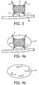
- FIGURE 3 is an enlarged view of the lesion 70 and its vasculature, in this view revealing the presence of a nearby large blood vessel 80.
- the blood vessel 80 is seen to be a source of blood supply for some of the blood vessels of the vasculature 72, although this is not always the situation in a given patient; the large blood vessel 80 may simply be passing through the tissue near the lesion 70.
- the blood vessel 80 is seen to have its closest proximity to the lesion 70 at a point where it is a distance "d" from the lesion.
- FIGURES 4a and 4b illustrate one implementation of the present invention in which the thermal transfer effect of the blood flow to and from the lesion 70 is determined.
- the vasculature nourishing the lesion includes a number of well defined major vessels as illustrated by blood vessels 72 in FIGURE 3
- the volume flow of these vessels can be identified and calculated.
- FIGURE 4a illustrates an ultrasound image of the lesion and its vasculature around which a user has placed an enclosing shape 74.
- the shape 74 is an oval shape which is seen to intersect the major vessels of the blood supply vessels 72.
- the user can use the control panel 20 to select a shape of a desired size and shape from an ROI (region of interest) selector 50.
- the shape is manipulated on the screen from the control panel until it is properly placed to intersect the major vessels as shown in FIGURE 4a .
- the shape 74 in this example is an oval in two dimensions and an ellipsoid in three dimensions.
- the biplane imaging mode is well suited to manipulate the shape 70 around the lesion 70, since the user can view initial placement of the shape 74 in one plane as shown in FIGURE 4a , then view the shape as the other biplane image is rotated about the center of the first image, observing that the shape fully encloses the lesion and intersects its supply vessels. While the present example shows an oval or ellipsoidal shape, other shapes such as a circle, sphere, square or rectangular box, or square cubic or rectangular cubic shape can also be used.
- the shape or a graphic designating the ROI is placed automatically in the ultrasound image by the system if the ultrasound image has been aligned (e.g. by multi-modality image registration) with the reference frame of a pre-procedure planning modality.
- a standard practice in planning an ablation procedure is to first image the pathology by CT or MR imaging. An image in this modality is then analyzed to identify the lesion and its feeding or neighboring blood vessels by a vessel segmentation algorithm.
- a system which performs this analysis is the Extended Brilliance CT workstation available from Philips Healthcare of Andover Massachusetts. This workstation has a CT vessel segmentation algorithm which will automatically mark blood vessels to be quantified on a CT image, which then becomes the CT reference image frame for the procedure.
- a multi-modality image registration system such as an ultrasound system equipped with the Percunav® image fusion option 54 can register the CT reference image with an anatomically matching ultrasound image from the ultrasound 3D dataset. Once aligned, the delineation of the blood vessels marked on the CT image is translated to the ultrasound image, automatically identifying the ROI and/or the vessels to be quantified by ultrasound in the ultrasound image.
- the surface of the enclosing shape 74 intersects the blood vessels passing through it as illustrated in FIGURE 4b .
- Cross-sectional surfaces 76 of the blood vessels are delineated by the shape 74.
- the Doppler flow of blood vessels when separately presented from its surrounding B mode tissue image segments the flow of blood in the vessels as explained in US Pat. 5,474,073 (Schwartz et al. )
- the volume flow of each vessel 72 can be calculated by integration of the Doppler flow values of the flow surfaces 76 that intersects surrounding surface 74.
- the direction of the blood flow is integrated by the relative polarity of the Doppler signals, identifying the flow of fresh (unablated) blood into the lesion 70 and the flow of thermally treated blood away from the lesion.
- By summing the different flow volumes the total volume flow to and from the lesion can be calculated and the net effect on thermal transfer estimated. The effect of this thermal transfer can then be used to plan the ablation treatment.
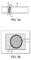
- surface shape 74 used to delineate the flow of the vessel can be a single plane as illustrated in FIGURE 5a .
- the shape 74 is positioned to intersect the flow 82 of the vessel 80 at an orthogonal or other angle as explained in the Li et al. and Gill patents. This intersection will effectively project the Doppler flow 82 of the vessel 80 onto the plane of the shape 74 as illustrated in FIGURE 5b .
- an optional template 94 has been placed around the flow area 82 and the endothelial wall 86 of the lumen of blood vessel 80.
- the blood flow velocity of the Doppler data values of the flow surface 82 is integrated over the flow area to calculate the volume flow rate through the vessel 80 in ml/min.
- the volume flow of the vessel 80 is shown on the screen of display 40 where it can be accessed and used in conjunction with the proximity of the vessel to the treatment site (distance "d" in FIGURE 3 ) and the thermal transport properties of the intervening tissue to plan the ablation therapy of lesion 70.
- a typical ablation planning process may proceed as follows. Planning may be done for a liver r.f. ablation procedure, where an HCC lesion has been previously identified on a contrast CT scan. The clinician would first review this CT study in order to develop a preliminary treatment plan (e.g., deciding on the ablation needle tip location and the nominal r.f. intensity and duration). The clinician may also execute a CT segmentation algorithm, such as one which is commercially available on CT image analysis workstations, that highlights the blood vessels within the liver. Upon identifying a large vessel that is close to the target lesion, the clinician would then understand that this vessel could have a significant effect on the treatment plan.
- the clinician starts scanning with an ultrasound system, the co-ordinates of which had already been registered to the CT co-ordinate system.
- Various methods exist for registering medical diagnostic images including external fiducial-based methods and manual tissue landmark-based methods.
- the Percunav® image fusion option available on the iU22 ultrasound system from Philips Healthcare of Andover, Massachusetts is capable of anatomically registering CT and ultrasound images.
- the clinician By viewing the ultrasound image superimposed on the CT image, including the segmentation of the vessels from the CT data, the clinician would be easily able to target a 3D Doppler ultrasound volume acquisition through the vessel that is close to the target lesion.
- the identification of the 3D Doppler ultrasound volume in the aligned images may also be automated as described previously, based on the treatment plan.
- An algorithm would then calculate the blood volume flowing through this vessel, and this information would then be used to modify the treatment plan and hence adjust the needle placement, r.f. intensity and/or duration.
- a previously acquired CT, MR or 3D ultrasound volume or 3D contrast ultrasound volume may be used as the reference image input to a treatment plan, and for identifying blood vessels near the target lesion.
- ultrasonic automated border detection may be used to identify and delineate the size of blood vessel lumens as described in US Pat. 6,491,436 (Chenal et al. ) The volume flow of the traced blood vessel lumens is then calculated from their size and Doppler flow data.
- the flow-delineating shapes and surfaces may be displayed or not displayed at the choice of the system designer.
- a system for carrying out the method of the present invention can be used in procedures even in cases where pre-procedure treatment planning is not used.
- the lesion and the blood vessels near the lesion are identified with live ultrasound.
- the ablation probe is introduced into the body and guided into the lesion.
- the Percunav® EM tracking system by tracking the location of the probe, provides the ability to display the treatment region (or burn zone) as a graphical overlay around the tip of the ablation probe.
- the ablation device manufacturer's specified burn zone is used as the initial definition of the burn zone, providing the starting shape and size of the burn zone graphic around the probe tip.
- the system may initially show a relatively large burn zone around the probe tip, for instance, which is then modified to show a smaller burn zone once the thermal effect of the nearby blood flow is weighed. The user can then adjust the treatment time or other procedure parameters to fully ablate the target lesion.
Landscapes
- Health & Medical Sciences (AREA)
- Life Sciences & Earth Sciences (AREA)
- Medical Informatics (AREA)
- Biophysics (AREA)
- Nuclear Medicine, Radiotherapy & Molecular Imaging (AREA)
- Pathology (AREA)
- Radiology & Medical Imaging (AREA)
- Engineering & Computer Science (AREA)
- Biomedical Technology (AREA)
- Heart & Thoracic Surgery (AREA)
- Physics & Mathematics (AREA)
- Molecular Biology (AREA)
- Surgery (AREA)
- Animal Behavior & Ethology (AREA)
- General Health & Medical Sciences (AREA)
- Public Health (AREA)
- Veterinary Medicine (AREA)
- Hematology (AREA)
- Vascular Medicine (AREA)
- Ultra Sonic Daignosis Equipment (AREA)
- Surgical Instruments (AREA)
Claims (14)
- Verfahren zur Verwendung von Ultraschallinformationen für die Planung einer Ablationsbehandlung von Pathologie, wobei das Verfahren Folgendes umfasst:Erfassen eines Behandlungsplanungsbilds von der durch Ablation zu behandelnden Pathologie (70) und einem oder mehreren Blutgefäßen (80) in der Nähe der Pathologie;Identifizieren der durch Ablation zu behandelnden Pathologie in einem Ultraschallbild (84);Identifizieren von einem oder mehreren Blutgefäßen (72), die sich in der Nähe der Pathologie befinden, durch Platzieren einer Oberflächenform (74) an einer interessierenden Region in dem Ultraschallbild;Erfassen von dreidimensionalen Ultraschall-Doppler-Daten aus der Blutströmung der identifizierten Blutgefäße durch Erfassen von Ultraschall-Doppler-Daten an einem Schnittpunkt (76) der Strömung von dem einen oder mehreren Blutgefäßen mit der Oberflächenform;Berechnen der durch die identifizierten Blutgefäße strömenden Blutmenge unter Verwendung der Ultraschall-Doppler-Daten; undEntwickeln eines Ablationsbehandlungsplans, der eine Wärmetransporteigenschaft der durch die identifizierten Blutgefäße strömenden Blutmenge berücksichtigt,wobei das Platzieren der Oberflächenform automatisch unter Verwendung der Kenntnis des Orts der Blutgefäße erfolgt, die durch Registrierung des Ultraschallbilds mit dem Behandlungsplanungsbild gewonnen wurde.
- Verfahren nach Anspruch 1, wobei das Erfassen der dreidimensionalen Ultraschall-Doppler-Daten weiterhin das Erfassen von dreidimensionalen Ultraschall-Doppler-Geschwindigkeitsdaten aus der Blutströmung eines identifizierten Gefäßes umfasst.
- Verfahren nach Anspruch 2, wobei das Berechnen der durch ein identifiziertes Blutgefäß strömenden Blutmenge weiterhin das Abgrenzen einer Oberfläche durch die Blutströmung eines Gefäßes und das Integrieren der Strömungsgeschwindigkeitsdaten über eine Fläche der Oberfläche umfasst.
- Verfahren nach Anspruch 1, wobei das Identifizieren von einem oder mehreren Blutgefäßen weiterhin das Identifizieren von einem oder mehreren Blutgefäßen in einem dreidimensionalen Ultraschallbild umfasst.
- Verfahren nach Anspruch 1, wobei das Identifizieren von einem oder mehreren Blutgefäßen weiterhin das Identifizieren von einem oder mehreren Blutgefäßen in zweidimensionalen Zweiebenen-Ultraschallbildern umfasst.
- Verfahren nach Anspruch 1, wobei das Erfassen eines Behandlungsplanungsbilds weiterhin das Erfassen eines CT-Bilds der Pathologie und der Struktur von einem oder mehreren Gefäßen in der Nähe der Pathologie umfasst;
wobei das automatische Platzieren der Oberflächenform weiterhin das anatomische Registrieren eines Ultraschallreferenzbilds mit dem CT-Bild umfasst. - Verfahren nach Anspruch 1, wobei das Platzieren einer Oberflächenform weiterhin das Schneiden von einem oder mehreren Blutgefäßen mit einer dreidimensionalen Form umfasst.
- Verfahren nach Anspruch 1, wobei das Platzieren einer Oberflächenform weiterhin das Schneiden von einem oder mehreren Blutgefäßen mit einer zweidimensionalen Form umfasst.
- Verfahren nach Anspruch 1, wobei das Entwickeln eines Ablationsbehandlungsplans weiterhin das Entwickeln eines Ablationsbehandlungsplans umfasst, der die Volumenblutströmung eines Gefäßes und die Nähe des Gefäßes zu der identifizierten Pathologie berücksichtigt.
- Verfahren nach Anspruch 1, das weiterhin Folgendes umfasst:Verwenden der Wärmetransporteigenschaft der durch die identifizierten Blutgefäße strömenden Blutmenge, um eine grafische Anzeige der Behandlungsregion zu modifizieren.
- Verfahren nach Anspruch 10, wobei das Verwenden der Wärmetransporteigenschaft weiterhin das Verwenden der Wärmetransporteigenschaft der durch die identifizierten Blutgefäße strömenden Blutmenge umfasst, um eine grafische Anzeige der Behandlungsregion im Verhältnis zu einer Ablationsvorrichtung zu modifizieren.
- Verfahren nach Anspruch 11, wobei das Modifizieren einer grafischen Anzeige weiterhin das Modifizieren einer grafischen Anzeige der Größe einer Behandlungsregion im Verhältnis zu einer Wärmetransporteigenschaft umfasst.
- Verfahren nach Anspruch 10, weiterhin umfassend das Identifizieren der durch Ablation zu behandelnden Pathologie in einem Nicht-Ultraschall-Diagnosebild; und
anatomisches Registrieren des Nicht-Ultraschall-Diagnosebilds mit einem Ultraschallbild. - Verfahren nach Anspruch 10, wobei die Ablationsbehandlung weiterhin HF-Ablations-, Mikrowellenablations-, HIFU- oder Kryoablationstherapie umfasst.
Applications Claiming Priority (2)
| Application Number | Priority Date | Filing Date | Title |
|---|---|---|---|
| US201261696156P | 2012-09-01 | 2012-09-01 | |
| PCT/IB2013/056585 WO2014033577A1 (en) | 2012-09-01 | 2013-08-12 | Ultrasonic volume flow measurement for ablation therapy |
Publications (2)
| Publication Number | Publication Date |
|---|---|
| EP2890302A1 EP2890302A1 (de) | 2015-07-08 |
| EP2890302B1 true EP2890302B1 (de) | 2016-08-10 |
Family
ID=49448223
Family Applications (1)
| Application Number | Title | Priority Date | Filing Date |
|---|---|---|---|
| EP13779925.0A Active EP2890302B1 (de) | 2012-09-01 | 2013-08-12 | Ultraschallvolumen-durchflussmessung für eine ablationstherapie |
Country Status (7)
| Country | Link |
|---|---|
| US (1) | US10070846B2 (de) |
| EP (1) | EP2890302B1 (de) |
| JP (1) | JP6088653B2 (de) |
| CN (1) | CN104822326B (de) |
| BR (1) | BR112015004443A2 (de) |
| RU (1) | RU2015111740A (de) |
| WO (1) | WO2014033577A1 (de) |
Families Citing this family (6)
| Publication number | Priority date | Publication date | Assignee | Title |
|---|---|---|---|---|
| US10643371B2 (en) * | 2014-08-11 | 2020-05-05 | Covidien Lp | Treatment procedure planning system and method |
| US10206651B2 (en) * | 2015-09-30 | 2019-02-19 | General Electric Company | Methods and systems for measuring cardiac output |
| CN105476665B (zh) * | 2016-01-27 | 2019-01-25 | 成都思多科医疗科技有限公司 | 一种基于超声的血流速度测量及血流流量测量方法 |
| CN111093516B (zh) * | 2017-11-21 | 2023-01-10 | 深圳迈瑞生物医疗电子股份有限公司 | 用于规划消融的超声系统及方法 |
| WO2019162696A1 (en) * | 2018-02-26 | 2019-08-29 | Ipsen Biopharm Limited | Use of ultrasound to guide injection of non-cytotoxic protease |
| US20250213226A1 (en) * | 2022-05-20 | 2025-07-03 | Koninklijke Philips N.V. | Multi-modality image visualization for stroke detection |
Family Cites Families (25)
| Publication number | Priority date | Publication date | Assignee | Title |
|---|---|---|---|---|
| US5325860A (en) | 1991-11-08 | 1994-07-05 | Mayo Foundation For Medical Education And Research | Ultrasonic and interventional catheter and method |
| US5474073A (en) | 1994-11-22 | 1995-12-12 | Advanced Technology Laboratories, Inc. | Ultrasonic diagnostic scanning for three dimensional display |
| US5720291A (en) | 1996-03-22 | 1998-02-24 | Advanced Technology Laboratories, Inc. | Three dimensional medical ultrasonic diagnostic image of tissue texture and vasculature |
| AUPP227898A0 (en) | 1998-03-11 | 1998-04-09 | Commonwealth Scientific And Industrial Research Organisation | Improvements in ultrasound techniques |
| US6013032A (en) | 1998-03-13 | 2000-01-11 | Hewlett-Packard Company | Beamforming methods and apparatus for three-dimensional ultrasound imaging using two-dimensional transducer array |
| US5997479A (en) | 1998-05-28 | 1999-12-07 | Hewlett-Packard Company | Phased array acoustic systems with intra-group processors |
| US6368281B1 (en) | 1999-07-30 | 2002-04-09 | Rodney J Solomon | Two-dimensional phased array ultrasound transducer with a convex environmental barrier |
| JP3643272B2 (ja) | 1999-10-12 | 2005-04-27 | 大同メタル工業株式会社 | すべり軸受 |
| US6443896B1 (en) | 2000-08-17 | 2002-09-03 | Koninklijke Philips Electronics N.V. | Method for creating multiplanar ultrasonic images of a three dimensional object |
| US6709394B2 (en) | 2000-08-17 | 2004-03-23 | Koninklijke Philips Electronics N.V. | Biplane ultrasonic imaging |
| US6419633B1 (en) | 2000-09-15 | 2002-07-16 | Koninklijke Philips Electronics N.V. | 2D ultrasonic transducer array for two dimensional and three dimensional imaging |
| US6491636B2 (en) | 2000-12-07 | 2002-12-10 | Koninklijke Philips Electronics N.V. | Automated border detection in ultrasonic diagnostic images |
| US6780155B2 (en) | 2001-12-18 | 2004-08-24 | Koninklijke Philips Electronics | Method and system for ultrasound blood flow imaging and volume flow calculations |
| JP4401354B2 (ja) * | 2003-05-19 | 2010-01-20 | 株式会社日立製作所 | 超音波治療装置 |
| US8267927B2 (en) * | 2007-01-24 | 2012-09-18 | Koninklijke Philips Electronics N.V. | Advanced ablation planning |
| US20090177089A1 (en) * | 2008-01-04 | 2009-07-09 | Assaf Govari | Three-dimensional image reconstruction using doppler ultrasound |
| BRPI0914520A2 (pt) * | 2008-11-04 | 2015-12-15 | Koninkl Philips Electronics Nv | meio de armazenamento legível em computador, e, sistema de ablação por ultrassom |
| US8517962B2 (en) | 2009-10-12 | 2013-08-27 | Kona Medical, Inc. | Energetic modulation of nerves |
| US20110092880A1 (en) | 2009-10-12 | 2011-04-21 | Michael Gertner | Energetic modulation of nerves |
| WO2011080666A1 (en) * | 2009-12-30 | 2011-07-07 | Koninklijke Philips Electronics N.V. | Dynamic ablation device |
| CN102232857A (zh) * | 2010-05-06 | 2011-11-09 | 高春平 | 非创伤性聚焦超声冠状动脉体外溶栓系统 |
| EP2387963A1 (de) * | 2010-05-17 | 2011-11-23 | Koninklijke Philips Electronics N.V. | Vorrichtung zur Bestimmung der Temperaturverteilung |
| DE102010041175A1 (de) * | 2010-07-09 | 2012-01-12 | Siemens Aktiengesellschaft | Optimierung der Ablationsplanung durch den Einsatz von Flussinformationen aus Perfusionsmessungen |
| US10034614B2 (en) * | 2012-02-29 | 2018-07-31 | General Electric Company | Fractional flow reserve estimation |
| JP6099748B2 (ja) * | 2012-09-01 | 2017-03-22 | コーニンクレッカ フィリップス エヌ ヴェKoninklijke Philips N.V. | アブレーション計画のための超音波ボリュームフロー測定 |
-
2013
- 2013-08-12 EP EP13779925.0A patent/EP2890302B1/de active Active
- 2013-08-12 BR BR112015004443A patent/BR112015004443A2/pt not_active Application Discontinuation
- 2013-08-12 WO PCT/IB2013/056585 patent/WO2014033577A1/en not_active Ceased
- 2013-08-12 US US14/424,509 patent/US10070846B2/en active Active
- 2013-08-12 JP JP2015529152A patent/JP6088653B2/ja active Active
- 2013-08-12 CN CN201380056853.0A patent/CN104822326B/zh active Active
- 2013-08-12 RU RU2015111740A patent/RU2015111740A/ru not_active Application Discontinuation
Also Published As
| Publication number | Publication date |
|---|---|
| EP2890302A1 (de) | 2015-07-08 |
| JP2015528342A (ja) | 2015-09-28 |
| CN104822326A (zh) | 2015-08-05 |
| US10070846B2 (en) | 2018-09-11 |
| CN104822326B (zh) | 2017-09-15 |
| US20150223779A1 (en) | 2015-08-13 |
| RU2015111740A (ru) | 2016-10-20 |
| BR112015004443A2 (pt) | 2017-07-04 |
| JP6088653B2 (ja) | 2017-03-01 |
| WO2014033577A1 (en) | 2014-03-06 |
Similar Documents
| Publication | Publication Date | Title |
|---|---|---|
| EP2890302B1 (de) | Ultraschallvolumen-durchflussmessung für eine ablationstherapie | |
| EP2621388B1 (de) | System für temperaturrückmeldung für adaptive hf-ablation | |
| RU2492884C2 (ru) | Способ и устройство для отслеживания положения терапевтического ультразвукового преобразователя | |
| RU2519378C2 (ru) | Способ и система для ультразвуковой терапии | |
| EP2584990B1 (de) | System für fokussierte prostatakrebsbehandlung | |
| CN1868409B (zh) | 使用超声系统的束方向显示导管尖 | |
| BRPI1001591A2 (pt) | sistema de terapia e imageamento por ultrassom e método de administração de terapia | |
| US20180028261A1 (en) | Device and method for assisting in tissue ablation | |
| CN107997821A (zh) | 用于计划和导航的系统和方法 | |
| EP2890303B1 (de) | Ultraschalldurchflussmessung zur ablationsplanung | |
| CN115317128A (zh) | 消融模拟方法及设备 | |
| Xu et al. | Three‐dimensional ultrasound image‐guided robotic system for accurate microwave coagulation of malignant liver tumours | |
| Tang et al. | A high-precision US-guided robot-assisted HIFU treatment system for breast cancer | |
| CN112043377B (zh) | Ct任意切面超声视野模拟辅助消融路径规划方法及系统 | |
| WO2015087203A1 (en) | Imaging systems and methods for monitoring treatment of tissue lesions | |
| Collins et al. | Multiphysics modeling toward enhanced guidance in hepatic microwave ablation: a preliminary framework | |
| CN118593111A (zh) | 图像处理方法、装置、系统和存储介质 | |
| Wu et al. | An interactive HIFU therapy planning using simulation & visualization | |
| Morelli et al. | High-intensity focused ultrasound (HIFU) modeling: in vitro validation and integration into patient-specific planning Tool | |
| Chauhan et al. | Intra-operative feedback and dynamic compensation for image-guided robotic focal ultrasound surgery | |
| Evripidou et al. | Workflow of a Preclinical Robotic Magnetic Resonance Imaging-guided Focused Ultrasound Body System | |
| Caskey et al. | Electromagnetically tracked ultrasound for small animal imaging | |
| Bao et al. | Ultrasound-guided ablation system for laparoscopic liver surgery | |
| Zheng et al. | Ultrasound-directed robotic system for thermal ablation of liver tumors: a preliminary report | |
| Peikari | Validation Platform for Ultrasound-Based Monitoring of Thermal Ablation |
Legal Events
| Date | Code | Title | Description |
|---|---|---|---|
| PUAI | Public reference made under article 153(3) epc to a published international application that has entered the european phase |
Free format text: ORIGINAL CODE: 0009012 |
|
| 17P | Request for examination filed |
Effective date: 20150401 |
|
| AK | Designated contracting states |
Kind code of ref document: A1 Designated state(s): AL AT BE BG CH CY CZ DE DK EE ES FI FR GB GR HR HU IE IS IT LI LT LU LV MC MK MT NL NO PL PT RO RS SE SI SK SM TR |
|
| AX | Request for extension of the european patent |
Extension state: BA ME |
|
| DAX | Request for extension of the european patent (deleted) | ||
| RIC1 | Information provided on ipc code assigned before grant |
Ipc: A61B 18/00 20060101ALI20160317BHEP Ipc: A61B 8/06 20060101AFI20160317BHEP |
|
| GRAP | Despatch of communication of intention to grant a patent |
Free format text: ORIGINAL CODE: EPIDOSNIGR1 |
|
| INTG | Intention to grant announced |
Effective date: 20160425 |
|
| RIN1 | Information on inventor provided before grant (corrected) |
Inventor name: JAGO, JAMES ROBERTSON Inventor name: NG, GARY CHENG-HOW |
|
| GRAS | Grant fee paid |
Free format text: ORIGINAL CODE: EPIDOSNIGR3 |
|
| GRAA | (expected) grant |
Free format text: ORIGINAL CODE: 0009210 |
|
| AK | Designated contracting states |
Kind code of ref document: B1 Designated state(s): AL AT BE BG CH CY CZ DE DK EE ES FI FR GB GR HR HU IE IS IT LI LT LU LV MC MK MT NL NO PL PT RO RS SE SI SK SM TR |
|
| REG | Reference to a national code |
Ref country code: GB Ref legal event code: FG4D |
|
| REG | Reference to a national code |
Ref country code: CH Ref legal event code: EP Ref country code: AT Ref legal event code: REF Ref document number: 818200 Country of ref document: AT Kind code of ref document: T Effective date: 20160815 |
|
| REG | Reference to a national code |
Ref country code: FR Ref legal event code: PLFP Year of fee payment: 4 |
|
| REG | Reference to a national code |
Ref country code: DE Ref legal event code: R084 Ref document number: 602013010363 Country of ref document: DE |
|
| REG | Reference to a national code |
Ref country code: IE Ref legal event code: FG4D |
|
| REG | Reference to a national code |
Ref country code: DE Ref legal event code: R096 Ref document number: 602013010363 Country of ref document: DE |
|
| REG | Reference to a national code |
Ref country code: GB Ref legal event code: 746 Effective date: 20160921 |
|
| REG | Reference to a national code |
Ref country code: LT Ref legal event code: MG4D |
|
| REG | Reference to a national code |
Ref country code: NL Ref legal event code: MP Effective date: 20160810 |
|
| REG | Reference to a national code |
Ref country code: AT Ref legal event code: MK05 Ref document number: 818200 Country of ref document: AT Kind code of ref document: T Effective date: 20160810 |
|
| PG25 | Lapsed in a contracting state [announced via postgrant information from national office to epo] |
Ref country code: IS Free format text: LAPSE BECAUSE OF FAILURE TO SUBMIT A TRANSLATION OF THE DESCRIPTION OR TO PAY THE FEE WITHIN THE PRESCRIBED TIME-LIMIT Effective date: 20161210 Ref country code: IT Free format text: LAPSE BECAUSE OF FAILURE TO SUBMIT A TRANSLATION OF THE DESCRIPTION OR TO PAY THE FEE WITHIN THE PRESCRIBED TIME-LIMIT Effective date: 20160810 Ref country code: NL Free format text: LAPSE BECAUSE OF FAILURE TO SUBMIT A TRANSLATION OF THE DESCRIPTION OR TO PAY THE FEE WITHIN THE PRESCRIBED TIME-LIMIT Effective date: 20160810 Ref country code: NO Free format text: LAPSE BECAUSE OF FAILURE TO SUBMIT A TRANSLATION OF THE DESCRIPTION OR TO PAY THE FEE WITHIN THE PRESCRIBED TIME-LIMIT Effective date: 20161110 Ref country code: RS Free format text: LAPSE BECAUSE OF FAILURE TO SUBMIT A TRANSLATION OF THE DESCRIPTION OR TO PAY THE FEE WITHIN THE PRESCRIBED TIME-LIMIT Effective date: 20160810 Ref country code: FI Free format text: LAPSE BECAUSE OF FAILURE TO SUBMIT A TRANSLATION OF THE DESCRIPTION OR TO PAY THE FEE WITHIN THE PRESCRIBED TIME-LIMIT Effective date: 20160810 Ref country code: HR Free format text: LAPSE BECAUSE OF FAILURE TO SUBMIT A TRANSLATION OF THE DESCRIPTION OR TO PAY THE FEE WITHIN THE PRESCRIBED TIME-LIMIT Effective date: 20160810 Ref country code: LT Free format text: LAPSE BECAUSE OF FAILURE TO SUBMIT A TRANSLATION OF THE DESCRIPTION OR TO PAY THE FEE WITHIN THE PRESCRIBED TIME-LIMIT Effective date: 20160810 |
|
| PG25 | Lapsed in a contracting state [announced via postgrant information from national office to epo] |
Ref country code: BE Free format text: LAPSE BECAUSE OF NON-PAYMENT OF DUE FEES Effective date: 20160831 Ref country code: AT Free format text: LAPSE BECAUSE OF FAILURE TO SUBMIT A TRANSLATION OF THE DESCRIPTION OR TO PAY THE FEE WITHIN THE PRESCRIBED TIME-LIMIT Effective date: 20160810 Ref country code: GR Free format text: LAPSE BECAUSE OF FAILURE TO SUBMIT A TRANSLATION OF THE DESCRIPTION OR TO PAY THE FEE WITHIN THE PRESCRIBED TIME-LIMIT Effective date: 20161111 Ref country code: ES Free format text: LAPSE BECAUSE OF FAILURE TO SUBMIT A TRANSLATION OF THE DESCRIPTION OR TO PAY THE FEE WITHIN THE PRESCRIBED TIME-LIMIT Effective date: 20160810 Ref country code: PT Free format text: LAPSE BECAUSE OF FAILURE TO SUBMIT A TRANSLATION OF THE DESCRIPTION OR TO PAY THE FEE WITHIN THE PRESCRIBED TIME-LIMIT Effective date: 20161212 Ref country code: PL Free format text: LAPSE BECAUSE OF FAILURE TO SUBMIT A TRANSLATION OF THE DESCRIPTION OR TO PAY THE FEE WITHIN THE PRESCRIBED TIME-LIMIT Effective date: 20160810 Ref country code: LV Free format text: LAPSE BECAUSE OF FAILURE TO SUBMIT A TRANSLATION OF THE DESCRIPTION OR TO PAY THE FEE WITHIN THE PRESCRIBED TIME-LIMIT Effective date: 20160810 Ref country code: SE Free format text: LAPSE BECAUSE OF FAILURE TO SUBMIT A TRANSLATION OF THE DESCRIPTION OR TO PAY THE FEE WITHIN THE PRESCRIBED TIME-LIMIT Effective date: 20160810 |
|
| REG | Reference to a national code |
Ref country code: CH Ref legal event code: PL |
|
| PG25 | Lapsed in a contracting state [announced via postgrant information from national office to epo] |
Ref country code: EE Free format text: LAPSE BECAUSE OF FAILURE TO SUBMIT A TRANSLATION OF THE DESCRIPTION OR TO PAY THE FEE WITHIN THE PRESCRIBED TIME-LIMIT Effective date: 20160810 Ref country code: CH Free format text: LAPSE BECAUSE OF NON-PAYMENT OF DUE FEES Effective date: 20160831 Ref country code: LI Free format text: LAPSE BECAUSE OF NON-PAYMENT OF DUE FEES Effective date: 20160831 Ref country code: RO Free format text: LAPSE BECAUSE OF FAILURE TO SUBMIT A TRANSLATION OF THE DESCRIPTION OR TO PAY THE FEE WITHIN THE PRESCRIBED TIME-LIMIT Effective date: 20160810 |
|
| REG | Reference to a national code |
Ref country code: DE Ref legal event code: R097 Ref document number: 602013010363 Country of ref document: DE |
|
| PG25 | Lapsed in a contracting state [announced via postgrant information from national office to epo] |
Ref country code: SM Free format text: LAPSE BECAUSE OF FAILURE TO SUBMIT A TRANSLATION OF THE DESCRIPTION OR TO PAY THE FEE WITHIN THE PRESCRIBED TIME-LIMIT Effective date: 20160810 Ref country code: CZ Free format text: LAPSE BECAUSE OF FAILURE TO SUBMIT A TRANSLATION OF THE DESCRIPTION OR TO PAY THE FEE WITHIN THE PRESCRIBED TIME-LIMIT Effective date: 20160810 Ref country code: BE Free format text: LAPSE BECAUSE OF FAILURE TO SUBMIT A TRANSLATION OF THE DESCRIPTION OR TO PAY THE FEE WITHIN THE PRESCRIBED TIME-LIMIT Effective date: 20160810 Ref country code: SK Free format text: LAPSE BECAUSE OF FAILURE TO SUBMIT A TRANSLATION OF THE DESCRIPTION OR TO PAY THE FEE WITHIN THE PRESCRIBED TIME-LIMIT Effective date: 20160810 Ref country code: DK Free format text: LAPSE BECAUSE OF FAILURE TO SUBMIT A TRANSLATION OF THE DESCRIPTION OR TO PAY THE FEE WITHIN THE PRESCRIBED TIME-LIMIT Effective date: 20160810 Ref country code: BG Free format text: LAPSE BECAUSE OF FAILURE TO SUBMIT A TRANSLATION OF THE DESCRIPTION OR TO PAY THE FEE WITHIN THE PRESCRIBED TIME-LIMIT Effective date: 20161110 |
|
| REG | Reference to a national code |
Ref country code: IE Ref legal event code: MM4A |
|
| PLBE | No opposition filed within time limit |
Free format text: ORIGINAL CODE: 0009261 |
|
| STAA | Information on the status of an ep patent application or granted ep patent |
Free format text: STATUS: NO OPPOSITION FILED WITHIN TIME LIMIT |
|
| PG25 | Lapsed in a contracting state [announced via postgrant information from national office to epo] |
Ref country code: MC Free format text: LAPSE BECAUSE OF FAILURE TO SUBMIT A TRANSLATION OF THE DESCRIPTION OR TO PAY THE FEE WITHIN THE PRESCRIBED TIME-LIMIT Effective date: 20160810 |
|
| 26N | No opposition filed |
Effective date: 20170511 |
|
| PG25 | Lapsed in a contracting state [announced via postgrant information from national office to epo] |
Ref country code: IE Free format text: LAPSE BECAUSE OF NON-PAYMENT OF DUE FEES Effective date: 20160812 |
|
| REG | Reference to a national code |
Ref country code: FR Ref legal event code: PLFP Year of fee payment: 5 |
|
| PG25 | Lapsed in a contracting state [announced via postgrant information from national office to epo] |
Ref country code: SI Free format text: LAPSE BECAUSE OF FAILURE TO SUBMIT A TRANSLATION OF THE DESCRIPTION OR TO PAY THE FEE WITHIN THE PRESCRIBED TIME-LIMIT Effective date: 20160810 Ref country code: LU Free format text: LAPSE BECAUSE OF NON-PAYMENT OF DUE FEES Effective date: 20160812 |
|
| PG25 | Lapsed in a contracting state [announced via postgrant information from national office to epo] |
Ref country code: HU Free format text: LAPSE BECAUSE OF FAILURE TO SUBMIT A TRANSLATION OF THE DESCRIPTION OR TO PAY THE FEE WITHIN THE PRESCRIBED TIME-LIMIT; INVALID AB INITIO Effective date: 20130812 |
|
| PG25 | Lapsed in a contracting state [announced via postgrant information from national office to epo] |
Ref country code: CY Free format text: LAPSE BECAUSE OF FAILURE TO SUBMIT A TRANSLATION OF THE DESCRIPTION OR TO PAY THE FEE WITHIN THE PRESCRIBED TIME-LIMIT Effective date: 20160810 Ref country code: MK Free format text: LAPSE BECAUSE OF FAILURE TO SUBMIT A TRANSLATION OF THE DESCRIPTION OR TO PAY THE FEE WITHIN THE PRESCRIBED TIME-LIMIT Effective date: 20160810 Ref country code: MT Free format text: LAPSE BECAUSE OF NON-PAYMENT OF DUE FEES Effective date: 20160831 |
|
| REG | Reference to a national code |
Ref country code: FR Ref legal event code: PLFP Year of fee payment: 6 |
|
| PG25 | Lapsed in a contracting state [announced via postgrant information from national office to epo] |
Ref country code: AL Free format text: LAPSE BECAUSE OF FAILURE TO SUBMIT A TRANSLATION OF THE DESCRIPTION OR TO PAY THE FEE WITHIN THE PRESCRIBED TIME-LIMIT Effective date: 20160810 Ref country code: TR Free format text: LAPSE BECAUSE OF FAILURE TO SUBMIT A TRANSLATION OF THE DESCRIPTION OR TO PAY THE FEE WITHIN THE PRESCRIBED TIME-LIMIT Effective date: 20160810 |
|
| PGFP | Annual fee paid to national office [announced via postgrant information from national office to epo] |
Ref country code: FR Payment date: 20230824 Year of fee payment: 11 |
|
| PG25 | Lapsed in a contracting state [announced via postgrant information from national office to epo] |
Ref country code: FR Free format text: LAPSE BECAUSE OF NON-PAYMENT OF DUE FEES Effective date: 20240831 |
|
| PGFP | Annual fee paid to national office [announced via postgrant information from national office to epo] |
Ref country code: DE Payment date: 20250827 Year of fee payment: 13 |
|
| PGFP | Annual fee paid to national office [announced via postgrant information from national office to epo] |
Ref country code: GB Payment date: 20250826 Year of fee payment: 13 |