EP2889968A2 - Verbesserung der Stabilität einer optischen Quelle in einem optischen Netzwerktestinstrument - Google Patents
Verbesserung der Stabilität einer optischen Quelle in einem optischen Netzwerktestinstrument Download PDFInfo
- Publication number
- EP2889968A2 EP2889968A2 EP14197811.4A EP14197811A EP2889968A2 EP 2889968 A2 EP2889968 A2 EP 2889968A2 EP 14197811 A EP14197811 A EP 14197811A EP 2889968 A2 EP2889968 A2 EP 2889968A2
- Authority
- EP
- European Patent Office
- Prior art keywords
- optical
- optical source
- temperature
- output power
- program instructions
- Prior art date
- Legal status (The legal status is an assumption and is not a legal conclusion. Google has not performed a legal analysis and makes no representation as to the accuracy of the status listed.)
- Withdrawn
Links
- 230000003287 optical effect Effects 0.000 title claims abstract description 154
- 238000012360 testing method Methods 0.000 title claims abstract description 75
- 238000000034 method Methods 0.000 claims abstract description 26
- 239000000835 fiber Substances 0.000 claims description 33
- 238000004590 computer program Methods 0.000 claims description 23
- 238000003860 storage Methods 0.000 claims description 17
- 238000012937 correction Methods 0.000 claims description 3
- 238000010586 diagram Methods 0.000 description 15
- 230000006870 function Effects 0.000 description 15
- 239000013307 optical fiber Substances 0.000 description 9
- 230000005540 biological transmission Effects 0.000 description 6
- 238000003780 insertion Methods 0.000 description 6
- 230000037431 insertion Effects 0.000 description 6
- 238000005259 measurement Methods 0.000 description 6
- 238000012545 processing Methods 0.000 description 5
- 239000000463 material Substances 0.000 description 4
- 230000008569 process Effects 0.000 description 4
- 230000004044 response Effects 0.000 description 4
- 238000005070 sampling Methods 0.000 description 4
- 238000004422 calculation algorithm Methods 0.000 description 2
- 230000000694 effects Effects 0.000 description 2
- 238000005516 engineering process Methods 0.000 description 2
- -1 for example Substances 0.000 description 2
- 238000010438 heat treatment Methods 0.000 description 2
- 230000005055 memory storage Effects 0.000 description 2
- 230000000644 propagated effect Effects 0.000 description 2
- 230000006399 behavior Effects 0.000 description 1
- 238000004364 calculation method Methods 0.000 description 1
- 230000008859 change Effects 0.000 description 1
- 238000004891 communication Methods 0.000 description 1
- 230000001419 dependent effect Effects 0.000 description 1
- 238000011161 development Methods 0.000 description 1
- 230000006872 improvement Effects 0.000 description 1
- 230000010365 information processing Effects 0.000 description 1
- 238000009434 installation Methods 0.000 description 1
- 238000005304 joining Methods 0.000 description 1
- 238000004519 manufacturing process Methods 0.000 description 1
- 238000012986 modification Methods 0.000 description 1
- 230000004048 modification Effects 0.000 description 1
- 230000000737 periodic effect Effects 0.000 description 1
- 230000008439 repair process Effects 0.000 description 1
- 239000004065 semiconductor Substances 0.000 description 1
Images


Classifications
-
- H—ELECTRICITY
- H01—ELECTRIC ELEMENTS
- H01S—DEVICES USING THE PROCESS OF LIGHT AMPLIFICATION BY STIMULATED EMISSION OF RADIATION [LASER] TO AMPLIFY OR GENERATE LIGHT; DEVICES USING STIMULATED EMISSION OF ELECTROMAGNETIC RADIATION IN WAVE RANGES OTHER THAN OPTICAL
- H01S5/00—Semiconductor lasers
- H01S5/02—Structural details or components not essential to laser action
- H01S5/024—Arrangements for thermal management
- H01S5/02453—Heating, e.g. the laser is heated for stabilisation against temperature fluctuations of the environment
-
- G—PHYSICS
- G01—MEASURING; TESTING
- G01K—MEASURING TEMPERATURE; MEASURING QUANTITY OF HEAT; THERMALLY-SENSITIVE ELEMENTS NOT OTHERWISE PROVIDED FOR
- G01K13/00—Thermometers specially adapted for specific purposes
-
- H—ELECTRICITY
- H01—ELECTRIC ELEMENTS
- H01S—DEVICES USING THE PROCESS OF LIGHT AMPLIFICATION BY STIMULATED EMISSION OF RADIATION [LASER] TO AMPLIFY OR GENERATE LIGHT; DEVICES USING STIMULATED EMISSION OF ELECTROMAGNETIC RADIATION IN WAVE RANGES OTHER THAN OPTICAL
- H01S5/00—Semiconductor lasers
- H01S5/06—Arrangements for controlling the laser output parameters, e.g. by operating on the active medium
- H01S5/068—Stabilisation of laser output parameters
- H01S5/0683—Stabilisation of laser output parameters by monitoring the optical output parameters
- H01S5/06837—Stabilising otherwise than by an applied electric field or current, e.g. by controlling the temperature
-
- H—ELECTRICITY
- H01—ELECTRIC ELEMENTS
- H01S—DEVICES USING THE PROCESS OF LIGHT AMPLIFICATION BY STIMULATED EMISSION OF RADIATION [LASER] TO AMPLIFY OR GENERATE LIGHT; DEVICES USING STIMULATED EMISSION OF ELECTROMAGNETIC RADIATION IN WAVE RANGES OTHER THAN OPTICAL
- H01S5/00—Semiconductor lasers
- H01S5/06—Arrangements for controlling the laser output parameters, e.g. by operating on the active medium
- H01S5/0617—Arrangements for controlling the laser output parameters, e.g. by operating on the active medium using memorised or pre-programmed laser characteristics
-
- H—ELECTRICITY
- H05—ELECTRIC TECHNIQUES NOT OTHERWISE PROVIDED FOR
- H05B—ELECTRIC HEATING; ELECTRIC LIGHT SOURCES NOT OTHERWISE PROVIDED FOR; CIRCUIT ARRANGEMENTS FOR ELECTRIC LIGHT SOURCES, IN GENERAL
- H05B47/00—Circuit arrangements for operating light sources in general, i.e. where the type of light source is not relevant
- H05B47/10—Controlling the light source
Definitions
- Embodiments of the present invention relate to fiber optic transmitters, and particularly to improving stability of an optical source in an optical network test instrument.
- Optical transmission systems provide substantially larger information transmission bandwidths than electrical systems.
- Optical transmission systems employ optical fiber in the form of fiber optic cables. Since fiber optic cables are subject to accidents and can become degraded in their performance, it has become increasingly important to be able to test both the communication media and systems to assure that faults are rapidly detected, located efficiently, and quickly fixed.
- Insertion loss within an optical network should be determined to be within acceptable limits in order to verify proper physical contact between adjoining optical fibers and to maintain the system loss budget.
- a hand-held optical network test instrument which measures the insertion loss through a length of optical fiber that may include one or more joining points between adjoining optical fibers.
- Such optical network test instrument typically includes one or more optical sources.
- One of concerns for optical sources in network test instruments is performance. Performance issues may include laser stability under various conditions.
- a method for improving stability of an optical source in an optical network test instrument is provided.
- a temperature sweep test of the optical source is performed.
- Optical output power of the optical source is periodically measured.
- a temperature correcting value is generated based on the measured optical output power.
- the output power of the optical source is adjusted by applying the temperature correcting value to obtain a substantially constant optical output power of the optical source.
- a computer program product for improving stability of an optical source in an optical network test instrument.
- the computer program product comprises one or more computer-readable storage devices and a plurality of program instructions stored on at least one of the one or more computer-readable storage devices.
- the plurality of program instructions includes program instructions to perform a temperature sweep test of the optical source.
- the plurality of program instructions further includes program instructions to periodically measure optical output power of the optical source.
- the plurality of program instructions further includes program instructions to generate a temperature correcting value based on the measured optical output power of the optical source.
- the plurality of program instructions further includes program instructions to adjust the output power of the optical source by applying the temperature correcting value to obtain a substantially constant optical output power of the optical source.
- the embodiments of this invention as discussed below are preferably a software algorithm, program or code residing on computer useable medium having control logic for enabling execution on a machine having a computer processor.
- the machine typically includes memory storage configured to provide output from execution of the computer algorithm or program.
- the term "software” is meant to be synonymous with any code or program that can be in a processor of a host computer, regardless of whether the implementation is in hardware, firmware or as a software computer product available on a disc, a memory storage device, or for download from a remote machine.
- the embodiments described herein include such software to implement the equations, relationships and algorithms described below.
- One skilled in the art will appreciate further features and advantages of the invention based on the below-described embodiments. Accordingly, the invention is not to be limited by what has been particularly shown and described, except as indicated by the appended claims.
- the method according to a preferred embodiment of the present invention is directed to techniques to improve stability of an optical source in an optical network test instrument.
- various intelligent components of the network test instrument learn how the optical source behaves in its specified operating environment and adapt the control accordingly to maintain stable and accurate operating characteristics (such as optical output power) over the specified operating conditions.
- the learned behavior and characteristics of the optical source are stored in an internal memory of the optical network test instrument.
- the improved stability of the optical source can improve accuracy of an insertion loss test, performed by the network test instrument, by reducing uncertainty factor of the optical source.
- topology consists of single-fiber connectors attached to single strands of fiber. These fibers are typically used in a duplex topology such that one fiber transmits network traffic in one direction and the other fiber transmits in the opposite direction. The individual fibers are often bundled into a large group within a cable but then individually terminated with a connector at each end of the fiber.
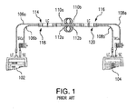
- FIG. 1 illustrates this common practice applied to a duplex fiber system wherein a main test unit 102 is connected to a fiber at a break-out and a remote test unit 104 is connected to the corresponding fiber at a remote end of the cable, and testing is performed by utilization of the two units 102 and 104.
- the exemplary test set up employs two duplex test reference cords (TRCs) 106 and 108.
- First duplex cord 106 consists of two strands of fiber, for example, fibers 106a and 106b.
- Second duplex cord 108 also consists of two strands of fiber, for example, fibers 108a and 108b.
- Each strand of the TRCs 106 and 108 is terminated with a suitable fiber optic connector interface such as SC, ST, LC, or the like.
- the optical fiber link under test comprises a pair of fibers (fibers 110 and 112).
- the first fiber 110 is connected to the main unit 102 via a LC connector 114, while the opposite end 110b of the first fiber 110 is connected to the remote unit 104 via the LC connector 116.
- the second fiber 112 is connected to the main unit 102 via the LC connector 118, while the opposite end 112b of the second fiber 112 is connected to the remote unit 104 via the LC connector 120.
- the network test instrument can measure a total insertion loss of the fiber link under test.
- the light source shown in FIG. 2
- the power meters measure the level of optical power they are receiving through the input ports and compare it to the reference power level in order to calculate the total amount of light loss.
- FIG. 2 is a block diagram of the main unit 102 of the network test instrument, in accordance with an illustrative embodiment of the present invention.
- this main unit 102 will be referred to as a "network test instrument” hereafter.
- the network test instrument 102 may comprise at least one optical source 204.
- the lasers that can be utilized as optical sources 204 in various embodiments of the present invention include, but are not limited to, light emitting diodes (LEDs), fiber lasers, frequency doubled fiber lasers, diode lasers, frequency doubled diode lasers or combinations thereof.
- optical source 204 is a diode laser capable of continuous wave (CW) or modulated transmission, which may be terminated at the output port 206 of the network test instrument 102.
- the input port 208 of the network test instrument 102 is used for the power meter portion of the test instrument and may contain or be connected to an optical power meter 210.
- the power meter 210 converts the transmitted light to electrical energy which is supplied to and then amplified by the operational amplifier (not shown in FIG. 2 ), whose gain can be varied to detect a wide range of optical power levels.
- the output port 206 of the network test instrument 102 may be connected to the input port 208 of the network test instrument 102 by one of the test reference cords, such as, for example, but not limited to, one of the strands of the TRCs 106 and 108 (shown in FIG.1 ). It is noted that during testing the light transmitted by the optical source 212 travels from the output port 206 to the input port 208.
- a heater 202 may be operatively connected to the optical source 204 for heating and maintaining the optical source 204 at a substantially constant temperature.
- one or more temperature sensors 226 may be in contact with the optical source 204 or in close proximity to the optical source 204. The temperature sensor 226 may provide an output signal representing the temperature of the optical source 204 to a temperature compensation circuit 224.
- the temperature compensation circuit 224 may be provided in the network test instrument 102 to control the output of the heater 202 as a function of output power of the optical source 204.
- the power meter 210 periodically monitors the power of the optical source 204 and supplies measurements to a tracking error adjustment program 230 (described below).
- the tracking error adjustment program 230 preferably generates a temperature correcting value based on the measured optical output power.
- the tracking error adjustment program 230 preferably adjusts the temperature of the optical source 204, via the temperature compensation circuit 224 and the heater 202 to obtain an operating temperature for the optical source 204 in which the optical source 204 produces substantially constant output power.
- a heat sink (not shown in FIG.
- the term "heat sink” refers to any component or assembly that takes heat away from the optical source 204.
- One or more microprocessor(s) (CPU) 220 may comprise hardware elements or hardware logic adapted to execute the software programs and manipulate the data structures.
- the one or more microprocessor(s) 220 may execute, for example, the tracking error adjustment program 230.
- the tracking error adjustment program 230 may comprise program instructions stored on one or more computer-readable storage devices, which may include internal memory 228 and/or internal storage 222 of the network test instrument 102.
- the tracking error adjustment program 230 may be, for example, a computer program or program component for controlling temperature adjustment of the optical source 204 based on the determined thermal correction factors. Data gathered, generated, and maintained for use by the tracking error adjustment program 230 may be kept in the internal storage 222 of the main network test instrument 102.
- a power block 216 may provide the power source to operate the network test instrument 102, suitably battery power for portably hand-held use.
- I/O 212 may provide one or more interfaces with the user of the network test instrument 102, and may include a display 214 and input devices 218, such as cursor control keys and other keys for allowing user operation and display/output of results.
- FIG. 3 is a plot diagram showing the relation between tracking error values and temperature.
- tracking error refers to a parameter that defines how the output power of an optical source varies with temperature. Tracking error is a measure of the maximum deviation of this relationship from linearity. These deviations are primarily due to mismatches in the thermal coefficients of expansion for the materials that make up the optical components of the network test instrument 102. Tracking error varies from device to device and the manufacturers of the optical network test instruments typically define acceptable limits or range (e.g., approximately ⁇ 0.2dBs per 10°C). Thus, the variation is a function of temperature, but the variation is not consistent between devices.
- plots 302 and 304 illustrate tracking error values versus temperature for two distinct network test instruments.
- tracking error is not constant and may even reverse direction in some instruments. Since there are several complicated factors in determining the cause of tracking error and since tracking error is not constant, it cannot be easily compensated for like other temperature-dependent parameters. Accordingly, a preferred embodiment of the present invention contemplates the use of a software program, such as tracking error adjustment program 230, during operation of the network test instrument 102 to cancel the effects of tracking error.
- FIG. 4 is a flowchart of operational steps of the tracking error adjustment program 230 of FIG. 2 , in accordance with an illustrative embodiment of the present invention.
- the tracking error adjustment program 230 may be, for example, a computer program or program component for improving stability of an optical source 202 of the network test instrument 102 by cancelling the effects of tracking error.
- the steps described below comprise a self-contained calibration process of the network test instrument 102.
- the output 206 is connected to the input port 208 by an external patch cord, as described above in connection with FIG. 2 .
- the tracking error adjustment program 230 preferably performs a temperature sweep test of the optical source 204.
- the heater 202 operatively coupled to the optical source 204, performs the temperature sweep test under control of the tracking error adjustment program 230.
- the tracking error over the entire desired operating temperature range can be characterized as a characteristic curve.
- This characteristic curve can be sampled at predetermined sampling points. The number of sampling points can be selected arbitrarily, e.g. as many as needed.
- all heating power is focused directly to the optical source structure 204. Sampling can thus be done with a fast temperature sweep over the whole desired temperature range.
- the obtained sampling points can be stored in the storage component 222 of the network test instrument 102.
- the tracking error adjustment program 230 preferably continuously measures optical power output of the optical source 204 during the calibration of the network test instrument 102.
- this step preferably involves obtaining periodic measurement data from one or more power meters 210 operatively coupled to the optical source 204 via output 206 and input 208 ports, respectively, as shown in FIG. 2 .
- the tracking error adjustment program 230 preferably determines whether the measured optical output power of the optical source 204 is within acceptable limits. Preferably, the measured optical output power gain/loss should not exceed 0.05 dBs, irrespective of ambient temperature. In response to determining that the measured optical output power of the optical source 204 is within the acceptable range (step 406, yes branch), the tracking error adjustment program 230 may take next measurements after a predetermined period of time (step 404). In other words, if the tracking adjustment program 230 determines that the optical source produces acceptable output it may not be necessary to compensate for tracking error changes.
- the tracking error adjustment program 230 in response to determining that the measured optical output power of the optical source 204 is outside acceptable range (step 406, no branch), the tracking error adjustment program 230 preferably generates a temperature correcting value, at step 408.
- the temperature correcting value comprises tracking error value.
- a curve describing the tracking error values as a function of temperature can be established.
- the tracking error adjustment program 230 preferably represents the tracking error values as (x, y) pairs, where x represents temperature and y represents tracking error adjustment value. In other words, there are discrete data points over the operating temperature range that describe tracking error as a function of temperature.
- the tracking error adjustment program 230 at step 408, preferably estimates the temperature correcting values (tracking error values) using a polynomial curve fit, as described above.
- the tracking error adjustment program 230 optionally stores the calculated temperature correcting values and/or obtained optical power measurements, for example, in the storage 222 of the network test instrument 102.
- the tracking error adjustment program 230 loads this data in the form of a table with values computed at step 408 associated with a given temperature or with polynomial coefficients. Each entry in such table may indicate the values to be used for the corresponding temperature. Each line entry in the table may represent an incremental change in temperature.
- the temperature step per table entry can be as large or as small as desired and is only limited by the available memory in the storage 222 of the network test instrument 102.
- the tracking error adjustment program 230 preferably adjusts the temperature of the optical source 204 based, for example, on the temperature correcting values determined at step 408.
- the tracking error adjustment program 230 is preferably configured to communicate with a compensation circuit 224.
- the compensation circuit 224 is preferably provided to control the temperature of the heater 202.
- the compensation circuit 210 may suitably adjust the output (power) of the optical source 204 based on the temperature correcting values provided by the tracking error adjustment program 230 in order to maintain a substantially constant optical output power of the optical source 204.
- the various embodiments of the present invention provide a cost effective method for improving stability of an optical source in a self-contained environment of an optical network test instrument.
- various components of the network test instrument learn how the optical source behaves in its specified operating environment and adapt the control accordingly to maintain stable and accurate operating characteristics over the specified operating conditions.
- aspects of the present invention may be embodied as a system, method or computer program product. Accordingly, aspects of the present invention may take the form of an entirely hardware embodiment, an entirely software embodiment (including firmware, resident software, micro-code, etc.) or an embodiment combining software and hardware aspects that may all generally be referred to herein as a "circuit,” “module” or “system.” Furthermore, aspects of the present invention may take the form of a computer program product embodied in one or more computer readable medium(s) having computer readable program code embodied thereon.
- the computer readable medium may be a computer readable signal medium or a computer readable storage medium.
- a computer readable storage medium may be, for example, but not limited to, an electronic, magnetic, optical, electromagnetic, infrared, or semiconductor system, apparatus, or device, or any suitable combination of the foregoing.
- a computer readable storage medium may be any tangible medium that can contain, or store a program for use by or in connection with an instruction execution system, apparatus, or device.
- a computer readable signal medium may include a propagated data signal with computer readable program code embodied therein, for example, in baseband or as part of a carrier wave. Such a propagated signal may take any of a variety of forms, including, but not limited to, electro-magnetic, optical, or any suitable combination thereof.
- a computer readable signal medium may be any computer readable medium that is not a computer readable storage medium and that can communicate, propagate, or transport a program for use by or in connection with an instruction execution system, apparatus, or device.
- Program code embodied on a computer readable medium may be transmitted using any appropriate medium, including but not limited to wireless, wireline, optical fiber cable, RF, etc., or any suitable combination of the foregoing.
- Computer program code for carrying out operations for aspects of the present invention may be written in any combination of one or more programming languages, including an object oriented programming language such as Java, Smalltalk, C++ or the like and conventional procedural programming languages, such as the "C" programming language or similar programming languages.
- object oriented programming language such as Java, Smalltalk, C++ or the like
- conventional procedural programming languages such as the "C" programming language or similar programming languages.
- These computer program instructions may also be stored in a computer readable medium that can direct a computer, other programmable data processing apparatus, or other devices to function in a particular manner, such that the instructions stored in the computer readable medium produce an article of manufacture including instructions which implement the function/act specified in the flowchart and/or block diagram block or blocks.
- the computer program instructions may also be loaded onto a computer, other programmable data processing apparatus, or other devices to cause a series of operational steps to be performed on the computer, other programmable apparatus or other devices to produce a computer implemented process such that the instructions which execute on the computer or other programmable apparatus provide processes for implementing the functions/acts specified in the flowchart and/or block diagram block or blocks.
- each block in the flowchart or block diagrams may represent a module, segment, or portion of code, which comprises one or more executable instructions for implementing the specified logical function(s).
- the functions noted in the block may occur out of the order noted in the figures. For example, two blocks shown in succession may, in fact, be executed substantially concurrently, or the blocks may sometimes be executed in the reverse order, depending upon the functionality involved.
Landscapes
- Physics & Mathematics (AREA)
- General Physics & Mathematics (AREA)
- Condensed Matter Physics & Semiconductors (AREA)
- Electromagnetism (AREA)
- Optics & Photonics (AREA)
- Optical Communication System (AREA)
- Semiconductor Lasers (AREA)
- Measuring Temperature Or Quantity Of Heat (AREA)
Applications Claiming Priority (1)
| Application Number | Priority Date | Filing Date | Title |
|---|---|---|---|
| US14/145,443 US9414448B2 (en) | 2013-12-31 | 2013-12-31 | Stability of an optical source in an optical network test instrument |
Publications (2)
| Publication Number | Publication Date |
|---|---|
| EP2889968A2 true EP2889968A2 (de) | 2015-07-01 |
| EP2889968A3 EP2889968A3 (de) | 2015-10-21 |
Family
ID=52272836
Family Applications (1)
| Application Number | Title | Priority Date | Filing Date |
|---|---|---|---|
| EP14197811.4A Withdrawn EP2889968A3 (de) | 2013-12-31 | 2014-12-12 | Verbesserung der Stabilität einer optischen Quelle in einem optischen Netzwerktestinstrument |
Country Status (6)
| Country | Link |
|---|---|
| US (1) | US9414448B2 (de) |
| EP (1) | EP2889968A3 (de) |
| JP (1) | JP2015130500A (de) |
| CN (1) | CN104753589B (de) |
| AU (1) | AU2014277665B2 (de) |
| CA (1) | CA2875867A1 (de) |
Families Citing this family (5)
| Publication number | Priority date | Publication date | Assignee | Title |
|---|---|---|---|---|
| JP6565498B2 (ja) * | 2015-08-31 | 2019-08-28 | ウシオ電機株式会社 | 光源装置及び制御装置 |
| US10128943B2 (en) * | 2017-04-06 | 2018-11-13 | At&T Intellectual Property I, L.P. | Predictive maintenance of optical transport network system |
| CN116683987B (zh) * | 2023-08-04 | 2023-10-13 | 镭神技术(深圳)有限公司 | 调制光芯片通道测试方法、装置和系统 |
| CN119147228B (zh) * | 2024-11-12 | 2025-02-11 | 青岛华航环境科技有限责任公司 | 一种智能磁光开关测试系统及方法 |
| CN119269042B (zh) * | 2024-12-09 | 2025-05-06 | 广东欧谱曼迪科技股份有限公司 | 一种光纤检测方法、装置、电子设备及存储介质 |
Citations (2)
| Publication number | Priority date | Publication date | Assignee | Title |
|---|---|---|---|---|
| US20060062116A1 (en) * | 2004-09-07 | 2006-03-23 | Hiroto Ishibashi | Optical data link capable of compensating tracking error |
| US20090274471A1 (en) * | 2008-04-30 | 2009-11-05 | General Instrument Corporation | Method and apparatus for controlling the optical output power from a burst mode laser |
Family Cites Families (9)
| Publication number | Priority date | Publication date | Assignee | Title |
|---|---|---|---|---|
| US7433375B2 (en) * | 2003-10-09 | 2008-10-07 | National Semiconductor Corporation | Laser trim and compensation methodology for passively aligning optical transmitter |
| US7321606B2 (en) | 2003-10-09 | 2008-01-22 | National Semiconductor Corporation | Laser trim and compensation methodology for passively aligning optical transmitter |
| JP2010004639A (ja) | 2008-06-19 | 2010-01-07 | Yazaki Corp | ワイヤーハーネス外装用の硬質チューブ |
| JP2010040639A (ja) * | 2008-08-01 | 2010-02-18 | Sumitomo Electric Device Innovations Inc | 光半導体装置の試験方法および光半導体装置の試験装置 |
| JP5180250B2 (ja) * | 2010-03-18 | 2013-04-10 | 株式会社Qdレーザ | レーザシステム |
| JP5749458B2 (ja) | 2010-07-21 | 2015-07-15 | 富士通オプティカルコンポーネンツ株式会社 | 光送信モジュール、および、光送信モジュールの制御方法 |
| CN102970080A (zh) * | 2012-10-31 | 2013-03-13 | 青岛海信宽带多媒体技术有限公司 | 光模块及其激光器工作温度的调节方法 |
| US9485016B2 (en) * | 2013-09-20 | 2016-11-01 | Fluke Corporation | Hands-free optical fiber testing using optical loss test instrument |
| US9572218B2 (en) * | 2013-11-19 | 2017-02-14 | Usl Technologies, Llc | High-stability light source system and method |
-
2013
- 2013-12-31 US US14/145,443 patent/US9414448B2/en active Active
-
2014
- 2014-12-12 EP EP14197811.4A patent/EP2889968A3/de not_active Withdrawn
- 2014-12-15 AU AU2014277665A patent/AU2014277665B2/en not_active Ceased
- 2014-12-22 JP JP2014258565A patent/JP2015130500A/ja active Pending
- 2014-12-22 CA CA2875867A patent/CA2875867A1/en not_active Abandoned
- 2014-12-30 CN CN201410840225.8A patent/CN104753589B/zh not_active Expired - Fee Related
Patent Citations (2)
| Publication number | Priority date | Publication date | Assignee | Title |
|---|---|---|---|---|
| US20060062116A1 (en) * | 2004-09-07 | 2006-03-23 | Hiroto Ishibashi | Optical data link capable of compensating tracking error |
| US20090274471A1 (en) * | 2008-04-30 | 2009-11-05 | General Instrument Corporation | Method and apparatus for controlling the optical output power from a burst mode laser |
Also Published As
| Publication number | Publication date |
|---|---|
| CN104753589B (zh) | 2019-07-12 |
| CA2875867A1 (en) | 2015-06-30 |
| CN104753589A (zh) | 2015-07-01 |
| EP2889968A3 (de) | 2015-10-21 |
| US9414448B2 (en) | 2016-08-09 |
| AU2014277665A1 (en) | 2015-07-16 |
| AU2014277665B2 (en) | 2018-07-19 |
| JP2015130500A (ja) | 2015-07-16 |
| US20150189709A1 (en) | 2015-07-02 |
Similar Documents
| Publication | Publication Date | Title |
|---|---|---|
| AU2014277665B2 (en) | Improving stability of an optical source in an optical network test instrument | |
| US9046425B2 (en) | Opticalfiber temperature distribution measurement apparatus | |
| EP2854307B1 (de) | Benutzerinteraktionsreduziertes Glasfasertesten unter Verwendung eines optischen Verlusttestinstruments | |
| CN107408982A (zh) | 用于otdr发送器噪声补偿的装置和方法 | |
| US9008588B2 (en) | System and method for the calibration and verification of wireless networks with control network | |
| CN103299154A (zh) | 对用于校正介质对光信号的作用的设备进行配置的方法和系统、用于校正该作用的方法、设备和系统 | |
| CN112204369A (zh) | 用于测量光纤的传输损耗的方法以及otdr测量装置 | |
| US20180183526A1 (en) | Calibration of pluggable optical module | |
| WO2017220006A1 (zh) | 光模块出光功率定标的方法及装置 | |
| US8525981B2 (en) | Return loss measurement system | |
| US7954358B2 (en) | Laser driver bias current calibration | |
| WO2017103639A1 (en) | Method of qualifying wide-band multimode fiber from single wavelength characterization using emb extrapolation, corresponding system and computer program. | |
| US10826616B2 (en) | Reconfigurable digital predistortion circuit | |
| US20200072681A1 (en) | Temperature measurement apparatus, temperature measurement method, and storage medium | |
| US9722700B2 (en) | Wavelength division multiplexing system and method including wavelength monitoring | |
| CN103092815B (zh) | 对监测装置中的传递函数进行校准的方法 | |
| Birand et al. | Measurements-based power control-a cross-layered framework | |
| TWI381183B (zh) | 判斷交流/直流交叉校正係數之系統和方法 | |
| JP6693219B2 (ja) | 非線形特性推定装置及び非線形特性推定方法 | |
| CN111416664A (zh) | 一种色散补偿方法、装置和存储介质 | |
| US7991031B2 (en) | Injection seeded laser ratio loop control | |
| US20160197672A1 (en) | Method of measuring optical return loss | |
| US10250010B1 (en) | Control of VCSEL-based optical communications system | |
| CN116131940B (zh) | 光不连续性测试仪校准装置、系统及方法 | |
| CN104132752B (zh) | 一种温度测量精度控制装置及方法 |
Legal Events
| Date | Code | Title | Description |
|---|---|---|---|
| PUAI | Public reference made under article 153(3) epc to a published international application that has entered the european phase |
Free format text: ORIGINAL CODE: 0009012 |
|
| 17P | Request for examination filed |
Effective date: 20141212 |
|
| AK | Designated contracting states |
Kind code of ref document: A2 Designated state(s): AL AT BE BG CH CY CZ DE DK EE ES FI FR GB GR HR HU IE IS IT LI LT LU LV MC MK MT NL NO PL PT RO RS SE SI SK SM TR |
|
| AX | Request for extension of the european patent |
Extension state: BA ME |
|
| PUAL | Search report despatched |
Free format text: ORIGINAL CODE: 0009013 |
|
| AK | Designated contracting states |
Kind code of ref document: A3 Designated state(s): AL AT BE BG CH CY CZ DE DK EE ES FI FR GB GR HR HU IE IS IT LI LT LU LV MC MK MT NL NO PL PT RO RS SE SI SK SM TR |
|
| AX | Request for extension of the european patent |
Extension state: BA ME |
|
| RIC1 | Information provided on ipc code assigned before grant |
Ipc: H01S 5/024 20060101AFI20150914BHEP Ipc: H01S 5/0683 20060101ALI20150914BHEP Ipc: H01S 5/06 20060101ALI20150914BHEP |
|
| 17Q | First examination report despatched |
Effective date: 20181218 |
|
| STAA | Information on the status of an ep patent application or granted ep patent |
Free format text: STATUS: THE APPLICATION IS DEEMED TO BE WITHDRAWN |
|
| 18D | Application deemed to be withdrawn |
Effective date: 20190430 |