EP2889775B1 - Rechner mit selbstüberwachungsfunktion und überwachungsprogramm - Google Patents
Rechner mit selbstüberwachungsfunktion und überwachungsprogramm Download PDFInfo
- Publication number
- EP2889775B1 EP2889775B1 EP13830967.9A EP13830967A EP2889775B1 EP 2889775 B1 EP2889775 B1 EP 2889775B1 EP 13830967 A EP13830967 A EP 13830967A EP 2889775 B1 EP2889775 B1 EP 2889775B1
- Authority
- EP
- European Patent Office
- Prior art keywords
- observer
- program
- test
- monitoring
- input
- Prior art date
- Legal status (The legal status is an assumption and is not a legal conclusion. Google has not performed a legal analysis and makes no representation as to the accuracy of the status listed.)
- Active
Links
Images



Classifications
-
- G—PHYSICS
- G06—COMPUTING OR CALCULATING; COUNTING
- G06F—ELECTRIC DIGITAL DATA PROCESSING
- G06F11/00—Error detection; Error correction; Monitoring
- G06F11/36—Prevention of errors by analysis, debugging or testing of software
- G06F11/3668—Testing of software
- G06F11/3672—Test management
- G06F11/3688—Test management for test execution, e.g. scheduling of test suites
-
- G—PHYSICS
- G06—COMPUTING OR CALCULATING; COUNTING
- G06F—ELECTRIC DIGITAL DATA PROCESSING
- G06F11/00—Error detection; Error correction; Monitoring
- G06F11/36—Prevention of errors by analysis, debugging or testing of software
- G06F11/3668—Testing of software
- G06F11/3672—Test management
-
- G—PHYSICS
- G06—COMPUTING OR CALCULATING; COUNTING
- G06F—ELECTRIC DIGITAL DATA PROCESSING
- G06F11/00—Error detection; Error correction; Monitoring
- G06F11/36—Prevention of errors by analysis, debugging or testing of software
- G06F11/3668—Testing of software
- G06F11/3672—Test management
- G06F11/3692—Test management for test results analysis
Definitions
- the present disclosure relates to a computer having a self-monitoring function and a monitoring program.
- ECU electric control unit
- the control computer in such an embedded system is widely used in fields other than the automobile such as a plant, a production line, or the like.
- a self-diagnosis function is often provided in order to prevent an accident caused by the breakdown or failure.
- the self-diagnosis function is called “Diagnosis” or “OBD (On-board diagnostics)” (see “ ODB-II On-Board Diagnostics", [online], B&B Electronics, retrieved on July 23, 2012 from the Internet at http://www.obdii.com/ ).
- ODB-II On-Board Diagnostics [online], B&B Electronics, retrieved on July 23, 2012 from the Internet at http://www.obdii.com/ ).
- the self-diagnosis function is capable of detecting an abnormal state such as the occurrence of an undefined signal or the like in the computer, and issuing an alarm to a user, stopping the system, and recording log information.
- US 5 724 504 A discloses the evaluation of given test cases with respect to a coverage criteria on the behavioural simulator for the software under test.
- US 2010/192128 A1 discloses the automatic code generation for both the software under test and test cases starting from a model, as well as comparing coverage metrics of versions of the code with and without instrumented test point, by using software probes within the code.
- US 8 140 986 B2 discloses generating test scenarios using reusable triggers indicating graphical user interface (GUI) elements and actions.
- GUI graphical user interface
- the computer having the self-diagnosis function described above is capable of detecting an abnormal operation caused by the breakdown of the circuit or the failure of the program and issuing an alarm to the user.
- the self-diagnosis function is capable of detecting that the system is brought into the abnormal state, but is not capable of detecting that the system is in what is called "an unchecked state” that is the state of the system before the abnormal operation of the system occurs.
- a test scenario is usually generated by assuming operations performed by the user.
- an unassumed operation is often performed.
- software has to handle an unchecked scenario so that it is not possible to guarantee that processing is performed normally. That is, there is a possibility that a failure occurs in the scenario, and the system becomes unstable or the abnormal operation is caused.
- Such an unchecked state is not a critical state, but an operational risk of the software is present in the state, and hence it is desirable to positively detect the state and provide a notification.
- the disclosure has been achieved in view of the above problem, and an object thereof is to provide a computer having a self-monitoring function and a monitoring program capable of detecting that a user has performed an operation that does not exist in a test scenario.
- a first teaching of the present disclosure is a computer having a self-monitoring function.
- the computer includes an input unit configured to acquire an input operation, a first program execution unit configured to execute a computing program performing a computation based on the input operation acquired by the input unit, a test scenario storage unit configured to store a plurality of test scenarios for the computing program, and a second program execution unit configured to execute a monitoring program determining whether or not the input operation acquired by the input unit corresponds to any of the plurality of the stored test scenarios.
- the computing program is a program serving as a monitoring target, and is a program that performs the computation based on the input operation acquired via the input unit provided in the computer.
- the input unit is a human interface device such as a mouse, a touch panel, or a keyboard, and the input operation denotes information inputted from a user through the device.
- the input operation may be an event directly related to hardware such as a click, a tap, or a key press, or may also be a value inputted via a GUI (Graphical User Interface) component such as a text box, a drop-down list, or a slider.
- GUI Graphic User Interface
- the monitoring program is a program that acquires the input operation by a user and determines whether or not the input operation is already checked. The determination of whether or not the input operation is already checked is performed by comparing the acquired input operation with the plurality of the stored test scenarios.
- the test scenario is data in which the operation related to the test of the computing program is recorded, and the monitoring program can determine whether or not the input operation is already checked by confirming whether or not the acquired input operation matches the detail of the operation recorded in the test scenario.
- Each of the test scenarios may include details and an order of a plurality of the input operations
- the monitoring program may acquire a plurality of the input operations from the input unit and, in a case where the plurality of the acquired input operations match the details and the order of the input operations included in any of the test scenarios, the monitoring program may determine that the acquired input operation corresponds to the test scenario.
- the checking target may be a plurality of the input operations. That is, it is possible to determine whether or not the inputted operation corresponds to the test scenario by comparing the operations inputted successively from the input unit with the operations chronologically recorded in the test scenario and checking whether or not the contents and the order of the inputted operations match those of the recorded operations.
- the monitoring program may notify the computing program or an external program that a system is in an unchecked state in a case where the acquired input operation does not correspond to any of the plurality of the stored test scenarios.
- the monitoring program notifies the computing program or the external program of the situation in which the operation is not checked. With this, it is possible to perform processing coping with an abnormality occurrence such as output to a system log, notification to an external system, or transition to a safe mode, and assure the safety of the system.
- a second aspect of the present invention is a monitoring program that monitors any program.
- the monitoring program according to the second aspect of the present disclosure is a monitoring program executed simultaneously with a computing program performing a computation and monitoring an input operation to the computing program including an input acquisition step of acquiring the input operation to the computing program, and an input determination step of determining whether or not the acquired input operation corresponds to any of a plurality of pre-stored test scenarios for the computing program.
- each of the stored test scenarios may include details and an order of a plurality of the input operations
- the input acquisition step may include acquiring a plurality of the input operations, and in a case where the plurality of the acquired input operations match the details and the order of the input operations included in any of the test scenarios, the input determination step may include determining that the acquired input operation corresponds to the test scenario.
- a step of notifying the computing program or an external program that a system is in an unchecked state may be executed.
- the present disclosure can be defined as the monitoring program that monitors the input operation to any program.
- a third teaching of the present disclosure is a software generation device that generates a computing program that performs a computation and a monitoring program that monitors an input operation to the computing program.
- the software generation device includes a computing program input unit configured to receive an input of a code of the computing program, a test scenario input unit configured to receive an input of a plurality of test scenarios for the computing program that are described in a modeling language, a computing program generation unit configured to generate the computing program, a monitoring program generation unit configured to generate the monitoring program including the plurality of the test scenarios and determining whether or not the input operation to the computing program corresponds to any of the plurality of the test scenarios, and a program writing unit configured to record the computing program and the monitoring program in an object computer, and the computing program generation unit adds processing for notifying the monitoring program of the input operation performed to the computing program, with predetermined processing being performed by the computing program used as a trigger on the computing program.
- each of the test scenarios may include details and an order of a plurality of the input operations
- the monitoring program may acquire a plurality of the input operations and, in a case where the plurality of the acquired input operations match the details and the order of the input operations included in any of the test scenarios, the monitoring program may determine that the acquired input operation corresponds to the test scenario.
- the monitoring program may be capable of notifying the computing program or an external program that a system is in an unchecked state in a case where the acquired input operation does not correspond to any of the plurality of the test scenarios.
- the present disclosure can be defined as the software generation device that records the computing program and the monitoring program in the computer according to the first teaching of the present disclosure. Note that the above processing and units can be combined arbitrarily and implemented as long as no technical conflicts occur.
- the computer having the self-monitoring function and the monitoring program capable of detecting that the user has performed the operation that does not exist in the test scenario.
- FIG. 1 is a view for explaining a method for generating the computing program and the monitoring program according to the present invention.
- a Java (registered trademark) application is generated by using Eclipse as an open-source integrated development environment will be described.
- the software requirement is a defined requirement to be satisfied by the software.
- the software requirement may be described in natural language or may also be described in a language such as a specification and description language that can be interpreted by a computer directly.
- a software developer designs a program from the defined software requirement, and performs generation of an application code (the reference numeral 15) as the source code for the computing program.
- an application code the reference numeral 15
- the description of the program design is omitted but, for example, a software model may be generated from the software requirement and the code may be generated, or the program design may be generated from the software requirement and coding may be performed manually.
- Existing techniques and methods can be used for the generation of the application code 15.
- test scenario (the reference numeral 11) from the software requirement.
- the test scenario is a scenario described in natural language that is used for testing the program.
- a series of operations by a user and results of the operations are described, and the developer performs the test of the application code 15 while referring to the scenario.
- the test scenario can also be described in UML (United Modeling Language).
- UML United Modeling Language
- a sequence diagram the reference numeral 12
- a state chart the reference numeral 13
- FIG. 1 shows an example in which the test scenario (the reference numeral 11) described in natural language, the test scenario (the reference numeral 12) by the sequence diagram, and the test scenario (the reference numeral 13) by the state chart are generated in the order shown, but it is only necessary to generate any of the test scenarios, and it is not necessary to generate all of the test scenarios.
- An observer code (the reference numeral 14) is a code generated based on the test scenario, and is the source code for the monitoring program that monitors whether or not the computing program operates according to the test scenario.
- IBM's Rational Rhapsody registered trademark
- the observer code may also be manually generated by referring to the test scenario (the reference numeral 11) described in natural language or the test scenario (the reference numeral 12) by the sequence diagram.
- the observer code 14 is generated for each test scenario described above.
- the observer code 14 and the application code 15 are independent of each other, and hence, even when the monitoring program is generated from the observer code, the monitoring program cannot monitor an input operation performed to the computing program without any alteration.
- a build is performed after both of the programs are made capable of exchanging information by utilizing aspect-oriented programming. The detail of the aspect-oriented programming will be described later.
- an actual product is completed.
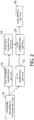
- FIG. 2 is a view showing the system configuration of the software generation device according to the present invention.
- a software requirement storage section 21 is a unit that stores the software requirement (the reference numeral 10) in which the requirement to be satisfied by the software is described.
- the software requirement may be described in natural language or may also be described in the specification and description language for describing the specifications of the software such as LTL (Linear Temporal Logic) or CTL (Computational Tree Logic).
- a test scenario generation section 22 is a unit that generates the test scenario based on the software requirement. As described above, the test scenario may be described in natural language or may also be described using the sequence diagram or the state chart. In the case where the test scenario is described in UML, it is possible to use various UML plug-ins provided for Eclipse. The software developer generates the test scenario using an editor provided by the test scenario generation section 22.
- a code generation section 23 is a unit that generates the application code 15.
- the code may be generated by manual coding using the editor, or a software model is generated and the code may also be automatically generated from the software model. It is possible to use various design tools provided for Eclipse also in the generation of the software model and the generation of the application code. For example, when the development tool such as MathWork's Simulink (registered trademark) is used, it is possible to automatically generate the application code from the software model.
- MathWork's Simulink registered trademark
- An observer generation section 24 is a unit that generates the observer code from the test scenario generated in the test scenario generation section 22. As described above, since one observer code corresponds to one test scenario, in the case where a plurality of the test scenarios are present, a plurality of the observer codes are generated by the observer generation section 24.
- the state chart is generated in the test scenario generation section 23, it is possible to automatically generate the Java observer code by Rational Rhapsody described above .
- the observer code may also be manually generated from the test scenario (the reference numeral 11) in natural language or the test scenario (the reference numeral 12) by the sequence diagram.
- a code combination section 25 is a unit that combines and builds the observer code generated by the observer generation section 24 and the application code generated by the code generation section 23.
- the observer code and the application code are independent of each other, they cannot refer to each other mutually without any alteration, and cannot monitor the input operation performed to the computing program. To cope with this, in the present embodiment, transfer of the input operation between the codes is realized by using the aspect-oriented programming.
- the aspect-oriented programming is a technique for incorporating a concept that cannot be classified using the object into the program.
- a function difficult to classify that is additional processing different from original functional processing such as, e.g., logging, assertion, or error processing in the program.
- This processing is called an aspect, and an execution point at which the aspect is incorporated is called a joint point. That is, by setting processing for transferring the input operation to the observer code as the aspect and disposing the joint point in the observer code and the application code, it is possible to transfer the input operation by the user.
- the software developer can add the function without altering the generated code only by generating the aspect and specifying the joint point.
- AspectJ is a representative example of an aspect-oriented language.
- AspectJ is a language in which specifications for realizing the aspect-oriented programming are added to Java language.
- the code combination section 25 couples the application code and the observer code using AspectJ. Specifically, the code of transferring the input operation is generated as the aspect, and the joint point is defined at a part to which the input operation is transferred in each of the application code and the observer code. With this, it becomes possible for the monitoring program to acquire the input operation to the computing program.
- the combination of the code is performed by using an AspectJ plug-in provided for Eclipse.
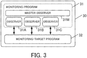
- FIG. 3 is a view showing the configuration of the program generated by the software generation device according to the first embodiment.
- the computing program generated from the application code is referred to as a monitoring-target program
- the monitoring program generated from the observer code is referred to as an observer.
- the application code and the observer code are built by the code combination section 25 and an executable program 30 is generated.
- the executable program 30 includes a monitoring-target program 32 as a program corresponding to the application code, and a plurality of observers 31A, 31B, 31C ... as programs corresponding to the individual observer codes.
- the input operation performed to the monitoring-target program is inputted to each observer substantially simultaneously.
- the monitoring-target program and each observer may be stored in one module or may also be stored in a plurality of modules separately as long as a condition that the monitoring-target program and each observer are executed simultaneously is satisfied.
- a master observer 31M is a program for checking the states of the plurality of the observers.
- the master observer 31M is stored in the observer generation section 24 as a common program that does not depend on the application, and is built simultaneously in the code combination section 25.
- the area of the reference numeral 31 shown in FIG. 3 is the monitoring program in the present invention. The operation of the master observer will be described later.
- the generated executable program 30 is written in a storage device (ROM) of a computer that operates in actual environment in a code writing section 26.
- the computer that operates in actual environment is, e.g. , an on-board computer (ECU) mounted on an automobile or the like.
- FIG. 4 is a flow chart showing software development procedures according to the first embodiment.
- the software developer generates the application code from the software requirement in the code generation section 23 (S11), and designs the test scenario from the software requirement in the test scenario generation section 22 (S12) .
- One of the procedure in Step S11 and the procedure in Step S12 may be performed before the other thereof, or both of the procedures may be performed concurrently.
- the software developer generates the observer code from the test scenario in the observer generation section 24 (S13), and then builds both of the application code and the observer code in the code combination section 25 (S14). With this, the executable program 30 is obtained. Lastly, the software developer writes the generated executable program 30 in a target computer in the code writing section 26 (S15), and the software development is completed.
- FIG. 5 is a system configuration diagram of an on-board terminal 100 in which the executable program 30 is executed.
- the on-board terminal 100 has a processor 101 and a storage device 102.
- the executable program 30 is stored in the storage device 102, and is executed in the processor 101.
- the user can perform an input to the monitoring-target program 32 through an input device 103.
- the input device 103 is a touch panel in the present embodiment, but may also be a keyboard or a pointing device.
- the on-board terminal 100 has a communication device 104 for performing radio communication with the outside and a disk device 105 for recording information.
- FIG. 6 shows an example of the test scenario of each observer.
- FIG. 7 is a view showing the state transition of the monitoring program by the operation of the user. For example, after transition from Main Menu to Sub-menu 1, the operations can be performed in the order of Operation A, Operation B, Operation C, and Operation D.
- the test scenario corresponding to this series of operations is Test Scenarios 1 and 2.
- the order of the operations when the test of the program is performed is recorded, and each of the observers (31A, 31B, 31C ...) stores one test scenario.
- six observers are used to monitor all of the test scenarios shown in FIG. 6 .
- the operation is the operation of which the operation confirmation is made at the stage of the program test. Conversely, in the case where the operation that does not match any of the test scenarios is performed, it is possible to determine that the current state is a state where the operation confirmation is not made, i.e., an unchecked state.
- a method for determining which test scenario the input operation currently performed by the user matches will be described by using a term activity/inactivity of the observer.
- the observer is in an active state means a situation in which the input operation performed by the user matches the test scenario of the observer.
- the observer is in an inactive state means a situation in which the operation performed by the user does not match the test scenario of the observer.
- Each observer can switch the state thereof (the active state/the inactive state) in accordance with the result of the comparison between the acquired input operation and test scenario stored in the observer.
- the test scenario starts from a screen serving as a starting point.
- a main menu screen is the starting point of all of the test scenarios. That is, the state where the monitoring-target program displays the main menu is the state corresponding to all of the test scenarios, and all of the observers are brought into the active state.
- the operation performed by the user is inputted to the monitoring-target program first.
- the joint point is defined together with a function for acquiring the input operation in the code of the monitoring-target program, and the aspect is executed every time the user performs the input operation.
- processing for acquiring the input operation and transmitting the input operation to the observer is described. With this, the inputted operation is transmitted to all of the observers.
- the list of the observer in the active state in the case where the following operations are performed from Main Menu in the order shown is as follows. Note that, for the convenience of the description, the observers corresponding to TEST SCENARIOS 1 to 6 shown as examples are referred to as Observers 1 to 6.
- the monitoring program 31 can determine whether or not the monitoring-target program 32 is in a checked state based on the active state of the observer. Monitoring processing performed by the monitoring program 31 that operates on the on-board terminal 100 is shown by a flow chart in FIG. 8 .
- the flow chart in FIG. 8 is started.
- Step S21 every time the user performs the input operation, all of the observers acquire the input operation.
- Step S22 and Step S23 each observer compares the operation acquired in Step S21 with the test scenario of the observer. As the result, in the case where the observer is the activation target, the observer switches its state to the active state (S22) and, in the case where the observer is the inactivation target, the observer switches its state to the inactive state (S23). The observer in the inactive state notifies the master observer 31M that the observer is inactivated.
- Step S24 is Step of detecting that all of the observers are in the inactive state. Specifically, the master observer 31M counts the number of observers in the active state. At this point, in the case where there is no observer in the active state, that means that the operation that does not exist in the test scenario is performed, and hence the processing proceeds to Step S25, and the master observer 31M generates an event called user fail.
- the user fail is an event that provides a notification that the program is brought into the unchecked state. For example, in the case where a system for controlling a vehicle is brought into the user fail state, it is conceivable to change the mode of the system to a safe mode that is a minimal configuration required for driving. In the case where the situation is considered to be relatively sate, a notification may be provided only to a driver.
- the master observer 31M starts an external program for providing notification of an abnormality, and the external program notifies the driver of the occurrence of the abnormality through a display (not shown) such as LED or LCD.
- relevant information is recorded in the disk device 105 as a log.
- the information to be recorded includes logs of memory dump of the program and the operation performed by the user. Note that the log information may be transmitted to a management center 200 through the communication device 104.
- the notification of the occurrence of the abnormality may be provided to the monitoring-target program.
- Step S21 the processing proceeds to Step S21 and waits for the input operation again.
- the observer executed on the computer monitors the input to the monitoring-target program, and it is thereby possible to detect that the input operation having the untested pattern is performed by the user. With this, it is possible to provide a notification before the system becomes critical and increase the safety of the system.
- the master observer generates the user fail in the case where all of the observers are brought into the inactive state, but there may be provided another program for checking the active state of the observer and the program may generate the user fail in the case where all of the observers are brought into the inactive state.
- the operation is ended after the required processing is performed in the case where the user fail is generated, but the monitoring may be continued after recovery processing is performed in the case where the observer is activated again after the user fail is generated.
- the recovery processing may be processing for notifying the outside that the checked state is established again, or may also be processing for changing the mode of the system from the safe mode back to a normal mode.
- the main menu is used as the starting point of each test scenario and the activation of all of the observers is performed when the screen is changed to the main menu, but the timing of the activation of the observers can be set to any timing according to the test scenario. For example, there may be observers activated when the screen is changed to the sub-menu, and there may also be observers activated when an arbitrary condition is satisfied.
- the language to be used may be a language other than Java.
- the language may be, e.g., C language, C++, or PHP and, when the observer can be notified of the input operation to the monitoring-target program by some method, it is not necessary to use the aspect-oriented programming.
- Embedded Tester as the development tool by BTC Embedded Systems AG is used, it is possible to connect the observer and the program generated in C language and execute the monitoring of the program.
- a second embodiment is an embodiment in which the monitoring-target program and the observer operate on pieces of hardware that are independent of each other.
- FIG. 9 is a view showing a circuit structure according to the second embodiment.
- the generation of the program is performed by the software generation device, but the second embodiment is different from the first embodiment in the following points.
- the codes generated in the code generation section 23 and the observer generation section 24 are not in Java but in hardware description language such as AHDL or VHDL.
- the combination of the code in the code combination section 25 is not performed, and the monitoring-target program and the observer are built separately.
- the code writing section 26 the monitoring-target program and the observer are written in digital circuits such as integrated circuits or the like separately.
- FIG. 9 is a view showing the relationship between a monitoring-target circuit 41 in which the monitoring-target program is written and an observer circuit 42 in which a plurality of the observers are written.
- the monitoring-target circuit 41 is a circuit in which the program serving as the monitoring target, i.e., the monitoring-target program 32 in the first embodiment is executed.
- the observer circuit 42 is a circuit in which the program that performs the monitoring, i.e., the master observer 31M and the plurality of the observers (31A, 31B, 31C ...) in the first embodiment are executed.
- the observer circuit 42 acquires an operation signal inputted from a user interface to the monitoring-target circuit 41 via an input signal line, and performs the processing shown in FIG. 8 .
- the observer circuit 42 provides an abnormality notification to the outside through an abnormality signal line.
- a circuit that controls the system can acquire the abnormality notification and take the same measures as those in the first embodiment. For example, a notification may be provided to the user or a mode in which a part of the system is restricted may be established. In addition, the corresponding circuit may be separated from the system.
- the present invention can be applied to the program operating not on the computer but on the integrated circuit.
- the first embodiment operates on the single computer.
- the observers are written in another integrated circuit, and hence the present embodiment has an advantage that it is possible to design the circuit in which the monitoring-target system operates and the circuit in which the observers operate separately.
- Step S21 the activation and the inactivation of the observer are performed every time the user performs the input operation, but the input operation that is not related to the test scenario may be discarded in Step S21.
- the processing in Step S21 may be suspended and a standby state may be maintained until an input determination button is pressed.
- the input operation may also be an operation involving an input value.
- the operation defined in the test scenario is "input a character string within 10 characters", and 11 or more characters are inputted, it may be determined that the operation does not correspond to the test scenario and the observer may be inactivated.
- any input operation may be defined as long as the input operation is related to the operation by the user.
- the present invention performs the determination of the checked state/the unchecked state based on the input operation by the user, and a function of determining a match with the test scenario based on input data from the outside may be added to the present invention or a function of determining the match with the test scenario based on data generated in the system may be added thereto.
- the present invention can be applied to various devices as long as the device compares the test scenario with the actual operation.
Landscapes
- Engineering & Computer Science (AREA)
- Theoretical Computer Science (AREA)
- Computer Hardware Design (AREA)
- Quality & Reliability (AREA)
- Physics & Mathematics (AREA)
- General Engineering & Computer Science (AREA)
- General Physics & Mathematics (AREA)
- Debugging And Monitoring (AREA)
Claims (3)
- Computer, der Folgendes umfasst:eine Eingabeeinheit, die konfiguriert ist, mehrere aufeinanderfolgende Eingabevorgänge zu erfassen;eine erste Programmausführungseinheit, die konfiguriert ist, ein Rechenprogramm auszuführen, das basierend auf den mehreren aufeinanderfolgenden Eingabevorgängen, die von der Eingabeeinheit erfasst worden sind, eine Berechnung durchführt;eine Testszenario-Speichereinheit, die konfiguriert ist, mehrere Testszenarien für das Computerprogramm zu speichern;einen Beobachter-Erzeugungsabschnitt (24), der konfiguriert ist, von jedem der mehreren Testszenarien Beobachtercode zu erzeugen;eine zweite Programmausführungseinheit, die konfiguriert ist, ein Überwachungsprogramm auszuführen, das von jedem Beobachtercode erzeugt wird, wobei jedes Überwachungsprogramm, das von jedem Beobachtercode erzeugt worden ist, einem Beobachter entspricht, und wobei jedes Überwachungsprogramm konfiguriert ist, zu bestimmen, ob jeder Eingabevorgang, der von der Eingabeeinheit erfasst worden ist, irgendeinem der mehreren der gespeicherten Testszenarien entspricht, oder nicht, wobeijedes der mehreren Testszenarien Details und eine Reihenfolge der Eingabevorgänge enthält, und wobeidas Überwachungsprogramm die mehreren der aufeinanderfolgenden Eingabevorgänge von der Eingabeeinheit erfasst, undin einem Fall, in dem die erfassten mehreren aufeinanderfolgenden Eingabevorgänge mit den Details und der Reihenfolge der mehreren aufeinanderfolgenden Eingabevorgänge, die in einem Testszenario enthalten sind, übereinstimmen, das Überwachungsprogramm bestimmt, dass die erfassten Eingabevorgänge dem Testszenario entsprechen, und wobei dann, wenn die erfassten Eingabevorgänge mit dem Testszenario des Beobachters übereinstimmen, der Beobachter sich in einem aktiven Zustand befindet, und wobei dann, wenn die erfassten Eingabevorgänge nicht mit dem Testszenario des Beobachters übereinstimmen, der Beobachter sich in einem inaktiven Zustand befindet;wobei jeder Beobachter konfiguriert ist, zurück in den aktiven Zustand gebracht zu werden, wenn das Überwachungsprogramm zu einem Startpunkt der Testszenarien zurückkehrt; undeinen Master-Beobachter (31M), der in dem Beobachter-Erzeugungsabschnitt gespeichert ist, wobei der Master-Beobachter konfiguriert ist, zu bestimmen, wann sich jeder der Beobachter in dem inaktiven Zustand befindet, und als ein Ergebnis dieses Bestimmens, der Master-Beobachter konfiguriert ist, einen Anwender zu benachrichtigen.
- Computer nach Anspruch 1, wobei
in einem Fall, in dem der erfasste Eingabevorgang nicht irgendeinem der mehreren der gespeicherten Testszenarien entspricht, das Überwachungsprogramm das Rechenprogramm oder ein externes Programm benachrichtigt, dass sich ein System in einem ungeprüften Zustand befindet. - Programmentwicklungsverfahren, wobei das Verfahren Folgendes umfasst:Erfassen mehrerer aufeinanderfolgender Eingabevorgänge durch eine Eingabeeinheit;Ausführen eines Rechenprogramms, das basierend auf den erfassten mehreren aufeinanderfolgenden Eingabevorgängen eine Berechnung durchführt;Speichern mehrerer Testszenarien für das Rechenprogramm in einer Testszenario-Speichereinheit;Erzeugen von Beobachtercode von jedem der mehreren Testszenarien durch einen Beobachter-Erzeugungsabschnitt;Ausführen eines Überwachungsprogramms, das von jedem Beobachtercode erzeugt worden ist, durch eine zweite Programmausführungseinheit, wobei jedes Überwachungsprogramm, das von jedem Beobachtercode erzeugt worden ist, einem Beobachter entspricht, und wobei jedes Überwachungsprogramm konfiguriert ist, zu bestimmen, ob jeder Eingabevorgang, der von der Eingabeeinheit erfasst worden ist, irgendeinem der mehreren der gespeicherten Testszenarien entspricht, oder nicht, wobei jedes der mehreren Testszenarien Details und eine Reihenfolge mehrerer der Eingabevorgänge enthält;Erfassen der mehreren der aufeinanderfolgenden Eingabevorgänge von der Eingabeeinheit durch das Überwachungsprogramm;Bestimmen, dass die erfassten mehreren aufeinanderfolgenden Eingabevorgänge mit den Details und der Reihenfolge der mehreren aufeinanderfolgenden Eingabevorgänge, die in einem Testszenario enthalten sind, übereinstimmen, und als ein Ergebnis dieses Bestimmens, Bestimmen, dass der Beobachter sich in einem aktiven Zustand befindet;Bestimmen, dass sich der Beobachter in einem inaktiven Zustand befindet, wenn die erfassten Eingabevorgänge nicht mit dem Testszenario des Beobachters übereinstimmen, und als ein Ergebnis dieses Bestimmens;Zurückkehren jedes Beobachters zu dem aktiven Zustand, wenn das Überwachungsprogramm zu einem Startpunkt der Testszenarien zurückkehrt; undBestimmen durch einen Master-Beobachter, der in dem Beobachter-Erzeugungsabschnitt gespeichert ist, wann sich jeder der Beobachter in dem inaktiven Zustand befindet, und als ein Ergebnis dieses Bestimmens, Benachrichtigen eines Anwenders.
Applications Claiming Priority (2)
| Application Number | Priority Date | Filing Date | Title |
|---|---|---|---|
| JP2012184540A JP5714543B2 (ja) | 2012-08-23 | 2012-08-23 | 自己監視機能を備えたコンピュータ、監視プログラム |
| PCT/JP2013/072439 WO2014030707A1 (ja) | 2012-08-23 | 2013-08-22 | 自己監視機能を備えたコンピュータ、監視プログラム |
Publications (3)
| Publication Number | Publication Date |
|---|---|
| EP2889775A1 EP2889775A1 (de) | 2015-07-01 |
| EP2889775A4 EP2889775A4 (de) | 2015-09-23 |
| EP2889775B1 true EP2889775B1 (de) | 2019-12-11 |
Family
ID=50150011
Family Applications (1)
| Application Number | Title | Priority Date | Filing Date |
|---|---|---|---|
| EP13830967.9A Active EP2889775B1 (de) | 2012-08-23 | 2013-08-22 | Rechner mit selbstüberwachungsfunktion und überwachungsprogramm |
Country Status (5)
| Country | Link |
|---|---|
| US (1) | US9588878B2 (de) |
| EP (1) | EP2889775B1 (de) |
| JP (1) | JP5714543B2 (de) |
| CN (1) | CN104583969B (de) |
| WO (1) | WO2014030707A1 (de) |
Families Citing this family (9)
| Publication number | Priority date | Publication date | Assignee | Title |
|---|---|---|---|---|
| US9400737B2 (en) * | 2014-08-07 | 2016-07-26 | International Business Machines Corporation | Generation of automated unit tests for a controller layer system and method |
| GB2533117A (en) * | 2014-12-10 | 2016-06-15 | Ibm | Software test automation |
| DE102015214376A1 (de) * | 2015-07-29 | 2017-02-02 | Robert Bosch Gmbh | Verfahren und Vorrichtung zur On-Board-Diagnose bei einem Steuergerät mit einem Hypervisor und mindestens einem unter dem Hypervisor betriebenen Gastsystem |
| US10546279B2 (en) * | 2016-06-27 | 2020-01-28 | International Business Machines Corporation | Scenario based logging |
| CN107643979A (zh) * | 2017-08-10 | 2018-01-30 | 浙江浙大列车智能化工程技术研究中心有限公司 | 一种提高系统安全性的方法 |
| US10809741B2 (en) | 2017-11-17 | 2020-10-20 | Polaris Industries Inc. | Method and system for controlling the speed of a vehicle |
| US10860298B2 (en) * | 2018-03-21 | 2020-12-08 | Dspace Digital Signal Processing And Control Engineering Gmbh | Method and system for editing a block diagram model |
| US10417115B1 (en) * | 2018-04-27 | 2019-09-17 | Amdocs Development Limited | System, method, and computer program for performing production driven testing |
| US10691584B2 (en) * | 2018-09-28 | 2020-06-23 | Sap Se | Behavior driven development integration with test tool |
Citations (2)
| Publication number | Priority date | Publication date | Assignee | Title |
|---|---|---|---|---|
| US7493522B2 (en) * | 2006-01-30 | 2009-02-17 | Microsoft Corporation | Model independent input reduction |
| US8140986B2 (en) * | 2007-09-27 | 2012-03-20 | International Business Machines Corporation | Generating test scenarios using reusable triggers indicating graphical user interface (GUI) elements and actions |
Family Cites Families (19)
| Publication number | Priority date | Publication date | Assignee | Title |
|---|---|---|---|---|
| US5724504A (en) * | 1995-06-01 | 1998-03-03 | International Business Machines Corporation | Method for measuring architectural test coverage for design verification and building conformal test |
| US5784553A (en) * | 1996-01-16 | 1998-07-21 | Parasoft Corporation | Method and system for generating a computer program test suite using dynamic symbolic execution of JAVA programs |
| JP2001022717A (ja) * | 1999-07-12 | 2001-01-26 | Hitachi Ltd | 分散環境の運用管理システムに関する誤操作判別方法 |
| JP2002268729A (ja) | 2001-03-14 | 2002-09-20 | Toshiba Syst Technol Corp | ソフトアイソレーション装置 |
| US6694235B2 (en) | 2001-07-06 | 2004-02-17 | Denso Corporation | Vehicular relay device, in-vehicle communication system, failure diagnostic system, vehicle management device, server device and detection and diagnostic program |
| JP4622177B2 (ja) | 2001-07-06 | 2011-02-02 | 株式会社デンソー | 故障診断システム、車両管理装置、サーバ装置、及び検査診断プログラム |
| JP2003122599A (ja) * | 2001-10-11 | 2003-04-25 | Hitachi Ltd | 計算機システムおよび計算機システムにおけるプログラム実行監視方法 |
| JP4913353B2 (ja) * | 2005-03-25 | 2012-04-11 | 株式会社エヌ・ティ・ティ・ドコモ | ソフトウェア動作モデル化装置及びソフトウェア動作監視装置 |
| CN100401265C (zh) * | 2005-06-06 | 2008-07-09 | 华为技术有限公司 | 关键字驱动的自动化测试系统及方法 |
| WO2007091297A1 (ja) * | 2006-02-06 | 2007-08-16 | Fujitsu Limited | 情報処理装置、cpu、診断プログラムおよび診断方法 |
| JP4331186B2 (ja) * | 2006-07-13 | 2009-09-16 | 株式会社東芝 | モデル検査用情報生成装置およびプログラム |
| JP4775177B2 (ja) * | 2006-08-25 | 2011-09-21 | 株式会社デンソー | 走行制御装置 |
| US7779374B1 (en) * | 2006-09-29 | 2010-08-17 | Breker Verification Systems, Inc. | Generating self-checking test cases from reduced case analysis graphs |
| JP2008179314A (ja) * | 2007-01-26 | 2008-08-07 | Denso Corp | 車両診断システム |
| JP5056396B2 (ja) * | 2007-12-19 | 2012-10-24 | 株式会社豊田中央研究所 | ソフトウェア動作監視装置、プログラム |
| US20100192128A1 (en) * | 2009-01-27 | 2010-07-29 | Honeywell International Inc. | System and methods of using test points and signal overrides in requirements-based test generation |
| KR101337014B1 (ko) * | 2011-07-12 | 2013-12-05 | 주식회사 팬택 | 이동 단말기, 이를 이용하는 차량의 ecu 제어 시스템 및 방법 |
| JP5680514B2 (ja) | 2011-09-29 | 2015-03-04 | トヨタ自動車株式会社 | 自己診断機能を備えたコンピュータ、ソフトウェア作成方法、およびソフトウェア作成装置 |
| BR112014022180B1 (pt) * | 2012-03-09 | 2022-08-30 | Honda Motor Co., Ltd | Sistema de simulação de comunicação, método de simulação de comunicação e aparelho de comunicação de veículo |
-
2012
- 2012-08-23 JP JP2012184540A patent/JP5714543B2/ja active Active
-
2013
- 2013-08-22 US US14/423,309 patent/US9588878B2/en not_active Expired - Fee Related
- 2013-08-22 EP EP13830967.9A patent/EP2889775B1/de active Active
- 2013-08-22 CN CN201380044043.3A patent/CN104583969B/zh active Active
- 2013-08-22 WO PCT/JP2013/072439 patent/WO2014030707A1/ja not_active Ceased
Patent Citations (2)
| Publication number | Priority date | Publication date | Assignee | Title |
|---|---|---|---|---|
| US7493522B2 (en) * | 2006-01-30 | 2009-02-17 | Microsoft Corporation | Model independent input reduction |
| US8140986B2 (en) * | 2007-09-27 | 2012-03-20 | International Business Machines Corporation | Generating test scenarios using reusable triggers indicating graphical user interface (GUI) elements and actions |
Also Published As
| Publication number | Publication date |
|---|---|
| US9588878B2 (en) | 2017-03-07 |
| JP5714543B2 (ja) | 2015-05-07 |
| EP2889775A4 (de) | 2015-09-23 |
| JP2014041554A (ja) | 2014-03-06 |
| CN104583969B (zh) | 2018-05-18 |
| EP2889775A1 (de) | 2015-07-01 |
| US20150261660A1 (en) | 2015-09-17 |
| CN104583969A (zh) | 2015-04-29 |
| WO2014030707A1 (ja) | 2014-02-27 |
Similar Documents
| Publication | Publication Date | Title |
|---|---|---|
| EP2889775B1 (de) | Rechner mit selbstüberwachungsfunktion und überwachungsprogramm | |
| CN109976932B (zh) | 故障注入测试设备和方法 | |
| US7080142B2 (en) | Extensible computer management rule engine | |
| US7849364B2 (en) | Kernel-mode in-flight recorder tracing mechanism | |
| CN109614391B (zh) | 数据库诊断系统、数据库诊断方法及非临时性机器可读介质 | |
| US9569325B2 (en) | Method and system for automated test and result comparison | |
| US20190138671A1 (en) | Simulation device and program | |
| US20140136911A1 (en) | Remote monitoring systems and related methods and recording mediums using the same | |
| CN108021791B (zh) | 数据保护方法及装置 | |
| KR20110064971A (ko) | 추적점 기반의 고장 진단/복구 시스템 및 그 방법 | |
| JP5680514B2 (ja) | 自己診断機能を備えたコンピュータ、ソフトウェア作成方法、およびソフトウェア作成装置 | |
| KR20140145259A (ko) | 컴포넌트 기반 시스템의 이상 상태 분석 장치 및 그 방법 | |
| Auguston et al. | Environment behavior models for automation of testing and assessment of system safety | |
| Franke et al. | Reverse engineering of mobile application lifecycles | |
| JP5723675B2 (ja) | シミュレーション装置及びシミュレーション方法 | |
| Zalewski et al. | Safety of computer control systems: challenges and results in software development | |
| CN119988148A (zh) | 智能体应用的构建方法、装置、设备、介质及程序产品 | |
| US20240403186A1 (en) | IoT Event Detector Correctness Verification | |
| Wu et al. | Ensuring safety of avionics software at the architecture design level: An industrial case study | |
| KR20240112059A (ko) | 결함 주입 테스트 방법 및 장치와 결함 주입 방법 | |
| Dubey et al. | Fault-adaptivity in hard real-time component-based software systems | |
| Höfig et al. | MetaFMEA-A framework for reusable FMEAs | |
| Dabney et al. | A fault-tolerant approach to test control utilizing dual-redundant processors | |
| Fu | Fault injection mechanisms for validating dependability of automotive systems | |
| CN120143593A (zh) | 一种mcu自检覆盖率优化系统与方法 |
Legal Events
| Date | Code | Title | Description |
|---|---|---|---|
| PUAI | Public reference made under article 153(3) epc to a published international application that has entered the european phase |
Free format text: ORIGINAL CODE: 0009012 |
|
| 17P | Request for examination filed |
Effective date: 20150323 |
|
| AK | Designated contracting states |
Kind code of ref document: A1 Designated state(s): AL AT BE BG CH CY CZ DE DK EE ES FI FR GB GR HR HU IE IS IT LI LT LU LV MC MK MT NL NO PL PT RO RS SE SI SK SM TR |
|
| AX | Request for extension of the european patent |
Extension state: BA ME |
|
| RA4 | Supplementary search report drawn up and despatched (corrected) |
Effective date: 20150826 |
|
| RIC1 | Information provided on ipc code assigned before grant |
Ipc: G06F 11/36 20060101ALI20150820BHEP Ipc: G06F 11/28 20060101ALI20150820BHEP Ipc: G06F 11/30 20060101AFI20150820BHEP Ipc: G06F 11/07 20060101ALI20150820BHEP |
|
| DAX | Request for extension of the european patent (deleted) | ||
| STAA | Information on the status of an ep patent application or granted ep patent |
Free format text: STATUS: EXAMINATION IS IN PROGRESS |
|
| 17Q | First examination report despatched |
Effective date: 20180925 |
|
| GRAP | Despatch of communication of intention to grant a patent |
Free format text: ORIGINAL CODE: EPIDOSNIGR1 |
|
| STAA | Information on the status of an ep patent application or granted ep patent |
Free format text: STATUS: GRANT OF PATENT IS INTENDED |
|
| INTG | Intention to grant announced |
Effective date: 20190701 |
|
| GRAS | Grant fee paid |
Free format text: ORIGINAL CODE: EPIDOSNIGR3 |
|
| GRAA | (expected) grant |
Free format text: ORIGINAL CODE: 0009210 |
|
| STAA | Information on the status of an ep patent application or granted ep patent |
Free format text: STATUS: THE PATENT HAS BEEN GRANTED |
|
| AK | Designated contracting states |
Kind code of ref document: B1 Designated state(s): AL AT BE BG CH CY CZ DE DK EE ES FI FR GB GR HR HU IE IS IT LI LT LU LV MC MK MT NL NO PL PT RO RS SE SI SK SM TR |
|
| REG | Reference to a national code |
Ref country code: GB Ref legal event code: FG4D |
|
| RIN1 | Information on inventor provided before grant (corrected) |
Inventor name: ANDO, TAICHI Inventor name: SHIRAISHI, SHINICHI Inventor name: AKEI, MASAHARU |
|
| REG | Reference to a national code |
Ref country code: CH Ref legal event code: EP |
|
| REG | Reference to a national code |
Ref country code: AT Ref legal event code: REF Ref document number: 1212872 Country of ref document: AT Kind code of ref document: T Effective date: 20191215 |
|
| REG | Reference to a national code |
Ref country code: DE Ref legal event code: R096 Ref document number: 602013063959 Country of ref document: DE |
|
| REG | Reference to a national code |
Ref country code: IE Ref legal event code: FG4D |
|
| REG | Reference to a national code |
Ref country code: NL Ref legal event code: MP Effective date: 20191211 |
|
| REG | Reference to a national code |
Ref country code: LT Ref legal event code: MG4D |
|
| PG25 | Lapsed in a contracting state [announced via postgrant information from national office to epo] |
Ref country code: FI Free format text: LAPSE BECAUSE OF FAILURE TO SUBMIT A TRANSLATION OF THE DESCRIPTION OR TO PAY THE FEE WITHIN THE PRESCRIBED TIME-LIMIT Effective date: 20191211 Ref country code: BG Free format text: LAPSE BECAUSE OF FAILURE TO SUBMIT A TRANSLATION OF THE DESCRIPTION OR TO PAY THE FEE WITHIN THE PRESCRIBED TIME-LIMIT Effective date: 20200311 Ref country code: LV Free format text: LAPSE BECAUSE OF FAILURE TO SUBMIT A TRANSLATION OF THE DESCRIPTION OR TO PAY THE FEE WITHIN THE PRESCRIBED TIME-LIMIT Effective date: 20191211 Ref country code: SE Free format text: LAPSE BECAUSE OF FAILURE TO SUBMIT A TRANSLATION OF THE DESCRIPTION OR TO PAY THE FEE WITHIN THE PRESCRIBED TIME-LIMIT Effective date: 20191211 Ref country code: ES Free format text: LAPSE BECAUSE OF FAILURE TO SUBMIT A TRANSLATION OF THE DESCRIPTION OR TO PAY THE FEE WITHIN THE PRESCRIBED TIME-LIMIT Effective date: 20191211 Ref country code: GR Free format text: LAPSE BECAUSE OF FAILURE TO SUBMIT A TRANSLATION OF THE DESCRIPTION OR TO PAY THE FEE WITHIN THE PRESCRIBED TIME-LIMIT Effective date: 20200312 Ref country code: LT Free format text: LAPSE BECAUSE OF FAILURE TO SUBMIT A TRANSLATION OF THE DESCRIPTION OR TO PAY THE FEE WITHIN THE PRESCRIBED TIME-LIMIT Effective date: 20191211 Ref country code: NO Free format text: LAPSE BECAUSE OF FAILURE TO SUBMIT A TRANSLATION OF THE DESCRIPTION OR TO PAY THE FEE WITHIN THE PRESCRIBED TIME-LIMIT Effective date: 20200311 |
|
| PG25 | Lapsed in a contracting state [announced via postgrant information from national office to epo] |
Ref country code: HR Free format text: LAPSE BECAUSE OF FAILURE TO SUBMIT A TRANSLATION OF THE DESCRIPTION OR TO PAY THE FEE WITHIN THE PRESCRIBED TIME-LIMIT Effective date: 20191211 Ref country code: RS Free format text: LAPSE BECAUSE OF FAILURE TO SUBMIT A TRANSLATION OF THE DESCRIPTION OR TO PAY THE FEE WITHIN THE PRESCRIBED TIME-LIMIT Effective date: 20191211 |
|
| PG25 | Lapsed in a contracting state [announced via postgrant information from national office to epo] |
Ref country code: AL Free format text: LAPSE BECAUSE OF FAILURE TO SUBMIT A TRANSLATION OF THE DESCRIPTION OR TO PAY THE FEE WITHIN THE PRESCRIBED TIME-LIMIT Effective date: 20191211 |
|
| PG25 | Lapsed in a contracting state [announced via postgrant information from national office to epo] |
Ref country code: NL Free format text: LAPSE BECAUSE OF FAILURE TO SUBMIT A TRANSLATION OF THE DESCRIPTION OR TO PAY THE FEE WITHIN THE PRESCRIBED TIME-LIMIT Effective date: 20191211 Ref country code: RO Free format text: LAPSE BECAUSE OF FAILURE TO SUBMIT A TRANSLATION OF THE DESCRIPTION OR TO PAY THE FEE WITHIN THE PRESCRIBED TIME-LIMIT Effective date: 20191211 Ref country code: CZ Free format text: LAPSE BECAUSE OF FAILURE TO SUBMIT A TRANSLATION OF THE DESCRIPTION OR TO PAY THE FEE WITHIN THE PRESCRIBED TIME-LIMIT Effective date: 20191211 Ref country code: PT Free format text: LAPSE BECAUSE OF FAILURE TO SUBMIT A TRANSLATION OF THE DESCRIPTION OR TO PAY THE FEE WITHIN THE PRESCRIBED TIME-LIMIT Effective date: 20200506 Ref country code: EE Free format text: LAPSE BECAUSE OF FAILURE TO SUBMIT A TRANSLATION OF THE DESCRIPTION OR TO PAY THE FEE WITHIN THE PRESCRIBED TIME-LIMIT Effective date: 20191211 |
|
| PG25 | Lapsed in a contracting state [announced via postgrant information from national office to epo] |
Ref country code: IS Free format text: LAPSE BECAUSE OF FAILURE TO SUBMIT A TRANSLATION OF THE DESCRIPTION OR TO PAY THE FEE WITHIN THE PRESCRIBED TIME-LIMIT Effective date: 20200411 Ref country code: SK Free format text: LAPSE BECAUSE OF FAILURE TO SUBMIT A TRANSLATION OF THE DESCRIPTION OR TO PAY THE FEE WITHIN THE PRESCRIBED TIME-LIMIT Effective date: 20191211 Ref country code: SM Free format text: LAPSE BECAUSE OF FAILURE TO SUBMIT A TRANSLATION OF THE DESCRIPTION OR TO PAY THE FEE WITHIN THE PRESCRIBED TIME-LIMIT Effective date: 20191211 |
|
| REG | Reference to a national code |
Ref country code: DE Ref legal event code: R097 Ref document number: 602013063959 Country of ref document: DE |
|
| REG | Reference to a national code |
Ref country code: AT Ref legal event code: MK05 Ref document number: 1212872 Country of ref document: AT Kind code of ref document: T Effective date: 20191211 |
|
| PLBE | No opposition filed within time limit |
Free format text: ORIGINAL CODE: 0009261 |
|
| STAA | Information on the status of an ep patent application or granted ep patent |
Free format text: STATUS: NO OPPOSITION FILED WITHIN TIME LIMIT |
|
| PG25 | Lapsed in a contracting state [announced via postgrant information from national office to epo] |
Ref country code: DK Free format text: LAPSE BECAUSE OF FAILURE TO SUBMIT A TRANSLATION OF THE DESCRIPTION OR TO PAY THE FEE WITHIN THE PRESCRIBED TIME-LIMIT Effective date: 20191211 |
|
| 26N | No opposition filed |
Effective date: 20200914 |
|
| PG25 | Lapsed in a contracting state [announced via postgrant information from national office to epo] |
Ref country code: PL Free format text: LAPSE BECAUSE OF FAILURE TO SUBMIT A TRANSLATION OF THE DESCRIPTION OR TO PAY THE FEE WITHIN THE PRESCRIBED TIME-LIMIT Effective date: 20191211 Ref country code: AT Free format text: LAPSE BECAUSE OF FAILURE TO SUBMIT A TRANSLATION OF THE DESCRIPTION OR TO PAY THE FEE WITHIN THE PRESCRIBED TIME-LIMIT Effective date: 20191211 Ref country code: SI Free format text: LAPSE BECAUSE OF FAILURE TO SUBMIT A TRANSLATION OF THE DESCRIPTION OR TO PAY THE FEE WITHIN THE PRESCRIBED TIME-LIMIT Effective date: 20191211 |
|
| PG25 | Lapsed in a contracting state [announced via postgrant information from national office to epo] |
Ref country code: IT Free format text: LAPSE BECAUSE OF FAILURE TO SUBMIT A TRANSLATION OF THE DESCRIPTION OR TO PAY THE FEE WITHIN THE PRESCRIBED TIME-LIMIT Effective date: 20191211 |
|
| PG25 | Lapsed in a contracting state [announced via postgrant information from national office to epo] |
Ref country code: MC Free format text: LAPSE BECAUSE OF FAILURE TO SUBMIT A TRANSLATION OF THE DESCRIPTION OR TO PAY THE FEE WITHIN THE PRESCRIBED TIME-LIMIT Effective date: 20191211 |
|
| REG | Reference to a national code |
Ref country code: CH Ref legal event code: PL |
|
| PG25 | Lapsed in a contracting state [announced via postgrant information from national office to epo] |
Ref country code: CH Free format text: LAPSE BECAUSE OF NON-PAYMENT OF DUE FEES Effective date: 20200831 Ref country code: LI Free format text: LAPSE BECAUSE OF NON-PAYMENT OF DUE FEES Effective date: 20200831 Ref country code: LU Free format text: LAPSE BECAUSE OF NON-PAYMENT OF DUE FEES Effective date: 20200822 |
|
| REG | Reference to a national code |
Ref country code: BE Ref legal event code: MM Effective date: 20200831 |
|
| PG25 | Lapsed in a contracting state [announced via postgrant information from national office to epo] |
Ref country code: IE Free format text: LAPSE BECAUSE OF NON-PAYMENT OF DUE FEES Effective date: 20200822 Ref country code: BE Free format text: LAPSE BECAUSE OF NON-PAYMENT OF DUE FEES Effective date: 20200831 |
|
| PG25 | Lapsed in a contracting state [announced via postgrant information from national office to epo] |
Ref country code: TR Free format text: LAPSE BECAUSE OF FAILURE TO SUBMIT A TRANSLATION OF THE DESCRIPTION OR TO PAY THE FEE WITHIN THE PRESCRIBED TIME-LIMIT Effective date: 20191211 Ref country code: MT Free format text: LAPSE BECAUSE OF FAILURE TO SUBMIT A TRANSLATION OF THE DESCRIPTION OR TO PAY THE FEE WITHIN THE PRESCRIBED TIME-LIMIT Effective date: 20191211 Ref country code: CY Free format text: LAPSE BECAUSE OF FAILURE TO SUBMIT A TRANSLATION OF THE DESCRIPTION OR TO PAY THE FEE WITHIN THE PRESCRIBED TIME-LIMIT Effective date: 20191211 |
|
| PG25 | Lapsed in a contracting state [announced via postgrant information from national office to epo] |
Ref country code: MK Free format text: LAPSE BECAUSE OF FAILURE TO SUBMIT A TRANSLATION OF THE DESCRIPTION OR TO PAY THE FEE WITHIN THE PRESCRIBED TIME-LIMIT Effective date: 20191211 |
|
| REG | Reference to a national code |
Ref country code: DE Ref legal event code: R084 Ref document number: 602013063959 Country of ref document: DE |
|
| REG | Reference to a national code |
Ref country code: GB Ref legal event code: 746 Effective date: 20240913 |
|
| PGFP | Annual fee paid to national office [announced via postgrant information from national office to epo] |
Ref country code: DE Payment date: 20250702 Year of fee payment: 13 |
|
| PGFP | Annual fee paid to national office [announced via postgrant information from national office to epo] |
Ref country code: GB Payment date: 20250703 Year of fee payment: 13 |
|
| PGFP | Annual fee paid to national office [announced via postgrant information from national office to epo] |
Ref country code: FR Payment date: 20250703 Year of fee payment: 13 |