EP2889610B1 - Dual isotope nuclear resonance fluorescence for isotope identification, assay and imaging with mono-energetic gamma-ray sources - Google Patents
Dual isotope nuclear resonance fluorescence for isotope identification, assay and imaging with mono-energetic gamma-ray sources Download PDFInfo
- Publication number
- EP2889610B1 EP2889610B1 EP15153435.1A EP15153435A EP2889610B1 EP 2889610 B1 EP2889610 B1 EP 2889610B1 EP 15153435 A EP15153435 A EP 15153435A EP 2889610 B1 EP2889610 B1 EP 2889610B1
- Authority
- EP
- European Patent Office
- Prior art keywords
- isotope
- ray
- signal
- mega
- pixel group
- Prior art date
- Legal status (The legal status is an assumption and is not a legal conclusion. Google has not performed a legal analysis and makes no representation as to the accuracy of the status listed.)
- Active
Links
Images


Classifications
-
- G—PHYSICS
- G01—MEASURING; TESTING
- G01V—GEOPHYSICS; GRAVITATIONAL MEASUREMENTS; DETECTING MASSES OR OBJECTS; TAGS
- G01V5/00—Prospecting or detecting by the use of ionising radiation, e.g. of natural or induced radioactivity
- G01V5/20—Detecting prohibited goods, e.g. weapons, explosives, hazardous substances, contraband or smuggled objects
-
- G—PHYSICS
- G01—MEASURING; TESTING
- G01N—INVESTIGATING OR ANALYSING MATERIALS BY DETERMINING THEIR CHEMICAL OR PHYSICAL PROPERTIES
- G01N23/00—Investigating or analysing materials by the use of wave or particle radiation, e.g. X-rays or neutrons, not covered by groups G01N3/00 – G01N17/00, G01N21/00 or G01N22/00
- G01N23/02—Investigating or analysing materials by the use of wave or particle radiation, e.g. X-rays or neutrons, not covered by groups G01N3/00 – G01N17/00, G01N21/00 or G01N22/00 by transmitting the radiation through the material
- G01N23/04—Investigating or analysing materials by the use of wave or particle radiation, e.g. X-rays or neutrons, not covered by groups G01N3/00 – G01N17/00, G01N21/00 or G01N22/00 by transmitting the radiation through the material and forming images of the material
-
- G—PHYSICS
- G01—MEASURING; TESTING
- G01N—INVESTIGATING OR ANALYSING MATERIALS BY DETERMINING THEIR CHEMICAL OR PHYSICAL PROPERTIES
- G01N2223/00—Investigating materials by wave or particle radiation
- G01N2223/10—Different kinds of radiation or particles
- G01N2223/101—Different kinds of radiation or particles electromagnetic radiation
- G01N2223/1013—Different kinds of radiation or particles electromagnetic radiation gamma
Definitions
- the present invention relates to applications utilizing mono-energetic gamma-rays (MEGa-rays), and more specifically, it relates to techniques that utilize MEGa-rays for characterizing isotopes.
- MEGa-rays mono-energetic gamma-rays
- MEGa-ray sources are created by the scattering of energetic (Joule-class), short-duration (few picosecond) laser pulses off of relativistic electron beams (several hundred MeV).
- the resulting scattered photons are forwardly directed in a narrow beam (typically milli-radians in divergence), are mono-energetic, tunable, polarized and have peak photon brilliance (photons/second/unit solid angle, per unit area, per unit bandwidth) that exceeds that of the best synchrotrons by over 15 orders of magnitude at gamma-ray energies in excess of 1 MeV.
- Such beams can efficiently excite the protons in the nucleus of a specific isotope, so called nuclear resonance fluorescence (NRF).
- NRF nuclear resonance fluorescence
- NRF resonant energies are a function of the number of protons and neutrons in the nucleus and are thus a unique signature of each isotope. It has been suggested that NRF can be used to identify specific isotopes. It is has been further suggested (T-REX/FINDER) that MEGa-ray sources are ideal for this application and not only enable identification of isotopes but can also be used to determine the quantity and spatial distribution of isotopes in a given object. In order to accomplish these tasks one analyzes the MEGa-ray beam transmitted through a particular object. NRF resonances are narrow, typically 10E-6 wide compared to the resonant energy, e.g., 1 eV wide for a 1 MeV resonant energy.
- MEGa-ray sources on the other hand are typically 10E-3 wide relative to their carrier energy, e.g., 1 keV wide for a carrier energy of 1 MeV.
- a given amount of (e.g., grams) of a resonant isotope removes a corresponding amount of resonant photons from a MEGa-ray beam, according to Beer's law. Detection or measurement of the absence of resonant photons in a MEGa-ray beam transmitted through an object can be thus used to determine not only the presence of the material but also its location and its quantity. To do so requires a detector capable of resolving the number of resonant photons removed by the desired object from the MEGa-ray beam.
- Known gamma-ray spectroscopy technologies are not capable of resolutions better than 10E-3 in the MeV spectral region and are thus not able to accomplish the task.
- One method suggested by Bertozzi et al. envisions using a piece of the material under observation after the object in question to evaluate the removal of NRF resonant photons from the beam.
- the Bertozzi suggestion applies specifically to interrogation with a polychromatic gamma-ray beam such as that produced by a Bremsstrahlung source.
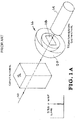
- Transmission detector 14 is an energy collector that measures the total gamma-rays passing through the object and the first detector 16, which consists of a piece (typically a foil) of the material/isotope that is being sought in the container, i.e., a foil 18 of U235 in this example.
- the foil of U235 in detector 16 is surrounded by a large area, gamma-ray spectrometer 20 that measures the spectrum of the photons scattered by the U235 foil 18. If U235 is present in the cargo container in quantities greater than a few grams, then the resonant photons will be removed from the interrogating gamma-ray beam and the gamma-ray spectrometer surrounding the foil of U235 will not see any resonant photons. As depicted in Figure 1B , light scattered by the interrogating foil will consist of non-NRF photons and particles 22 such as Compton scattered photons, Delbruck photons and miscellaneous energetic particles.
- FIG. 2A shows a cargo container 30, that includes U235 material 32 that is interrogated by a polychromatic beam 34 that includes light resonant at the U235 line.
- Figure 2B spectroscopy of the scattered light shows only non-NRF photons and particles 36 and thereby reveals the absence of NRF photons and thus the presence of U235 material in the container. While this method in principle works, it has some significant limitations, in particular, it requires gamma-ray spectroscopy of the scattered photons to be effective.
- Gamma-ray spectroscopy is difficult and is accomplished in nearly all cases by collecting one gamma-ray at a time and analyzing the total energy of that photon. This can work for beams that have photons distributed evenly in time, e.g., those coming from a Bremsstrahlung source.
- Bremsstrahlung sources have been shown to be ill-suited for transmission based NRF detection schemes due to their wide bandwidth and beam divergence which are both ill-matched to NRF detection requirements (Pruet et al. paper).
- MEGa-ray beams are well suited to transmission detection due to their narrow bandwidth and low divergence (100x smaller than Bremsstrahlung); however, these sources by their nature produce large bursts of photons, up to 10E10 per pulse at rates of 10's to 100's of times per second. MEGa-ray sources are ill-matched to single photon counting based gamma-ray spectroscopy.
- WO 2007/038527 discloses utilizing novel laser-based, high- brightness, high-spatial-resolution, pencil-beam sources of spectrally pure hard x-ray and gamma- ray radiation to induce resonant scattering in specific nuclei, i.e., nuclear resonance fluorescence. By monitoring such fluorescence as a function of beam position, it is possible to image in either two dimensions or three dimensions, the position and concentration of individual isotopes in a specific material configuration.
- Such methods of the present invention material identification, spatial resolution of material location and ability to locate and identify materials shielded by other materials, such as, for example, behind a lead wall.
- the foundation of the present invention is the generation of quasimonochromatic high-energy x-ray (100's of keV) and gamma-ray (greater than about 1 MeV) radiation via the collision of intense laser pulses from relativistic electrons.
- Such a process as utilized herein, i.e., Thomson scattering or inverse-Compton scattering produces beams having diameters from about 1 micron to about 100 microns of high-energy photons with a bandwidth of ⁇ E/E of approximately 10E -3 .
- NRF nuclear resonance fluorescence
- MEGa-rays inverse-Compton scattering sources of mono-energetic gamma-rays
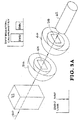
- FIG. 3A shows an embodiment of the present invention including a detector arrangement that consists not of two detectors downstream from the object under observation but instead three.
- the latter detector which operates as a beam monitor, is an integrating detector that monitors the total beam power arriving at its surface.
- This transmission detector can, e.g., be identical to the latter detector in the Bertozzi scheme, which is described in U.S. 2006/0188060 A1 .
- the first detector and the middle detector each include an integrating detector surrounding a foil.
- the foils of these two detectors are made of the same atomic material, but each foil is a different isotope, e.g., the first foil may comprise U235 and second foil may comprise U238.
- the integrating detectors surrounding these pieces of foil measure the total power scattered from the foil and can be similar in composition to the final beam monitor. Non-resonant photons will, after calibration, scatter equally from both foils, i.e., Compton, Delbruck, etc., and are not, to first order, dependent upon the number of nucleons in the isotope but are a function of the atomic element.
- the first foil will produce resonant photons as well as the non-resonant photons and scatter and thus more energy will emanate from the first foil than the second foil.
- a variety of methods for diagnosing the content of an interrogated object are provided herein and are within the scope of the present invention.
- the ratio of the energy scattered by each foil or the difference in energy scattered by each foil can be used to determine not only the presence of the material in the object under interrogation, but the exact ratio or difference is a function of the amount of material present, thus this detector arrangement can also provide quantitative assay information.
- MEGa-ray beams and NRF to determine with high spatial resolution (microns) the location of specific isotopes.
- DINO Dual Isotope Notch Observer
- FIG. 3A shows an embodiment of the present invention where there is no U235 or U238 in the path of the beam.
- MEGa-ray probe beam 50 is tuned at a U235 NRF line.
- the path of beam 50 as it traverses container 52 does not intersect any U235 or U238 material.
- beam 50 After passing though container 52, beam 50 propagates to and through a first foil 54, which is surrounded by an integrating detector 56.
- beam 50 After passing through fo i l 54, beam 50 propagates to and through a second foil 58, which is surrounded by an integrating detector 60.
- beam 50 propagates onto an integrating detector 62.
- U235 foil 54 produces a larger amount of NRF than it would have if beam 50 had encountered U235 in its path through container 52. If a sufficient quantity of U235 had been present in the path of beam 50 within container 52, such that all of the resonant photons in beam 50 had been removed, then, after normalization of the signals at each detector to account for attenuation losses, the amount of non-resonant photons and scatter from foils 54 and 58 would have, to first order, been the same.
- FIG. 3A there is no U235 (or U238) within the beam path through the container, and therefore, in addition to the non-resonant photons and scattered particles, the integrating detector collects resonance produced by the interaction of probe beam 50 with the U235 in foil 54.
- Figure 3B depicts the signals produced by integrating detectors 56 and 58 in the example of Figure 3A .
- the elements of Figure 4A are identical in all respects to those of Figure 3A , except that a quantity of U235 material 64 is in the path of beam 50 as it passes through container 52. In this example, the amount of U235 is sufficient to remove all of the resonant photons from beam 50, such that there is no production of U235 NRF from foil 54, as depicted in Figure 4B .
- the present invention is capable of producing U235 NRF in foil 54 even in the presence of U235 within the path of beam 50 through container 52.
- the amount of U235 NRF produced by foil 54 is less than that produced when beam 50 encounters no U235 in its path through container 54, the amount of U235 that is produced is indicative of the quantity of that material in the path of beam 50.
- an image can be obtained of the U235 material within container 52.
- Other techniques for obtaining a 2D and 3D image are discussed below, and still others will be apparent to those skilled in the art based on the descriptions herein.
- the present invention uses examples for determining the presence, assay and image of U235, the present invention can be used for the same purposes in applications with other materials.
- Figure 5 illustrates another example where, after exiting an object under test (not shown), a probe beam 70, passes through U238 foil 72 and then through U235 foil 82 before propagating onto the beam monitoring detector 90.
- the integrating detector 74 shown in cross-section, positioned near foil 72, is substantially similar, in this example, to the detector 84 positioned near foil 82. Integrating detector 74 is formed of a scintillator 76 and two photomultipliers 77 and 78. A Compton shield 79 is positioned between foil 72 and scintillator 76.
- FIG. 6A illustrates an embodiment that uses a single rotating foil rather that the dual foils described supra.
- MEGa-ray beam 100 passes through rotating foil 102 and impinges on the integrating detector 106.
- An integrating detector 104 similar to the detectors 74 and 84 of Figure 5 , is located near rotating foil 102
- Figure 6B shows a front view of the rotating foil 102.
- one half 102' of the rotating foil comprises U235 and the other half 102" comprises U238.
- the beam 100 is pulsed at a fixed rate and the rotating foil 102 rotates at a fixed rate that is one half of the rate of pulses if beam 100. At such a rotational rate, the beam 100 will pass through the U235 portion in one pulse and in the next pulse, beam 100 will pass through the U238 portion.
- Figure 7 is an example where a portion of a finite area MEGa-ray beam 120 simultaneously passes through U235 piece 122 and U238 piece 124.
- the portion of beam 120 that passes through U235 piece 122 propagates onto integrating detector 126 and the portion of beam 120 that passes through U238 piece 124 propagates onto integrating detector 128.
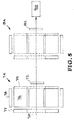
- Figure 8 illustrates a finite area MEGa-ray beam 140 that propagates through pixels 141-146 of U235 material in line with pixels 151-156 of U238 material.
- This beam will completely cover any U235 material that has a diameter of less than the beam diameter. For example, if the beam diameter 140' is 1 cm and a U235 piece 148 has a diameter of .5 cm, then U235 piece 148 will be completely covered by beam 140.
- a separate integrating detector (not shown) is positioned to measure U235 NRF and non-resonant photons and particles for each of pixels 141-146 of U235 material and pixels 151-156 of U238 material.
- a separate integrating detector of integrating detectors 161-166 is positioned to measure the beam portion that passes through each pixel pair.
- the portion of beam 140 that passes through pixel 141 will then pass through pixel 151 and will propagate onto integrating detector 161.
- pixels 141-146 and pixels 151-156 are depicted as a two dimensional array, each pixel can be a part of an array of pixels extending perpendicular to the plane of the page to create a three dimensional pixel array.
- This exemplary configuration instantly provides a complete 2 dimensional image of any piece of U235 that is smaller than the diameter of beam 140. Such a beam can be moved relative to a larger piece of U235 to obtain an image of such piece.
- the beam and the piece of U235 can be moved relative to one another to obtain a 3 dimensional image of the U235.
- the beam and its alignment to the pixel arrays can be held constant as a unit, and the whole unit can be moved relative to obtain an image of the piece of U235.
- FIG. 3A the MEGa-ray, which is tuned to a U235 NRF line, passes through the container without encountering any U235. If the beam was not tuned to either the U235 or the U238 NRF line, the amount of signal collected by each integrating detector would be about the same. There would be some reduction in power by absorption and scattering as the beam propagates through the first foil. Therefore, the two signals are normalized. If the beam is then tuned to a NRF line of U235, the difference between the signal levels in each detector is produced by the NRF from the U235 content of the first foil. This difference will not change if the entire container is removed.
- the detection system can be set up and aligned and then targets, such as shipping containers, can be moved into the beam path. If the beam path does intersect material having U235 content, then the signal difference will be determined by the amount of U235 through which the beam passes. Placing this difference on a logarithmic scale will reveal small changes in the amount of U235 NRF produced signal collected by the integrating detector proximate to the U235 foil. This enables a variety of data analysis methods of varying degree of precision. For example, simply measuring the amount of signal collected by the U235 detector on resonance before and during interaction with a U235 target will show a signal difference that is dependent on the amount of U235 encountered.
- a measurement is made of the amount of signal collected by the U235 detector and the U238 detector, on resonance, before and during interaction with a U235 target.
- the signals can first be normalized a variety of ways, including the substitution of a U238 foil for the U235 foil, or by tuning the MEGa-ray beam to be off resonance.
- the difference between the two signals on the U235 resonance is dependent on the amount of U235 encountered.
- a difference is determined between (i) the ratio of the U235 detector signal to the third detector and (ii) the ratio of the U238 detector signal to the third detector.
- depiction of the results on a log scale reveals much smaller changes than on a linear scale.
- Other signal analysis methods will now be apparent to those skilled in the art based on these examples.
- Embodiments of the invention can be used to rapidly determine the isotope content of moving targets such as those as to be used in the Laser Inertial Fusion-Fission Energy (LIFE) Project at the Lawrence Livermore National Laboratory or in a pebble bed reactor. If cases where the object is moving, configurations of the invention are usable to measure the Doppler shift for determination of velocities
- LIFE Laser Inertial Fusion-Fission Energy
Landscapes
- Physics & Mathematics (AREA)
- General Physics & Mathematics (AREA)
- Life Sciences & Earth Sciences (AREA)
- General Health & Medical Sciences (AREA)
- Analytical Chemistry (AREA)
- Biochemistry (AREA)
- Chemical & Material Sciences (AREA)
- Health & Medical Sciences (AREA)
- Immunology (AREA)
- Pathology (AREA)
- High Energy & Nuclear Physics (AREA)
- General Life Sciences & Earth Sciences (AREA)
- Geophysics (AREA)
- Analysing Materials By The Use Of Radiation (AREA)
- Measurement Of Radiation (AREA)
Priority Applications (1)
| Application Number | Priority Date | Filing Date | Title |
|---|---|---|---|
| PL15153435T PL2889610T3 (pl) | 2009-07-21 | 2010-07-15 | Fluorescencja rezonansu jądrowego techniką podwójnego izotopu do identyfikacji izotopowej, analizy i obrazowania z zastosowaniem źródeł monoenergetycznego promieniowania gamma |
Applications Claiming Priority (3)
| Application Number | Priority Date | Filing Date | Title |
|---|---|---|---|
| US12/506,639 US8369480B2 (en) | 2005-09-26 | 2009-07-21 | Dual isotope notch observer for isotope identification, assay and imaging with mono-energetic gamma-ray sources |
| EP10836341.7A EP2524209A4 (en) | 2009-07-21 | 2010-07-15 | DOUBLE ISOTOPE NICKEL OBSERVER FOR IDENTIFICATION, ASSAY AND IMAGING OF ISOTOPES WITH MONO-ENERGY GAMMA RAY SOURCES |
| PCT/US2010/042084 WO2011071563A1 (en) | 2009-07-21 | 2010-07-15 | Dual isotope notch observer for isotope identification, assay and imaging with mono-energetic gamma-ray sources |
Related Parent Applications (1)
| Application Number | Title | Priority Date | Filing Date |
|---|---|---|---|
| EP10836341.7A Division EP2524209A4 (en) | 2009-07-21 | 2010-07-15 | DOUBLE ISOTOPE NICKEL OBSERVER FOR IDENTIFICATION, ASSAY AND IMAGING OF ISOTOPES WITH MONO-ENERGY GAMMA RAY SOURCES |
Publications (2)
| Publication Number | Publication Date |
|---|---|
| EP2889610A1 EP2889610A1 (en) | 2015-07-01 |
| EP2889610B1 true EP2889610B1 (en) | 2020-04-22 |
Family
ID=44145849
Family Applications (2)
| Application Number | Title | Priority Date | Filing Date |
|---|---|---|---|
| EP15153435.1A Active EP2889610B1 (en) | 2009-07-21 | 2010-07-15 | Dual isotope nuclear resonance fluorescence for isotope identification, assay and imaging with mono-energetic gamma-ray sources |
| EP10836341.7A Withdrawn EP2524209A4 (en) | 2009-07-21 | 2010-07-15 | DOUBLE ISOTOPE NICKEL OBSERVER FOR IDENTIFICATION, ASSAY AND IMAGING OF ISOTOPES WITH MONO-ENERGY GAMMA RAY SOURCES |
Family Applications After (1)
| Application Number | Title | Priority Date | Filing Date |
|---|---|---|---|
| EP10836341.7A Withdrawn EP2524209A4 (en) | 2009-07-21 | 2010-07-15 | DOUBLE ISOTOPE NICKEL OBSERVER FOR IDENTIFICATION, ASSAY AND IMAGING OF ISOTOPES WITH MONO-ENERGY GAMMA RAY SOURCES |
Country Status (7)
| Country | Link |
|---|---|
| US (1) | US8369480B2 (cg-RX-API-DMAC7.html) |
| EP (2) | EP2889610B1 (cg-RX-API-DMAC7.html) |
| JP (2) | JP2013511022A (cg-RX-API-DMAC7.html) |
| DK (1) | DK2889610T3 (cg-RX-API-DMAC7.html) |
| ES (1) | ES2798083T3 (cg-RX-API-DMAC7.html) |
| PL (1) | PL2889610T3 (cg-RX-API-DMAC7.html) |
| WO (1) | WO2011071563A1 (cg-RX-API-DMAC7.html) |
Families Citing this family (8)
| Publication number | Priority date | Publication date | Assignee | Title |
|---|---|---|---|---|
| US9205463B2 (en) * | 2005-09-26 | 2015-12-08 | Lawrence Livermore National Security, Llc | Isotope specific arbitrary material sorter |
| US8934608B2 (en) * | 2005-09-26 | 2015-01-13 | Lawrence Livermore National Security, Llc | High flux, narrow bandwidth compton light sources via extended laser-electron interactions |
| WO2013055449A2 (en) * | 2011-08-22 | 2013-04-18 | Lawrence Livermore National Security, Llc | Isotope specific arbitrary material sorter and flow meter |
| JP5403767B2 (ja) * | 2009-03-05 | 2014-01-29 | 独立行政法人産業技術総合研究所 | 原子核共鳴蛍光散乱を用いた非破壊検査システム |
| US9706631B2 (en) | 2013-05-10 | 2017-07-11 | Lawrence Livermore National Security, Llc | Modulated method for efficient, narrow-bandwidth, laser Compton X-ray and gamma-ray sources |
| CA2951639C (en) | 2014-05-08 | 2021-01-26 | Lawrence Livermore National Security, Llc | Methods for 2-color radiography with laser-compton x-ray sources |
| NZ727184A (en) | 2014-05-08 | 2017-12-22 | L Livermore Nat Security Llc | Ultralow-dose, feedback imaging with laser-compton x-ray and laser-compton gamma-ray sources |
| CN119781000B (zh) * | 2025-03-12 | 2025-05-23 | 中国工程物理研究院激光聚变研究中心 | 一种入射icf靶丸x射线辐射流的原位测量方法及装置 |
Family Cites Families (21)
| Publication number | Priority date | Publication date | Assignee | Title |
|---|---|---|---|---|
| AU454745B2 (en) | 1970-05-06 | 1974-10-21 | Aust. Atomic Energy Commission | Applications of nuclear resonance fluorescence of gamma rays to elemental analysis |
| US5040200A (en) | 1989-05-08 | 1991-08-13 | Scientific Innovations, Inc. | Gamma-gamma resonance in activation analysis, and particularly, its application to detection of nitrogen based explosives in luggage |
| US5323004A (en) | 1989-05-08 | 1994-06-21 | Scientific Innovations, Inc. | Nuclear resonances in activation analysis, and particularly, its application to detection of nitrogen based explosives in luggage |
| WO1992003722A1 (en) | 1990-08-15 | 1992-03-05 | Massachusetts Institute Of Technology | Detection of explosives and other materials using resonance fluorescence, resonance absorption, and other electromagnetic processes with bremsstrahlung radiation |
| US5115459A (en) | 1990-08-15 | 1992-05-19 | Massachusetts Institute Of Technology | Explosives detection using resonance fluorescence of bremsstrahlung radiation |
| CA2086054C (en) * | 1992-12-22 | 2003-02-25 | Paul Wesley Schmor | Nitrogen detector and method of detecting |
| US6236050B1 (en) | 1996-02-02 | 2001-05-22 | TüMER TüMAY O. | Method and apparatus for radiation detection |
| US6442233B1 (en) | 1998-06-18 | 2002-08-27 | American Science And Engineering, Inc. | Coherent x-ray scatter inspection system with sidescatter and energy-resolved detection |
| JP2001141672A (ja) * | 1999-11-12 | 2001-05-25 | Matsushita Electric Ind Co Ltd | X線撮像処理装置 |
| US6684010B1 (en) | 2000-03-03 | 2004-01-27 | Digital Optics Corp. | Wavelength compensated optical wavelength division coupler and associated methods |
| US6661818B1 (en) | 2000-04-05 | 2003-12-09 | Digital Optics Corporation | Etalon, a wavelength monitor/locker using the etalon and associated methods |
| US7356115B2 (en) | 2002-12-04 | 2008-04-08 | Varian Medical Systems Technology, Inc. | Radiation scanning units including a movable platform |
| US7064899B2 (en) | 2002-08-30 | 2006-06-20 | Digital Optics Corp. | Reduced loss diffractive structure |
| WO2005081017A1 (en) | 2003-11-24 | 2005-09-01 | Passport Systems, Inc. | Adaptive scanning of materials using nuclear resonancee fluorescence imaging |
| US20090196397A1 (en) | 2007-12-27 | 2009-08-06 | Passport Systems, Inc. | Methods and systems for computer tomography of nuclear isotopes using nuclear resonance fluorescence |
| US20050179911A1 (en) | 2004-02-17 | 2005-08-18 | Digital Optics Corporation | Aspheric diffractive reference for interferometric lens metrology |
| US7486769B2 (en) | 2004-06-03 | 2009-02-03 | Brondo Jr Joseph H | Advanced multi-resonant, multi-mode gamma beam detection and imaging system for explosives, special nuclear material (SNM), high-z materials, and other contraband |
| JP5054518B2 (ja) * | 2004-07-08 | 2012-10-24 | パスポート システムズ, インク. | 物質の平均原子番号及び質量を求めるための方法及びシステム |
| CA2597731A1 (en) | 2005-02-22 | 2007-08-02 | Passport Systems, Inc. | Use of nearly monochromatic and tunable photon sources with nuclear resonance fluorescence in non-intrusive inspection of containers for material detection and imaging |
| JP5368795B2 (ja) * | 2005-09-26 | 2013-12-18 | ローレンス リヴァーモア ナショナル セキュリティ,エルエルシー | レーザーによるトムソン放射による核共鳴蛍光を用いた同位体イメージング |
| US8023618B2 (en) | 2007-12-12 | 2011-09-20 | Passport Systems, Inc. | Methods and apparatus for the identification of molecular and crystalline materials by the doppler broadening of nuclear states bound in molecules, crystals and mixtures using nuclear resonance fluorescence |
-
2009
- 2009-07-21 US US12/506,639 patent/US8369480B2/en active Active
-
2010
- 2010-07-15 ES ES15153435T patent/ES2798083T3/es active Active
- 2010-07-15 JP JP2012521682A patent/JP2013511022A/ja active Pending
- 2010-07-15 DK DK15153435.1T patent/DK2889610T3/da active
- 2010-07-15 EP EP15153435.1A patent/EP2889610B1/en active Active
- 2010-07-15 WO PCT/US2010/042084 patent/WO2011071563A1/en not_active Ceased
- 2010-07-15 EP EP10836341.7A patent/EP2524209A4/en not_active Withdrawn
- 2010-07-15 PL PL15153435T patent/PL2889610T3/pl unknown
-
2015
- 2015-01-13 JP JP2015004120A patent/JP5957099B2/ja active Active
Non-Patent Citations (1)
| Title |
|---|
| None * |
Also Published As
| Publication number | Publication date |
|---|---|
| JP5957099B2 (ja) | 2016-07-27 |
| US20130003924A1 (en) | 2013-01-03 |
| ES2798083T3 (es) | 2020-12-09 |
| WO2011071563A9 (en) | 2012-02-16 |
| DK2889610T3 (da) | 2020-06-15 |
| EP2524209A4 (en) | 2014-08-20 |
| PL2889610T3 (pl) | 2020-11-16 |
| EP2889610A1 (en) | 2015-07-01 |
| JP2013511022A (ja) | 2013-03-28 |
| WO2011071563A1 (en) | 2011-06-16 |
| EP2524209A1 (en) | 2012-11-21 |
| JP2015121547A (ja) | 2015-07-02 |
| US8369480B2 (en) | 2013-02-05 |
Similar Documents
| Publication | Publication Date | Title |
|---|---|---|
| EP2889610B1 (en) | Dual isotope nuclear resonance fluorescence for isotope identification, assay and imaging with mono-energetic gamma-ray sources | |
| EP2589954B1 (en) | Articles detection device and detection method thereof | |
| CN101340771B (zh) | 一种光中子转换靶 | |
| EP2287636B1 (en) | Method and system for inspecting special nuclear material | |
| EP2589955B1 (en) | Articles detecting device and detecting method thereof | |
| US20080179502A1 (en) | Methods and systems for determining the average atomic number and mass of materials | |
| US20090175401A1 (en) | Non-intrusive method to identify presence of nuclear materials using energetic prompt neutrons from neutron-induced fission | |
| GB2299251A (en) | Detecting crystalline material using X-ray diffraction | |
| Lintereur et al. | Neutron and gamma ray pulse shape discrimination with polyvinyltoluene | |
| US8588370B2 (en) | Article inspection device and inspection method | |
| EP2074413B1 (en) | Method for detecting nitrogenous materials via gamma-resonance absorption (gra) | |
| CA2861694C (en) | Methods and apparatuses for measuring effective atomic number of an object | |
| EP2171723B1 (en) | Non-intrusive method to identify presence of nuclear materials using energetic prompt neutrons from photon-induced fission | |
| US7949097B2 (en) | Methods and apparatus for the identification of materials using photons scattered from the nuclear “PYGMY resonance” | |
| Quiter | Examining 239Pu and 240Pu nuclear resonance fluorescence measurements on spent fuel for nuclear safeguards | |
| Vartsky et al. | Detectors for the gamma-ray resonant absorption (GRA) method of explosives detection in cargo: a comparative study | |
| Warren et al. | On the Search for Nuclear Resonance Fluorescence Signatures of $^{235}{\rm U} $ and $^{238}{\rm U} $ Above 3 MeV | |
| Jones et al. | Enhanced Photofission-Based, Coincidence/Multiplicity Inspection Measurements | |
| RU2502087C2 (ru) | Способ обнаружения объектов ядерных технологий радиозондированием | |
| Keegan et al. | meaSuRemenT oF TaggeD neuTRon FiSSion aniSoTRoPY | |
| Warren et al. | Potential National Security Applications of Nuclear Resonance Fluorescence Methods | |
| HK1127640A (en) | Method and system for contraband detection using a photoneutron x-ray |
Legal Events
| Date | Code | Title | Description |
|---|---|---|---|
| PUAI | Public reference made under article 153(3) epc to a published international application that has entered the european phase |
Free format text: ORIGINAL CODE: 0009012 |
|
| 17P | Request for examination filed |
Effective date: 20150202 |
|
| AC | Divisional application: reference to earlier application |
Ref document number: 2524209 Country of ref document: EP Kind code of ref document: P |
|
| AK | Designated contracting states |
Kind code of ref document: A1 Designated state(s): AL AT BE BG CH CY CZ DE DK EE ES FI FR GB GR HR HU IE IS IT LI LT LU LV MC MK MT NL NO PL PT RO SE SI SK SM TR |
|
| R17P | Request for examination filed (corrected) |
Effective date: 20151229 |
|
| RBV | Designated contracting states (corrected) |
Designated state(s): AL AT BE BG CH CY CZ DE DK EE ES FI FR GB GR HR HU IE IS IT LI LT LU LV MC MK MT NL NO PL PT RO SE SI SK SM TR |
|
| REG | Reference to a national code |
Ref country code: DE Ref legal event code: R079 Ref document number: 602010064051 Country of ref document: DE Free format text: PREVIOUS MAIN CLASS: G01N0023220000 Ipc: G01N0023040000 |
|
| GRAP | Despatch of communication of intention to grant a patent |
Free format text: ORIGINAL CODE: EPIDOSNIGR1 |
|
| STAA | Information on the status of an ep patent application or granted ep patent |
Free format text: STATUS: GRANT OF PATENT IS INTENDED |
|
| RIC1 | Information provided on ipc code assigned before grant |
Ipc: G01V 5/00 20060101ALI20190710BHEP Ipc: G01N 23/04 20180101AFI20190710BHEP |
|
| INTG | Intention to grant announced |
Effective date: 20190801 |
|
| INTG | Intention to grant announced |
Effective date: 20190801 |
|
| GRAS | Grant fee paid |
Free format text: ORIGINAL CODE: EPIDOSNIGR3 |
|
| GRAJ | Information related to disapproval of communication of intention to grant by the applicant or resumption of examination proceedings by the epo deleted |
Free format text: ORIGINAL CODE: EPIDOSDIGR1 |
|
| GRAL | Information related to payment of fee for publishing/printing deleted |
Free format text: ORIGINAL CODE: EPIDOSDIGR3 |
|
| STAA | Information on the status of an ep patent application or granted ep patent |
Free format text: STATUS: REQUEST FOR EXAMINATION WAS MADE |
|
| INTC | Intention to grant announced (deleted) | ||
| GRAR | Information related to intention to grant a patent recorded |
Free format text: ORIGINAL CODE: EPIDOSNIGR71 |
|
| STAA | Information on the status of an ep patent application or granted ep patent |
Free format text: STATUS: GRANT OF PATENT IS INTENDED |
|
| GRAA | (expected) grant |
Free format text: ORIGINAL CODE: 0009210 |
|
| STAA | Information on the status of an ep patent application or granted ep patent |
Free format text: STATUS: THE PATENT HAS BEEN GRANTED |
|
| AC | Divisional application: reference to earlier application |
Ref document number: 2524209 Country of ref document: EP Kind code of ref document: P |
|
| AK | Designated contracting states |
Kind code of ref document: B1 Designated state(s): AL AT BE BG CH CY CZ DE DK EE ES FI FR GB GR HR HU IE IS IT LI LT LU LV MC MK MT NL NO PL PT RO SE SI SK SM TR |
|
| INTG | Intention to grant announced |
Effective date: 20200313 |
|
| REG | Reference to a national code |
Ref country code: CH Ref legal event code: EP |
|
| REG | Reference to a national code |
Ref country code: IE Ref legal event code: FG4D |
|
| REG | Reference to a national code |
Ref country code: DE Ref legal event code: R096 Ref document number: 602010064051 Country of ref document: DE |
|
| REG | Reference to a national code |
Ref country code: AT Ref legal event code: REF Ref document number: 1260782 Country of ref document: AT Kind code of ref document: T Effective date: 20200515 |
|
| REG | Reference to a national code |
Ref country code: CH Ref legal event code: NV Representative=s name: DR. LUSUARDI AG, CH Ref country code: DK Ref legal event code: T3 Effective date: 20200609 |
|
| REG | Reference to a national code |
Ref country code: NL Ref legal event code: FP |
|
| REG | Reference to a national code |
Ref country code: SE Ref legal event code: TRGR |
|
| REG | Reference to a national code |
Ref country code: NO Ref legal event code: T2 Effective date: 20200422 |
|
| REG | Reference to a national code |
Ref country code: LT Ref legal event code: MG4D |
|
| PG25 | Lapsed in a contracting state [announced via postgrant information from national office to epo] |
Ref country code: GR Free format text: LAPSE BECAUSE OF FAILURE TO SUBMIT A TRANSLATION OF THE DESCRIPTION OR TO PAY THE FEE WITHIN THE PRESCRIBED TIME-LIMIT Effective date: 20200723 Ref country code: FI Free format text: LAPSE BECAUSE OF FAILURE TO SUBMIT A TRANSLATION OF THE DESCRIPTION OR TO PAY THE FEE WITHIN THE PRESCRIBED TIME-LIMIT Effective date: 20200422 Ref country code: IS Free format text: LAPSE BECAUSE OF FAILURE TO SUBMIT A TRANSLATION OF THE DESCRIPTION OR TO PAY THE FEE WITHIN THE PRESCRIBED TIME-LIMIT Effective date: 20200822 Ref country code: LT Free format text: LAPSE BECAUSE OF FAILURE TO SUBMIT A TRANSLATION OF THE DESCRIPTION OR TO PAY THE FEE WITHIN THE PRESCRIBED TIME-LIMIT Effective date: 20200422 Ref country code: PT Free format text: LAPSE BECAUSE OF FAILURE TO SUBMIT A TRANSLATION OF THE DESCRIPTION OR TO PAY THE FEE WITHIN THE PRESCRIBED TIME-LIMIT Effective date: 20200824 |
|
| REG | Reference to a national code |
Ref country code: AT Ref legal event code: UEP Ref document number: 1260782 Country of ref document: AT Kind code of ref document: T Effective date: 20200422 |
|
| PG25 | Lapsed in a contracting state [announced via postgrant information from national office to epo] |
Ref country code: LV Free format text: LAPSE BECAUSE OF FAILURE TO SUBMIT A TRANSLATION OF THE DESCRIPTION OR TO PAY THE FEE WITHIN THE PRESCRIBED TIME-LIMIT Effective date: 20200422 Ref country code: HR Free format text: LAPSE BECAUSE OF FAILURE TO SUBMIT A TRANSLATION OF THE DESCRIPTION OR TO PAY THE FEE WITHIN THE PRESCRIBED TIME-LIMIT Effective date: 20200422 Ref country code: BG Free format text: LAPSE BECAUSE OF FAILURE TO SUBMIT A TRANSLATION OF THE DESCRIPTION OR TO PAY THE FEE WITHIN THE PRESCRIBED TIME-LIMIT Effective date: 20200722 |
|
| REG | Reference to a national code |
Ref country code: ES Ref legal event code: FG2A Ref document number: 2798083 Country of ref document: ES Kind code of ref document: T3 Effective date: 20201209 |
|
| PG25 | Lapsed in a contracting state [announced via postgrant information from national office to epo] |
Ref country code: AL Free format text: LAPSE BECAUSE OF FAILURE TO SUBMIT A TRANSLATION OF THE DESCRIPTION OR TO PAY THE FEE WITHIN THE PRESCRIBED TIME-LIMIT Effective date: 20200422 |
|
| REG | Reference to a national code |
Ref country code: DE Ref legal event code: R097 Ref document number: 602010064051 Country of ref document: DE |
|
| PG25 | Lapsed in a contracting state [announced via postgrant information from national office to epo] |
Ref country code: CZ Free format text: LAPSE BECAUSE OF FAILURE TO SUBMIT A TRANSLATION OF THE DESCRIPTION OR TO PAY THE FEE WITHIN THE PRESCRIBED TIME-LIMIT Effective date: 20200422 Ref country code: SM Free format text: LAPSE BECAUSE OF FAILURE TO SUBMIT A TRANSLATION OF THE DESCRIPTION OR TO PAY THE FEE WITHIN THE PRESCRIBED TIME-LIMIT Effective date: 20200422 Ref country code: EE Free format text: LAPSE BECAUSE OF FAILURE TO SUBMIT A TRANSLATION OF THE DESCRIPTION OR TO PAY THE FEE WITHIN THE PRESCRIBED TIME-LIMIT Effective date: 20200422 |
|
| PG25 | Lapsed in a contracting state [announced via postgrant information from national office to epo] |
Ref country code: SK Free format text: LAPSE BECAUSE OF FAILURE TO SUBMIT A TRANSLATION OF THE DESCRIPTION OR TO PAY THE FEE WITHIN THE PRESCRIBED TIME-LIMIT Effective date: 20200422 Ref country code: MC Free format text: LAPSE BECAUSE OF FAILURE TO SUBMIT A TRANSLATION OF THE DESCRIPTION OR TO PAY THE FEE WITHIN THE PRESCRIBED TIME-LIMIT Effective date: 20200422 |
|
| PLBE | No opposition filed within time limit |
Free format text: ORIGINAL CODE: 0009261 |
|
| STAA | Information on the status of an ep patent application or granted ep patent |
Free format text: STATUS: NO OPPOSITION FILED WITHIN TIME LIMIT |
|
| 26N | No opposition filed |
Effective date: 20210125 |
|
| PG25 | Lapsed in a contracting state [announced via postgrant information from national office to epo] |
Ref country code: LU Free format text: LAPSE BECAUSE OF NON-PAYMENT OF DUE FEES Effective date: 20200715 |
|
| PG25 | Lapsed in a contracting state [announced via postgrant information from national office to epo] |
Ref country code: SI Free format text: LAPSE BECAUSE OF FAILURE TO SUBMIT A TRANSLATION OF THE DESCRIPTION OR TO PAY THE FEE WITHIN THE PRESCRIBED TIME-LIMIT Effective date: 20200422 |
|
| PG25 | Lapsed in a contracting state [announced via postgrant information from national office to epo] |
Ref country code: IE Free format text: LAPSE BECAUSE OF NON-PAYMENT OF DUE FEES Effective date: 20200715 |
|
| PG25 | Lapsed in a contracting state [announced via postgrant information from national office to epo] |
Ref country code: TR Free format text: LAPSE BECAUSE OF FAILURE TO SUBMIT A TRANSLATION OF THE DESCRIPTION OR TO PAY THE FEE WITHIN THE PRESCRIBED TIME-LIMIT Effective date: 20200422 Ref country code: MT Free format text: LAPSE BECAUSE OF FAILURE TO SUBMIT A TRANSLATION OF THE DESCRIPTION OR TO PAY THE FEE WITHIN THE PRESCRIBED TIME-LIMIT Effective date: 20200422 Ref country code: CY Free format text: LAPSE BECAUSE OF FAILURE TO SUBMIT A TRANSLATION OF THE DESCRIPTION OR TO PAY THE FEE WITHIN THE PRESCRIBED TIME-LIMIT Effective date: 20200422 |
|
| PG25 | Lapsed in a contracting state [announced via postgrant information from national office to epo] |
Ref country code: MK Free format text: LAPSE BECAUSE OF FAILURE TO SUBMIT A TRANSLATION OF THE DESCRIPTION OR TO PAY THE FEE WITHIN THE PRESCRIBED TIME-LIMIT Effective date: 20200422 |
|
| PGFP | Annual fee paid to national office [announced via postgrant information from national office to epo] |
Ref country code: PL Payment date: 20250618 Year of fee payment: 16 |
|
| PGFP | Annual fee paid to national office [announced via postgrant information from national office to epo] |
Ref country code: NL Payment date: 20250726 Year of fee payment: 16 |
|
| PGFP | Annual fee paid to national office [announced via postgrant information from national office to epo] |
Ref country code: ES Payment date: 20250801 Year of fee payment: 16 |
|
| PGFP | Annual fee paid to national office [announced via postgrant information from national office to epo] |
Ref country code: DE Payment date: 20250729 Year of fee payment: 16 Ref country code: DK Payment date: 20250725 Year of fee payment: 16 |
|
| PGFP | Annual fee paid to national office [announced via postgrant information from national office to epo] |
Ref country code: NO Payment date: 20250729 Year of fee payment: 16 |
|
| PGFP | Annual fee paid to national office [announced via postgrant information from national office to epo] |
Ref country code: IT Payment date: 20250721 Year of fee payment: 16 |
|
| PGFP | Annual fee paid to national office [announced via postgrant information from national office to epo] |
Ref country code: BE Payment date: 20250728 Year of fee payment: 16 Ref country code: GB Payment date: 20250728 Year of fee payment: 16 |
|
| PGFP | Annual fee paid to national office [announced via postgrant information from national office to epo] |
Ref country code: FR Payment date: 20250725 Year of fee payment: 16 Ref country code: AT Payment date: 20250620 Year of fee payment: 16 |
|
| PGFP | Annual fee paid to national office [announced via postgrant information from national office to epo] |
Ref country code: CH Payment date: 20250801 Year of fee payment: 16 Ref country code: SE Payment date: 20250727 Year of fee payment: 16 |
|
| PGFP | Annual fee paid to national office [announced via postgrant information from national office to epo] |
Ref country code: RO Payment date: 20250701 Year of fee payment: 16 |