EP2589954B1 - Articles detection device and detection method thereof - Google Patents
Articles detection device and detection method thereof Download PDFInfo
- Publication number
- EP2589954B1 EP2589954B1 EP10854001.4A EP10854001A EP2589954B1 EP 2589954 B1 EP2589954 B1 EP 2589954B1 EP 10854001 A EP10854001 A EP 10854001A EP 2589954 B1 EP2589954 B1 EP 2589954B1
- Authority
- EP
- European Patent Office
- Prior art keywords
- article
- scattering
- detector
- photons
- sub
- Prior art date
- Legal status (The legal status is an assumption and is not a legal conclusion. Google has not performed a legal analysis and makes no representation as to the accuracy of the status listed.)
- Active
Links
- 238000001514 detection method Methods 0.000 title description 5
- 230000000694 effects Effects 0.000 claims description 70
- 230000005540 biological transmission Effects 0.000 claims description 46
- 238000004519 manufacturing process Methods 0.000 claims description 46
- 238000007689 inspection Methods 0.000 claims description 29
- 239000011159 matrix material Substances 0.000 claims description 17
- 238000000034 method Methods 0.000 claims description 12
- RYGMFSIKBFXOCR-UHFFFAOYSA-N Copper Chemical compound [Cu] RYGMFSIKBFXOCR-UHFFFAOYSA-N 0.000 claims description 9
- 229910000831 Steel Inorganic materials 0.000 claims description 9
- 229910052802 copper Inorganic materials 0.000 claims description 9
- 239000010949 copper Substances 0.000 claims description 9
- 239000011133 lead Substances 0.000 claims description 9
- 239000010959 steel Substances 0.000 claims description 9
- 229910004611 CdZnTe Inorganic materials 0.000 claims description 4
- 229910002249 LaCl3 Inorganic materials 0.000 claims description 4
- 229910014323 Lanthanum(III) bromide Inorganic materials 0.000 claims description 4
- XKUYOJZZLGFZTC-UHFFFAOYSA-K lanthanum(iii) bromide Chemical group Br[La](Br)Br XKUYOJZZLGFZTC-UHFFFAOYSA-K 0.000 claims description 4
- ICAKDTKJOYSXGC-UHFFFAOYSA-K lanthanum(iii) chloride Chemical compound Cl[La](Cl)Cl ICAKDTKJOYSXGC-UHFFFAOYSA-K 0.000 claims description 4
- 230000003247 decreasing effect Effects 0.000 claims description 3
- 238000007493 shaping process Methods 0.000 claims 1
- 238000001228 spectrum Methods 0.000 description 10
- 239000000463 material Substances 0.000 description 7
- 238000004458 analytical method Methods 0.000 description 5
- 238000003876 NQR spectroscopy Methods 0.000 description 4
- 238000006243 chemical reaction Methods 0.000 description 4
- 238000010894 electron beam technology Methods 0.000 description 4
- 238000005516 engineering process Methods 0.000 description 4
- 239000011824 nuclear material Substances 0.000 description 4
- 229910052739 hydrogen Inorganic materials 0.000 description 3
- 239000001257 hydrogen Substances 0.000 description 3
- IJGRMHOSHXDMSA-UHFFFAOYSA-N Atomic nitrogen Chemical compound N#N IJGRMHOSHXDMSA-UHFFFAOYSA-N 0.000 description 2
- -1 biological weapons Substances 0.000 description 2
- 239000003814 drug Substances 0.000 description 2
- 229940079593 drug Drugs 0.000 description 2
- 239000002360 explosive Substances 0.000 description 2
- 150000002431 hydrogen Chemical class 0.000 description 2
- 230000010354 integration Effects 0.000 description 2
- 239000007788 liquid Substances 0.000 description 2
- 230000035945 sensitivity Effects 0.000 description 2
- 239000000126 substance Substances 0.000 description 2
- 230000005461 Bremsstrahlung Effects 0.000 description 1
- OKTJSMMVPCPJKN-UHFFFAOYSA-N Carbon Chemical compound [C] OKTJSMMVPCPJKN-UHFFFAOYSA-N 0.000 description 1
- UFHFLCQGNIYNRP-UHFFFAOYSA-N Hydrogen Chemical compound [H][H] UFHFLCQGNIYNRP-UHFFFAOYSA-N 0.000 description 1
- 230000002159 abnormal effect Effects 0.000 description 1
- 238000010521 absorption reaction Methods 0.000 description 1
- 238000003491 array Methods 0.000 description 1
- QVGXLLKOCUKJST-UHFFFAOYSA-N atomic oxygen Chemical compound [O] QVGXLLKOCUKJST-UHFFFAOYSA-N 0.000 description 1
- 230000002238 attenuated effect Effects 0.000 description 1
- 229910052799 carbon Inorganic materials 0.000 description 1
- 229910052729 chemical element Inorganic materials 0.000 description 1
- 239000002131 composite material Substances 0.000 description 1
- 230000005684 electric field Effects 0.000 description 1
- 238000002474 experimental method Methods 0.000 description 1
- PCHJSUWPFVWCPO-UHFFFAOYSA-N gold Chemical compound [Au] PCHJSUWPFVWCPO-UHFFFAOYSA-N 0.000 description 1
- 229910052737 gold Inorganic materials 0.000 description 1
- 239000010931 gold Substances 0.000 description 1
- 238000003384 imaging method Methods 0.000 description 1
- 229910052757 nitrogen Inorganic materials 0.000 description 1
- 229910052760 oxygen Inorganic materials 0.000 description 1
- 239000001301 oxygen Substances 0.000 description 1
- 239000007787 solid Substances 0.000 description 1
- 230000002123 temporal effect Effects 0.000 description 1
- WFKWXMTUELFFGS-UHFFFAOYSA-N tungsten Chemical compound [W] WFKWXMTUELFFGS-UHFFFAOYSA-N 0.000 description 1
Images

Classifications
-
- G01V5/22—
-
- G—PHYSICS
- G01—MEASURING; TESTING
- G01N—INVESTIGATING OR ANALYSING MATERIALS BY DETERMINING THEIR CHEMICAL OR PHYSICAL PROPERTIES
- G01N23/00—Investigating or analysing materials by the use of wave or particle radiation, e.g. X-rays or neutrons, not covered by groups G01N3/00 – G01N17/00, G01N21/00 or G01N22/00
- G01N23/02—Investigating or analysing materials by the use of wave or particle radiation, e.g. X-rays or neutrons, not covered by groups G01N3/00 – G01N17/00, G01N21/00 or G01N22/00 by transmitting the radiation through the material
- G01N23/04—Investigating or analysing materials by the use of wave or particle radiation, e.g. X-rays or neutrons, not covered by groups G01N3/00 – G01N17/00, G01N21/00 or G01N22/00 by transmitting the radiation through the material and forming images of the material
- G01N23/046—Investigating or analysing materials by the use of wave or particle radiation, e.g. X-rays or neutrons, not covered by groups G01N3/00 – G01N17/00, G01N21/00 or G01N22/00 by transmitting the radiation through the material and forming images of the material using tomography, e.g. computed tomography [CT]
-
- G—PHYSICS
- G01—MEASURING; TESTING
- G01N—INVESTIGATING OR ANALYSING MATERIALS BY DETERMINING THEIR CHEMICAL OR PHYSICAL PROPERTIES
- G01N23/00—Investigating or analysing materials by the use of wave or particle radiation, e.g. X-rays or neutrons, not covered by groups G01N3/00 – G01N17/00, G01N21/00 or G01N22/00
- G01N23/02—Investigating or analysing materials by the use of wave or particle radiation, e.g. X-rays or neutrons, not covered by groups G01N3/00 – G01N17/00, G01N21/00 or G01N22/00 by transmitting the radiation through the material
- G01N23/04—Investigating or analysing materials by the use of wave or particle radiation, e.g. X-rays or neutrons, not covered by groups G01N3/00 – G01N17/00, G01N21/00 or G01N22/00 by transmitting the radiation through the material and forming images of the material
- G01N23/05—Investigating or analysing materials by the use of wave or particle radiation, e.g. X-rays or neutrons, not covered by groups G01N3/00 – G01N17/00, G01N21/00 or G01N22/00 by transmitting the radiation through the material and forming images of the material using neutrons
-
- G01V5/222—
-
- G—PHYSICS
- G01—MEASURING; TESTING
- G01N—INVESTIGATING OR ANALYSING MATERIALS BY DETERMINING THEIR CHEMICAL OR PHYSICAL PROPERTIES
- G01N2223/00—Investigating materials by wave or particle radiation
- G01N2223/40—Imaging
- G01N2223/419—Imaging computed tomograph
Definitions
- the present invention relates to an article inspection device for inspecting dangerous goods, such as explosive materials, chemicals, biological weapons, nuclear materials and drugs, hidden in an article.
- dangerous goods such as explosive materials, chemicals, biological weapons, nuclear materials and drugs
- the present invention also relates to an article inspection method.
- the conventional x-ray transmission solution includes a monoenergetic x-ray transmission method and a polyenergetic x-ray transmission method.
- attenuation information of x-rays transmitting through an article to be inspected is firstly detected by use of a transmission detector array, and then a two-dimensional image of the article is formed based on the attenuation information.
- the two-dimensional image is representative of mass thickness information of the article along the x-rays transmission path. In this way, by analyzing the shape of the two-dimensional image, an operator can determine whether the article contains dangerous goods therein.
- the x-ray transmission solution can only obtain an integration of attenuation ability of the article to be inspected along the x-rays transmission path, thereby it can not discriminate a thinner article having a high atomic number and a high atomic density from a thicker article having a low atomic number and a low atomic density. Therefore, it can not detect nuclear materials hidden in the article with enough accuracy.
- the conventional nuclear resonance fluorescence solution comprises firstly adopting x-rays to excite an atomic nucleus, and then detecting gamma photons generated by the atomic nucleus after being excited. In this way, the conventional nuclear resonance fluorescence solution can obtain "fingerprint information" of the atomic nucleus of interest.
- the x-rays that can generate resonance absorption have a very small energy spectrum width, which causes the article to generate a few number of resonance fluorescence but a great number of scattering photons after being irradiated by the x-rays, thereby the conventional nuclear resonance fluorescence solution is disadvantageously interfered by background information from the scattering photons, and has a poor detection sensitivity.
- another new method of using an adjustable monoenergetic x-ray source is recently proposed, but it needs an electron accelerator with energy of more than 100MeV.
- the conventional neutron transmission solution is similar with the above conventional x-ray transmission solution.
- the neutron is sensitive to materials having a low atomic number, particularly hydrogen, but usually is not sensitive to those having a high atomic number.
- the conventional neutron transmission solution is good at detecting materials containing a great deal of hydrogen.
- the neutron transmission solution also can only obtain integration information along the neutron transmission path, thereby it can not discriminate chemical elements of materials arranged at various spatial locations. Therefore, it can not detect nuclear materials hidden in the article, either.
- the elements concentration analysis solution can discriminate different elements based on gamma rays induced by reaction of neutrons with nuclear. Furthermore, another elements concentration analysis solution that can discriminate different elements arranged in three-dimensional space is recently proposed, wherein a three-dimensional space element image of an article to be inspected, such as a container or a vehicle, can be formed in a 5cm ⁇ 5cm ⁇ 5cm spatial resolution.
- the elements concentration analysis solution can only be adapted to nuclides having a large neutron reaction cross section, such as Nitrogen, Carbon, Oxygen and Hydrogen, and can not be adapted to nuclear elements having a small neutron reaction cross section.
- a prior art article inspection device is known from US 5940468 .
- NQR nuclear quadrupole resonance
- the present invention has been made to overcome or alleviate at least one aspect of the above mentioned disadvantages.
- an article inspection , device according to claim 1.
- each of the scattering detector modules comprises:
- the detector is a LaBr 3 (Ce) detector, a LaCl 3 (Ce) detector, a HPGe detector or a CdZnTe detector.
- the collimator is made of lead, steel or copper.
- each of the scattering detector modules further comprises: a shield for preventing the pair production effect annihilation photons and the Compton-effect scattering photons, from sub-regions not corresponding to the collimator of the scattering detector module, from entering the detector.
- the shield is made of lead, steel or copper.
- each of the scattering detector modules further comprises: a hardenite for decreasing the intensity of the pair production effect annihilation photons and the Compton-effect scattering photons from the one sub-region corresponding to the collimator of the scattering detector module.
- the hardenite is made of lead, steel or copper.
- the detector is located in a collimation slit of the collimator; the shield is disposed at one side of the collimator opposite to the article, and seals an opening of the collimation slit at the one side; and the hardenite is disposed at the other side of the collimator facing the article, and seals the other opening of the collimation slit at the other side.
- the shield and the collimator are formed into a piece.
- the x-ray machine is a monoenergetic x-ray machine or a polyenergetic x-ray machine.
- the x-rays generated by the x-ray machine have energy of more than 1.022MeV.
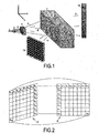
- Fig.1 1 is a schematic view of an article inspection device according to an embodiment of the present invention.
- the article inspection device mainly comprises an x-ray machine, a collimation unit 4, a transmission detector array 10 and a scattering detector array 12.
- the x-ray machine generates x-rays 3 by applying an electron beam 1 to bombard an electron target 2.
- the collimation unit 4 forms or shapes the x-rays 3 generated by the x-ray machine into a sector beam 5, and projects x-rays 6 of the sector beam 5 to an article 7.
- the sector beam 5 will transmit through the article 7 along a transmission cross section 8.
- the transmission detector array 10 is provided at an opposite side to the x-ray machine for detecting the x-rays 9 transmitting through the article 7 so as to form a two-dimensional image of the article 7.
- the scattering detector array 12 is provided at an opposite side to the transmission detector array 10 for detecting scattering photons 11 from the article 7 so as to form a three-dimensional image of the article7.
- the x-ray machine, the collimation unit 4 and the transmission detector array 10 each may be a conventional one that has been applied in a traditional x-ray imaging device.
- the x-ray machine, the collimation unit 4 and the transmission detector array 10 each may be a conventional one that has been applied in a traditional x-ray imaging device.
- the x-ray machine, the collimation unit 4 and the transmission detector array 10 each may be a conventional one that has been applied in a traditional x-ray imaging device.
- the x-ray machine, the collimation unit 4 and the transmission detector array 10 each may be a conventional one that has been applied in a traditional x-ray imaging device.
- the electron beam 1 of the x-ray machine should have enough energy to excite the electron target 2 after the electron target 2 is bombarded by the electron beam I to generate the x-rays 3 having energy enough to produce an pair production effect, for example, the electron beam 1 of the x-ray machine may have energy of more than 1.022MeV.
- the electron target 2 may be a composite target composed of wolfram and gold, or may be any one of conventional targets that can be adapted to the present invention.
- the x-rays 6 of the sector beam 5 transmit through the transmission cross section 8 of the article 7, the x-rays 6 of the sector beam 5 are attenuated because the photoelectric effect, the Compton effect, the pair production effect and the Rayleigh scattering effect occur.
- the scattering detector array 12 is provided at the same side of the article 7 as the x-ray machine, but the scattering detector array 12 may be provided at an opposite side of the article 7 to the x-ray machine.
- Fig.2 shows a corresponding relation between each of sub-regions of a transmission cross section of the article and each of the scattering detector modules.
- the scattering detector array 12 comprises sixty-four scattering detector modules arranged in a matrix of 8-rows and 8-columns, and all the scattering detector modules are exactly the same as one another.
- the sixty-four scattering detector modules arranged in the matrix of 8-rows and 8-columns comprises:
- the transmission cross section 8 of the article 7 is divided into sixty-four sub-regions arranged in a matrix of 8-rows and 8-columns, and all the sub-regions are exactly the same as one another.
- the sixty-four sub-regions arranged in the matrix of 8-rows and 8-columns comprises:
- each of the sub-regions of the transmission cross section 8 corresponds to each of the scattering detector modules of the scattering detector array 12.
- the sub-region A11 corresponds to the scattering detector module B 11;
- the sub-region A81 corresponds to the scattering detector module B81;
- the sub-region A88 corresponds to the scattering detector module B88.
- each of the scattering detector modules can only detect scattering photons from the corresponding one sub-region of the transmission cross section.
- the scattering detector array 12 each may comprise a plurality of same scattering detector modules arranged in a matrix of i-rows and j-columns, such as four same scattering detector modules arranged in a matrix of 2-rows and 2-columns, six same scattering detector modules arranged in a matrix of 2-rows and 3-columns, six same scattering detector modules arranged in a matrix of 3-rows and 2-columns, nine same scattering detector modules arranged in a matrix of 3-rows and 3-columns, twelve same scattering detector modules arranged in a matrix of 3-rows and 4-columns, and so on.
- four same scattering detector modules arranged in a matrix of 2-rows and 2-columns such as four same scattering detector modules arranged in a matrix of 2-rows and 2-columns, six same scattering detector modules arranged in a matrix of 2-rows and 3-columns, six same scattering detector modules arranged in a matrix of 3-rows and 2-column
- 'i' may be a positive integer equal to or greater than 2
- 'j' may be a positive integer equal to or greater than 2.
- the transmission cross section 8 may be divided into a plurality of same sub-regions arranged in a matrix of i-rows and j-columns.
- the resolution of the three-dimensional image formed by the article inspection device is proportional to parameters 'i' and 'j'. That is, when the parameters 'i' and 'j' become larger, the resolution of the three-dimensional image becomes higher. But the parameters 'i' and 'j' can not be too large, otherwise it makes the cost of the article inspection device very high.
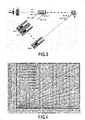
- Fig.3 is a cross section view along a plane perpendicular to Z-axis shown in Fig.1 .
- Fig.3 is a cross section view along a plane perpendicular to Z-axis shown in Fig.1 .
- the photoelectric effect In the photoelectric effect, photons are absorbed and their energy is converted into the energy of photoelectrons and characteristic x-rays. Generally, the photoelectrons can not be detected by the scattering detector modules, and the characteristic x-rays do not have enough energy to pass through the article and thus can not be detected by the scattering detector modules. But because of bremsstrahlung effect, the photoelectrons may be converted into x-rays having high energy and thus can be detected by the scattering detector modules. However, the present invention takes no interest in x-rays entering the scattering detector modules at all.
- the Compton-effect scattering photons A11_1 may enter a scattering detector of a scattering detector module B11.
- the scattering detector module B11 is designed and arranged so that only the Compton-effect scattering photons A11_1 from the sub-region A 11 corresponding to the scattering detector module B11 can enter the scattering detector module B 11.
- any one of other scattering detector modules B12-B18 is also designed and arranged to only receive the Compton-effect scattering photons from one sub-region corresponding to it.
- the scattering detector module B 12 can only receive the Compton-effect scattering photons A12_1 from the sub-region A 12 ...
- the scattering detector module B 18 can only receive the Compton-effect scattering photons A18_1 from the sub-region A18.
- the Compton scattering cross section is proportional to the atomic number when the energy of the incident x-rays 6 is constant. Therefore, in case respective sub-regions of the article have a same atomic density, the larger is the atomic number of one sub-region of the article, the larger is the Compton-effect scattering photon count detected by a scattering detector module corresponding to the one sub-region.
- the pair production effect may occur.
- flight in a solid of positron produced by the pair production effect is in the order of millimeter, each positron is annihilated and finally becomes two gamma photons each having energy of 511KeV, , the position where the two gamma photons are produced is in the sub-region A11.
- the scattering detector module B11 is designed and arranged so that only the pair production effect annihilation photons A11_2 from a sub-region A11 corresponding to the scattering detector module B I I can enter the scattering detector module B11.
- any one of the other scattering detector modules B12-B18 is also designed and arranged to only receive the pair production effect annihilation photons from one sub-region corresponding to it.
- the scattering detector module B12 can only receive the pair production effect annihilation photons A 12_2 from the sub-region A 12 ...
- the scattering detector module B18 can only receive the pair production effect annihilation photons A18_2 from the sub-region A 18.
- the pair production effect cross section is proportional to the second power of the atomic number. Therefore, in case respective sub-regions of the article have a same atomic density, the larger is the atomic number of one sub-region of the article, the larger is the pair production effect annihilation photon count detected by a scattering detector module corresponding to the one sub-region.
- the Rayleigh scattering effect can be omitted because Rayleigh scattering cross section is very small.
- the scattering detector array 12 takes interest in only the Compton scattering effect and the pair production effect.
- the Compton-effect scattering photon count and the pair production effect annihilation photon count are proportional to the first power and the second power of the atomic number, respectively. Therefore, the ratio of the pair production effect annihilation photon count detected by scattering detector array 12 to the Compton-effect scattering photon count detected by scattering detector array 12 is proportional to the first power of the atomic number. Accordingly, the atomic number information of respective sub-regions of the article can be obtained by the ratio of the pair production effect annihilation photon count to the Compton-effect scattering photon count.
- Fig.4 shows a relation between the ratio of the pair production effect annihilation photon count to the Compton-effect scattering photon count and the atomic number when incident x-rays 6 have different energies.
- the transmission cross section 8 of the article 7 is divided into a plurality of same sub-regions arranged in a matrix of i-rows and j-columns, and the scattering detector array 12 each correspondingly comprises a plurality of same scattering detector modules arranged in a matrix of i-rows and j-columns.
- the atomic numbers at all sub-regions, arranged in a matrix of i-rows and j-columns, of the transmission cross section 8 can be obtained by the detection information from the scattering detector modules, arranged in a matrix of i-rows and j-columns, of the scattering detector array 12.
- the atomic numbers at every sub-region of every transmission cross section 8 of the article can be obtained, and then a three-dimensional image of the whole article can be formed according to the atomic numbers at every sub-region of every transmission cross section 8 of the article.
- Fig.5 is a schematic structure view of each of scattering detector modules of the scattering detector array.
- each of the scattering detector modules of the scattering detector array 12 is exactly the same as one another, herein will only describe the scattering detector module B11 corresponding to the sub-region A11, as shown in Fig.5 .
- the scattering detector module B11 comprises a detector B11_1 and a collimator B11_2.
- the collimator B11_2 is configured to permit only the pair production effect annihilation photons A11_2 and the Compton effect scattered photons A11_1 from the sub-region A11 corresponding to the collimator B11_2 to enter the detector B11_1, that is, the collimator B11_2 is configured to substantially absorb the pair production effect annihilation photons and the Compton effect scattered photons from other sub-regions not corresponding to the collimator B11_2.
- the detector B11_1 may be a type of detector with a high energy resolution and a quick time response characteristic.
- the detector B11_1 may be a plastic scintillator detector or a liquid scintillator detector.
- the plastic scintillator detector and the liquid scintillator detector both have a quick time response characteristic and can detect the gamma photons within nanoseconds.
- the detector B11_1 may be a LaBr 3 (Ce) detector or a LaCl 3 (Ce) detector.
- the LaBr 3 (Ce) detector and the LaCl 3 (Ce) detector both have a high energy resolution and a quick time response characteristic.
- the detector B11_1 may be an HPGe detector.
- the HPGe detector has an excellent energy resolution, but has a poor time response characteristic.
- the detector B11_1 may be a CdZnTe detector.
- the CdZnTe detector also has an excellent energy resolution, but has a poor time response characteristic and its price is very high.
- the collimator B 11_2 may be made of lead, steel or copper. In this way, the collimator B 11_2 may effectively absorb the pair production effect annihilation photons and the Compton effect scattered photons from other sub-regions not corresponding to it, and permits only the pair production effect annihilation photons and the Compton effect scattered photons from the sub-region A11 corresponding to it to enter its detector.
- the scattering detector module B I 1 further comprises a shield B 11_3 for preventing the pair production effect annihilation photons A11_2 and the Compton effect scattered photons A11_1 from sub-regions not corresponding to the scattering detector module B11 from entering the detector B11_1, and particularly, preventing various transmitting or scattering x-rays from the electron target 2 from entering the detector B11_1.
- the shield B11_3 may be made of lead, steel or copper, or other suitable material.
- the scattering detector module B I 1 further comprises a hardenite B 11_4 for decreasing the intensity of the pair production effect annihilation photons A11_2 and the Compton effect scattered photons A11_1 from the sub-region A11 corresponding to the scattering detector module B11 so as to decrease the intensity of the pair production effect annihilation photons A11_2 and the Compton effect scattered photons A11_1 entering the detector B11_1. Otherwise, the detector B11_1 may be in an abnormal operation state because the counting rate is too high.
- the hardenite B11_4 may be made of lead, steel or copper, or other suitable material.
- the detector B11_1 is located in a collimation slit of the collimator B11_2.
- the shield B11_3 is disposed at one side of the collimator B11_2 opposite to the hardenite B11_4 and seals an opening of the collimation slit at the one side.
- the hardenite B11_4 is disposed at the other side of the collimator B11_2, and seals the other opening of the collimation slit at the other side.
- the shield B11_3 and the collimator B11_2 are formed into a piece. But please be noted that the shield B11_3 and the collimator B 11_2 may be formed into two individual pieces.
- Fig.6 shows energy spectrums of the pair production effect annihilation photons and the Compton effect scattered photons entering the scattering detector array 12.
- the pair production effect annihilation photons have energy of 511 KeV.
- the energy of the Compton-effect scattering photons is mainly related to two parameters: Compton scattering angle ⁇ (please see Fig.3 ) and the energy hv of the incident x-rays 6. Because the energy spectrum of the incident x-rays 6 is a continuous energy spectrum, the energy spectrum of the Compton-effect scattering photons is also a continuous energy spectrum, as shown in Fig.6 .
Description
- The present invention relates to an article inspection device for inspecting dangerous goods, such as explosive materials, chemicals, biological weapons, nuclear materials and drugs, hidden in an article. In addition, the present invention also relates to an article inspection method.
- In order to detect dangerous goods, such as explosives, chemicals, biological weapons, nuclear materials and drugs, hidden in a ship container or in an air container, many technical solutions have been proposed, for example, two popular solutions of which are an x-ray inspection technology and a neutron inspection technology, which are simply described as follows:
- The conventional x-ray transmission solution includes a monoenergetic x-ray transmission method and a polyenergetic x-ray transmission method. In each of the methods attenuation information of x-rays transmitting through an article to be inspected is firstly detected by use of a transmission detector array, and then a two-dimensional image of the article is formed based on the attenuation information. The two-dimensional image is representative of mass thickness information of the article along the x-rays transmission path. In this way, by analyzing the shape of the two-dimensional image, an operator can determine whether the article contains dangerous goods therein. However, the x-ray transmission solution can only obtain an integration of attenuation ability of the article to be inspected along the x-rays transmission path, thereby it can not discriminate a thinner article having a high atomic number and a high atomic density from a thicker article having a low atomic number and a low atomic density. Therefore, it can not detect nuclear materials hidden in the article with enough accuracy.
- The conventional nuclear resonance fluorescence solution comprises firstly adopting x-rays to excite an atomic nucleus, and then detecting gamma photons generated by the atomic nucleus after being excited. In this way, the conventional nuclear resonance fluorescence solution can obtain "fingerprint information" of the atomic nucleus of interest. However, the x-rays that can generate resonance absorption have a very small energy spectrum width, which causes the article to generate a few number of resonance fluorescence but a great number of scattering photons after being irradiated by the x-rays, thereby the conventional nuclear resonance fluorescence solution is disadvantageously interfered by background information from the scattering photons, and has a poor detection sensitivity. For the purpose of improving the detection sensitivity, another new method of using an adjustable monoenergetic x-ray source is recently proposed, but it needs an electron accelerator with energy of more than 100MeV.
- The conventional neutron transmission solution is similar with the above conventional x-ray transmission solution. The neutron is sensitive to materials having a low atomic number, particularly hydrogen, but usually is not sensitive to those having a high atomic number. Thereby, compared with the above conventional x-ray transmission solution, the conventional neutron transmission solution is good at detecting materials containing a great deal of hydrogen. However, the neutron transmission solution also can only obtain integration information along the neutron transmission path, thereby it can not discriminate chemical elements of materials arranged at various spatial locations. Therefore, it can not detect nuclear materials hidden in the article, either.
- The elements concentration analysis solution can discriminate different elements based on gamma rays induced by reaction of neutrons with nuclear. Furthermore, another elements concentration analysis solution that can discriminate different elements arranged in three-dimensional space is recently proposed, wherein a three-dimensional space element image of an article to be inspected, such as a container or a vehicle, can be formed in a 5cm × 5cm × 5cm spatial resolution. However, the elements concentration analysis solution can only be adapted to nuclides having a large neutron reaction cross section, such as Nitrogen, Carbon, Oxygen and Hydrogen, and can not be adapted to nuclear elements having a small neutron reaction cross section. In addition, in the elements concentration analysis solution, it needs to detect energy spectra of γ-rays with high temporal and energy resolution. Because of the very complicated γ-rays spectra induced by the neutron reactions with matter, it is very hard to interpret spectra and extract elements concentration information. Also, the neutron generator should produce neutron pulse of nanosecond width, this is very difficult.
- A prior art article inspection device is known from
US 5940468 . - In addition to the above conventional inspection methods, there are a few of other methods, for example, a nuclear quadrupole resonance (NQR) solution. The NQR method is sensitive to a molecule and can get "fingerprint" information of the molecule. But a condition must be satisfied that the molecule must contain a nucleus whose quadrupole moment is not zero and an electric field gradient in which the atomic nucleus is located must be rather large. However, only a few of materials can satisfy with the above condition. Furthermore, NQR does not work well if the inspected object is electromagnetically shielded.
- The present invention has been made to overcome or alleviate at least one aspect of the above mentioned disadvantages.
- Accordingly, it is an object of the present invention to provide an article inspection device and an inspection method that can easily form a three-dimensional image for the article.
- According to an aspect of the present invention, there is provided an article inspection , device according to
claim 1. - According to the present invention, each of the scattering detector modules comprises:
- a detector; and
- a collimator for absorbing the pair production effect annihilation photons and the Compton-effect scattering photons from other sub-regions not corresponding to the collimator to permit only the pair production effect annihilation photons and the Compton-effect scattering photons from the one sub-region corresponding to the collimator to enter the detector.
- In an exemplary embodiment according to the present invention, the detector is a LaBr3(Ce) detector, a LaCl3(Ce) detector, a HPGe detector or a CdZnTe detector.
- In an exemplary embodiment according to the present invention, the collimator is made of lead, steel or copper.
- In an exemplary embodiment according to the present invention, each of the scattering detector modules further comprises: a shield for preventing the pair production effect annihilation photons and the Compton-effect scattering photons, from sub-regions not corresponding to the collimator of the scattering detector module, from entering the detector. In an exemplary embodiment according to the present invention, the shield is made of lead, steel or copper.
- In an exemplary embodiment according to the present invention, each of the scattering detector modules further comprises: a hardenite for decreasing the intensity of the pair production effect annihilation photons and the Compton-effect scattering photons from the one sub-region corresponding to the collimator of the scattering detector module. In an exemplary embodiment according to the present invention, the hardenite is made of lead, steel or copper.
- In an exemplary embodiment according to the present invention, the detector is located in a collimation slit of the collimator; the shield is disposed at one side of the collimator opposite to the article, and seals an opening of the collimation slit at the one side; and the hardenite is disposed at the other side of the collimator facing the article, and seals the other opening of the collimation slit at the other side.
- In an exemplary embodiment according to the present invention, the shield and the collimator are formed into a piece.
- In an exemplary embodiment according to the present invention, the x-ray machine is a monoenergetic x-ray machine or a polyenergetic x-ray machine.
- In an exemplary embodiment according to the present invention, the x-rays generated by the x-ray machine have energy of more than 1.022MeV.
- According to another aspect of the present invention, there is provided a method for inspecting an article by using article inspection device according to the above, comprising:
- detecting an attenuation information of x-rays transmitting through an article by use of a transmission detector array, and detecting pair production effect annihilation photon count and Compton-effect scattering photon count during the x-rays transmitting through the article by use of scattering detector array; and
- forming a two-dimensional image of the article based on the detected attenuation information, and forming a three-dimensional image of the article based on a ratio of the pair production effect annihilation photon count to the Compton-effect scattering photon count.
- These and/or other aspects and advantages of the invention will become apparent and more readily appreciated from the following description of the embodiments, taken in conjunction with the accompanying drawings, in which:
-
Fig. 1 is a schematic view of an article inspection device according to an embodiment of the present invention; -
Fig.2 is a view showing a corresponding relation between each of sub-regions of a transmission cross section of the article to be inspected and each of the scattering detector modules of the scattering detector array; -
Fig.3 is a cross section view along a plane perpendicular to Z-axis shown inFig.1 ; -
Fig.4 shows a relation between an atomic number and a ratio of the pair production effect annihilation photon count to the Compton-effect scattering photon count; -
Fig.5 is a schematic structure view of each of scattering detector modules of the scattering detector array; and -
Fig.6 shows energy spectrums of the pair production effect annihilation photons and the Compton-effect scattering photons entering the scattering detector arrays. - Exemplary embodiments of the present disclosure will be described hereinafter in detail with reference to the attached drawings, wherein the like reference numerals refer to the like elements.
-
Fig.1 1 is a schematic view of an article inspection device according to an embodiment of the present invention. - As shown in
Fig.1 , in an exemplary embodiment of the present invention, the article inspection device mainly comprises an x-ray machine, acollimation unit 4, atransmission detector array 10 and ascattering detector array 12. - In this exemplary embodiment, referring to
Fig.1 , the x-ray machine generatesx-rays 3 by applying anelectron beam 1 to bombard anelectron target 2. Thecollimation unit 4 forms or shapes thex-rays 3 generated by the x-ray machine into asector beam 5, andprojects x-rays 6 of thesector beam 5 to an article 7. Thesector beam 5 will transmit through the article 7 along atransmission cross section 8. - Also referring to
Fig.1 , thetransmission detector array 10 is provided at an opposite side to the x-ray machine for detecting thex-rays 9 transmitting through the article 7 so as to form a two-dimensional image of the article 7. Thescattering detector array 12 is provided at an opposite side to thetransmission detector array 10 for detectingscattering photons 11 from the article 7 so as to form a three-dimensional image of the article7. - In an exemplary embodiment of the present invention, the x-ray machine, the
collimation unit 4 and thetransmission detector array 10 each may be a conventional one that has been applied in a traditional x-ray imaging device. For clarity, herein is omitted their further detailed description. - In an exemplary embodiment of the present invention, the
electron beam 1 of the x-ray machine should have enough energy to excite theelectron target 2 after theelectron target 2 is bombarded by the electron beam I to generate thex-rays 3 having energy enough to produce an pair production effect, for example, theelectron beam 1 of the x-ray machine may have energy of more than 1.022MeV. In an exemplary embodiment of the present invention, theelectron target 2 may be a composite target composed of wolfram and gold, or may be any one of conventional targets that can be adapted to the present invention. - As shown in
Fig. 1 , duringx-rays 6 of thesector beam 5 transmit through thetransmission cross section 8 of the article 7, thex-rays 6 of thesector beam 5 are attenuated because the photoelectric effect, the Compton effect, the pair production effect and the Rayleigh scattering effect occur. - In an exemplary embodiment of the present invention, referring to
Fig.1 , thescattering detector array 12 is provided at the same side of the article 7 as the x-ray machine, but thescattering detector array 12 may be provided at an opposite side of the article 7 to the x-ray machine. -
Fig.2 shows a corresponding relation between each of sub-regions of a transmission cross section of the article and each of the scattering detector modules. - Please refer to
Fig. 1 and Fig.2 , in an exemplary embodiment of the present invention, thescattering detector array 12 comprises sixty-four scattering detector modules arranged in a matrix of 8-rows and 8-columns, and all the scattering detector modules are exactly the same as one another. As shown inFig.2 , the sixty-four scattering detector modules arranged in the matrix of 8-rows and 8-columns comprises: - Eight scattering detector modules B11-B18 in a first line of the
scattering detector array 12; - Eight scattering detector modules B21-B28 in a second line of the
scattering detector array 12; - Eight scattering detector modules B31-B38 in a third line of the
scattering detector array 12; - Eight scattering detector modules B41-B48 in a fourth line of the
scattering detector array 12; - Eight scattering detector modules B51-B58 in a fifth line of the
scattering detector array 12; - Eight scattering detector modules B61-B68 in a sixth line of the
scattering detector array 12; - Eight scattering detector modules B71-B78 in a seventh line of the
scattering detector array 12; and - Eight scattering detector modules B81-B88 in an eighth line of the
scattering detector array 12. - Similarly, please continue refer to
Fig. 1 and Fig.2 , thetransmission cross section 8 of the article 7 is divided into sixty-four sub-regions arranged in a matrix of 8-rows and 8-columns, and all the sub-regions are exactly the same as one another. As shown inFig.2 , the sixty-four sub-regions arranged in the matrix of 8-rows and 8-columns comprises: - Eight sub-regions A11-A18 in a first line of the
transmission cross section 8; - Eight sub-regions A21-A28 in a second line of the
transmission cross section 8; - Eight sub-regions A31-A38 in a third line of the
transmission cross section 8; - Eight sub-regions A41-A48 in a fourth line of the
transmission cross section 8; - Eight sub-regions A51-A58 in a fifth line of the
transmission cross section 8; - Eight sub-regions A61-A68 in a sixth line of the
transmission cross section 8; - Eight sub-regions A71-A78 in a seventh line of the
transmission cross section 8; and - Eight sub-regions A81-A88 in an eighth line of the
transmission cross section 8. - As shown in
Fig.2 , in an exemplary embodiment of the present invention, each of the sub-regions of thetransmission cross section 8 corresponds to each of the scattering detector modules of thescattering detector array 12. For example, the sub-region A11 corresponds to the scatteringdetector module B 11; the sub-region A81 corresponds to the scattering detector module B81; the sub-region A88 corresponds to the scattering detector module B88. Thereby, in the exemplary embodiment of the present invention, each of the scattering detector modules can only detect scattering photons from the corresponding one sub-region of the transmission cross section. - Although it is not shown, in an exemplary embodiment of the present invention, the
scattering detector array 12 each may comprise a plurality of same scattering detector modules arranged in a matrix of i-rows and j-columns, such as four same scattering detector modules arranged in a matrix of 2-rows and 2-columns, six same scattering detector modules arranged in a matrix of 2-rows and 3-columns, six same scattering detector modules arranged in a matrix of 3-rows and 2-columns, nine same scattering detector modules arranged in a matrix of 3-rows and 3-columns, twelve same scattering detector modules arranged in a matrix of 3-rows and 4-columns, and so on. That is, in the exemplary embodiment of the present invention, 'i' may be a positive integer equal to or greater than 2, and 'j' may be a positive integer equal to or greater than 2. Similarly, thetransmission cross section 8 may be divided into a plurality of same sub-regions arranged in a matrix of i-rows and j-columns. - In the exemplary embodiment of the present invention, the resolution of the three-dimensional image formed by the article inspection device is proportional to parameters 'i' and 'j'. That is, when the parameters 'i' and 'j' become larger, the resolution of the three-dimensional image becomes higher. But the parameters 'i' and 'j' can not be too large, otherwise it makes the cost of the article inspection device very high.
-
Fig.3 is a cross section view along a plane perpendicular to Z-axis shown inFig.1 . Next the procedure of detecting scattering photons generated at respective sub-regions by using respective scattering detector modules will be described with respect toFig.3 . - As above description, during the
x-rays 6 of thesector beam 5 transmit through thetransmission cross section 8 of the article 7, the photoelectric effect, the Compton effect, the pair production effect and the Rayleigh scattering effect. The four effects will be simply described as follows. - In the photoelectric effect, photons are absorbed and their energy is converted into the energy of photoelectrons and characteristic x-rays. Generally, the photoelectrons can not be detected by the scattering detector modules, and the characteristic x-rays do not have enough energy to pass through the article and thus can not be detected by the scattering detector modules. But because of bremsstrahlung effect, the photoelectrons may be converted into x-rays having high energy and thus can be detected by the scattering detector modules. However, the present invention takes no interest in x-rays entering the scattering detector modules at all.
- As shown in
Fig.3 , whenincident x-rays 6 react with respective sub-regions of thetransmission cross section 8 of the article 7, the Compton Effect may occur. - Please refer to
Fig.3 , when theincident x-rays 6 react with the sub-region A11, the Compton-effect scattering photons A11_1 may enter a scattering detector of a scattering detector module B11. In an exemplary embodiment of the present invention, the scattering detector module B11 is designed and arranged so that only the Compton-effect scattering photons A11_1 from thesub-region A 11 corresponding to the scattering detector module B11 can enter the scatteringdetector module B 11. Similarly, any one of other scattering detector modules B12-B18 is also designed and arranged to only receive the Compton-effect scattering photons from one sub-region corresponding to it. For example, as shown inFig.3 , the scatteringdetector module B 12 can only receive the Compton-effect scattering photons A12_1 from thesub-region A 12 ..., the scattering detector module B 18 can only receive the Compton-effect scattering photons A18_1 from the sub-region A18. - It is well known that the Compton scattering cross section is proportional to the atomic number when the energy of the
incident x-rays 6 is constant. Therefore, in case respective sub-regions of the article have a same atomic density, the larger is the atomic number of one sub-region of the article, the larger is the Compton-effect scattering photon count detected by a scattering detector module corresponding to the one sub-region. - As shown in
Fig.3 , when theincident x-rays 6 react with respective sub-regions of thetransmission cross section 8 of the article 7, the pair production effect may occur. In the pair production effect, because flight in a solid of positron produced by the pair production effect is in the order of millimeter, each positron is annihilated and finally becomes two gamma photons each having energy of 511KeV, , the position where the two gamma photons are produced is in the sub-region A11. - Please refer to
Fig.3 , in an exemplary embodiment of the present invention, the scattering detector module B11 is designed and arranged so that only the pair production effect annihilation photons A11_2 from a sub-region A11 corresponding to the scattering detector module B I I can enter the scattering detector module B11. Similarly, any one of the other scattering detector modules B12-B18 is also designed and arranged to only receive the pair production effect annihilation photons from one sub-region corresponding to it. For example, as shown inFig.3 , the scattering detector module B12 can only receive the pair production effect annihilation photons A 12_2 from thesub-region A 12 ..., the scattering detector module B18 can only receive the pair production effect annihilation photons A18_2 from the sub-region A 18. - It is well known that the pair production effect cross section is proportional to the second power of the atomic number. Therefore, in case respective sub-regions of the article have a same atomic density, the larger is the atomic number of one sub-region of the article, the larger is the pair production effect annihilation photon count detected by a scattering detector module corresponding to the one sub-region.
- When the
incident x-rays 6 have energy of more than 1.022MeV, the Rayleigh scattering effect can be omitted because Rayleigh scattering cross section is very small. - Among the above four scattering effects, the
scattering detector array 12 takes interest in only the Compton scattering effect and the pair production effect. As the above description, the Compton-effect scattering photon count and the pair production effect annihilation photon count are proportional to the first power and the second power of the atomic number, respectively. Therefore, the ratio of the pair production effect annihilation photon count detected by scatteringdetector array 12 to the Compton-effect scattering photon count detected by scatteringdetector array 12 is proportional to the first power of the atomic number. Accordingly, the atomic number information of respective sub-regions of the article can be obtained by the ratio of the pair production effect annihilation photon count to the Compton-effect scattering photon count. -
Fig.4 shows a relation between the ratio of the pair production effect annihilation photon count to the Compton-effect scattering photon count and the atomic number whenincident x-rays 6 have different energies. - Referring to
Fig.4 , there is an excellent linear relationship between the ratio of the pair production effect annihilation photon count to the Compton-effect scattering photon count and the atomic number. Therefore, the atomic number can be calculated by a following formula:
Wherein,
C_ pair is the pair production effect annihilation photon count;
C_ compton is the Compton-effect scattering photon count;
Zpc is the ratio of the pair production effect annihilation photon count to the Compton-effect scattering photon count;
Z is the atomic number. - In practice, because of some unavoidable errors, it is necessary to calibrate the relation between the ratio Zpc and the atomic number Z according to experiments
- As the above description, the
transmission cross section 8 of the article 7 is divided into a plurality of same sub-regions arranged in a matrix of i-rows and j-columns, and thescattering detector array 12 each correspondingly comprises a plurality of same scattering detector modules arranged in a matrix of i-rows and j-columns. Thereby, the atomic numbers at all sub-regions, arranged in a matrix of i-rows and j-columns, of thetransmission cross section 8 can be obtained by the detection information from the scattering detector modules, arranged in a matrix of i-rows and j-columns, of thescattering detector array 12. When the article is wholly scanned, the atomic numbers at every sub-region of everytransmission cross section 8 of the article can be obtained, and then a three-dimensional image of the whole article can be formed according to the atomic numbers at every sub-region of everytransmission cross section 8 of the article. -
Fig.5 is a schematic structure view of each of scattering detector modules of the scattering detector array. - In an exemplary embodiment of the present invention, since each of the scattering detector modules of the
scattering detector array 12 is exactly the same as one another, herein will only describe the scattering detector module B11 corresponding to the sub-region A11, as shown inFig.5 . - Please refer to
Fig.3 andFig.5 , the scattering detector module B11 comprises a detector B11_1 and a collimator B11_2. In the illustrated exemplary embodiment, the collimator B11_2 is configured to permit only the pair production effect annihilation photons A11_2 and the Compton effect scattered photons A11_1 from the sub-region A11 corresponding to the collimator B11_2 to enter the detector B11_1, that is, the collimator B11_2 is configured to substantially absorb the pair production effect annihilation photons and the Compton effect scattered photons from other sub-regions not corresponding to the collimator B11_2. - In an exemplary embodiment of the present invention, the detector B11_1 may be a type of detector with a high energy resolution and a quick time response characteristic.
- In an exemplary embodiment of the present invention, the detector B11_1 may be a plastic scintillator detector or a liquid scintillator detector. The plastic scintillator detector and the liquid scintillator detector both have a quick time response characteristic and can detect the gamma photons within nanoseconds.
- In an exemplary embodiment of the present invention, the detector B11_1 may be a LaBr3(Ce) detector or a LaCl3(Ce) detector. The LaBr3(Ce) detector and the LaCl3(Ce) detector both have a high energy resolution and a quick time response characteristic.
- In an exemplary embodiment of the present invention, the detector B11_1 may be an HPGe detector. The HPGe detector has an excellent energy resolution, but has a poor time response characteristic.
- In an exemplary embodiment of the present invention, the detector B11_1 may be a CdZnTe detector. The CdZnTe detector also has an excellent energy resolution, but has a poor time response characteristic and its price is very high.
- In an exemplary embodiment of the present invention, the collimator B 11_2 may be made of lead, steel or copper. In this way, the collimator B 11_2 may effectively absorb the pair production effect annihilation photons and the Compton effect scattered photons from other sub-regions not corresponding to it, and permits only the pair production effect annihilation photons and the Compton effect scattered photons from the sub-region A11 corresponding to it to enter its detector.
- In an exemplary embodiment of the present invention, as shown in
Fig.3 andFig.5 , the scatteringdetector module B I 1 further comprises a shield B 11_3 for preventing the pair production effect annihilation photons A11_2 and the Compton effect scattered photons A11_1 from sub-regions not corresponding to the scattering detector module B11 from entering the detector B11_1, and particularly, preventing various transmitting or scattering x-rays from theelectron target 2 from entering the detector B11_1. In an exemplary embodiment of the present invention, the shield B11_3 may be made of lead, steel or copper, or other suitable material. - In an exemplary embodiment of the present invention, as shown in
Fig.3 andFig.5 , the scatteringdetector module B I 1 further comprises a hardenite B 11_4 for decreasing the intensity of the pair production effect annihilation photons A11_2 and the Compton effect scattered photons A11_1 from the sub-region A11 corresponding to the scattering detector module B11 so as to decrease the intensity of the pair production effect annihilation photons A11_2 and the Compton effect scattered photons A11_1 entering the detector B11_1. Otherwise, the detector B11_1 may be in an abnormal operation state because the counting rate is too high. In an exemplary embodiment of the present invention, the hardenite B11_4 may be made of lead, steel or copper, or other suitable material. - Please continue refer to
Fig.5 , in an exemplary embodiment of the present invention, the detector B11_1 is located in a collimation slit of the collimator B11_2. The shield B11_3 is disposed at one side of the collimator B11_2 opposite to the hardenite B11_4 and seals an opening of the collimation slit at the one side. The hardenite B11_4 is disposed at the other side of the collimator B11_2, and seals the other opening of the collimation slit at the other side. - In an exemplary embodiment of the present invention, the shield B11_3 and the collimator B11_2 are formed into a piece. But please be noted that the shield B11_3 and the collimator B 11_2 may be formed into two individual pieces.
-
Fig.6 shows energy spectrums of the pair production effect annihilation photons and the Compton effect scattered photons entering thescattering detector array 12. - As shown in
Fig.6 , the pair production effect annihilation photons have energy of 511 KeV. - As a formula shown in
Fig.6 , the energy of the Compton-effect scattering photons is mainly related to two parameters: Compton scattering angle θ (please seeFig.3 ) and the energy hv of theincident x-rays 6. Because the energy spectrum of theincident x-rays 6 is a continuous energy spectrum, the energy spectrum of the Compton-effect scattering photons is also a continuous energy spectrum, as shown inFig.6 .
Claims (12)
- An article inspection device, comprising:a x-ray machine;a collimation unit (4) for shaping x-rays (3) generated by the x-ray machine into a sector beam (5) to project an article (7);a transmission detector array (10) for detecting the x-rays transmitting through the article so as to form a two-dimensional image of the article (7); anda scattering detector array (12) characterized in the scattering detector array (12) comprising a plurality of same scattering detector modules (Bi,j) arranged in a matrix of i-rows and j-columns,wherein a transmission cross section (8) of the article (7) transmitted by the x-rays is divided into a plurality of same sub-regions (Ai,j) arranged in a matrix of i-rows and j-columns,wherein the plurality of scattering detector modules (Bi,j) arranged in i-rows and j-columns correspond to the plurality of sub-regions arranged in i-rows and j-columns one by one for detecting pair production effect annihilation photons and Compton-effect scattering photons from the respective sub-regions produced by the x-rays,wherein obtaining atomic numbers of the respective sub-regions based on a ratio of the pair production effect annihilation photon count to the Compton-effect scattering photon count, so as to form a three-dimensional image of the article,wherein 'i' is a positive integer equal to or greater than 2, and 'j' is a positive integer equal to or greater than 2,wherein each of the scattering detector modules (B11) comprises:a detector (B11_1); anda collimator (B11_2) for absorbing the pair production effect annihilation photons and the Compton-effect scattering photons (A11_1) from other sub-regions not corresponding to the collimator to permit only the pair production effect annihilation photons and the Compton-effect scattering photons from the one sub-region corresponding to the collimator to enter the detector.
- The article inspection device according to claim 1, wherein the detector is a LaBr3(Ce) detector, a LaCl3(Ce) detector, a HPGe detector or a CdZnTe detector.
- The article inspection device according to claim 1, wherein the collimator is made of lead, steel or copper.
- The article inspection device according to claim 1, wherein each of the scattering detector modules (B11) further comprises:a shield (B11_3) for preventing the pair production effect annihilation photons and the Compton-effect scattering photons, from sub-regions not corresponding to the collimator of the scattering detector module, from entering the detector.
- The article inspection device according to claim 4, wherein the shield is made of lead, steel or copper.
- The article inspection device according to claim 4, wherein each of the scattering detector modules (B11) further comprises:a hardenite (B11_4) for decreasing the intensity of the pair production effect annihilation photons and the Compton-effect scattering photons from the one sub-region corresponding to the collimator of the scattering detector module.
- The article inspection device according to claim 6, wherein the hardenite is made of lead, steel or copper.
- The article inspection device according to claim 6, wherein
the detector is located in a collimation slit of the collimator;
the shield is disposed at one side of the collimator opposite to the article, and seals an opening of the collimation slit at the one side; and
the hardenite is disposed at the other side of the collimator facing the article, and seals the other opening of the collimation slit at the other side. - The article inspection device according to claim 8, wherein the shield and the collimator are formed into a piece.
- The article inspection device according to claim 1, wherein the x-ray machine is a monoenergetic x-ray machine or a polyenergetic x-ray machine.
- The article inspection device according to claim 1, wherein the x-rays generated by the x-ray machine have energy of more than 1.022MeV.
- A method for inspecting an article by using article inspection device according to any one of the preceding claims 1-11, comprising:detecting an attenuation information of x-rays transmitting through an article by use of a transmission detector array, and detecting pair production effect annihilation photon count and Compton-effect scattering photon count during the x-rays transmits through the article by use of scattering detector array; andforming a two-dimensional image of the article based on the detected attenuation information, and forming a three-dimensional image of the article based on a ratio of the pair production effect annihilation photon count to the Compton-effect scattering photon count.
Priority Applications (1)
| Application Number | Priority Date | Filing Date | Title |
|---|---|---|---|
| PL10854001T PL2589954T3 (en) | 2010-06-30 | 2010-12-28 | Articles detection device and detection method thereof |
Applications Claiming Priority (2)
| Application Number | Priority Date | Filing Date | Title |
|---|---|---|---|
| CN201010223292.7A CN102313752B (en) | 2010-06-30 | 2010-06-30 | Article detection equipment and method |
| PCT/CN2010/080369 WO2012000298A1 (en) | 2010-06-30 | 2010-12-28 | Articles detection device and detection method thereof |
Publications (3)
| Publication Number | Publication Date |
|---|---|
| EP2589954A1 EP2589954A1 (en) | 2013-05-08 |
| EP2589954A4 EP2589954A4 (en) | 2013-11-20 |
| EP2589954B1 true EP2589954B1 (en) | 2015-07-01 |
Family
ID=45401360
Family Applications (1)
| Application Number | Title | Priority Date | Filing Date |
|---|---|---|---|
| EP10854001.4A Active EP2589954B1 (en) | 2010-06-30 | 2010-12-28 | Articles detection device and detection method thereof |
Country Status (5)
| Country | Link |
|---|---|
| US (1) | US8406375B2 (en) |
| EP (1) | EP2589954B1 (en) |
| CN (1) | CN102313752B (en) |
| PL (1) | PL2589954T3 (en) |
| WO (1) | WO2012000298A1 (en) |
Families Citing this family (14)
| Publication number | Priority date | Publication date | Assignee | Title |
|---|---|---|---|---|
| CN103728324B (en) * | 2013-12-18 | 2016-08-17 | 中国原子能科学研究院 | A kind of nuclear fuel assembly nondestructive detection device for high-energy X-ray |
| CN104062308B (en) * | 2014-07-04 | 2017-02-15 | 天津三英精密仪器有限公司 | Rock nondestructive mineral composition detection method |
| CN105445290A (en) * | 2014-09-02 | 2016-03-30 | 同方威视技术股份有限公司 | Product quality online detection X-ray apparatus |
| CN104792805B (en) * | 2015-04-16 | 2017-09-12 | 中国原子能科学研究院 | A kind of transmission detectors and interpolated data computational methods |
| CN106353828B (en) * | 2015-07-22 | 2018-09-21 | 清华大学 | The method and apparatus that checked property body weight is estimated in safe examination system |
| EP3371774B1 (en) * | 2015-11-05 | 2021-06-30 | Volpara Health Technologies Limited | Method for quantification of images |
| US9528952B1 (en) * | 2016-05-17 | 2016-12-27 | Westinghouse Electric Company Llc | Pulsed neutron generated prompt gamma emission measurement system for surface defect detection and analysis |
| BR112018074796B1 (en) * | 2016-05-30 | 2023-03-28 | Southern Innovation International Pty Ltd | MATERIAL CHARACTERIZATION SYSTEM AND METHOD |
| GB2555564B (en) * | 2016-07-28 | 2020-09-09 | Smiths Heimann Sas | Scatter imaging |
| GB2552535B (en) * | 2016-07-28 | 2020-09-09 | Smiths Heimann Sas | Detection of scatter radiation |
| CN110199209B (en) | 2016-07-28 | 2021-07-30 | 德国史密斯海曼简化股份公司 | Scatter imaging |
| EP3435325A1 (en) * | 2017-07-26 | 2019-01-30 | Koninklijke Philips N.V. | Scatter correction for dark field imaging |
| WO2020093232A1 (en) * | 2018-11-06 | 2020-05-14 | Shenzhen Xpectvision Technology Co., Ltd. | A Backscatter X-ray System |
| CN117571543B (en) * | 2024-01-16 | 2024-04-09 | 清华大学 | Method and system for online measurement of true density of bulk material by utilizing X/gamma rays |
Family Cites Families (13)
| Publication number | Priority date | Publication date | Assignee | Title |
|---|---|---|---|---|
| SU707403A1 (en) * | 1978-05-30 | 1981-06-15 | Научно-Исследовательский Институт Ядерной Физикиэлектроники И Автоматики При Tomckom Орденаоктябрьской Революции И Ордена Трудового Ккрасного Знамени Политехническом Институте Им.C.M.Кирова | Method of density radiational measuring |
| FR2442042A1 (en) * | 1978-11-27 | 1980-06-20 | Labo Electronique Physique | METHOD AND APPARATUS FOR TOMOGRAPHIC EXAMINATION BY EXPLORATION OF X-RAY OR GAMMA MEDIA |
| WO1992003722A1 (en) * | 1990-08-15 | 1992-03-05 | Massachusetts Institute Of Technology | Detection of explosives and other materials using resonance fluorescence, resonance absorption, and other electromagnetic processes with bremsstrahlung radiation |
| WO1998020366A1 (en) * | 1996-11-08 | 1998-05-14 | American Science And Engineering, Inc. | Coded aperture x-ray imaging system |
| CA2348150C (en) * | 2000-05-25 | 2007-03-13 | Esam M.A. Hussein | Non-rotating x-ray system for three-dimensional, three-parameter imaging |
| CN1164928C (en) * | 2001-09-21 | 2004-09-01 | 清华大学 | Detecting method and equipment for X-or gamma-radiation imaging |
| CN1179207C (en) * | 2001-11-27 | 2004-12-08 | 丹东东方测控技术有限公司 | Method and system for in-situ testing grade of big ore block by electron-air shielding radiation effect |
| US7078699B2 (en) * | 2002-10-04 | 2006-07-18 | Varian Medical Systems Technologies, Inc. | Imaging apparatus and method with event sensitive photon detection |
| SE0302900L (en) | 2003-11-03 | 2005-05-04 | Xcounter Ab | Coherent scattering imaging |
| DE102005024892B3 (en) * | 2005-05-31 | 2006-09-28 | Yxlon International Security Gmbh | Radiography and computer tomography method in which a region of interest is first determined using a transmission detector and then examined in detail using a coherent scatter detector |
| US20090168958A1 (en) * | 2008-01-02 | 2009-07-02 | Cristina Francesca Cozzini | Apparatus and method for identifying components in a container |
| CN101629917B (en) * | 2008-07-16 | 2011-09-14 | 清华大学 | Method and device for measuring effective atomic number of substance |
| US8588370B2 (en) * | 2010-06-30 | 2013-11-19 | Tsinghua University | Article inspection device and inspection method |
-
2010
- 2010-06-30 CN CN201010223292.7A patent/CN102313752B/en active Active
- 2010-12-28 WO PCT/CN2010/080369 patent/WO2012000298A1/en active Application Filing
- 2010-12-28 US US13/142,712 patent/US8406375B2/en active Active
- 2010-12-28 EP EP10854001.4A patent/EP2589954B1/en active Active
- 2010-12-28 PL PL10854001T patent/PL2589954T3/en unknown
Also Published As
| Publication number | Publication date |
|---|---|
| EP2589954A1 (en) | 2013-05-08 |
| CN102313752B (en) | 2014-07-23 |
| EP2589954A4 (en) | 2013-11-20 |
| CN102313752A (en) | 2012-01-11 |
| US8406375B2 (en) | 2013-03-26 |
| WO2012000298A1 (en) | 2012-01-05 |
| US20120207271A1 (en) | 2012-08-16 |
| PL2589954T3 (en) | 2016-04-29 |
Similar Documents
| Publication | Publication Date | Title |
|---|---|---|
| EP2589954B1 (en) | Articles detection device and detection method thereof | |
| EP2589955B1 (en) | Articles detecting device and detecting method thereof | |
| US9268043B2 (en) | Radiation-monitoring system with correlated hodoscopes | |
| AU2008267661B2 (en) | Method and system for contraband detection using photoneutrons and x-rays | |
| JP4995905B2 (en) | Detector assembly and method for detecting radiation with angular resolution | |
| Buffler et al. | Detecting contraband using neutrons: challenges and future directions | |
| US20050195931A1 (en) | Binocular method and apparatus for stoichiometric analysis and imaging using subatomic particle activation | |
| Harding et al. | X-ray diffraction imaging with the Multiple Inverse Fan Beam topology: Principles, performance and potential for security screening | |
| US6693281B2 (en) | Fast neutron resonance radiography for elemental mapping | |
| US8588370B2 (en) | Article inspection device and inspection method | |
| JP2015121547A (en) | Dual isotope notch observer for isotope identification, assay and imaging with mono-energetic gamma-ray sources | |
| JP3827224B2 (en) | Luggage inspection device | |
| LaGraffe | Nuclear security science | |
| Perot et al. | The EURITRACK project: development of a tagged neutron inspection system for cargo containers | |
| Martz et al. | Summary of technologies for national security needs | |
| EP2074413B1 (en) | Method for detecting nitrogenous materials via gamma-resonance absorption (gra) | |
| Cárdenas et al. | Comparison of fission signatures from β− delayed γ-ray and neutron emissions | |
| Wulf et al. | Stand-off detection with an active interrogation photon beam | |
| Bishnoi | Fast Neutron Imaging Techniques | |
| Pugliatti | Particle scintillating trackers: design and read-out of real-time, large-area, highly segmented detectors | |
| Rhodes et al. | Associated-particle sealed-tube neutron generators and hodoscopes for NDA applications | |
| Mayer et al. | The Bariloche Neutron Physics Group Current Activities | |
| Mampe | The application of nuclear physics processesfor diamond detection within kimberlite | |
| Rhodes et al. | Advances in associated-particle neutron probe diagnostics for substance detection |
Legal Events
| Date | Code | Title | Description |
|---|---|---|---|
| PUAI | Public reference made under article 153(3) epc to a published international application that has entered the european phase |
Free format text: ORIGINAL CODE: 0009012 |
|
| 17P | Request for examination filed |
Effective date: 20121018 |
|
| AK | Designated contracting states |
Kind code of ref document: A1 Designated state(s): AL AT BE BG CH CY CZ DE DK EE ES FI FR GB GR HR HU IE IS IT LI LT LU LV MC MK MT NL NO PL PT RO RS SE SI SK SM TR |
|
| DAX | Request for extension of the european patent (deleted) | ||
| REG | Reference to a national code |
Ref country code: DE Ref legal event code: R079 Ref document number: 602010025649 Country of ref document: DE Free format text: PREVIOUS MAIN CLASS: G01N0023040000 Ipc: G01V0005000000 |
|
| A4 | Supplementary search report drawn up and despatched |
Effective date: 20131018 |
|
| RIC1 | Information provided on ipc code assigned before grant |
Ipc: G01N 23/04 20060101ALI20131014BHEP Ipc: G01V 5/00 20060101AFI20131014BHEP |
|
| 17Q | First examination report despatched |
Effective date: 20140526 |
|
| GRAP | Despatch of communication of intention to grant a patent |
Free format text: ORIGINAL CODE: EPIDOSNIGR1 |
|
| INTG | Intention to grant announced |
Effective date: 20150107 |
|
| RIN1 | Information on inventor provided before grant (corrected) |
Inventor name: JIN, YINGKANG Inventor name: ZHANG, QINJIAN Inventor name: LI, TIEZHU Inventor name: ZHANG, YI Inventor name: LIU, YINONG Inventor name: YANG, YIGANG Inventor name: LI, YUANJING Inventor name: CHEN, QINGHAO |
|
| GRAS | Grant fee paid |
Free format text: ORIGINAL CODE: EPIDOSNIGR3 |
|
| GRAA | (expected) grant |
Free format text: ORIGINAL CODE: 0009210 |
|
| AK | Designated contracting states |
Kind code of ref document: B1 Designated state(s): AL AT BE BG CH CY CZ DE DK EE ES FI FR GB GR HR HU IE IS IT LI LT LU LV MC MK MT NL NO PL PT RO RS SE SI SK SM TR |
|
| REG | Reference to a national code |
Ref country code: GB Ref legal event code: FG4D |
|
| REG | Reference to a national code |
Ref country code: AT Ref legal event code: REF Ref document number: 734288 Country of ref document: AT Kind code of ref document: T Effective date: 20150715 Ref country code: CH Ref legal event code: EP |
|
| REG | Reference to a national code |
Ref country code: IE Ref legal event code: FG4D |
|
| REG | Reference to a national code |
Ref country code: DE Ref legal event code: R096 Ref document number: 602010025649 Country of ref document: DE |
|
| REG | Reference to a national code |
Ref country code: NL Ref legal event code: FP |
|
| REG | Reference to a national code |
Ref country code: AT Ref legal event code: MK05 Ref document number: 734288 Country of ref document: AT Kind code of ref document: T Effective date: 20150701 |
|
| REG | Reference to a national code |
Ref country code: FR Ref legal event code: PLFP Year of fee payment: 6 |
|
| REG | Reference to a national code |
Ref country code: LT Ref legal event code: MG4D |
|
| PG25 | Lapsed in a contracting state [announced via postgrant information from national office to epo] |
Ref country code: LV Free format text: LAPSE BECAUSE OF FAILURE TO SUBMIT A TRANSLATION OF THE DESCRIPTION OR TO PAY THE FEE WITHIN THE PRESCRIBED TIME-LIMIT Effective date: 20150701 Ref country code: LT Free format text: LAPSE BECAUSE OF FAILURE TO SUBMIT A TRANSLATION OF THE DESCRIPTION OR TO PAY THE FEE WITHIN THE PRESCRIBED TIME-LIMIT Effective date: 20150701 Ref country code: NO Free format text: LAPSE BECAUSE OF FAILURE TO SUBMIT A TRANSLATION OF THE DESCRIPTION OR TO PAY THE FEE WITHIN THE PRESCRIBED TIME-LIMIT Effective date: 20151001 Ref country code: GR Free format text: LAPSE BECAUSE OF FAILURE TO SUBMIT A TRANSLATION OF THE DESCRIPTION OR TO PAY THE FEE WITHIN THE PRESCRIBED TIME-LIMIT Effective date: 20151002 Ref country code: FI Free format text: LAPSE BECAUSE OF FAILURE TO SUBMIT A TRANSLATION OF THE DESCRIPTION OR TO PAY THE FEE WITHIN THE PRESCRIBED TIME-LIMIT Effective date: 20150701 |
|
| PG25 | Lapsed in a contracting state [announced via postgrant information from national office to epo] |
Ref country code: RS Free format text: LAPSE BECAUSE OF FAILURE TO SUBMIT A TRANSLATION OF THE DESCRIPTION OR TO PAY THE FEE WITHIN THE PRESCRIBED TIME-LIMIT Effective date: 20150701 Ref country code: HR Free format text: LAPSE BECAUSE OF FAILURE TO SUBMIT A TRANSLATION OF THE DESCRIPTION OR TO PAY THE FEE WITHIN THE PRESCRIBED TIME-LIMIT Effective date: 20150701 Ref country code: ES Free format text: LAPSE BECAUSE OF FAILURE TO SUBMIT A TRANSLATION OF THE DESCRIPTION OR TO PAY THE FEE WITHIN THE PRESCRIBED TIME-LIMIT Effective date: 20150701 Ref country code: SE Free format text: LAPSE BECAUSE OF FAILURE TO SUBMIT A TRANSLATION OF THE DESCRIPTION OR TO PAY THE FEE WITHIN THE PRESCRIBED TIME-LIMIT Effective date: 20150701 Ref country code: PT Free format text: LAPSE BECAUSE OF FAILURE TO SUBMIT A TRANSLATION OF THE DESCRIPTION OR TO PAY THE FEE WITHIN THE PRESCRIBED TIME-LIMIT Effective date: 20151102 Ref country code: AT Free format text: LAPSE BECAUSE OF FAILURE TO SUBMIT A TRANSLATION OF THE DESCRIPTION OR TO PAY THE FEE WITHIN THE PRESCRIBED TIME-LIMIT Effective date: 20150701 Ref country code: IS Free format text: LAPSE BECAUSE OF FAILURE TO SUBMIT A TRANSLATION OF THE DESCRIPTION OR TO PAY THE FEE WITHIN THE PRESCRIBED TIME-LIMIT Effective date: 20151101 |
|
| REG | Reference to a national code |
Ref country code: DE Ref legal event code: R097 Ref document number: 602010025649 Country of ref document: DE |
|
| PG25 | Lapsed in a contracting state [announced via postgrant information from national office to epo] |
Ref country code: SK Free format text: LAPSE BECAUSE OF FAILURE TO SUBMIT A TRANSLATION OF THE DESCRIPTION OR TO PAY THE FEE WITHIN THE PRESCRIBED TIME-LIMIT Effective date: 20150701 Ref country code: IT Free format text: LAPSE BECAUSE OF FAILURE TO SUBMIT A TRANSLATION OF THE DESCRIPTION OR TO PAY THE FEE WITHIN THE PRESCRIBED TIME-LIMIT Effective date: 20150701 Ref country code: CZ Free format text: LAPSE BECAUSE OF FAILURE TO SUBMIT A TRANSLATION OF THE DESCRIPTION OR TO PAY THE FEE WITHIN THE PRESCRIBED TIME-LIMIT Effective date: 20150701 Ref country code: EE Free format text: LAPSE BECAUSE OF FAILURE TO SUBMIT A TRANSLATION OF THE DESCRIPTION OR TO PAY THE FEE WITHIN THE PRESCRIBED TIME-LIMIT Effective date: 20150701 Ref country code: DK Free format text: LAPSE BECAUSE OF FAILURE TO SUBMIT A TRANSLATION OF THE DESCRIPTION OR TO PAY THE FEE WITHIN THE PRESCRIBED TIME-LIMIT Effective date: 20150701 |
|
| PLBE | No opposition filed within time limit |
Free format text: ORIGINAL CODE: 0009261 |
|
| STAA | Information on the status of an ep patent application or granted ep patent |
Free format text: STATUS: NO OPPOSITION FILED WITHIN TIME LIMIT |
|
| PG25 | Lapsed in a contracting state [announced via postgrant information from national office to epo] |
Ref country code: BE Free format text: LAPSE BECAUSE OF NON-PAYMENT OF DUE FEES Effective date: 20151231 Ref country code: RO Free format text: LAPSE BECAUSE OF FAILURE TO SUBMIT A TRANSLATION OF THE DESCRIPTION OR TO PAY THE FEE WITHIN THE PRESCRIBED TIME-LIMIT Effective date: 20150701 |
|
| 26N | No opposition filed |
Effective date: 20160404 |
|
| PG25 | Lapsed in a contracting state [announced via postgrant information from national office to epo] |
Ref country code: MC Free format text: LAPSE BECAUSE OF FAILURE TO SUBMIT A TRANSLATION OF THE DESCRIPTION OR TO PAY THE FEE WITHIN THE PRESCRIBED TIME-LIMIT Effective date: 20150701 Ref country code: LU Free format text: LAPSE BECAUSE OF FAILURE TO SUBMIT A TRANSLATION OF THE DESCRIPTION OR TO PAY THE FEE WITHIN THE PRESCRIBED TIME-LIMIT Effective date: 20151228 |
|
| REG | Reference to a national code |
Ref country code: CH Ref legal event code: PL |
|
| PG25 | Lapsed in a contracting state [announced via postgrant information from national office to epo] |
Ref country code: SI Free format text: LAPSE BECAUSE OF FAILURE TO SUBMIT A TRANSLATION OF THE DESCRIPTION OR TO PAY THE FEE WITHIN THE PRESCRIBED TIME-LIMIT Effective date: 20150701 |
|
| REG | Reference to a national code |
Ref country code: IE Ref legal event code: MM4A |
|
| PG25 | Lapsed in a contracting state [announced via postgrant information from national office to epo] |
Ref country code: LI Free format text: LAPSE BECAUSE OF NON-PAYMENT OF DUE FEES Effective date: 20151231 Ref country code: IE Free format text: LAPSE BECAUSE OF NON-PAYMENT OF DUE FEES Effective date: 20151228 Ref country code: CH Free format text: LAPSE BECAUSE OF NON-PAYMENT OF DUE FEES Effective date: 20151231 |
|
| REG | Reference to a national code |
Ref country code: FR Ref legal event code: PLFP Year of fee payment: 7 |
|
| PG25 | Lapsed in a contracting state [announced via postgrant information from national office to epo] |
Ref country code: BE Free format text: LAPSE BECAUSE OF FAILURE TO SUBMIT A TRANSLATION OF THE DESCRIPTION OR TO PAY THE FEE WITHIN THE PRESCRIBED TIME-LIMIT Effective date: 20150701 |
|
| PG25 | Lapsed in a contracting state [announced via postgrant information from national office to epo] |
Ref country code: HU Free format text: LAPSE BECAUSE OF FAILURE TO SUBMIT A TRANSLATION OF THE DESCRIPTION OR TO PAY THE FEE WITHIN THE PRESCRIBED TIME-LIMIT; INVALID AB INITIO Effective date: 20101228 Ref country code: BG Free format text: LAPSE BECAUSE OF FAILURE TO SUBMIT A TRANSLATION OF THE DESCRIPTION OR TO PAY THE FEE WITHIN THE PRESCRIBED TIME-LIMIT Effective date: 20150701 Ref country code: SM Free format text: LAPSE BECAUSE OF FAILURE TO SUBMIT A TRANSLATION OF THE DESCRIPTION OR TO PAY THE FEE WITHIN THE PRESCRIBED TIME-LIMIT Effective date: 20150701 |
|
| PG25 | Lapsed in a contracting state [announced via postgrant information from national office to epo] |
Ref country code: CY Free format text: LAPSE BECAUSE OF FAILURE TO SUBMIT A TRANSLATION OF THE DESCRIPTION OR TO PAY THE FEE WITHIN THE PRESCRIBED TIME-LIMIT Effective date: 20150701 |
|
| PG25 | Lapsed in a contracting state [announced via postgrant information from national office to epo] |
Ref country code: MT Free format text: LAPSE BECAUSE OF FAILURE TO SUBMIT A TRANSLATION OF THE DESCRIPTION OR TO PAY THE FEE WITHIN THE PRESCRIBED TIME-LIMIT Effective date: 20150701 |
|
| REG | Reference to a national code |
Ref country code: FR Ref legal event code: PLFP Year of fee payment: 8 |
|
| PG25 | Lapsed in a contracting state [announced via postgrant information from national office to epo] |
Ref country code: TR Free format text: LAPSE BECAUSE OF FAILURE TO SUBMIT A TRANSLATION OF THE DESCRIPTION OR TO PAY THE FEE WITHIN THE PRESCRIBED TIME-LIMIT Effective date: 20150701 Ref country code: MK Free format text: LAPSE BECAUSE OF FAILURE TO SUBMIT A TRANSLATION OF THE DESCRIPTION OR TO PAY THE FEE WITHIN THE PRESCRIBED TIME-LIMIT Effective date: 20150701 |
|
| PG25 | Lapsed in a contracting state [announced via postgrant information from national office to epo] |
Ref country code: AL Free format text: LAPSE BECAUSE OF FAILURE TO SUBMIT A TRANSLATION OF THE DESCRIPTION OR TO PAY THE FEE WITHIN THE PRESCRIBED TIME-LIMIT Effective date: 20150701 |
|
| PGFP | Annual fee paid to national office [announced via postgrant information from national office to epo] |
Ref country code: GB Payment date: 20201216 Year of fee payment: 11 |
|
| PGFP | Annual fee paid to national office [announced via postgrant information from national office to epo] |
Ref country code: PL Payment date: 20201113 Year of fee payment: 11 |
|
| PGFP | Annual fee paid to national office [announced via postgrant information from national office to epo] |
Ref country code: NL Payment date: 20201223 Year of fee payment: 11 |
|
| REG | Reference to a national code |
Ref country code: NL Ref legal event code: MM Effective date: 20220101 |
|
| GBPC | Gb: european patent ceased through non-payment of renewal fee |
Effective date: 20211228 |
|
| PG25 | Lapsed in a contracting state [announced via postgrant information from national office to epo] |
Ref country code: NL Free format text: LAPSE BECAUSE OF NON-PAYMENT OF DUE FEES Effective date: 20220101 |
|
| PG25 | Lapsed in a contracting state [announced via postgrant information from national office to epo] |
Ref country code: GB Free format text: LAPSE BECAUSE OF NON-PAYMENT OF DUE FEES Effective date: 20211228 |
|
| REG | Reference to a national code |
Ref country code: DE Ref legal event code: R082 Ref document number: 602010025649 Country of ref document: DE Representative=s name: CBDL PATENTANWAELTE GBR, DE |
|
| PG25 | Lapsed in a contracting state [announced via postgrant information from national office to epo] |
Ref country code: PL Free format text: LAPSE BECAUSE OF NON-PAYMENT OF DUE FEES Effective date: 20211228 |
|
| P01 | Opt-out of the competence of the unified patent court (upc) registered |
Effective date: 20230526 |
|
| PGFP | Annual fee paid to national office [announced via postgrant information from national office to epo] |
Ref country code: FR Payment date: 20231207 Year of fee payment: 14 Ref country code: DE Payment date: 20231214 Year of fee payment: 14 |