EP2889537A1 - Drying plant and combustion facility - Google Patents
Drying plant and combustion facility Download PDFInfo
- Publication number
- EP2889537A1 EP2889537A1 EP14405092.9A EP14405092A EP2889537A1 EP 2889537 A1 EP2889537 A1 EP 2889537A1 EP 14405092 A EP14405092 A EP 14405092A EP 2889537 A1 EP2889537 A1 EP 2889537A1
- Authority
- EP
- European Patent Office
- Prior art keywords
- hot gas
- dryer
- drying plant
- drying
- plant
- Prior art date
- Legal status (The legal status is an assumption and is not a legal conclusion. Google has not performed a legal analysis and makes no representation as to the accuracy of the status listed.)
- Granted
Links
Images
Classifications
-
- F—MECHANICAL ENGINEERING; LIGHTING; HEATING; WEAPONS; BLASTING
- F23—COMBUSTION APPARATUS; COMBUSTION PROCESSES
- F23K—FEEDING FUEL TO COMBUSTION APPARATUS
- F23K1/00—Preparation of lump or pulverulent fuel in readiness for delivery to combustion apparatus
-
- F—MECHANICAL ENGINEERING; LIGHTING; HEATING; WEAPONS; BLASTING
- F26—DRYING
- F26B—DRYING SOLID MATERIALS OR OBJECTS BY REMOVING LIQUID THEREFROM
- F26B23/00—Heating arrangements
- F26B23/02—Heating arrangements using combustion heating
- F26B23/028—Heating arrangements using combustion heating using solid fuel; burning the dried product
-
- F—MECHANICAL ENGINEERING; LIGHTING; HEATING; WEAPONS; BLASTING
- F23—COMBUSTION APPARATUS; COMBUSTION PROCESSES
- F23K—FEEDING FUEL TO COMBUSTION APPARATUS
- F23K2201/00—Pretreatment of solid fuel
- F23K2201/20—Drying
-
- F—MECHANICAL ENGINEERING; LIGHTING; HEATING; WEAPONS; BLASTING
- F26—DRYING
- F26B—DRYING SOLID MATERIALS OR OBJECTS BY REMOVING LIQUID THEREFROM
- F26B2200/00—Drying processes and machines for solid materials characterised by the specific requirements of the drying good
- F26B2200/24—Wood particles, e.g. shavings, cuttings, saw dust
Definitions
- the invention relates to a drying plant for drying moist material, especially biomass such as wood, especially in the form of wood chips, sawdust or crushed wood bark. It also relates to a combustion plant comprising such a drying plant.
- the invention is based on the object to improve generic drying equipment with respect to the adjustment of the moisture content of the dried material, in a manner which allows energy-saving operation. This task will solved by the invention as characterized in the claims.
- the material is predried in the belt dryer and then finish-dried to the desired moisture content in a rotor dryer in which the degree of drying is easily controllable.
- the lower temperatures in the belt dryer make it possible to continue to use hot gas, usually flue gas or hot air, which has already been used in the rotor dryer, in the belt dryer.
- hot gas usually flue gas or hot air, which has already been used in the rotor dryer, in the belt dryer.
- the energy saving is particularly pronounced when the drying plant is part of a combustion plant and the flue gases produced during combustion are used in the drying plant.
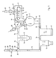
- Fig. 1 shows an inventive incineration plant, which comprises a drying plant according to the invention.
- the incinerator accordingly has a furnace 1 with boilers in which the heat of combustion for heating water or thermal oil eg for heating purposes is being used.
- a discharge 2 is arranged at the lower end of the furnace 1.
- a material feed 3 is followed immediately by a material feed of a subsequent drying plant 4, which comprises a belt dryer 5, a following in the material flow direction on this following Vorsilo 6 and a subsequent rotor dryer 7.
- a closed screen belt 8 is arranged with an upper run and a lower run, which run over several rollers. Its right end is below the material task 3, its left end above the Vorsilos 6.
- a heater 9 is also attached.
- the Vorsilo 6 is closed in the region of its lower end by a designed as a flap 10 separating device, i. separable from the subsequent rotor dryer 7.
- a flap 11 separating device At the lower end of the rotor dryer 7 is also closed by a designed as a flap 11 separating device, so that it can be separated from a bottom subsequent drying silo 12.
- the dry silo 12 is conveyed by a conveyor 13, e.g. Screw conveyor, chain conveyor or a moving floor, connected to the furnace 1. If the drying plant is not used for drying fuel or is not used in an incinerator, by contrast a discharge for dried material is arranged below the drying hopper, which can then be reused, e.g. as starting material for the production of pellets.
- a flue gas line 14 goes out, at the successive in terms of flow direction, a pre-separator 15 and, combined in a single unit, a precooler 16 and a Spark detection path 17 with a common dust collecting vessel are arranged.
- a hot gas guide passes through the rotor dryer 7 and the belt dryer 5 and comprises a parallel to Vorsilo 6 connecting portion 18 between them. The latter opens into an outlet 19 above the right end of the screen belt 8 or laterally thereof.
- a trigger 20 is arranged, which is connected via a fan 21 with a chimney 22. If very low dust levels of the exhaust gas are required, a filter, for example a fabric filter, can be installed in front of the fan 21 for dedusting the exhaust gas.
- a condenser in which the exhaust gas is cooled can be provided in front of the fan 21 and optionally after the filter.
- the condensation heat removed from the exhaust gas can be used.
- a heating register 23 is arranged in the area of the mouth of the hot gas guide in the rotor dryer 7.
- the hot gas guide comprises an air feed 24 with a fan 25.
- the flue gas line 14 opens between the fan 25 and the rotor dryer 7 in the hot gas guide.
- drying plant is not used within the framework of an incineration plant, ie not together with a firing plant, then there is merely an air feed as described, via which air or hot air is usually supplied as hot gas.
- a passage 26 is arranged, which the flue gas line 14 directly to the connecting portion 18th combines.
- a switch designed as a flap 27 closes the passage 26 in a first position, so that the air feed 24 and the flue gas line 14 are connected only via the rotor dryer 7 to the connecting section 18 and further to the belt dryer 5, while in a second position the passage 26 leaves open, but the rotor dryer 7 separates from the connecting portion 18, so that the air supply line 24 and the flue gas line 14 with this and the belt dryer 5 directly, bypassing the rotor dryer 7, are connected.
- a bypass branch 28 from the flue gas line 14 with, a bypass line 29, which leads via a closing device designed as a flap 30 and a fan 31 to a chimney 32.
- a closing device designed as a flap 30 and a fan 31 to a chimney 32.
- Another flap 33 is arranged with respect to the flow direction of the flue gas just behind the junction of the bypass line 29 of the flue gas duct 14 in the latter.
- the material usually wet biomass such as sawdust or woodchips, whose material flow is indicated by solid arrows is introduced through the material task 3 and falls on the belt dryer 5, more precisely on the right end of the upper run of the wire 8, on which it is a uniformly thick Layer forms. From this it is slowly transported to the left end of the said strand, from which it falls into the prefix 6.
- the flap 10 is usually closed, so that the material accumulates in Vorsilo 6 for a while. Then, the flap 10 is opened for a short time and accumulated in Vorsilo 6 material falls into the rotor dryer. 7
- the flap 11 of the rotor dryer 7 is opened and the material falls into the underlying drying silo 12. From there it transports the conveyor 13 into the furnace 1, where it is burned. The flap 11 is closed again and the flap 10 is opened briefly, so that the accumulated in Vorsilo 6 material falls into the rotor dryer 7 and the same is reloaded.
- the flue gas From the furnace 1, the flue gas, whose flow is indicated by long-dashed arrows, first flows into the pre-separator 15, where larger dust and ash particles are separated and discharged and on to the precooler 16 and the spark detection path 17, where any spark is detected and deleted, so that further transport of burning particles into the drying plant 4 is prevented.
- a hot gas By targeted mixture of cooler fresh air (short dashed arrow) or exhaust air from other parts of the drying plant or a mixture of fresh air and exhaust air with the flue gas, a hot gas is produced, the temperature is below a threshold temperature before it is passed into the rotor dryer 7 and on the material hits.
- the limit temperature is set so that evaporation of hydrocarbons from the material, which could lead to undesirable contamination of the hot gas (formation of 'blue haze'), is avoided.
- the limit temperature depends on the type of material. For wood, it is about 120 ° C. If necessary, additional hot air can be introduced into the rotor dryer 7 to increase the dryer output with the heating register 23.
- the hot gas strikes the material and promotes its drying, thereby cooling itself, i. Energy, composed of sensible heat and the condensation of water vapor resulting condensation heat, gives off. It then flows through the connecting section 18 further into the belt dryer 5, where it exits from the outlet 19 in the region lying over the left end of the wire 8. Since at the same time by the fan 21 at the trigger 20, a negative pressure is generated, the flue gas-air mixture flows from top to bottom through die.Schicht of moist material, which lies on the upper run of the screen belt 8 and through said upper strand. In this case, the material, in turn, with cooling of the hot gas, pre-dried before it enters the rotor dryer 7.
- the hot gas is filtered by flowing through the layer of material.
- small dust and ash particles are deposited. Therefore, the hot gas usually meets the legal requirements, which set the usual upper limits for the dust content and can be blown off without exhaustive cleaning measures as exhaust gas through the chimney 22 into the open.
- the chimney may be preceded by a filter or a condenser or both.
- the drying of the material can be supported by the heating register 9. While the flap 27 is usually in the in Fig. 1 shown, so that the hot gas flows through the rotor dryer 7, it is held during the unloading and reloading of the rotor dryer 7 in the second position in which the flue gas-air mixture directly, bypassing the rotor dryer 7, from the Flue gas duct 14 flows into the connecting portion 18 and further into the belt dryer 5.
- the bypass branch 28 allows it to be used in emergencies, e.g. in case of a fault in the drying plant 4, the passage of the flue gas through the same to interrupt.
- the precooler is not essential, since sufficient cooling can be achieved by fresh air alone.
- the heating registers can also often be omitted.
- the drying plant can also be used independently of a furnace and instead of flue gas or a flue gas-air mixture, for example. Only hot air can be used as hot gas.
Abstract
Die Verbrennungsanlage umfasst eine Feuerungsanla.ge (1), eine Trocknungsanlage (4) mit einem Bandtrockner (5) und einem Rotortrockner (7) sowie eine Materialaufgabe (3), welche über die Trocknungsanlage (4) mit der Feuerungsanlage (1) verbunden ist. Eine Heissgasführung verbindet eine Luftzuführung (24) über den Rotortrockner (7) und den Bandtrockner (5) mit einem Kamin (22). In Strörriungsrichtung des Heissgases vor der Trocknungsanlage (4) mündet eine von der Feuerungsanlage (1) ausgehende Rauchgasleitung (14) in dieselbe. Dies ermöglicht die Herstellung eines Rauchgas-Luft-Gemisches als Heissgas mit einer gewünschten. Temperatur. In der Trocknungsanlage (4) gibt dasselbe Wärme an das Material ab und unterstützt dadurch die Trocknung desselben. Dabei durchströmt das Heissgas im Bandtrockner (5) ein oberes Trum eines Siebbandes (8) und eine auf diesem liegende Materialschicht, wobei es zugleich gefiltert und entstaubt wird.The incinerator comprises a Feuerungsanla.ge (1), a drying plant (4) with a belt dryer (5) and a Rotortrockner (7) and a material task (3) which is connected via the drying plant (4) with the furnace (1) , A hot gas duct connects an air supply (24) via the rotor dryer (7) and the belt dryer (5) with a chimney (22). In Strörriungsrichtung of the hot gas before the drying plant (4) emanates from the furnace (1) outgoing flue gas line (14) in the same. This allows the production of a flue gas-air mixture as a hot gas with a desired. Temperature. In the drying plant (4) it gives off heat to the material and thereby supports the drying of the same. In this case, the hot gas in the belt dryer (5) flows through an upper run of a screen belt (8) and a layer of material lying on it, wherein it is at the same time filtered and dedusted.
Description
Die Erfindung betrifft eine Trocknungsanlage zur Trocknung von feuchtem Material, vor allem Biomasse wie Holz, insbesondere in der Form von Holzschnitzeln, Sägespänen oder zerkleinerter Holzrinde. Ausserdem betrifft sie eine Verbrennungsanlage, welche eine derartige Trocknungsanlage umfasst.The invention relates to a drying plant for drying moist material, especially biomass such as wood, especially in the form of wood chips, sawdust or crushed wood bark. It also relates to a combustion plant comprising such a drying plant.
Gattungsgemässe im wesentlichen aus einem Bandtrockner bestehende Anlagen zur Trocknung von feuchtem Material sind bekannt. Der Feuchtigkeitsgehalt des getrockneten Materials ist bei solchen Anlagen jedoch schlecht einstellbar und schwankt meist stark, sodass bei seiner weiteren Verwendung oft Schwierigkeiten auftreten oder zur Einstellung eines erwünschten Feuchtigkeitsgehalts energetisch ungünstige oder sonstige den Aufwand erhöhende Massnahmen erforderlich sind wie Mischung mit trockenem Material oder auch Zumischung von Wasser.Generic systems essentially consisting of a belt dryer for drying moist material are known. However, the moisture content of the dried material is poorly adjustable in such systems and usually varies greatly, so that difficulties arise in its further use or to set a desired moisture content energetically unfavorable or other cost-increasing measures are required as mixing with dry material or admixture of Water.
Der Erfindung liegt die Aufgabe zu Grunde, gattungsgemässe Trocknungsanlagen bezüglich der Einstellung des Feuchtigkeitsgehalts des getrockneten Materials zu verbessern, und zwar auf eine Weise, welche einen energiesparenden Betrieb ermöglicht. Diese Aufgabe wird durch die Erfindung, wie sie in den Ansprüchen gekennzeichnet ist, gelöst.The invention is based on the object to improve generic drying equipment with respect to the adjustment of the moisture content of the dried material, in a manner which allows energy-saving operation. This task will solved by the invention as characterized in the claims.
Bei erfindungsgemässen Anlagen wird das Material im Bandtrockner vorgetrocknet und dann in einem Rotortrockner, in dem der Trocknungsgrad gut steuerbar ist, bis zum erwünschten Feuchtigkeitsgehalt fertiggetrocknet. Die tieferen Temperaturen im Bandtrockner erlauben dabei, Heissgas, gewöhnlich Rauchgas oder Heissluft, das bereits im Rotortrockner eingesetzt wurde, im Bandtrockner weiterzuverwenden. Dadurch wird eine erhebliche Energieeinsparung erzielt. Besonders ausgeprägt ist die Energieeinsparung, wenn die Trocknungsanlage Teil einer Verbrennungsanlage ist und die bei der Verbrennung entstehenden Rauchgase in der Trocknungsanlage eingesetzt werden.In the case of plants according to the invention, the material is predried in the belt dryer and then finish-dried to the desired moisture content in a rotor dryer in which the degree of drying is easily controllable. The lower temperatures in the belt dryer make it possible to continue to use hot gas, usually flue gas or hot air, which has already been used in the rotor dryer, in the belt dryer. As a result, a considerable energy saving is achieved. The energy saving is particularly pronounced when the drying plant is part of a combustion plant and the flue gases produced during combustion are used in the drying plant.
Im folgenden wird die Erfindung anhand einer Figur, welche lediglich ein Ausführungsbeispiel darstellt, näher erläutert.
- Fig. 1
- zeigt schematisch den Aufbau einer erfindungsgemässen Verbrennungsanlage.
- Fig. 1
- schematically shows the structure of an inventive combustion system.
Auf eine Materialaufgabe 3 folgt unmittelbar ein Materialeintrag einer anschliessenden Trocknungsanlage 4, welche einen Bandtrockner 5, einen in Materialflussrichtung auf diesen folgenden Vorsilo 6 und einen anschliessenden Rotortrockner 7 umfasst. Im Bandtrockner 5 ist ein geschlossenes Siebband 8 mit einem oberen Trum und einem unteren Trum angeordnet, die über mehrere Rollen laufen. Sein rechtes Ende liegt unterhalb der Materialaufgabe 3, sein linkes Ende oberhalb des Vorsilos 6. Im Deckenbereich ist ausserdem ein Heizregister 9 angebracht. Das Vorsilo 6 ist im Bereich seines unteren Endes durch eine als Klappe 10 ausgebildete Trennvorrichtung verschliessbar, d.h. vom anschliessenden Rotortrockner 7 trennbar.A material feed 3 is followed immediately by a material feed of a
Am unteren Ende ist der Rotortrockner 7 ebenfalls durch eine als Klappe 11 ausgebildete Trennvorrichtung verschliessbar, sodass er von einem unten anschliessenden Trockensilo 12 getrennt werden kann. Der Trockensilo 12 ist durch eine Förderanlage 13, z.B. Förderschnecken, Kettenförderer oder ein Schubboden, mit der Feuerungsanlage 1 verbunden. Falls die Trocknungsanlage nicht der Trocknung von Brennmaterial dient oder gar nicht im Rahmen einer Verbrennungsanlage eingesetzt wird, so ist dagegen unterhalb des Trockehsilos ein Austrag für getrocknetes Material angeordnet, das dann auch anders weiterverwendet werden kann, z.B. als Ausgangsmaterial für die Herstellung von Pellets.At the lower end of the
Von der Feuerungsanlage 1 geht eine Rauchgasleitung 14 aus, an der hinsichtlich der Strömungsrichtung aufeinanderfolgend ein Vorabscheider 15 sowie, in einer Baueinheit zusammengefasst, ein Vorkühler 16 und eine Funkenerkennungsstrecke 17 mit einem gemeinsamen Staubsammelgefäss, angeordnet sind. Eine Heissgasführung führt durch den Rotortrockner 7 und den Bandtrockner 5 und umfasst einen zum Vorsilo 6 parallelen Verbindungsabschnitt 18 zwischen denselben. Letzterer mündet in einen Auslass 19 oberhalb des rechten Endes des Siebbandes 8 oder seitlich davon. Unterhalb des oberen Trums des Siebbandes 8 ist ein Abzug 20 angeordnet, der über einen Ventilator 21 mit einem Kamin 22 verbunden ist. Falls sehr niedrige Staubwerte des Abgases gefordert werden, kann vor dem Ventilator 21 ein Filter, z.B. ein Gewebefilter, zur Entstaubung des Abgases eingebaut sein. Vor dem Ventilator 21 und gegebenenfalls nach dem Filter kann ausserdem ein Kondensator vorgesehen sein, in dem das Abgas gekühlt wird. Die dem Abgas entzogene Kondensationswärme kann genutzt werden. Im Bereich der Mündung der Heissgasführung in den Rotortrockner 7 ist ein Heizregister 23 angeordnet.From the furnace 1, a
Die Heissgasführung umfasst eine Luftzuführung 24 mit einem Ventilator 25. Die Rauchgasleitung 14 mündet zwischen dem Ventilator 25 und dem Rotortrockner 7 in die Heissgasführung. So kann aus dem Rauchgas und aus Frischluft oder auch Abluft aus anderen Teilen der Verbrennungsanlage ein Rauchgas-Luft-Gemisch als Heissgas hergestellt werden.The hot gas guide comprises an
Wird die Trocknungsanlage nicht im Rahmen einer Verbrennungsanlage, also nicht zusammen mit einer Feuerungsanlage eingesetzt, so ist lediglich eine Luftzuführung wie beschrieben vorhanden, über die gewöhnlich Luft oder Heissluft als Heissgas zugeführt wird.If the drying plant is not used within the framework of an incineration plant, ie not together with a firing plant, then there is merely an air feed as described, via which air or hot air is usually supplied as hot gas.
Im Bereich der Mündung der Heissgasführung in den Rotortrockner 7 ist ein Durchlass 26 angeordnet, der die Rauchgasleitung 14 direkt mit dem Verbindungsabschnitt 18 verbindet. Eine als Klappe 27 ausgebildete Weiche verschliesst in einer ersten Stellung den Durchlass 26, sodass die Luftzuführung 24 und die Rauchgasleitung 14 nur über den Rotortrockner 7 mit dem Verbindungsabschnitt 18 und weiter mit dem Bandtrockner 5 verbunden sind, während sie in einer zweiten Stellung den Durchlass 26 offen lässt, aber den Rotortrockner 7 vom Verbindungsabschnitt 18 trennt, sodass die Luftzuführung 24 und die Rauchgasleitung 14 mit diesem und dem Bandtrockner 5 direkt, unter Umgehung des Rotortrockners 7, verbunden sind.In the region of the mouth of the hot gas guide in the
Zwischen dem Vorabscheider 15 und dem Vorkühler 16 zweigt ein Umgehungszweig 28 von der Rauchgasleitung 14 ab, mit, einer Umgehungsleitung 29, welche über eine als Klappe 30 ausgebildete Schliessvorrichtung und einen Ventilator 31 zu einem Kamin 32 führt. Eine weitere Klappe 33 ist hinsichtlich der Strömungsrichtung des Rauchgases knapp hinter der Abzweigung der Umgehungsleitung 29 von der Rauchgasleitung 14 in der letzteren angeordnet.Between the
Das Material, gewöhnlich feuchte Biomasse wie Sägespäne oder Hackschnitzel, dessen Materialfluss durch durchgezogene Pfeile angedeutet ist, wird über die Materialaufgabe 3 eingeführt und fällt auf den Bandtrockner 5, genauer auf den rechten Endbereich des oberen Trums des Siebbandes 8, auf dem es eine gleichmässig dicke Schicht bildet. Von diesem wird es langsam zum linken Ende des besagten Trums transportiert, von dem es in das Vorsilo 6 fällt. Die klappe 10 ist gewöhnlich geschlossen, sodass sich das Material im Vorsilo 6 eine Zeit lang ansammelt. Dann wird die Klappe 10 kurzzeitig geöffnet und das im Vorsilo 6 angesammelte Material fällt in den Rotortrockner 7.The material, usually wet biomass such as sawdust or woodchips, whose material flow is indicated by solid arrows is introduced through the material task 3 and falls on the
Nach einer vorgegebenen Trocknungszeit oder wenn es einen vorbestimmten Feuchtigkeitsgehalt unterschreitet, wird die Klappe 11 des Rotortrockners 7 geöffnet und das Material fällt in den darunterliegenden Trockensilo 12. Von dort transportiert es die Förderanlage 13 in die Feuerungsanlage 1, wo es verbrannt wird. Die Klappe 11 wird wieder geschlossen und die Klappe 10 kurz geöffnet, sodass das im Vorsilo 6 angesammelte Material in den Rotortrockner 7 fällt und derselbe neu beladen wird.After a predetermined drying time or when it falls below a predetermined moisture content, the
Von der Feuerungsanlage 1 strömt das Rauchgas, dessen Strömung durch langgestrichelte Pfeile abgedeutet ist, zuerst in den Vorabscheider 15, wo grössere Staub- und Aschepartikel abgeschieden und ausgebracht werden und weiter zum Vorkühler 16 und zur Funkenerkennungsstrecke 17, wo allfälliger Funkenflug erkannt und gelöscht wird, sodass ein Weitertransport von brennenden Partikeln in die Trocknungsanlage 4 verhindert wird. Durch gezielte Mischung von kühlerer Frischluft (kurzgestrichelter Pfeil) oder auch Abluft aus anderen Teilen der Trocknungsanlage oder einer Mischung von Frischluft und Abluft mit dem Rauchgas wird ein Heissgas hergestellt, dessen Temperatur unter einer Grenztemperatur liegt, bevor es in den Rotortrockner 7 geleitet wird und auf das Material trifft. Die Grenztemperatur ist dabei so festgelegt, dass ein Ausdampfen von Kohlenwasserstoffen aus dem Material, das zu einer unerwünschten Verunreinigung des Heissgases (Bildung von 'blue haze') führen könnte, vermieden wird. Die Grenztemperatur hängt von der Art des Materials ab. Bei Holz beträgt sie ca. 120°C. Wenn nötig kann zur Erhöhung der Trocknerleistung mit dem Heizregister 23 zusätzliche Warmluft in den Rotortrockner 7 eingeleitet werden.From the furnace 1, the flue gas, whose flow is indicated by long-dashed arrows, first flows into the pre-separator 15, where larger dust and ash particles are separated and discharged and on to the
Im Rotortrockner 7 trifft das Heissgas auf das Material und fördert dessen Trocknung, wobei es sich selbst abkühlt, d.h. Energie, zusammengesetzt aus fühlbarer Wärme und beim Auskondensieren von Wasserdampf entstehender Kondensationswärme, abgibt. Es strömt dann durch den Verbindungsabschnitt 18 weiter in den Bandtrockner 5, wo es aus dem Auslass 19 in den über dem linken Ende des Siebbandes 8 liegenden Bereich austritt. Da zugleich durch den Ventilator 21 am Abzug 20 ein Unterdruck erzeugt wird, strömt das Rauchgas-Luft-Gemisch von oben nach unten durch die.Schicht von feuchtem Material, die auf dem oberen Trum des Siebbandes 8 liegt und durch das besagte obere Trum. Dabei wird das Material, wiederum unter Abkühlung des Heissgases, vorgetrocknet, bevor es in den Rotortrockner 7 gelangt.In the
Zugleich wird das Heissgas, indem es durch die Materialschicht strömt, gefiltert. Insbesondere werden kleine Staub- und Aschepartikel abgeschieden. Das Heissgas genügt deshalb gewöhnlich den gesetzlichen Bestimmungen, welche übliche Obergrenzen für den Staubgehalt festlegen und kann ohne weitere Reinigungsmassnahmen als Abgas durch den Kamin 22 ins Freie abgeblasen werden. Bei besonders hohen Anforderungen kann wie erwähnt dem Kamin ein Filter oder ein Kondensator oder beides vorgeordnet sein.At the same time, the hot gas is filtered by flowing through the layer of material. In particular, small dust and ash particles are deposited. Therefore, the hot gas usually meets the legal requirements, which set the usual upper limits for the dust content and can be blown off without exhaustive cleaning measures as exhaust gas through the
Die Trocknung des Materials kann durch das Heizregister 9 unterstützt werden. Während die Klappe 27 gewöhnlich in der in
Bei der beschriebenen Betriebsweise, bei der das aus Rauchgas und Luft zusammengemischte Heissgas meist sowohl durch den Rotortrockner 7 als auch durch den Bandtrockner 5 geleitet wird, wird die Wärme des Rauchgases so weit wie möglich ausgenützt und die Trocknung optimiert.In the described mode of operation, in which the hot gas mixed together from flue gas and air is usually passed both through the
Der Umgehungszweig 28'erlaubt es, in Notfällen, z.B. bei einer Störung in der Trocknungsanlage 4, die Durchleitung des Rauchgases durch die dieselbe zu unterbrechen.The bypass branch 28 'allows it to be used in emergencies, e.g. in case of a fault in the
Es sind verschiedene Abwandlungen des oben'beschriebenen Ausführungsbeispiels möglich, ohne dass der Bereich der Erfindung verlassen würde. So ist insbesondere der Vorkühler nicht unbedingt erforderlich, da eine ausreichende Kühlung auch durch Frischluftzufuhr allein erzielt werden kann. Die Heizregister können ebenfalls oft entfallen.Various modifications of the above-described embodiment are possible without departing from the scope of the invention. Thus, in particular, the precooler is not essential, since sufficient cooling can be achieved by fresh air alone. The heating registers can also often be omitted.
Wie erwähnt kann die Trocknungsanlage auch unabhängig von einer Feuerungsanlage eingesetzt werden und statt Rauchgas oder einem Rauchgas-Luft-Gemisch z.B. ausschliesslich Heissluft als Heissgas eingesetzt werden.As mentioned, the drying plant can also be used independently of a furnace and instead of flue gas or a flue gas-air mixture, for example. Only hot air can be used as hot gas.
- 11
- Feuerungsanlagefurnace
- 22
- Austragdischarge
- 33
- Materialaufgabematerial feed
- 44
- Trocknungsanlagedrying plant
- 55
- Bandtrocknerbelt dryer
- 66
- Vorsilopilot silo
- 77
- Rotortrocknerrotor dryer
- 88th
- Siebbandscreen belt
- 99
- Heizregisterheater
- 1010
- Klappeflap
- 1111
- Klappeflap
- 1212
- Trockensilodrying silo
- 1313
- Förderanlageconveyor system
- 1414
- RauchgasleitungFlue gas line
- 1515
- Vorabscheiderpre-separator
- 1616
- Vorkühlerprecooler
- 1717
- FunkenerkennungsstreckeSpark detection distance
- 1818
- Verbindungsabschnittconnecting portion
- 1919
- Auslassoutlet
- 2020
- Abzugdeduction
- 2121
- Ventilatorfan
- 2222
- Kaminfireplace
- 2323
- Heizregisterheater
- 2424
- Luftzuführungair supply
- 2525
- Ventilatorfan
- 2626
- Durchlasspassage
- 2727
- Klappeflap
- 2828
- Umgehungszweigpass branch
- 2929
- Umgehungsleitungbypass line
- 3030
- Klappeflap
- 3131
- Ventilatorfan
- 3232
- Kaminfireplace
- 3333
- Klappeflap
Claims (10)
Applications Claiming Priority (1)
| Application Number | Priority Date | Filing Date | Title |
|---|---|---|---|
| CH02007/13A CH708975B1 (en) | 2013-12-04 | 2013-12-04 | Incinerator. |
Publications (2)
| Publication Number | Publication Date |
|---|---|
| EP2889537A1 true EP2889537A1 (en) | 2015-07-01 |
| EP2889537B1 EP2889537B1 (en) | 2018-03-07 |
Family
ID=52146400
Family Applications (1)
| Application Number | Title | Priority Date | Filing Date |
|---|---|---|---|
| EP14405092.9A Not-in-force EP2889537B1 (en) | 2013-12-04 | 2014-11-28 | Combustion facility with drying plant |
Country Status (2)
| Country | Link |
|---|---|
| EP (1) | EP2889537B1 (en) |
| CH (1) | CH708975B1 (en) |
Cited By (1)
| Publication number | Priority date | Publication date | Assignee | Title |
|---|---|---|---|---|
| EP3351885A1 (en) | 2017-01-23 | 2018-07-25 | Rupert Kaindl | Method for operating a drying plant for moist wood drying plant |
Citations (4)
| Publication number | Priority date | Publication date | Assignee | Title |
|---|---|---|---|---|
| EP0714006A1 (en) * | 1994-11-24 | 1996-05-29 | W. Kunz AG | Process for drying a substance, in particular wood chips |
| US5749160A (en) * | 1995-02-14 | 1998-05-12 | George Koch Sons, Inc. | Multi-zone method for controlling voc and nox emissions in a flatline conveyor wafer drying system |
| US20110030235A1 (en) * | 2008-01-10 | 2011-02-10 | Zdenek Brancuzsky | Method for continuously drying bulk goods, in particular wood fibers and/or wood chips |
| DE102011015769A1 (en) * | 2011-04-01 | 2012-10-04 | Christian Wenner | Device for drying of substrate e.g. wood chip, has container that acts as drying zone, to which the to-be-dried product is supplied |
-
2013
- 2013-12-04 CH CH02007/13A patent/CH708975B1/en not_active IP Right Cessation
-
2014
- 2014-11-28 EP EP14405092.9A patent/EP2889537B1/en not_active Not-in-force
Patent Citations (4)
| Publication number | Priority date | Publication date | Assignee | Title |
|---|---|---|---|---|
| EP0714006A1 (en) * | 1994-11-24 | 1996-05-29 | W. Kunz AG | Process for drying a substance, in particular wood chips |
| US5749160A (en) * | 1995-02-14 | 1998-05-12 | George Koch Sons, Inc. | Multi-zone method for controlling voc and nox emissions in a flatline conveyor wafer drying system |
| US20110030235A1 (en) * | 2008-01-10 | 2011-02-10 | Zdenek Brancuzsky | Method for continuously drying bulk goods, in particular wood fibers and/or wood chips |
| DE102011015769A1 (en) * | 2011-04-01 | 2012-10-04 | Christian Wenner | Device for drying of substrate e.g. wood chip, has container that acts as drying zone, to which the to-be-dried product is supplied |
Cited By (1)
| Publication number | Priority date | Publication date | Assignee | Title |
|---|---|---|---|---|
| EP3351885A1 (en) | 2017-01-23 | 2018-07-25 | Rupert Kaindl | Method for operating a drying plant for moist wood drying plant |
Also Published As
| Publication number | Publication date |
|---|---|
| CH708975A2 (en) | 2015-06-15 |
| EP2889537B1 (en) | 2018-03-07 |
| CH708975B1 (en) | 2016-07-15 |
Similar Documents
| Publication | Publication Date | Title |
|---|---|---|
| EP2388542B1 (en) | Method and apparatus for continuous drying of bulk material, in particular of wood fibres and/or wood chippings | |
| EP2771302B1 (en) | Method and device for reprocessing wet waste materials containing organic components | |
| EP0950855A2 (en) | Method and device for the incineration of particulate solids | |
| DE2556046A1 (en) | METHOD AND DEVICE FOR HEAT TREATMENT OF MATERIAL | |
| DE3010909A1 (en) | METHOD AND DEVICE FOR BURNING FINE-GRAINED GOODS AND FOR GENERATING CARBON DUST | |
| AT401420B (en) | DEVICE FOR BURNING BIOMASS | |
| CH628972A5 (en) | Tunnel furnace with direct firing | |
| EP0043567A1 (en) | Method of and grate furnace for combustion of solid fuel | |
| EP2375152B1 (en) | Device and method for generating hot gas with integrated heating of a heat distribution medium | |
| EP2889537B1 (en) | Combustion facility with drying plant | |
| DE102015003856A1 (en) | Device for controlling the temperature of objects | |
| DE2256034C3 (en) | Device for the heat treatment of goods on a traveling grate | |
| EP0030376A2 (en) | Process and apparatus for drying and preheating moist coal | |
| EP0058892B1 (en) | Process and apparatus for drying of cereals with hot air | |
| DE2161410B2 (en) | Method and device for drying, pre-burning and final burning of pellets from cement raw meal | |
| EP0170304B1 (en) | Clinker cooler with dedusting device in a process for the production of cement | |
| DE102016103685B4 (en) | Continuous dryer with at least two sections | |
| EP0501944B1 (en) | Method and device for combustion of lump biogenic fuels | |
| DE4312900C2 (en) | Method and arrangement for operating a pre-firing with biofuel combustion for a coal-fired steam boiler | |
| DE1758143B2 (en) | MULTI-STAGE SYSTEM FOR PRE-HEATING RAW CEMENT FLOUR OR SIMILAR FINE-GRAINED MATERIAL | |
| EP1085283A2 (en) | Installation for the cleaning and burning of shaft furnace exhaust gases | |
| CH651644A5 (en) | COOLED COMBUSTION ROOM WITH A FLUIDIZED BURN COMBUSTION AND METHOD FOR OPERATING THE SAME. | |
| DE942679C (en) | Lime or zenent shaft furnace with attached dedusting system that works with filter surfaces | |
| DE467028C (en) | Exhaust-heated drying system | |
| DE1163295B (en) | Process to improve the electrical dedusting of the exhaust gases from Oven for the treatment of dry feed material |
Legal Events
| Date | Code | Title | Description |
|---|---|---|---|
| PUAI | Public reference made under article 153(3) epc to a published international application that has entered the european phase |
Free format text: ORIGINAL CODE: 0009012 |
|
| 17P | Request for examination filed |
Effective date: 20141128 |
|
| AK | Designated contracting states |
Kind code of ref document: A1 Designated state(s): AL AT BE BG CH CY CZ DE DK EE ES FI FR GB GR HR HU IE IS IT LI LT LU LV MC MK MT NL NO PL PT RO RS SE SI SK SM TR |
|
| AX | Request for extension of the european patent |
Extension state: BA ME |
|
| R17P | Request for examination filed (corrected) |
Effective date: 20151217 |
|
| RBV | Designated contracting states (corrected) |
Designated state(s): AL AT BE BG CH CY CZ DE DK EE ES FI FR GB GR HR HU IE IS IT LI LT LU LV MC MK MT NL NO PL PT RO RS SE SI SK SM TR |
|
| RIC1 | Information provided on ipc code assigned before grant |
Ipc: F23K 1/00 20060101AFI20170912BHEP |
|
| GRAP | Despatch of communication of intention to grant a patent |
Free format text: ORIGINAL CODE: EPIDOSNIGR1 |
|
| INTG | Intention to grant announced |
Effective date: 20171020 |
|
| GRAS | Grant fee paid |
Free format text: ORIGINAL CODE: EPIDOSNIGR3 |
|
| GRAA | (expected) grant |
Free format text: ORIGINAL CODE: 0009210 |
|
| AK | Designated contracting states |
Kind code of ref document: B1 Designated state(s): AL AT BE BG CH CY CZ DE DK EE ES FI FR GB GR HR HU IE IS IT LI LT LU LV MC MK MT NL NO PL PT RO RS SE SI SK SM TR |
|
| REG | Reference to a national code |
Ref country code: GB Ref legal event code: FG4D Free format text: NOT ENGLISH |
|
| REG | Reference to a national code |
Ref country code: CH Ref legal event code: EP Ref country code: AT Ref legal event code: REF Ref document number: 976973 Country of ref document: AT Kind code of ref document: T Effective date: 20180315 |
|
| REG | Reference to a national code |
Ref country code: IE Ref legal event code: FG4D Free format text: LANGUAGE OF EP DOCUMENT: GERMAN |
|
| REG | Reference to a national code |
Ref country code: DE Ref legal event code: R096 Ref document number: 502014007520 Country of ref document: DE |
|
| REG | Reference to a national code |
Ref country code: NL Ref legal event code: MP Effective date: 20180307 |
|
| REG | Reference to a national code |
Ref country code: LT Ref legal event code: MG4D |
|
| PG25 | Lapsed in a contracting state [announced via postgrant information from national office to epo] |
Ref country code: ES Free format text: LAPSE BECAUSE OF FAILURE TO SUBMIT A TRANSLATION OF THE DESCRIPTION OR TO PAY THE FEE WITHIN THE PRESCRIBED TIME-LIMIT Effective date: 20180307 Ref country code: CY Free format text: LAPSE BECAUSE OF FAILURE TO SUBMIT A TRANSLATION OF THE DESCRIPTION OR TO PAY THE FEE WITHIN THE PRESCRIBED TIME-LIMIT Effective date: 20180307 Ref country code: LT Free format text: LAPSE BECAUSE OF FAILURE TO SUBMIT A TRANSLATION OF THE DESCRIPTION OR TO PAY THE FEE WITHIN THE PRESCRIBED TIME-LIMIT Effective date: 20180307 Ref country code: FI Free format text: LAPSE BECAUSE OF FAILURE TO SUBMIT A TRANSLATION OF THE DESCRIPTION OR TO PAY THE FEE WITHIN THE PRESCRIBED TIME-LIMIT Effective date: 20180307 Ref country code: HR Free format text: LAPSE BECAUSE OF FAILURE TO SUBMIT A TRANSLATION OF THE DESCRIPTION OR TO PAY THE FEE WITHIN THE PRESCRIBED TIME-LIMIT Effective date: 20180307 Ref country code: NO Free format text: LAPSE BECAUSE OF FAILURE TO SUBMIT A TRANSLATION OF THE DESCRIPTION OR TO PAY THE FEE WITHIN THE PRESCRIBED TIME-LIMIT Effective date: 20180607 |
|
| PG25 | Lapsed in a contracting state [announced via postgrant information from national office to epo] |
Ref country code: GR Free format text: LAPSE BECAUSE OF FAILURE TO SUBMIT A TRANSLATION OF THE DESCRIPTION OR TO PAY THE FEE WITHIN THE PRESCRIBED TIME-LIMIT Effective date: 20180608 Ref country code: BG Free format text: LAPSE BECAUSE OF FAILURE TO SUBMIT A TRANSLATION OF THE DESCRIPTION OR TO PAY THE FEE WITHIN THE PRESCRIBED TIME-LIMIT Effective date: 20180607 Ref country code: RS Free format text: LAPSE BECAUSE OF FAILURE TO SUBMIT A TRANSLATION OF THE DESCRIPTION OR TO PAY THE FEE WITHIN THE PRESCRIBED TIME-LIMIT Effective date: 20180307 Ref country code: LV Free format text: LAPSE BECAUSE OF FAILURE TO SUBMIT A TRANSLATION OF THE DESCRIPTION OR TO PAY THE FEE WITHIN THE PRESCRIBED TIME-LIMIT Effective date: 20180307 Ref country code: SE Free format text: LAPSE BECAUSE OF FAILURE TO SUBMIT A TRANSLATION OF THE DESCRIPTION OR TO PAY THE FEE WITHIN THE PRESCRIBED TIME-LIMIT Effective date: 20180307 |
|
| PG25 | Lapsed in a contracting state [announced via postgrant information from national office to epo] |
Ref country code: MT Free format text: LAPSE BECAUSE OF FAILURE TO SUBMIT A TRANSLATION OF THE DESCRIPTION OR TO PAY THE FEE WITHIN THE PRESCRIBED TIME-LIMIT Effective date: 20180307 |
|
| PG25 | Lapsed in a contracting state [announced via postgrant information from national office to epo] |
Ref country code: RO Free format text: LAPSE BECAUSE OF FAILURE TO SUBMIT A TRANSLATION OF THE DESCRIPTION OR TO PAY THE FEE WITHIN THE PRESCRIBED TIME-LIMIT Effective date: 20180307 Ref country code: AL Free format text: LAPSE BECAUSE OF FAILURE TO SUBMIT A TRANSLATION OF THE DESCRIPTION OR TO PAY THE FEE WITHIN THE PRESCRIBED TIME-LIMIT Effective date: 20180307 Ref country code: PL Free format text: LAPSE BECAUSE OF FAILURE TO SUBMIT A TRANSLATION OF THE DESCRIPTION OR TO PAY THE FEE WITHIN THE PRESCRIBED TIME-LIMIT Effective date: 20180307 Ref country code: EE Free format text: LAPSE BECAUSE OF FAILURE TO SUBMIT A TRANSLATION OF THE DESCRIPTION OR TO PAY THE FEE WITHIN THE PRESCRIBED TIME-LIMIT Effective date: 20180307 Ref country code: NL Free format text: LAPSE BECAUSE OF FAILURE TO SUBMIT A TRANSLATION OF THE DESCRIPTION OR TO PAY THE FEE WITHIN THE PRESCRIBED TIME-LIMIT Effective date: 20180307 Ref country code: IT Free format text: LAPSE BECAUSE OF FAILURE TO SUBMIT A TRANSLATION OF THE DESCRIPTION OR TO PAY THE FEE WITHIN THE PRESCRIBED TIME-LIMIT Effective date: 20180307 |
|
| PG25 | Lapsed in a contracting state [announced via postgrant information from national office to epo] |
Ref country code: SM Free format text: LAPSE BECAUSE OF FAILURE TO SUBMIT A TRANSLATION OF THE DESCRIPTION OR TO PAY THE FEE WITHIN THE PRESCRIBED TIME-LIMIT Effective date: 20180307 Ref country code: CZ Free format text: LAPSE BECAUSE OF FAILURE TO SUBMIT A TRANSLATION OF THE DESCRIPTION OR TO PAY THE FEE WITHIN THE PRESCRIBED TIME-LIMIT Effective date: 20180307 Ref country code: SK Free format text: LAPSE BECAUSE OF FAILURE TO SUBMIT A TRANSLATION OF THE DESCRIPTION OR TO PAY THE FEE WITHIN THE PRESCRIBED TIME-LIMIT Effective date: 20180307 |
|
| REG | Reference to a national code |
Ref country code: DE Ref legal event code: R097 Ref document number: 502014007520 Country of ref document: DE |
|
| PG25 | Lapsed in a contracting state [announced via postgrant information from national office to epo] |
Ref country code: PT Free format text: LAPSE BECAUSE OF FAILURE TO SUBMIT A TRANSLATION OF THE DESCRIPTION OR TO PAY THE FEE WITHIN THE PRESCRIBED TIME-LIMIT Effective date: 20180709 |
|
| PLBE | No opposition filed within time limit |
Free format text: ORIGINAL CODE: 0009261 |
|
| STAA | Information on the status of an ep patent application or granted ep patent |
Free format text: STATUS: NO OPPOSITION FILED WITHIN TIME LIMIT |
|
| PG25 | Lapsed in a contracting state [announced via postgrant information from national office to epo] |
Ref country code: DK Free format text: LAPSE BECAUSE OF FAILURE TO SUBMIT A TRANSLATION OF THE DESCRIPTION OR TO PAY THE FEE WITHIN THE PRESCRIBED TIME-LIMIT Effective date: 20180307 |
|
| 26N | No opposition filed |
Effective date: 20181210 |
|
| PG25 | Lapsed in a contracting state [announced via postgrant information from national office to epo] |
Ref country code: SI Free format text: LAPSE BECAUSE OF FAILURE TO SUBMIT A TRANSLATION OF THE DESCRIPTION OR TO PAY THE FEE WITHIN THE PRESCRIBED TIME-LIMIT Effective date: 20180307 |
|
| REG | Reference to a national code |
Ref country code: DE Ref legal event code: R119 Ref document number: 502014007520 Country of ref document: DE |
|
| GBPC | Gb: european patent ceased through non-payment of renewal fee |
Effective date: 20181128 |
|
| PG25 | Lapsed in a contracting state [announced via postgrant information from national office to epo] |
Ref country code: MC Free format text: LAPSE BECAUSE OF FAILURE TO SUBMIT A TRANSLATION OF THE DESCRIPTION OR TO PAY THE FEE WITHIN THE PRESCRIBED TIME-LIMIT Effective date: 20180307 Ref country code: LU Free format text: LAPSE BECAUSE OF NON-PAYMENT OF DUE FEES Effective date: 20181128 |
|
| REG | Reference to a national code |
Ref country code: BE Ref legal event code: MM Effective date: 20181130 |
|
| REG | Reference to a national code |
Ref country code: IE Ref legal event code: MM4A |
|
| PGFP | Annual fee paid to national office [announced via postgrant information from national office to epo] |
Ref country code: CH Payment date: 20190520 Year of fee payment: 5 |
|
| PG25 | Lapsed in a contracting state [announced via postgrant information from national office to epo] |
Ref country code: IE Free format text: LAPSE BECAUSE OF NON-PAYMENT OF DUE FEES Effective date: 20181128 Ref country code: DE Free format text: LAPSE BECAUSE OF NON-PAYMENT OF DUE FEES Effective date: 20190601 Ref country code: FR Free format text: LAPSE BECAUSE OF NON-PAYMENT OF DUE FEES Effective date: 20181130 |
|
| PG25 | Lapsed in a contracting state [announced via postgrant information from national office to epo] |
Ref country code: BE Free format text: LAPSE BECAUSE OF NON-PAYMENT OF DUE FEES Effective date: 20181130 |
|
| PG25 | Lapsed in a contracting state [announced via postgrant information from national office to epo] |
Ref country code: GB Free format text: LAPSE BECAUSE OF NON-PAYMENT OF DUE FEES Effective date: 20181128 |
|
| PG25 | Lapsed in a contracting state [announced via postgrant information from national office to epo] |
Ref country code: TR Free format text: LAPSE BECAUSE OF FAILURE TO SUBMIT A TRANSLATION OF THE DESCRIPTION OR TO PAY THE FEE WITHIN THE PRESCRIBED TIME-LIMIT Effective date: 20180307 |
|
| PG25 | Lapsed in a contracting state [announced via postgrant information from national office to epo] |
Ref country code: MK Free format text: LAPSE BECAUSE OF NON-PAYMENT OF DUE FEES Effective date: 20180307 Ref country code: HU Free format text: LAPSE BECAUSE OF FAILURE TO SUBMIT A TRANSLATION OF THE DESCRIPTION OR TO PAY THE FEE WITHIN THE PRESCRIBED TIME-LIMIT; INVALID AB INITIO Effective date: 20141128 |
|
| REG | Reference to a national code |
Ref country code: CH Ref legal event code: PL |
|
| PG25 | Lapsed in a contracting state [announced via postgrant information from national office to epo] |
Ref country code: LI Free format text: LAPSE BECAUSE OF NON-PAYMENT OF DUE FEES Effective date: 20191130 Ref country code: CH Free format text: LAPSE BECAUSE OF NON-PAYMENT OF DUE FEES Effective date: 20191130 Ref country code: IS Free format text: LAPSE BECAUSE OF FAILURE TO SUBMIT A TRANSLATION OF THE DESCRIPTION OR TO PAY THE FEE WITHIN THE PRESCRIBED TIME-LIMIT Effective date: 20180707 |
|
| REG | Reference to a national code |
Ref country code: AT Ref legal event code: MM01 Ref document number: 976973 Country of ref document: AT Kind code of ref document: T Effective date: 20191128 |
|
| PG25 | Lapsed in a contracting state [announced via postgrant information from national office to epo] |
Ref country code: AT Free format text: LAPSE BECAUSE OF NON-PAYMENT OF DUE FEES Effective date: 20191128 |