EP2889161A2 - Fahrzeugluftreifen - Google Patents
Fahrzeugluftreifen Download PDFInfo
- Publication number
- EP2889161A2 EP2889161A2 EP14191526.4A EP14191526A EP2889161A2 EP 2889161 A2 EP2889161 A2 EP 2889161A2 EP 14191526 A EP14191526 A EP 14191526A EP 2889161 A2 EP2889161 A2 EP 2889161A2
- Authority
- EP
- European Patent Office
- Prior art keywords
- bead
- carcass
- layer
- pneumatic vehicle
- height
- Prior art date
- Legal status (The legal status is an assumption and is not a legal conclusion. Google has not performed a legal analysis and makes no representation as to the accuracy of the status listed.)
- Granted
Links
Images
Classifications
-
- B—PERFORMING OPERATIONS; TRANSPORTING
- B60—VEHICLES IN GENERAL
- B60C—VEHICLE TYRES; TYRE INFLATION; TYRE CHANGING; CONNECTING VALVES TO INFLATABLE ELASTIC BODIES IN GENERAL; DEVICES OR ARRANGEMENTS RELATED TO TYRES
- B60C15/00—Tyre beads, e.g. ply turn-up or overlap
- B60C15/0009—Tyre beads, e.g. ply turn-up or overlap features of the carcass terminal portion
- B60C15/0018—Tyre beads, e.g. ply turn-up or overlap features of the carcass terminal portion not folded around the bead core, e.g. floating or down ply
-
- B—PERFORMING OPERATIONS; TRANSPORTING
- B60—VEHICLES IN GENERAL
- B60C—VEHICLE TYRES; TYRE INFLATION; TYRE CHANGING; CONNECTING VALVES TO INFLATABLE ELASTIC BODIES IN GENERAL; DEVICES OR ARRANGEMENTS RELATED TO TYRES
- B60C13/00—Tyre sidewalls; Protecting, decorating, marking, or the like, thereof
-
- B—PERFORMING OPERATIONS; TRANSPORTING
- B60—VEHICLES IN GENERAL
- B60C—VEHICLE TYRES; TYRE INFLATION; TYRE CHANGING; CONNECTING VALVES TO INFLATABLE ELASTIC BODIES IN GENERAL; DEVICES OR ARRANGEMENTS RELATED TO TYRES
- B60C15/00—Tyre beads, e.g. ply turn-up or overlap
- B60C15/0009—Tyre beads, e.g. ply turn-up or overlap features of the carcass terminal portion
-
- B—PERFORMING OPERATIONS; TRANSPORTING
- B60—VEHICLES IN GENERAL
- B60C—VEHICLE TYRES; TYRE INFLATION; TYRE CHANGING; CONNECTING VALVES TO INFLATABLE ELASTIC BODIES IN GENERAL; DEVICES OR ARRANGEMENTS RELATED TO TYRES
- B60C15/00—Tyre beads, e.g. ply turn-up or overlap
- B60C15/06—Flipper strips, fillers, or chafing strips and reinforcing layers for the construction of the bead
- B60C15/0603—Flipper strips, fillers, or chafing strips and reinforcing layers for the construction of the bead characterised by features of the bead filler or apex
- B60C15/0607—Flipper strips, fillers, or chafing strips and reinforcing layers for the construction of the bead characterised by features of the bead filler or apex comprising several parts, e.g. made of different rubbers
-
- B—PERFORMING OPERATIONS; TRANSPORTING
- B60—VEHICLES IN GENERAL
- B60C—VEHICLE TYRES; TYRE INFLATION; TYRE CHANGING; CONNECTING VALVES TO INFLATABLE ELASTIC BODIES IN GENERAL; DEVICES OR ARRANGEMENTS RELATED TO TYRES
- B60C3/00—Tyres characterised by the transverse section
- B60C3/04—Tyres characterised by the transverse section characterised by the relative dimensions of the section, e.g. low profile
-
- B—PERFORMING OPERATIONS; TRANSPORTING
- B60—VEHICLES IN GENERAL
- B60C—VEHICLE TYRES; TYRE INFLATION; TYRE CHANGING; CONNECTING VALVES TO INFLATABLE ELASTIC BODIES IN GENERAL; DEVICES OR ARRANGEMENTS RELATED TO TYRES
- B60C13/00—Tyre sidewalls; Protecting, decorating, marking, or the like, thereof
- B60C2013/005—Physical properties of the sidewall rubber
- B60C2013/007—Thickness
-
- B—PERFORMING OPERATIONS; TRANSPORTING
- B60—VEHICLES IN GENERAL
- B60C—VEHICLE TYRES; TYRE INFLATION; TYRE CHANGING; CONNECTING VALVES TO INFLATABLE ELASTIC BODIES IN GENERAL; DEVICES OR ARRANGEMENTS RELATED TO TYRES
- B60C13/00—Tyre sidewalls; Protecting, decorating, marking, or the like, thereof
- B60C13/04—Tyre sidewalls; Protecting, decorating, marking, or the like, thereof having annular inlays or covers, e.g. white sidewalls
- B60C2013/045—Tyre sidewalls; Protecting, decorating, marking, or the like, thereof having annular inlays or covers, e.g. white sidewalls comprising different sidewall rubber layers
Definitions
- the invention relates to a pneumatic vehicle tire with belt layers, with two side walls, with two bead areas with at least one bead core, with a carcass which runs through the tire from bead area to bead area, which wraps bead areas from axially inside to axially outside and as a carcass turn at a height D ends, wherein D is arranged radially outward with respect to the bead region, with a reinforcing member having additional reinforcing layer, which is arranged axially outward on the carcass and in the side wall so that its lower end at the level of the bead region and the upper end below a belt layer lies and with a rubber layer, which is arranged between the carcass and the additional reinforcing layer.
- Such a pneumatic vehicle tire is, for example, in the previously unpublished DE 10 2003 109 582 A described.
- a rubber layer is arranged to protect against scrubbing contacts between the reinforcements of the carcass ply and those of the additional reinforcing layer.
- layers containing both reinforcements are no longer directly adjacent to one another and it is not possible for the reinforcing elements of the two aforementioned layers to come into direct contact.
- the lower portion of the additional reinforcement layer is disposed between the carcass ply and bead region and preferably terminates either at the level of the apex with the carcass ply to apex end, or terminates axially inboard or axially outward of the bead core or below the bead core.
- the durability of the pneumatic vehicle tire is improved.
- carcass ply is in the DE 10 2003 109 582 A in terms of the arrangement of the additional reinforcing layer, not the carcass turn-up meant.
- this rubber layer has a same thickness over its radial extent, but at its lower end facing the bead area - viewed in the tire cross-section - triangularly tapers from a height B and ends in a point, where B is at the level of the upper At the end of the bead area, at the height B, the thickness of the rubber ply is greater than the thickness of the carcass pucker located axially outside, and this lower end of the rubber ply is arranged axially inward with respect to the bead area.
- Essential to the invention is that a harmonious transition between the different layers in the region of the bead is created. Due to the triangular tapering rubber layer at its lower end, kinking of the carcass ply in the area of the bead is avoided and no force peaks occur in the bead area. In addition, the arrangement of the rubber layer, the shear stress between the strength carrier having layers carcass ply and bead reinforcement is reduced. The durability of the vehicle tire is improved.
- Bead area means bead core and apex (aurora), as far as the latter is arranged.
- Height means the height / extension in the radial direction.
- each bead region consists only of a bead core, wherein the bead core is preferably a vertical core. It is waived on an apex. Rim cores have a cross section that is taller than wide. Accordingly, the core extends up the bead area. As a result, an advantageous for the tire performance stronger coupling between the carcass and bead is achieved. These However, stronger coupling also causes a greater load in the bead area between the carcass and bead reinforcement. This heavier load, especially shear stress, is reduced by the additional rubber layer.
- the bead region consists of bead core and apex.
- a bead core, on which an apex is arranged, has an approximately square cross-section.
- a square bead core is particularly advantageous for a secure rim seat.
- the additional reinforcement layer begins at a height A which lies between the heights E and B, where E is arranged at the level of the lower end of the bead core. It causes a staggering of the different layer ends, whereby the durability of the tire is improved.
- the rubber layer at the height A has a thickness of 0 - 2 mm. This results in a slower material structure of the additional rubber layer, whereby on the one hand, the carcass ply is not kinked and on the other hand, not too much additional material in the bead area is arranged, which would otherwise unfavorably much heat would be formed. The durability of the tire is improved.
- the rubber layer at the height B has a thickness of 0.5-3 mm, preferably a thickness of about 0.9 mm.
- the rubber layer radially above the bead area buffers the coupling between the bead enhancer and the carcass.
- the aforementioned constant thickness has been found to be particularly positive for the improved durability.
- the reinforcements of the carcass enclose an angle between 78 ° and 90 ° with the tire circumferential direction, wherein preferably the reinforcing elements of the bead reinforcement form an angle between 30 ° and 70 °, preferably about 55 °, with the circumferential direction. Due to this angular constellation, the desired coupling between the carcass and the bead reinforcement is the most effective.
- the carcass has a C-ply construction or a 1 + 0 ply construction.
- the carcass turn-up end is always higher than the upper apex end, with the carcass turn-up end ending at least 5mm higher than the upper apex end.
- the additional reinforcement layer reaches 1 - 40 mm, preferably about 25 mm far below the belt and ends there, measured parallel to the belt contour and from the belt edge of the widest belt layer to the belt center out.
- the external noise formed by the tire during driving is reduced. Because it has been shown that the external noise can be improved by a defined accumulation of material in the crown region of the tire.
- the pneumatic vehicle tire according to the invention is preferably a passenger car low-section tire.
- the side walls of low profile tires are particularly prone to bending due to their low sidewall height.
- a rubber layer with tapered lower end between carcass ply and this additional reinforcement layer is introduced to reinforce the side wall in addition to the additional reinforcement layer.
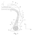
- the Fig.1 shows a partial cross-section through a low-section radial tire for passenger cars, which a profiled tread 1, consisting of two belt layers 2a, 2b, belt 2, which is covered by a bandage 18, a radial carcass 3, an airtight inner layer 4, side walls 6 as well as bead areas 5 of bead cores 7 and 8 apexes.
- the layers 2a, 2b of the belt 2 consist of embedded in a rubber compound reinforcements made of steel cord, which run parallel to each other within each layer, the steel cords of the layers are oriented in intersecting relation to the steel cords of the adjacent layer and each enclose an angle between 24 ° and 46 ° with the tire circumferential direction.
- the carcass ply 3 wraps around the bead areas 5 from axially inward to axially outward and ends in each case as a carcass turnup 3a at a height D, wherein D is arranged radially outward with respect to the bead area (above the bead area).
- the radial tire has an additional reinforcing reinforcement layer 9 reinforced with reinforcements, which is arranged axially on the outside of the carcass 3 in the side wall such that its lower end 10 lies below the first belt layer 2a at the level of the bead region 5 and its upper end 11 and axially bounded on the outside by the carcass turnup 3a. Between the carcass 3 and the additional reinforcing layer 9, a rubber layer 15 is arranged.
- This rubber layer 15 has over its radial extent an equal thickness, but tapers at its lower, the bead area facing end 16 from a height B triangular and ends in a tip 19.
- the thickness of the rubber layer 15 is greater than the thickness of the carcass high blow 3a arranged axially on the outside, wherein B lies at the level of the upper end of the bead region 5.
- This lower end of the rubber layer 16 is disposed axially inward with respect to the bead portion.
- the additional Reinforcing layer 9 starts at a height A, which lies between the heights E and B, wherein E is disposed at the level of the lower end of the bead core 7.
- the rubber layer 15 has at the height A a thickness of 0 - 2 mm, at the height B, a thickness of 0.5 - 3 mm, preferably a thickness of about 0.9 mm.
- A corresponds to the lower end of the additional reinforcement layer 10.
Landscapes
- Engineering & Computer Science (AREA)
- Mechanical Engineering (AREA)
- Tires In General (AREA)
Abstract
Description
- Die Erfindung betrifft einen Fahrzeugluftreifen mit Gürtellagen, mit zwei Seitenwänden, mit zwei Wulstbereichen mit wenigstens je einem Wulstkern, mit einer Karkasse, welche den Reifen von Wulstbereich zu Wulstbereich durchläuft, die Wulstbereiche von axial innen nach axial außen umschlingt und als Karkasshochschlag auf einer Höhe D endet, wobei D radial außen in Bezug auf den Wulstbereich angeordnet ist, mit einer Festigkeitsträger aufweisenden zusätzlichen Verstärkungslage, welche axial außen auf der Karkasse und derart in der Seitenwand angeordnet ist, dass deren unteres Ende auf Höhe des Wulstbereich und deren oberes Ende unterhalb einer Gürtellage liegt und mit einer Gummilage, welche zwischen der Karkasse und der zusätzlichen Verstärkungslage angeordnet ist.
- Ein derartiger Fahrzeugluftreifen ist beispielsweise in der bisher unveröffentlichten
DE 10 2003 109 582 A beschrieben. Zum Schutz vor Scheuerkontakten zwischen den Festigkeitsträgern der Karkasslage und denen der zusätzlichen Verstärkungslage ist eine Gummilage angeordnet. Hierdurch liegen beide Festigkeitsträger enthaltende Lagen nicht mehr unmittelbar aufeinander auf und es können nicht die Festigkeitsträger beider vorgenannter Lagen in unmittelbaren Kontakt kommen. Der untere Bereich der zusätzlichen Festigkeitsträgerlage ist zwischen Karkasslage und Wulstbereich angeordnet und endet vorzugsweise entweder auf Höhe des Apex, wobei das Ende zwischen Karkasslage und Apex liegt, oder endet axial innen oder axial außen in Bezug auf den Wulstkern oder unterhalb des Wulstkernes. Die Haltbarkeit des Fahrzeugluftreifens ist verbessert. Mit "Karkasslage" ist in derDE 10 2003 109 582 A in Bezug auf die Anordnung der zusätzlichen Verstärkungslage nicht der Karkasshochschlag gemeint. - Es hat sich jedoch gezeigt, dass weiterhin Verbesserungsbedarf hinsichtlich der Haltbarkeit des Fahrzeugluftreifens besteht.
- Es ist daher die Aufgabe der vorliegenden Erfindung, einen Fahrzeugluftreifen bereitzustellen, der in Bezug auf seine Haltbarkeit weiter verbessert ist.
- Die Aufgabe wird gelöst, indem diese Gummilage über ihre radiale Erstreckung eine gleiche Dicke aufweist, sich jedoch an ihrem unteren, dem Wulstbereich zugewandten Ende - im Reifenquerschnitt betrachtet - ab einer Höhe B dreieckförmig verjüngt und in einer Spitze endet, wobei B auf Höhe des oberen Endes des Wulstbereiches liegt, indem auf Höhe B die Dicke der Gummilage größer als die Dicke des axial außen angeordneten Karkasshochschlages ist und indem dieses untere Ende der Gummilage axial innen in Bezug auf den Wulstbereich angeordnet ist.
- Erfindungswesentlich ist, dass ein harmonischer Übergang zwischen den unterschiedlichen Lagen im Bereich des Wulstes geschaffen ist. Durch die sich an ihrem unteren Ende dreieckförmig verjüngende Gummilage sind Knicke der Karkasslage im Bereich des Wulstes vermieden und es treten keine Kraftspitzen im Wulstbereich auf. Zudem ist durch die Anordnung der Gummilage die Scherbelastung zwischen den Festigkeitsträger aufweisenden Lagen Karkasslage und Wulstverstärker verringert. Die Haltbarkeit des Fahrzeugreifens ist verbessert.
- "Wulstbereich" meint Wulstkern sowie Apex (Kernreiter), soweit dieser letztgenannte angeordnet ist.
"Höhe" meint die Höhe/ Erstreckung in radialer Richtung. - Vorteilhaft ist es, wenn jeder Wulstbereich nur aus einem Wulstkern besteht, wobei der Wulstkern vorzugsweise ein Hochkantkern ist. Es ist auf einen Apex verzichtet. Hochkantkerne haben einen Querschnitt, der höher als breit ist. Dementsprechend erstreckt sich der Kern den Wulstbereich hinauf. Hierdurch wird eine für die Reifenperformance vorteilhafte stärkere Kopplung zwischen Karkasse und Wulstverstärker erreicht. Diese stärkere Kopplung bewirkt jedoch auch eine stärkere Belastung im Wulstbereich zwischen Karkasse und Wulstverstärker. Diese stärkere Belastung, insbesondere Scherbelastung, ist durch die zusätzliche Gummilage verringert.
- In einer anderen Ausführung der Erfindung besteht der Wulstbereich aus Wulstkern und Apex. Ein Wulstkern, auf dem ein Apex angeordnet ist, weist einen etwa quadratischen Querschnitt auf. Ein quadratischer Wulstkern ist insbesondere für einen sicheren Felgensitz von Vorteil.
- Zweckmäßig ist es, wenn die zusätzliche Verstärkungslage auf einer Höhe A beginnt, welche zwischen den Höhen E und B liegt, wobei E auf Höhe des unteren Endes des Wulstkernes angeordnet ist. Es ist eine Staffelung der unterschiedlichen Lagenenden bewirkt, wodurch die Haltbarkeit des Reifens verbessert ist.
- Vorteilhaft ist es, wenn die Gummilage auf der Höhe A eine Dicke von 0 - 2 mm aufweist. Hierdurch erfolgt ein langsamer Materialaufbau der zusätzlichen Gummilage, wodurch einerseits die Karkasslage nicht geknickt angeordnet ist und wodurch andererseits nicht zu viel zusätzliches Material im Wulstbereich angeordnet ist, wodurch andernfalls unvorteilhaft viel Wärme gebildet wäre. Die Haltbarkeit des Reifens ist verbessert.
- Zweckmäßig ist es, wenn die Gummilage auf der Höhe B eine Dicke von 0,5 - 3 mm, vorzugsweise eine Dicke von etwa 0,9 mm aufweist. Die Gummilage radial oberhalb des Wulstbereiches puffert die Koppelung zwischen dem Wulstverstärker mit der Karkasse. Die vorgenannte gleichbleibende Dicke hat sich als besonders positiv für die verbesserte Haltbarkeit herausgestellt.
- Vorteilhaft ist es, wenn die Festigkeitsträger der Karkasse einen Winkel zwischen 78° und 90° mit der Reifenumfangsrichtung einschließen, wobei vorzugsweise die Festigkeitsträger des Wulstverstärkers einen Winkel zwischen 30° und 70°, vorzugsweise von etwa 55°, mit der Umfangsrichtung einschließen. Durch diese Winkelkonstellation ist die erwünschte Kopplung zwischen Karkasse und Wulstverstärkter am effektivsten.
- In bestimmten Ausführungen der Erfindung weist die Karkasse eine C-Lagenkonstruktion oder eine 1+0-Lagenkonstruktion auf. Bei einer 1+0-Lagenkonstruktion liegt das Karkasshochschlagende immer höher als das obere Apexende, wobei das Karkasshochschlagende mindestens 5mm höher als das obere Apexende endet.
- Vorteilhaft ist es, wenn die zusätzliche Verstärkungslage 1 - 40 mm, vorzugsweise etwa 25 mm weit unter den Gürtel reicht und dort endet, gemessen parallel zur Gürtelkontur und von der Gürtelkante der breitesten Gürtellage zur Gürtelmitte hin. Hierdurch ist das durch den Reifen im Fahrbetrieb gebildete Außengeräusch verringert. Denn es hat sich gezeigt, dass durch eine definierte Materialansammlung im Crown-Bereich des Reifens das Außengeräusch verbesserbar ist.
- Der erfindungsgemäße Fahrzeugluftreifen ist vorzugsweise ein PKW-Niederquerschnittsreifen. Die Seitenwände von Niederquerschnittsreifen werden aufgrund ihrer geringen Seitenwandhöhe besonders stark auf Biegung beansprucht. Um Ausfälle durch Risse bzw. Beschädigungen in der Seitenwand der eingangs genannten Art zu vermeiden, ist zur Verstärkung der Seitenwand zusätzlich zur zusätzlichen Verstärkungslage eine Gummilage mit spitz zulaufendem unteren Ende zwischen Karkasslage und dieser zusätzlichen Verstärkungslage eingebracht.
- Weitere Merkmale, Vorteile und Einzelheiten der Erfindung werden anhand der Zeichnung, die ein schematisches Ausführungsbeispiel darstellt, näher erläutert.
- Die
Fig.1 zeigt einen Teil-Querschnitt durch einen Niederquerschnitts-Radialreifen für Personenkraftwagen, welcher einen profilierten Laufstreifen 1, einen aus zwei Gürtellagen 2a, 2b, bestehenden Gürtel 2, welcher durch eine Bandage 18 abgedeckt ist, eine Radialkarkasse 3, eine luftdicht ausgeführte Innenschicht 4, Seitenwände 6 sowie Wulstbereiche 5 aus Wulstkernen 7 und Apexen 8 aufweist. Die Lagen 2a, 2b des Gürtels 2 bestehen aus in eine Gummimischung eingebetteten Festigkeitsträgern aus Stahlcord, welche innerhalb jeder Lage parallel zueinander verlaufen, wobei die Stahlcorde der Lagen in kreuzender Anordnung zu den Stahlcorden der benachbarten Lage orientiert sind und mit der Reifenumfangsrichtung jeweils einen Winkel zwischen 24° und 46° einschließen. - Die Karkasslage 3 umschlingt die Wulstbereiche 5 von axial innen nach axial außen und endet jeweils als Karkasshochschlag 3a auf einer Höhe D, wobei D radial außen in Bezug auf den Wulstbereich (oberhalb des Wulstbereiches) angeordnet ist. Der Radialreifen weist eine zusätzliche mit Festigkeitsträgern verstärkte Festigkeitsträgerlage 9 auf, welche axial außen auf der Karkasse 3 derart in der Seitenwand angeordnet ist, dass deren unteres Ende 10 auf Höhe des Wulstbereich 5 und deren oberes Ende 11 unterhalb der 1. Gürtellage 2a liegt und axial außen vom Karkasshochschlag 3a begrenzt wird. Zwischen der Karkasse 3 und der zusätzlichen Verstärkungslage 9 ist eine Gummilage 15 angeordnet. Diese Gummilage 15 weist über ihre radiale Erstreckung eine gleiche Dicke auf, verjüngt sich jedoch an ihrem unteren, dem Wulstbereich zugewandten Ende 16 ab einer Höhe B dreieckförmig und endet in einer Spitze 19. Auf Höhe B ist die Dicke der Gummilage 15 größer als die Dicke des axial außen angeordneten Karkasshochschlages 3a, wobei B auf Höhe des oberen Endes des Wulstbereiches 5 liegt. Dieses untere Ende der Gummilage 16 ist axial innen in Bezug auf den Wulstbereich angeordnet. Die zusätzliche
Verstärkungslage 9 beginnt auf einer Höhe A, welche zwischen den Höhen E und B liegt, wobei E auf Höhe des unteren Endes des Wulstkernes 7 angeordnet ist. Die Gummilage 15 weist auf der Höhe A eine Dicke von 0 - 2 mm auf, auf der Höhe B eine Dicke von 0,5 - 3 mm, vorzugsweise eine Dicke von etwa 0,9 mm. - A entspricht dem unteren Ende der zusätzlichen Festigkeitsträgerlage 10.
-
- 1
- Laufstreifen
- 2
- Gürtel
- 2a
- 1. Gürtellage
- 2b
- 2. Gürtellage
- 3
- Karkasse
- 3a
- Karkasshochschlag
- 4
- Innenschicht
- 5
- Wulstbereich
- 6
- Seitenwand
- 7
- Wulstkern
- 8
- Apex
- 9
- Zusätzliche Festigkeitsträgerlage
- 10
- Untere Ende der zusätzlichen Festigkeitsträgerlage
- 11
- Oberes Ende der zusätzlichen Festigkeitsträgerlage
- 15
- Gummilage
- 16
- Unteres Ende der Gummilage
- 18
- Bandage
- 19
- Spitze der Gummilage
- aR
- axiale Richtung
- rR
- radiale Richtung
Claims (10)
- Fahrzeugluftreifen mit Gürtellagen (2a, 2b),
mit zwei Seitenwänden,
mit zwei Wulstbereichen (5) mit wenigstens je einem Wulstkern (7),
mit einer Karkasse (3), welche den Reifen von Wulstbereich (5) zu Wulstbereich (5) durchläuft, die Wulstbereiche (5) von axial innen nach axial außen umschlingt und als Karkasshochschlag auf einer Höhe D endet, wobei D radial außen in Bezug auf den Wulstbereich angeordnet ist,
mit einer Festigkeitsträger aufweisenden zusätzlichen Verstärkungslage (9), welche axial außen auf der Karkasse (3) und derart in der Seitenwand (6) angeordnet ist, dass deren unteres Ende (10) auf Höhe des Wulstbereich (5) und deren oberes Ende (11) unterhalb einer Gürtellage (2a, 2b) liegt und
mit einer Gummilage (15), welche zwischen der Karkasse (3) und der zusätzlichen Verstärkungslage (9) angeordnet ist,
dadurch gekennzeichnet,
dass diese Gummilage (15) über ihre radiale Erstreckung eine gleiche Dicke aufweist, sich jedoch an ihrem unteren, dem Wulstbereich zugewandten Ende (16) - im Reifenquerschnitt betrachtet - ab einer Höhe B dreieckförmig verjüngt und in einer Spitze (19) endet,
dass auf Höhe B die Dicke der Gummilage (15) größer als die Dicke des axial außen angeordneten Karkasshochschlages (3a) ist, wobei B auf Höhe des oberen Endes des Wulstbereiches liegt und
dass dieses untere Ende (16) der Gummilage axial innen in Bezug auf den Wulstbereich (5) angeordnet ist. - Fahrzeugluftreifen nach Anspruch 1,
dadurch gekennzeichnet, dass jeder Wulstbereich (5) nur aus einem Wulstkern (7) besteht, wobei der Wulstkern (7) vorzugsweise ein Hochkantkern ist. - Fahrzeugluftreifen nach Anspruch 1,
dadurch gekennzeichnet, dass der Wulstbereich (5) aus Wulstkern (7) und Apex (8) besteht. - Fahrzeugluftreifen nach einem oder mehreren der vorangehenden Ansprüche,
dadurch gekennzeichnet, dass die zusätzliche Verstärkungslage (9) auf einer Höhe A beginnt, welche zwischen den Höhen E und B liegt, wobei E auf Höhe des unteren Endes des Wulstkernes (7) angeordnet ist. - Fahrzeugluftreifen nach einem oder mehreren der vorangehenden Ansprüche,
dadurch gekennzeichnet, dass die Gummilage (15) auf der Höhe A eine Dicke von 0 - 2 mm aufweist. - Fahrzeugluftreifen nach einem oder mehreren der vorangehenden Ansprüche,
dadurch gekennzeichnet, dass die Gummilage (15) auf der Höhe B eine Dicke von 0,5 - 3 mm, vorzugsweise eine Dicke von etwa 0,9 mm aufweist. - Fahrzeugluftreifen nach einem oder mehreren der vorangehenden Ansprüche,
dadurch gekennzeichnet, dass die Festigkeitsträger der Karkasse (3) einen Winkel zwischen 78° und 90° mit der Reifenumfangsrichtung einschließen. - Fahrzeugluftreifen nach einem oder mehreren der vorangehenden Ansprüche,
dadurch gekennzeichnet, dass die Karkasse (3) eine C-Lagenkonstruktion oder eine 1+0-Lagenkonstruktion aufweist. - Fahrzeugluftreifen nach einem oder mehreren der vorangehenden Ansprüche,
dadurch gekennzeichnet, dass die zusätzliche Verstärkungslage (9) 1 - 40 mm, vorzugsweise etwa 25 mm weit unter den Gürtel (2) reicht und dort endet, gemessen parallel zur Gürtelkontur und von der Gürtelkante der breitesten Gürtellage (2a, 2b) zur Gürtelmitte. - Fahrzeugluftreifen nach einem oder mehreren der vorangehenden Ansprüche,
dadurch gekennzeichnet, dass dieser ein PKW-Niederquerschnittsreifen ist.
Applications Claiming Priority (1)
| Application Number | Priority Date | Filing Date | Title |
|---|---|---|---|
| DE102013225157.2A DE102013225157A1 (de) | 2013-12-06 | 2013-12-06 | Fahrzeugluftreifen |
Publications (3)
| Publication Number | Publication Date |
|---|---|
| EP2889161A2 true EP2889161A2 (de) | 2015-07-01 |
| EP2889161A3 EP2889161A3 (de) | 2015-07-22 |
| EP2889161B1 EP2889161B1 (de) | 2019-04-03 |
Family
ID=51845338
Family Applications (1)
| Application Number | Title | Priority Date | Filing Date |
|---|---|---|---|
| EP14191526.4A Active EP2889161B1 (de) | 2013-12-06 | 2014-11-03 | Fahrzeugluftreifen |
Country Status (3)
| Country | Link |
|---|---|
| EP (1) | EP2889161B1 (de) |
| DE (1) | DE102013225157A1 (de) |
| ES (1) | ES2729334T3 (de) |
Family Cites Families (4)
| Publication number | Priority date | Publication date | Assignee | Title |
|---|---|---|---|---|
| IT1039990B (it) * | 1975-07-23 | 1979-12-10 | Pirelli | Perfezionamento ai talloni di pneumatici a carcassa radiale |
| US20070044889A1 (en) * | 2005-09-01 | 2007-03-01 | Bridgestone Firestone North American Tire, Llc | Tire having a sidewall reinforcement |
| DE102005041937A1 (de) * | 2005-09-03 | 2007-03-08 | Continental Aktiengesellschaft | Fahrzeugluftreifen und Verfahren zur Herstellung |
| DE102006025794A1 (de) * | 2006-06-02 | 2007-12-06 | Continental Aktiengesellschaft | Fahrzeugluftreifen mit Notlaufeigenschaften |
-
2013
- 2013-12-06 DE DE102013225157.2A patent/DE102013225157A1/de not_active Withdrawn
-
2014
- 2014-11-03 EP EP14191526.4A patent/EP2889161B1/de active Active
- 2014-11-03 ES ES14191526T patent/ES2729334T3/es active Active
Also Published As
| Publication number | Publication date |
|---|---|
| EP2889161A3 (de) | 2015-07-22 |
| DE102013225157A1 (de) | 2015-06-11 |
| ES2729334T3 (es) | 2019-10-31 |
| EP2889161B1 (de) | 2019-04-03 |
Similar Documents
| Publication | Publication Date | Title |
|---|---|---|
| DE69828584T2 (de) | Radialreifen für schwerfahrzeuge | |
| DE3126571C2 (de) | Luftreifen in Radialbauart | |
| DE69918031T2 (de) | Luftreifen | |
| DE2436115A1 (de) | Fahrzeugluftreifen | |
| DE60207856T2 (de) | Reifen mit verstärktem wulst | |
| EP2627523B1 (de) | Fahrzeugluftreifen | |
| EP1970221B1 (de) | Fahrzeugluftreifen mit Notlaufeigenschaften | |
| DE60113321T2 (de) | Luftreifen | |
| EP3088209B1 (de) | Fahrzeugluftreifen | |
| WO2007141073A1 (de) | Fahrzeugluftreifen mit notlaufeigenschaften | |
| EP3166804B1 (de) | Nutzfahrzeugreifen | |
| EP2740615B1 (de) | Fahrzeugluftreifen | |
| DE60132917T2 (de) | Fahrzeugluftreifen mit einem konzentrisch zum reifen angerordneten ring | |
| DE60117070T2 (de) | Luftreifen mit asymmetrischer Gürtelstruktur und Verfahren zum Aufziehen eines Reifens auf einem Fahrzeug | |
| EP2889161B1 (de) | Fahrzeugluftreifen | |
| EP2979905B1 (de) | Fahrzeugluftreifen | |
| EP3395590B1 (de) | Fahrzeugluftreifen | |
| EP3041690B1 (de) | Fahrzeugluftreifen | |
| DE2525078A1 (de) | Fahrzeugluftreifen, insbesondere fuer lastkraftwagen | |
| WO2005044596A1 (de) | Fahrzeugluftreifen | |
| EP2808177A1 (de) | Fahrzeugluftreifen mit Notlaufeigenschaften | |
| DE102014207193A1 (de) | Fahrzeugluftreifen | |
| DE602004013173T2 (de) | Notlaufreifen mit getrennten Karkasslagen im Kronenbereich | |
| EP2078622B1 (de) | Fahrzeugluftreifen | |
| WO2009053132A1 (de) | Fahrzeugluftreifen mit notlaufeigenschaften |
Legal Events
| Date | Code | Title | Description |
|---|---|---|---|
| PUAL | Search report despatched |
Free format text: ORIGINAL CODE: 0009013 |
|
| PUAI | Public reference made under article 153(3) epc to a published international application that has entered the european phase |
Free format text: ORIGINAL CODE: 0009012 |
|
| 17P | Request for examination filed |
Effective date: 20141103 |
|
| AK | Designated contracting states |
Kind code of ref document: A2 Designated state(s): AL AT BE BG CH CY CZ DE DK EE ES FI FR GB GR HR HU IE IS IT LI LT LU LV MC MK MT NL NO PL PT RO RS SE SI SK SM TR |
|
| AX | Request for extension of the european patent |
Extension state: BA ME |
|
| AK | Designated contracting states |
Kind code of ref document: A3 Designated state(s): AL AT BE BG CH CY CZ DE DK EE ES FI FR GB GR HR HU IE IS IT LI LT LU LV MC MK MT NL NO PL PT RO RS SE SI SK SM TR |
|
| AX | Request for extension of the european patent |
Extension state: BA ME |
|
| RIC1 | Information provided on ipc code assigned before grant |
Ipc: B60C 15/06 20060101ALI20150612BHEP Ipc: B60C 15/00 20060101AFI20150612BHEP |
|
| R17P | Request for examination filed (corrected) |
Effective date: 20160122 |
|
| RBV | Designated contracting states (corrected) |
Designated state(s): AL AT BE BG CH CY CZ DE DK EE ES FI FR GB GR HR HU IE IS IT LI LT LU LV MC MK MT NL NO PL PT RO RS SE SI SK SM TR |
|
| RIC1 | Information provided on ipc code assigned before grant |
Ipc: B60C 15/00 20060101AFI20180911BHEP Ipc: B60C 15/06 20060101ALI20180911BHEP Ipc: B60C 13/04 20060101ALI20180911BHEP Ipc: B60C 13/00 20060101ALN20180911BHEP |
|
| GRAP | Despatch of communication of intention to grant a patent |
Free format text: ORIGINAL CODE: EPIDOSNIGR1 |
|
| STAA | Information on the status of an ep patent application or granted ep patent |
Free format text: STATUS: GRANT OF PATENT IS INTENDED |
|
| RIC1 | Information provided on ipc code assigned before grant |
Ipc: B60C 15/06 20060101ALI20181024BHEP Ipc: B60C 13/04 20060101ALI20181024BHEP Ipc: B60C 13/00 20060101ALN20181024BHEP Ipc: B60C 15/00 20060101AFI20181024BHEP |
|
| INTG | Intention to grant announced |
Effective date: 20181109 |
|
| GRAS | Grant fee paid |
Free format text: ORIGINAL CODE: EPIDOSNIGR3 |
|
| GRAA | (expected) grant |
Free format text: ORIGINAL CODE: 0009210 |
|
| STAA | Information on the status of an ep patent application or granted ep patent |
Free format text: STATUS: THE PATENT HAS BEEN GRANTED |
|
| AK | Designated contracting states |
Kind code of ref document: B1 Designated state(s): AL AT BE BG CH CY CZ DE DK EE ES FI FR GB GR HR HU IE IS IT LI LT LU LV MC MK MT NL NO PL PT RO RS SE SI SK SM TR |
|
| REG | Reference to a national code |
Ref country code: GB Ref legal event code: FG4D Free format text: NOT ENGLISH |
|
| REG | Reference to a national code |
Ref country code: CH Ref legal event code: EP Ref country code: AT Ref legal event code: REF Ref document number: 1115255 Country of ref document: AT Kind code of ref document: T Effective date: 20190415 |
|
| REG | Reference to a national code |
Ref country code: DE Ref legal event code: R096 Ref document number: 502014011294 Country of ref document: DE |
|
| REG | Reference to a national code |
Ref country code: IE Ref legal event code: FG4D Free format text: LANGUAGE OF EP DOCUMENT: GERMAN |
|
| REG | Reference to a national code |
Ref country code: NL Ref legal event code: MP Effective date: 20190403 |
|
| REG | Reference to a national code |
Ref country code: LT Ref legal event code: MG4D |
|
| PG25 | Lapsed in a contracting state [announced via postgrant information from national office to epo] |
Ref country code: NL Free format text: LAPSE BECAUSE OF FAILURE TO SUBMIT A TRANSLATION OF THE DESCRIPTION OR TO PAY THE FEE WITHIN THE PRESCRIBED TIME-LIMIT Effective date: 20190403 |
|
| PG25 | Lapsed in a contracting state [announced via postgrant information from national office to epo] |
Ref country code: HR Free format text: LAPSE BECAUSE OF FAILURE TO SUBMIT A TRANSLATION OF THE DESCRIPTION OR TO PAY THE FEE WITHIN THE PRESCRIBED TIME-LIMIT Effective date: 20190403 Ref country code: LT Free format text: LAPSE BECAUSE OF FAILURE TO SUBMIT A TRANSLATION OF THE DESCRIPTION OR TO PAY THE FEE WITHIN THE PRESCRIBED TIME-LIMIT Effective date: 20190403 Ref country code: NO Free format text: LAPSE BECAUSE OF FAILURE TO SUBMIT A TRANSLATION OF THE DESCRIPTION OR TO PAY THE FEE WITHIN THE PRESCRIBED TIME-LIMIT Effective date: 20190703 Ref country code: SE Free format text: LAPSE BECAUSE OF FAILURE TO SUBMIT A TRANSLATION OF THE DESCRIPTION OR TO PAY THE FEE WITHIN THE PRESCRIBED TIME-LIMIT Effective date: 20190403 Ref country code: FI Free format text: LAPSE BECAUSE OF FAILURE TO SUBMIT A TRANSLATION OF THE DESCRIPTION OR TO PAY THE FEE WITHIN THE PRESCRIBED TIME-LIMIT Effective date: 20190403 Ref country code: CZ Free format text: LAPSE BECAUSE OF FAILURE TO SUBMIT A TRANSLATION OF THE DESCRIPTION OR TO PAY THE FEE WITHIN THE PRESCRIBED TIME-LIMIT Effective date: 20190403 Ref country code: AL Free format text: LAPSE BECAUSE OF FAILURE TO SUBMIT A TRANSLATION OF THE DESCRIPTION OR TO PAY THE FEE WITHIN THE PRESCRIBED TIME-LIMIT Effective date: 20190403 Ref country code: PT Free format text: LAPSE BECAUSE OF FAILURE TO SUBMIT A TRANSLATION OF THE DESCRIPTION OR TO PAY THE FEE WITHIN THE PRESCRIBED TIME-LIMIT Effective date: 20190803 |
|
| REG | Reference to a national code |
Ref country code: ES Ref legal event code: FG2A Ref document number: 2729334 Country of ref document: ES Kind code of ref document: T3 Effective date: 20191031 |
|
| PG25 | Lapsed in a contracting state [announced via postgrant information from national office to epo] |
Ref country code: GR Free format text: LAPSE BECAUSE OF FAILURE TO SUBMIT A TRANSLATION OF THE DESCRIPTION OR TO PAY THE FEE WITHIN THE PRESCRIBED TIME-LIMIT Effective date: 20190704 Ref country code: BG Free format text: LAPSE BECAUSE OF FAILURE TO SUBMIT A TRANSLATION OF THE DESCRIPTION OR TO PAY THE FEE WITHIN THE PRESCRIBED TIME-LIMIT Effective date: 20190703 Ref country code: LV Free format text: LAPSE BECAUSE OF FAILURE TO SUBMIT A TRANSLATION OF THE DESCRIPTION OR TO PAY THE FEE WITHIN THE PRESCRIBED TIME-LIMIT Effective date: 20190403 Ref country code: RS Free format text: LAPSE BECAUSE OF FAILURE TO SUBMIT A TRANSLATION OF THE DESCRIPTION OR TO PAY THE FEE WITHIN THE PRESCRIBED TIME-LIMIT Effective date: 20190403 Ref country code: PL Free format text: LAPSE BECAUSE OF FAILURE TO SUBMIT A TRANSLATION OF THE DESCRIPTION OR TO PAY THE FEE WITHIN THE PRESCRIBED TIME-LIMIT Effective date: 20190403 |
|
| PG25 | Lapsed in a contracting state [announced via postgrant information from national office to epo] |
Ref country code: IS Free format text: LAPSE BECAUSE OF FAILURE TO SUBMIT A TRANSLATION OF THE DESCRIPTION OR TO PAY THE FEE WITHIN THE PRESCRIBED TIME-LIMIT Effective date: 20190803 |
|
| REG | Reference to a national code |
Ref country code: DE Ref legal event code: R097 Ref document number: 502014011294 Country of ref document: DE |
|
| PG25 | Lapsed in a contracting state [announced via postgrant information from national office to epo] |
Ref country code: EE Free format text: LAPSE BECAUSE OF FAILURE TO SUBMIT A TRANSLATION OF THE DESCRIPTION OR TO PAY THE FEE WITHIN THE PRESCRIBED TIME-LIMIT Effective date: 20190403 Ref country code: DK Free format text: LAPSE BECAUSE OF FAILURE TO SUBMIT A TRANSLATION OF THE DESCRIPTION OR TO PAY THE FEE WITHIN THE PRESCRIBED TIME-LIMIT Effective date: 20190403 Ref country code: RO Free format text: LAPSE BECAUSE OF FAILURE TO SUBMIT A TRANSLATION OF THE DESCRIPTION OR TO PAY THE FEE WITHIN THE PRESCRIBED TIME-LIMIT Effective date: 20190403 Ref country code: SK Free format text: LAPSE BECAUSE OF FAILURE TO SUBMIT A TRANSLATION OF THE DESCRIPTION OR TO PAY THE FEE WITHIN THE PRESCRIBED TIME-LIMIT Effective date: 20190403 |
|
| PLBE | No opposition filed within time limit |
Free format text: ORIGINAL CODE: 0009261 |
|
| STAA | Information on the status of an ep patent application or granted ep patent |
Free format text: STATUS: NO OPPOSITION FILED WITHIN TIME LIMIT |
|
| PG25 | Lapsed in a contracting state [announced via postgrant information from national office to epo] |
Ref country code: SM Free format text: LAPSE BECAUSE OF FAILURE TO SUBMIT A TRANSLATION OF THE DESCRIPTION OR TO PAY THE FEE WITHIN THE PRESCRIBED TIME-LIMIT Effective date: 20190403 |
|
| 26N | No opposition filed |
Effective date: 20200106 |
|
| PG25 | Lapsed in a contracting state [announced via postgrant information from national office to epo] |
Ref country code: TR Free format text: LAPSE BECAUSE OF FAILURE TO SUBMIT A TRANSLATION OF THE DESCRIPTION OR TO PAY THE FEE WITHIN THE PRESCRIBED TIME-LIMIT Effective date: 20190403 |
|
| PG25 | Lapsed in a contracting state [announced via postgrant information from national office to epo] |
Ref country code: SI Free format text: LAPSE BECAUSE OF FAILURE TO SUBMIT A TRANSLATION OF THE DESCRIPTION OR TO PAY THE FEE WITHIN THE PRESCRIBED TIME-LIMIT Effective date: 20190403 |
|
| REG | Reference to a national code |
Ref country code: CH Ref legal event code: PL |
|
| PG25 | Lapsed in a contracting state [announced via postgrant information from national office to epo] |
Ref country code: LI Free format text: LAPSE BECAUSE OF NON-PAYMENT OF DUE FEES Effective date: 20191130 Ref country code: CH Free format text: LAPSE BECAUSE OF NON-PAYMENT OF DUE FEES Effective date: 20191130 Ref country code: LU Free format text: LAPSE BECAUSE OF NON-PAYMENT OF DUE FEES Effective date: 20191103 Ref country code: MC Free format text: LAPSE BECAUSE OF FAILURE TO SUBMIT A TRANSLATION OF THE DESCRIPTION OR TO PAY THE FEE WITHIN THE PRESCRIBED TIME-LIMIT Effective date: 20190403 |
|
| REG | Reference to a national code |
Ref country code: BE Ref legal event code: MM Effective date: 20191130 |
|
| GBPC | Gb: european patent ceased through non-payment of renewal fee |
Effective date: 20191103 |
|
| PG25 | Lapsed in a contracting state [announced via postgrant information from national office to epo] |
Ref country code: GB Free format text: LAPSE BECAUSE OF NON-PAYMENT OF DUE FEES Effective date: 20191103 Ref country code: FR Free format text: LAPSE BECAUSE OF NON-PAYMENT OF DUE FEES Effective date: 20191130 Ref country code: IE Free format text: LAPSE BECAUSE OF NON-PAYMENT OF DUE FEES Effective date: 20191103 |
|
| PG25 | Lapsed in a contracting state [announced via postgrant information from national office to epo] |
Ref country code: BE Free format text: LAPSE BECAUSE OF NON-PAYMENT OF DUE FEES Effective date: 20191130 |
|
| REG | Reference to a national code |
Ref country code: AT Ref legal event code: MM01 Ref document number: 1115255 Country of ref document: AT Kind code of ref document: T Effective date: 20191103 |
|
| PG25 | Lapsed in a contracting state [announced via postgrant information from national office to epo] |
Ref country code: AT Free format text: LAPSE BECAUSE OF NON-PAYMENT OF DUE FEES Effective date: 20191103 |
|
| PG25 | Lapsed in a contracting state [announced via postgrant information from national office to epo] |
Ref country code: CY Free format text: LAPSE BECAUSE OF FAILURE TO SUBMIT A TRANSLATION OF THE DESCRIPTION OR TO PAY THE FEE WITHIN THE PRESCRIBED TIME-LIMIT Effective date: 20190403 |
|
| PG25 | Lapsed in a contracting state [announced via postgrant information from national office to epo] |
Ref country code: HU Free format text: LAPSE BECAUSE OF FAILURE TO SUBMIT A TRANSLATION OF THE DESCRIPTION OR TO PAY THE FEE WITHIN THE PRESCRIBED TIME-LIMIT; INVALID AB INITIO Effective date: 20141103 Ref country code: MT Free format text: LAPSE BECAUSE OF FAILURE TO SUBMIT A TRANSLATION OF THE DESCRIPTION OR TO PAY THE FEE WITHIN THE PRESCRIBED TIME-LIMIT Effective date: 20190403 |
|
| PG25 | Lapsed in a contracting state [announced via postgrant information from national office to epo] |
Ref country code: MK Free format text: LAPSE BECAUSE OF FAILURE TO SUBMIT A TRANSLATION OF THE DESCRIPTION OR TO PAY THE FEE WITHIN THE PRESCRIBED TIME-LIMIT Effective date: 20190403 |
|
| REG | Reference to a national code |
Ref country code: DE Ref legal event code: R081 Ref document number: 502014011294 Country of ref document: DE Owner name: CONTINENTAL REIFEN DEUTSCHLAND GMBH, DE Free format text: FORMER OWNER: CONTINENTAL REIFEN DEUTSCHLAND GMBH, 30165 HANNOVER, DE |
|
| PGFP | Annual fee paid to national office [announced via postgrant information from national office to epo] |
Ref country code: IT Payment date: 20241126 Year of fee payment: 11 Ref country code: ES Payment date: 20241230 Year of fee payment: 11 |
|
| PGFP | Annual fee paid to national office [announced via postgrant information from national office to epo] |
Ref country code: DE Payment date: 20251130 Year of fee payment: 12 |