EP2887429A1 - Sekundärbatterie und Sekundärbatteriemodul - Google Patents
Sekundärbatterie und Sekundärbatteriemodul Download PDFInfo
- Publication number
- EP2887429A1 EP2887429A1 EP14167283.2A EP14167283A EP2887429A1 EP 2887429 A1 EP2887429 A1 EP 2887429A1 EP 14167283 A EP14167283 A EP 14167283A EP 2887429 A1 EP2887429 A1 EP 2887429A1
- Authority
- EP
- European Patent Office
- Prior art keywords
- terminal
- plate
- secondary battery
- terminal plate
- guide element
- Prior art date
- Legal status (The legal status is an assumption and is not a legal conclusion. Google has not performed a legal analysis and makes no representation as to the accuracy of the status listed.)
- Granted
Links
Images


Classifications
-
- H—ELECTRICITY
- H01—ELECTRIC ELEMENTS
- H01M—PROCESSES OR MEANS, e.g. BATTERIES, FOR THE DIRECT CONVERSION OF CHEMICAL ENERGY INTO ELECTRICAL ENERGY
- H01M50/00—Constructional details or processes of manufacture of the non-active parts of electrochemical cells other than fuel cells, e.g. hybrid cells
- H01M50/50—Current conducting connections for cells or batteries
- H01M50/528—Fixed electrical connections, i.e. not intended for disconnection
-
- H—ELECTRICITY
- H01—ELECTRIC ELEMENTS
- H01M—PROCESSES OR MEANS, e.g. BATTERIES, FOR THE DIRECT CONVERSION OF CHEMICAL ENERGY INTO ELECTRICAL ENERGY
- H01M10/00—Secondary cells; Manufacture thereof
- H01M10/04—Construction or manufacture in general
- H01M10/0413—Large-sized flat cells or batteries for motive or stationary systems with plate-like electrodes
-
- H—ELECTRICITY
- H01—ELECTRIC ELEMENTS
- H01M—PROCESSES OR MEANS, e.g. BATTERIES, FOR THE DIRECT CONVERSION OF CHEMICAL ENERGY INTO ELECTRICAL ENERGY
- H01M10/00—Secondary cells; Manufacture thereof
- H01M10/04—Construction or manufacture in general
- H01M10/0436—Small-sized flat cells or batteries for portable equipment
-
- H—ELECTRICITY
- H01—ELECTRIC ELEMENTS
- H01M—PROCESSES OR MEANS, e.g. BATTERIES, FOR THE DIRECT CONVERSION OF CHEMICAL ENERGY INTO ELECTRICAL ENERGY
- H01M50/00—Constructional details or processes of manufacture of the non-active parts of electrochemical cells other than fuel cells, e.g. hybrid cells
- H01M50/50—Current conducting connections for cells or batteries
- H01M50/502—Interconnectors for connecting terminals of adjacent batteries; Interconnectors for connecting cells outside a battery casing
- H01M50/507—Interconnectors for connecting terminals of adjacent batteries; Interconnectors for connecting cells outside a battery casing comprising an arrangement of two or more busbars within a container structure, e.g. busbar modules
-
- H—ELECTRICITY
- H01—ELECTRIC ELEMENTS
- H01M—PROCESSES OR MEANS, e.g. BATTERIES, FOR THE DIRECT CONVERSION OF CHEMICAL ENERGY INTO ELECTRICAL ENERGY
- H01M50/00—Constructional details or processes of manufacture of the non-active parts of electrochemical cells other than fuel cells, e.g. hybrid cells
- H01M50/50—Current conducting connections for cells or batteries
- H01M50/502—Interconnectors for connecting terminals of adjacent batteries; Interconnectors for connecting cells outside a battery casing
- H01M50/514—Methods for interconnecting adjacent batteries or cells
- H01M50/516—Methods for interconnecting adjacent batteries or cells by welding, soldering or brazing
-
- H—ELECTRICITY
- H01—ELECTRIC ELEMENTS
- H01M—PROCESSES OR MEANS, e.g. BATTERIES, FOR THE DIRECT CONVERSION OF CHEMICAL ENERGY INTO ELECTRICAL ENERGY
- H01M50/00—Constructional details or processes of manufacture of the non-active parts of electrochemical cells other than fuel cells, e.g. hybrid cells
- H01M50/50—Current conducting connections for cells or batteries
- H01M50/502—Interconnectors for connecting terminals of adjacent batteries; Interconnectors for connecting cells outside a battery casing
- H01M50/521—Interconnectors for connecting terminals of adjacent batteries; Interconnectors for connecting cells outside a battery casing characterised by the material
- H01M50/522—Inorganic material
-
- H—ELECTRICITY
- H01—ELECTRIC ELEMENTS
- H01M—PROCESSES OR MEANS, e.g. BATTERIES, FOR THE DIRECT CONVERSION OF CHEMICAL ENERGY INTO ELECTRICAL ENERGY
- H01M50/00—Constructional details or processes of manufacture of the non-active parts of electrochemical cells other than fuel cells, e.g. hybrid cells
- H01M50/50—Current conducting connections for cells or batteries
- H01M50/543—Terminals
- H01M50/547—Terminals characterised by the disposition of the terminals on the cells
- H01M50/55—Terminals characterised by the disposition of the terminals on the cells on the same side of the cell
-
- H—ELECTRICITY
- H01—ELECTRIC ELEMENTS
- H01M—PROCESSES OR MEANS, e.g. BATTERIES, FOR THE DIRECT CONVERSION OF CHEMICAL ENERGY INTO ELECTRICAL ENERGY
- H01M50/00—Constructional details or processes of manufacture of the non-active parts of electrochemical cells other than fuel cells, e.g. hybrid cells
- H01M50/50—Current conducting connections for cells or batteries
- H01M50/543—Terminals
- H01M50/552—Terminals characterised by their shape
- H01M50/553—Terminals adapted for prismatic, pouch or rectangular cells
-
- H—ELECTRICITY
- H01—ELECTRIC ELEMENTS
- H01M—PROCESSES OR MEANS, e.g. BATTERIES, FOR THE DIRECT CONVERSION OF CHEMICAL ENERGY INTO ELECTRICAL ENERGY
- H01M50/00—Constructional details or processes of manufacture of the non-active parts of electrochemical cells other than fuel cells, e.g. hybrid cells
- H01M50/50—Current conducting connections for cells or batteries
- H01M50/543—Terminals
- H01M50/562—Terminals characterised by the material
-
- H—ELECTRICITY
- H01—ELECTRIC ELEMENTS
- H01M—PROCESSES OR MEANS, e.g. BATTERIES, FOR THE DIRECT CONVERSION OF CHEMICAL ENERGY INTO ELECTRICAL ENERGY
- H01M50/00—Constructional details or processes of manufacture of the non-active parts of electrochemical cells other than fuel cells, e.g. hybrid cells
- H01M50/50—Current conducting connections for cells or batteries
- H01M50/543—Terminals
- H01M50/564—Terminals characterised by their manufacturing process
- H01M50/566—Terminals characterised by their manufacturing process by welding, soldering or brazing
-
- Y—GENERAL TAGGING OF NEW TECHNOLOGICAL DEVELOPMENTS; GENERAL TAGGING OF CROSS-SECTIONAL TECHNOLOGIES SPANNING OVER SEVERAL SECTIONS OF THE IPC; TECHNICAL SUBJECTS COVERED BY FORMER USPC CROSS-REFERENCE ART COLLECTIONS [XRACs] AND DIGESTS
- Y02—TECHNOLOGIES OR APPLICATIONS FOR MITIGATION OR ADAPTATION AGAINST CLIMATE CHANGE
- Y02E—REDUCTION OF GREENHOUSE GAS [GHG] EMISSIONS, RELATED TO ENERGY GENERATION, TRANSMISSION OR DISTRIBUTION
- Y02E60/00—Enabling technologies; Technologies with a potential or indirect contribution to GHG emissions mitigation
- Y02E60/10—Energy storage using batteries
-
- Y—GENERAL TAGGING OF NEW TECHNOLOGICAL DEVELOPMENTS; GENERAL TAGGING OF CROSS-SECTIONAL TECHNOLOGIES SPANNING OVER SEVERAL SECTIONS OF THE IPC; TECHNICAL SUBJECTS COVERED BY FORMER USPC CROSS-REFERENCE ART COLLECTIONS [XRACs] AND DIGESTS
- Y02—TECHNOLOGIES OR APPLICATIONS FOR MITIGATION OR ADAPTATION AGAINST CLIMATE CHANGE
- Y02P—CLIMATE CHANGE MITIGATION TECHNOLOGIES IN THE PRODUCTION OR PROCESSING OF GOODS
- Y02P70/00—Climate change mitigation technologies in the production process for final industrial or consumer products
- Y02P70/50—Manufacturing or production processes characterised by the final manufactured product
Definitions
- the present invention relates to a secondary battery comprising an electrode assembly and a terminal that is electrically connected to the electrode assembly. Furthermore, the invention relates to a secondary battery module comprising a plurality of secondary batteries, wherein one terminal of one of the batteries is connected one terminal of an another one of the batteries that is adjacent to the one of the batteries by a bus bar.
- secondary batteries are rechargeable, and the use of second batteries is encouraged owing to economical and eco-friendly aspects thereof.
- a contact element e.g. to a bus bar
- the terminal is provided with a terminal plate, which comprises a first part and a second part, wherein the first part is formed of a first material and the second part is formed of a second material that differs from the first material.
- the object is achieved according to the invention in that at least one of the batteries is a battery according to the invention.
- the first and the second material may be chosen based on their respective welding properties in order to facilitate welding of the terminal to the contact element and to the electrode assembly, e.g. when assembling the battery. Interconnecting the first and the second parts may be performed before assembling the battery starts without affecting the assembling of the battery starts.
- the material of the second part may be chosen to facilitate welding the second part to the contact element.
- the second part material and the contact element material may therefore be similar or same materials.
- the first part and the second part may at least sectionwise abut a contact plane.
- the contact plane may be a common contact plane of the first and the second parts and may serve as a rest for the contact element, e.g. the bus bar. Hence, no protruding parts of the terminal plate obstruct the placement of the contact element onto the terminal plate prior to welding the contact element to the terminal plate.
- the contact element can abut the contact plane extensively, providing for a good welding and electrical contact.
- the terminal plate is preferably formed continuously, i.e. as a single part, of the first and the second parts in order to minimize internal electrical resistance of the terminal plate.
- an insulator may be arranged between the terminal plate and a cap plate of the battery in order to avoid an unintended electrical contact between the terminal plate and the cap plate.
- a gap is preferably formed between the terminal plate and the insulator, such that heat caused by welding of the contact element precisely to the terminal plate can be dissipated and does not overheat the insulator.
- the second part can comprise a guide element, against which the contact element can be placed before welding the contact element to the terminal plate.
- the welding position of the other contact element can be predetermined by the guide element that can act as a stop for the contact element at least in one direction. A precise positioning of the contact element is thus facilitated.
- the second part may comprise the guide element and a protrusion that is provided at a distance from the guide element, the guide element and the protrusion extending in the same direction.
- the guide element and the protrusion thus restrict movements of the contact element in two opposite directions and form a positioning channel for the contact element, hence further facilitate placing the contact element precisely onto the terminal plate.
- the guide element and the protrusion are preferably formed of the same material, e. g. the second material, such that the second part can be easily formed as a single part, e.g. completely of the second material and for instance by milling or stamping and bending.
- the terminal may comprise a collector that interconnects the terminal plate and the electrode assembly.
- the first part of the terminal plate and the collector may be formed of the same material, such that the first part and the collector can be easily formed as a single part, e.g. completely of the second material and for instance by stamping and bending. Furthermore, the first part may be affixed to the collector, for instance by welding.
- the collector material may be chosen to facilitate welding of the collector to an electrode of the electrode assembly.
- the collector and the electrode may be formed of similar or same materials.
- the battery can comprise another terminal, whose terminal plate is formed of and may even be formed completely or consist of the first material.
- This other terminal can be easily formed as a single part, e.g. completely of one material and for instance by stamping and bending, and may be easily weldable to the electrode assembly and in particular to another electrode of the electrode assembly as the terminal mentioned before and to another contact element.
- An insulator e. g. another insulator, may be arranged between the other terminal plate and the cap plate of the battery in order to avoid an unintended electrical contact between the other terminal plate and the cap plate.
- a gap may be formed between the other terminal plate and the insulator, such that heat caused by welding of another contact element to the other terminal plate can be dissipated and does not overheat the insulator.
- the terminal plate of the other terminal comprises a guide element, against which the other contact element can be placed before welding the other contact element to the other terminal plate.
- the welding position of the other contact element can be predetermined by the guide element that can act as a stop for the other contact element at least in one direction. A precise positioning of the other contact element is thus facilitated
- the terminal plate of the other terminal can comprise the guide element and a protrusion that is provided at a distance from the guide element, the guide element and the protrusion extending in the same direction.
- the guide element and the protrusion thus restrict movements of the other contact element in two opposite directions and form a positioning channel for the other contact element, hence further facilitate placing the other contact element precisely onto the terminal plate.
- the guide element and the protrusion are preferably formed of the same material, such that the other terminal with the guide element and the protrusion can be easily formed as a single part, e.g. completely of one material and for instance by milling or stamping and bending.
- the other terminal may comprise a collector, e. g. another collector that interconnects the terminal plate and the electrode assembly, wherein the terminal plate and the collector are formed of the same material, such that the terminal plate of the other terminal and the collector can be easily formed as a single part, e.g. completely of one material and for instance by milling or stamping and bending.
- the terminal plate may be affixed to the collector, for instance by welding.
- the collector material may be chosen to facilitate welding of the collector to an electrode and for instance to another electrode of the electrode assembly.
- the collector an the electrode may be formed of similar or same materials.
- the contact element e.g. the bus bar
- the contact element may be formed of the first material, which is chosen to be easily welded to the first part of the terminal and to the terminal plate of the other terminal, the terminal plate preferably being formed or even consisting of the first material.
- a secondary battery may include: an electrode assembly including a first electrode plate, a second electrode plate, and a separator between the first and second electrode plates; a case accommodating the electrode assembly; a cap plate sealing the case; and a first terminal and a second terminal that are coupled to the cap plate.
- the first terminal may include a first terminal plate electrically connected to the first electrode plate and formed of a first material, the first terminal having a flat shape.
- the second terminal can include a second terminal plate electrically connected to the second electrode plate and having a flat shape, the second terminal plate including a first part and a second part, the first part being formed of a second material different from the first material, the second part being formed continuously from the first part and formed of the first material.
- a first insulator may be provided between the first terminal plate and the cap plate, and a first gap may be formed between the first insulator and the first terminal plate.
- the first terminal may further include a first collector preferably formed in one piece with the first terminal plate, the first collector penetrating the first insulator and being joined to the first electrode plate, and the first electrode plate and the first collector may be formed of the first material.
- the first terminal plate may include a first guide formed by bending an end portion thereof.
- the first terminal plate may further include a first protrusion protruding outward from a top surface of the first terminal plate, the first protrusion being spaced apart from the first guide and parallel with the first guide.
- a second insulator may be provided between the second terminal plate and the cap plate, and a second gap may be formed between the second insulator and the second terminal plate.
- the second terminal may further include a second collector preferably formed in one piece with the first part, the second collector penetrating the second insulator and being joined to the second electrode plate, and the second electrode plate and the second collector may be formed of the second material.
- the second part may include a second guide formed by bending an end portion thereof.
- the second part may further include a second protrusion protruding outward from a top surface of the second part, the second protrusion being spaced apart from the second guide and parallel with the second guide.
- a secondary battery module can include: a plurality of secondary batteries arranged in one direction and parallel with each other; and at least one or even a plurality of bus bars, each electrically connecting two of the plurality of secondary batteries, wherein each of the plurality of secondary batteries may include: an electrode assembly including a first electrode plate, a second electrode plate, and a separator between the first and second electrode plates; a case accommodating the electrode assembly; a cap plate sealing the case; and a first terminal and a second terminal.
- the first terminal may include a first terminal plate electrically connected to the first electrode plate and formed of a first material, the first terminal plate having a flat shape
- the second terminal can include a second terminal plate electrically connected to the second electrode plate and having a flat shape, the second terminal plate including a first part and a second part, the first part being formed of a second material different from the first material, the second part being formed continuously from the first part and formed of the first material.
- the at least one or even the plurality of bus bars may be formed or even consist of the first material, each of the plurality of bus bars being joined to the first terminal plate and the second part of a pair of neighboring secondary batteries of the plurality of secondary batteries.
- a first insulator may be included between the first terminal plate and the cap plate, and a second insulator may be included between the second terminal plate and the cap plate, wherein a first gap may be formed between the first insulator and the first terminal plate, and a second gap may be formed between the second insulator and the second terminal plate.
- the first gap and the second gap may each be overlapped with one of the bus bars.
- projections of each of the gaps and the nearest bus bar in a direction in which each of the terminal plate is arranged behind or before the nearest bus bar may intersect each other.
- the first terminal may further include a first collector preferably formed in one piece with the first terminal plate, the first collector penetrating the first insulator and being joined to the first electrode plate, the first electrode plate and the first collector preferably being formed of the first material.
- the second terminal may further include a second collector preferably formed in one piece with the first part, the second collector penetrating the second insulator and being joined to the second electrode plate, the second electrode plate and the second collector preferably being formed of the second material.
- the first terminal plate may include a first guide preferably formed by bending an end portion thereof, the first guide making contact with a bus bar, and a boundary line between the first guide and the bus bar may form a welding line.
- the first terminal plate may further include a first protrusion protruding outward from a top surface of the first terminal plate, hence away from the cap plate, and the bus bar may be disposed between the first protrusion and the first guide.
- the first protrusion, the first guide, and the bus bar may have the same height.
- the second part may comprise a second guide formed by bending an end portion thereof, the second guide making contact with a bus bar, and a boundary line between the second guide and the bus bar may form a welding line.
- the second part may further include a second protrusion protruding outward from a top surface of the second part, hence away from the cap plate, and the bus bar may be disposed between the second protrusion and the second guide.
- the second protrusion, the second guide, and the bus bar may have the same height.
- the first material may include aluminum, and the second material may include copper.
- first and second are used in order to distinguish different items instead of using the term other above.
- the terms first and second are merely used to distinguish different items of the battery and of the battery module and do not represent an order or sequence of the items and do not require the existence of the respective other one of the items.
- the secondary battery module 10 may include a plurality of secondary batteries 100 arranged in one direction and parallel with each other, and a plurality of bus bars 180 electrically connecting the plurality of secondary batteries 100.
- Each of the plurality of secondary batteries 100 may include an electrode assembly 150, a case 110 accommodating the electrode assembly 150, a cap plate 120 sealing the case 110, and a first terminal 130 and a second terminal 140 coupled to the cap plate 120.
- each of the secondary batteries 100 may further include a first insulator 160 between the cap plate 120 and the first terminal 130 and a second insulator 170 between the cap plate 120 and the second terminal 140.
- the electrode assembly 150 may include a first electrode plate 152, a second electrode plate 154, and a separator 156 disposed between the first electrode plate 152 and the second electrode plate 154.
- the electrode assembly 150 may be formed in the shape of a jelly roll by sequentially stacking and winding the first electrode plate 152, the separator 156, and the second electrode plate 154.
- the electrode assembly 150 may be formed by stacking first electrode plates 152, separators 156, and the second electrode plates 154 a plurality of times.
- the first electrode plate 152 may include a first active material portion 152a coated with a first active material, and a first non-coating portion 152b not coated with the first active material.
- the first active material portion 152a may be formed by partially coating at least one side of an aluminum plate with the first active material, and the other portion of the aluminum plate not coated with the first active material may become the first non-coating portion 152b.
- the first active material may be a positive electrode active material, and the positive electrode active material may be a lithium-containing transition metal oxide such as LiCoO2, LiNiO2, LiMnO2, or LiMnO4, or a lithium chalcogenide.
- the second electrode plate 154 may include a second active material portion 154a coated with a second active material, and a second non-coating portion 154b not coated with the second active material.
- the second active material portion 154a may be formed by partially coating at least one side of a copper plate with the second active material, and the other portion of the copper plate not coated with the second active material may become the second non-coating portion 154b.
- the second active material may be a negative electrode active material, and the negative electrode active material may be a carbon material such as crystalline carbon, amorphous carbon, a carbon composite, or carbon fiber, a lithium metal, or a lithium alloy.
- the separator 156 may be formed by coating a base film with a co-polymer of polyvinylidene fluoride and hexafluoro propylene (PVDF-HFP co-polymer).
- the base film may be one selected from the group consisting of co-polymers of polyethylene (PE), polystyrene (PS), polypropylene (PP) and polyethylene (PE), and polypropylene (PP).
- the separator 156 is not limited thereto.
- the first electrode plate 152 and the second electrode plate 154 may be oppositely disposed with respect to the separator 156 to place the first non-coating portion 152b at an end of the electrode assembly 150 and the second non-coating portion 154b at the other end of the electrode assembly 150. That is, the first non-coating portion 152b and the second non-coating portion 154b may be disposed at opposite edges of the width of the electrode assembly 150.
- the case 110 is formed of a conductive material such as aluminum or aluminum alloy.
- the case 110 may protect the electrode assembly 150 from external shocks, and during charging and discharging operations of the electrode assembly 150, the case 110 may function as a heat-dissipation element to dissipate heat generated from the electrode assembly 150 to the outside.
- the cap plate 120 may be formed of the same material as that used to form the case 110. After the electrode assembly 150 is disposed in the case 110, the cap plate 120 may be placed on a side of the case 110 and joined to the case 110 by a method such as welding so as to seal the case 110.
- the cap plate 120 may include a safety vent 122. If the inside pressure of the case 110 becomes excessively high, the safety vent 122 may be broken to release gas from the inside of the case 110.
- the cap plate 120 may include an electrolyte inlet 124. After the cap plate 120 is coupled to the case 110, electrolyte may be injected into the case 110 through the electrolyte inlet 124, and then the electrolyte inlet 124 may be closed.
- the first terminal 130 is preferably electrically connected to the first electrode plate 152, and the second terminal 140 electrically is preferably connected to the second electrode plate 154 may be coupled to the cap plate 120.
- the first insulator 160 may be disposed between the cap plate 120 and the first terminal 130, and the second insulator 170 may be disposed between the cap plate 120 and the second terminal 140.
- the first terminal 130 may include a first collector 132 and a first terminal plate 134, and the first terminal plate 134 may have a flat shape and is preferably formed in one piece with the first collector 132.
- the first terminal 130 may be formed of a first material.
- the first material may be aluminum used to form the first electrode plate 152.
- the first collector 132 penetrates the first insulator 160 and is joined to the first non-coating portion 152b by a method such as welding. Since both, the first collector 132 and the first non-coating portion 152b may be formed of aluminum, the first collector 132 and the first non-coating portion 152b may be welded together with a high bonding strength because the welding is performed on parts formed of the same material.
- the first terminal plate 134 to which a bus bar 180 will be joined may include a first guide element 136 formed by bending an end portion thereof.
- the first guide element 136 may guide the position of the bus bar 180, and since a boundary line between the first guide element 136 and the bus bar 180 forms a welding line as described later, a welding position may be determined by the first guide element 136.
- the first insulator 160 insulates the first terminal 130 from the cap plate 120 and the case 110.
- a region of the first insulator 160 may include a first gap 162, e.g. formed by a recess, between the first insulator 160 and the first terminal plate 134.
- the first gap 162 is overlapped with the bus bar 180 placed on the first terminal plate 134, and thus heat transfer toward the cap plate 120 and thermal deformation of the first insulator 160 may be prevented when the first terminal plate 134 and the bus bar 180 are welded together.
- the second terminal 140 may include a second collector 142 and a second terminal plate 144, and the second terminal plate 144 may have a flat shape and formed in one piece with the second collector 142.
- the second terminal plate 144 may include a first part 144a and a second part 144b that are formed of different materials.
- the first part 144a and the second collector 142 may be formed of a second material, and the second part 144b may be formed of the first material used to form the first terminal 130.
- the first material may be aluminum, and the second material may be copper.
- the second collector 142 may penetrate the second insulator 170 insulating the second terminal 140 from the cap plate 120 and the case 110, and may then be joined to the second non-coating portion 154b by welding. Since both the second collector 142 and the second non-coating portion 154b may be formed of copper, the second collector 142 and the second non-coating portion 154b may be welded together with a high bonding strength because the welding is performed on parts formed of the same material.
- the first part 144a is formed continuously from the second part 144b, and a bus bar 180 is joined to the second part 144b.
- the second part 144b may include a second guide element 146 preferably formed by bending an end portion thereof.
- the second guide element 146 may guide the position of the bus bar 180, and since a boundary line between the second guide element 146 and the bus bar 180 forms a welding line as described later, a welding position may be determined by the second guide element 146.
- the second insulator 170 insulates the second terminal 140 from the cap plate 120 and the case 110.
- a region of the second insulator 170 may include a second gap 172, e.g. formed by a recess, partially between the second insulator 170 and the second terminal plate 144.
- the second gap 172 may be overlapped with the bus bar 180 placed on the second terminal plate 144, and thus heat transfer toward the cap plate 120 and thermal deformation of the second insulator 170 may be prevented when the second terminal plate 144 and the bus bar 180 are welded together.
- the bus bar 180 electrically connects the secondary batteries 100 by connecting the first terminals 130 and the second terminals 140 of the secondary batteries 100 adjacent to each other.
- one bus bar 180 is joined to a first terminal plate 134 and a second part 144b of a pair of neighboring secondary batteries 100 of the secondary batteries 100 by a method such as welding.
- one bus bar 180 is brought into contact with the first guide element 136 of the first terminal plate 134 and the second guide element 146 of the second part 144b, and in this state, the bus bar 180 is welded so that a straight welding line W may be formed along a boundary line between the bus bar 180 and the first guide element 136 and a boundary line between the bus bar 180 and the second guide element 146.
- the heights of the first guide element 136 and the second guide element 146 may be equal to the thickness of the bus bar 180. That is, the top surface of the bus bar 180 may be aligned with the top surfaces of the first and second guide elements 136 and 146 along the same line, and in this state, the bus bar 180 may be welded.
- the top surfaces are preferably surfaces that face away from the electrode assembly or the cap plate. Therefore, as compared with the case in which the bus bar 180 is welded after being superposed on the first terminal plate 134 or the second terminal plate 144, the bus bar 180 may be welded more easily and with less power, for instance of a welding laser.
- the bus bar 180 since all of the bus bar 180, the first terminal plate 134, and the second part 144b may be formed of the first material (that is, aluminum), the bus bar 180 may be welded to the first terminal plate 134 and the second part 144b with a high bonding strength because the welding is performed on parts formed of the same material. In addition, since welding is performed on aluminum more easily than copper, the weldability between the bus bar 180 and the first terminal plate 134 and the weldability between the bus bar 180 and the second part 144b may be improved.
- the first material that is, aluminum
- FIG. 6 is a schematic perspective view illustrating another exemplary embodiment of the secondary battery
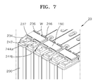
- FIG. 7 is a schematic perspective view illustrating a portion of a secondary battery module 20 including secondary batteries such as that depicted in FIG. 6 .
- the secondary battery 200 may include a case 210 accommodating an electrode assembly (not shown), a cap plate 220 sealing the case 210, and a first terminal 230 and a second terminal 240 coupled to the cap plate 220.
- the case 210 and the cap plate 220 have the same structures as the case 110 and the cap plate 120 described with reference to FIGS. 1 to 5 . Thus, descriptions thereof will not be repeated for the sake of brevity.
- the first terminal 230 includes a first terminal plate 234, and the first terminal plate 234 includes a first guide element 236 preferably formed by bending an end portion thereof.
- the first terminal plate 234 may further include a first protrusion 237.
- the first protrusion 237 protrudes outward from the top surface of the first terminal plate 234, i.e. away from the cap plate 220, and is spaced apart from the first guide element 236 and parallel with the first guide element 236.
- the first protrusion 237 and the first terminal plate 234 may be formed in one piece by using the first material.
- the first protrusion 237 and the first guide element 236 may have the same height.
- the second terminal 240 includes a first part 244a and a second part 244b that may be continuously formed.
- the first part 244a may be formed of the second material (e. g. copper), and the second part 244b may be formed of the first material (e. g. aluminum) used to form the first terminal 230.
- the second part 244b preferably includes a second guide element 246 that may be formed by bending an end portion thereof.
- the second part 244b may further include a second protrusion 247 protruding outward from the top surface of the second part 244b, i.e. away from the cap plate 220, and being spaced apart from the second guide element 246 in parallel with the second guide element 246.
- the second protrusion 247 and the second part 244b may be formed in one piece by using the first material, and the second protrusion 247 and the second guide element 246 may have the same height.
- FIG. 7 illustrates the secondary battery module 20 in which the secondary batteries 200 are connected through bus bars 180.
- a side of one of the bus bars 180 is disposed between the first protrusion 237 and the first guide element 236 of a secondary battery 200, and the other side of the bus bar 180 is disposed between the second protrusion 247 and the second guide element 246 of a neighboring secondary battery 200.
- the bus bar 180 is welded to form straight welding lines W along boundary lines among the bus bar 180, the first protrusion 237, the first guide element 236, the second protrusion 247, and the second guide element 246.
- the first protrusion 237, the first guide element 236, the second protrusion 247, and the second guide element 246 may define an assembling position of the bus bar 180 and may prevent the bus bar 180 from separating from the assembling position. Therefore, the efficiency of the welding process may be improved.
- first protrusion 237, the first guide element 236, the second protrusion 247, and the second protrusion 247 are formed of the same material as that used to form the bus bar 180, high bonding strength may be guaranteed therebetween.
- first protrusion 237, the first guide element 236, the second protrusion 247, the second protrusion 247, and the bus bar 180 have the same height and are welded along straight lines in a state that the top surfaces thereof are aligned, the welding process may be easily performed.
- the positions of the bus bars correspond to predetermined positions, and the bonding strength between the bus bars and the secondary batteries may be high.
Landscapes
- Chemical & Material Sciences (AREA)
- Chemical Kinetics & Catalysis (AREA)
- Electrochemistry (AREA)
- General Chemical & Material Sciences (AREA)
- Engineering & Computer Science (AREA)
- Manufacturing & Machinery (AREA)
- Connection Of Batteries Or Terminals (AREA)
- Battery Mounting, Suspending (AREA)
Applications Claiming Priority (1)
| Application Number | Priority Date | Filing Date | Title |
|---|---|---|---|
| KR1020130161773A KR101689217B1 (ko) | 2013-12-23 | 2013-12-23 | 일체형 단자부를 구비한 이차전지 및 이차전지모듈 |
Publications (2)
| Publication Number | Publication Date |
|---|---|
| EP2887429A1 true EP2887429A1 (de) | 2015-06-24 |
| EP2887429B1 EP2887429B1 (de) | 2016-04-06 |
Family
ID=50630705
Family Applications (1)
| Application Number | Title | Priority Date | Filing Date |
|---|---|---|---|
| EP14167283.2A Not-in-force EP2887429B1 (de) | 2013-12-23 | 2014-05-07 | Sekundärbatterie und Sekundärbatteriemodul |
Country Status (3)
| Country | Link |
|---|---|
| US (1) | US9608252B2 (de) |
| EP (1) | EP2887429B1 (de) |
| KR (1) | KR101689217B1 (de) |
Cited By (1)
| Publication number | Priority date | Publication date | Assignee | Title |
|---|---|---|---|---|
| WO2019151359A1 (ja) * | 2018-01-31 | 2019-08-08 | 株式会社Gsユアサ | 蓄電素子 |
Families Citing this family (9)
| Publication number | Priority date | Publication date | Assignee | Title |
|---|---|---|---|---|
| KR102207903B1 (ko) | 2016-07-12 | 2021-01-25 | 삼성에스디아이 주식회사 | 이차 전지 |
| KR102161627B1 (ko) * | 2016-11-29 | 2020-10-05 | 삼성에스디아이 주식회사 | 이차 전지 |
| US10658646B2 (en) * | 2017-09-12 | 2020-05-19 | Chongqing Jinkang New Energy Vehicle Co., Ltd. | Integrated current collector for electric vehicle battery cell |
| CN209045657U (zh) * | 2018-12-26 | 2019-06-28 | 宁德时代新能源科技股份有限公司 | 电池模组 |
| JP7147576B2 (ja) | 2019-01-17 | 2022-10-05 | トヨタ自動車株式会社 | 組電池、及び、組電池の製造方法 |
| KR102409422B1 (ko) * | 2019-02-22 | 2022-06-15 | 주식회사 엘지에너지솔루션 | 배터리 셀 연결용 버스 바, 배터리 팩 및 이의 제조 방법 |
| KR20230049336A (ko) | 2021-10-06 | 2023-04-13 | 에스케이온 주식회사 | 이차 전지 |
| CN118476116A (zh) * | 2022-09-08 | 2024-08-09 | 宁德时代新能源科技股份有限公司 | 隔板组件、电池单体、电池和用电装置 |
| JP7677310B2 (ja) * | 2022-11-11 | 2025-05-15 | トヨタ自動車株式会社 | 蓄電セル |
Citations (5)
| Publication number | Priority date | Publication date | Assignee | Title |
|---|---|---|---|---|
| EP2312675A1 (de) * | 2009-10-01 | 2011-04-20 | SB LiMotive Co., Ltd. | Elektrisch leitende Verbindung zwischen Elektrode und Batteriepol |
| EP2312674A1 (de) * | 2009-10-05 | 2011-04-20 | SB LiMotive Co., Ltd. | Batterieverbinder |
| EP2372814A2 (de) * | 2010-03-30 | 2011-10-05 | SB LiMotive Co., Ltd. | Sekundärbatterie und Sekundärbatteriemodul |
| US20110311863A1 (en) * | 2010-06-16 | 2011-12-22 | Sangwon Byun | Secondary battery |
| EP2410595A1 (de) * | 2010-07-21 | 2012-01-25 | SB LiMotive Co., Ltd. | Pol einer wiederaufladbaren Batterie und Herstellungsverfahren dafür |
Family Cites Families (8)
| Publication number | Priority date | Publication date | Assignee | Title |
|---|---|---|---|---|
| JP5080199B2 (ja) * | 2007-10-19 | 2012-11-21 | プライムアースEvエナジー株式会社 | 二次電池および二次電池の製造方法 |
| JP5402318B2 (ja) * | 2009-06-30 | 2014-01-29 | 株式会社Gsユアサ | 電池 |
| US9105911B2 (en) | 2009-12-28 | 2015-08-11 | Samsung Sdi Co., Ltd. | Battery module |
| KR101217073B1 (ko) * | 2010-03-30 | 2012-12-31 | 로베르트 보쉬 게엠베하 | 이차전지 및 이차전지모듈 |
| KR101135510B1 (ko) * | 2010-05-20 | 2012-04-13 | 에스비리모티브 주식회사 | 이차 전지 및 전지 모듈 |
| JP2012160339A (ja) | 2011-01-31 | 2012-08-23 | Sanyo Electric Co Ltd | 組電池および電池接続方法 |
| JP5651557B2 (ja) * | 2011-08-02 | 2015-01-14 | 日立オートモティブシステムズ株式会社 | 単電池および組電池 |
| KR20130049984A (ko) | 2011-11-07 | 2013-05-15 | 아이피지 포토닉스 코리아(주) | 배터리를 위한 버스바 및 이를 이용한 배터리 모듈 |
-
2013
- 2013-12-23 KR KR1020130161773A patent/KR101689217B1/ko active Active
-
2014
- 2014-05-07 EP EP14167283.2A patent/EP2887429B1/de not_active Not-in-force
- 2014-09-03 US US14/476,721 patent/US9608252B2/en active Active
Patent Citations (5)
| Publication number | Priority date | Publication date | Assignee | Title |
|---|---|---|---|---|
| EP2312675A1 (de) * | 2009-10-01 | 2011-04-20 | SB LiMotive Co., Ltd. | Elektrisch leitende Verbindung zwischen Elektrode und Batteriepol |
| EP2312674A1 (de) * | 2009-10-05 | 2011-04-20 | SB LiMotive Co., Ltd. | Batterieverbinder |
| EP2372814A2 (de) * | 2010-03-30 | 2011-10-05 | SB LiMotive Co., Ltd. | Sekundärbatterie und Sekundärbatteriemodul |
| US20110311863A1 (en) * | 2010-06-16 | 2011-12-22 | Sangwon Byun | Secondary battery |
| EP2410595A1 (de) * | 2010-07-21 | 2012-01-25 | SB LiMotive Co., Ltd. | Pol einer wiederaufladbaren Batterie und Herstellungsverfahren dafür |
Cited By (4)
| Publication number | Priority date | Publication date | Assignee | Title |
|---|---|---|---|---|
| WO2019151359A1 (ja) * | 2018-01-31 | 2019-08-08 | 株式会社Gsユアサ | 蓄電素子 |
| JPWO2019151359A1 (ja) * | 2018-01-31 | 2021-01-28 | 株式会社Gsユアサ | 蓄電素子 |
| JP7163932B2 (ja) | 2018-01-31 | 2022-11-01 | 株式会社Gsユアサ | 蓄電素子 |
| US12166221B2 (en) | 2018-01-31 | 2024-12-10 | Gs Yuasa International Ltd. | Energy storage device having a gap between an electrode terminal and an insulating member |
Also Published As
| Publication number | Publication date |
|---|---|
| KR20150073738A (ko) | 2015-07-01 |
| EP2887429B1 (de) | 2016-04-06 |
| KR101689217B1 (ko) | 2016-12-23 |
| US9608252B2 (en) | 2017-03-28 |
| US20150180008A1 (en) | 2015-06-25 |
Similar Documents
| Publication | Publication Date | Title |
|---|---|---|
| EP2887429B1 (de) | Sekundärbatterie und Sekundärbatteriemodul | |
| EP2602840B1 (de) | Sekundärbatteriebeutel mit verbesserter stabilität, beutel-sekundärbatterie damit und mittelgrosses oder grosses batteriepack | |
| JP5564278B2 (ja) | 二次電池 | |
| CN109690819B (zh) | 具有压纹安全通气部的二次电池 | |
| EP2985812B1 (de) | Sekundäre batterie | |
| US8535822B2 (en) | Electrode assembly and secondary battery having the same | |
| KR102288544B1 (ko) | 이차 전지 및 그 제조 방법 | |
| US10199616B2 (en) | Battery pack including cell frames coupled to each other | |
| KR102251330B1 (ko) | 이차 전지 | |
| KR20200032987A (ko) | 이차 전지 | |
| KR20150047417A (ko) | 퓨즈부를 갖는 이차 전지 및 전지 모듈 | |
| KR20080067105A (ko) | 캡 조립체 및 이를 구비한 이차 전지 | |
| US10522813B2 (en) | Secondary battery | |
| US10312497B2 (en) | Rechargeable battery | |
| KR102221808B1 (ko) | 이차 전지 | |
| KR100814853B1 (ko) | 전지 모듈 | |
| KR102041327B1 (ko) | 2차 전지 및 2차 전지 제조 방법 | |
| KR102248595B1 (ko) | 이차 전지 | |
| KR102172843B1 (ko) | 이차 전지 | |
| US9525163B2 (en) | Secondary battery and secondary battery module | |
| EP2985809B1 (de) | Batteriepack | |
| KR102078801B1 (ko) | 전극조립체 및 전극조립체 제작 방법 | |
| US10115957B2 (en) | Secondary battery | |
| KR102350769B1 (ko) | 이차 전지 | |
| KR101783920B1 (ko) | 케이블에 연결 가능한 전지 리드 및 그 제조방법 |
Legal Events
| Date | Code | Title | Description |
|---|---|---|---|
| PUAI | Public reference made under article 153(3) epc to a published international application that has entered the european phase |
Free format text: ORIGINAL CODE: 0009012 |
|
| 17P | Request for examination filed |
Effective date: 20150204 |
|
| AK | Designated contracting states |
Kind code of ref document: A1 Designated state(s): AL AT BE BG CH CY CZ DE DK EE ES FI FR GB GR HR HU IE IS IT LI LT LU LV MC MK MT NL NO PL PT RO RS SE SI SK SM TR |
|
| AX | Request for extension of the european patent |
Extension state: BA ME |
|
| GRAP | Despatch of communication of intention to grant a patent |
Free format text: ORIGINAL CODE: EPIDOSNIGR1 |
|
| RIC1 | Information provided on ipc code assigned before grant |
Ipc: H01M 4/64 20060101ALI20150924BHEP Ipc: H01M 2/20 20060101ALI20150924BHEP Ipc: H01M 2/26 20060101ALI20150924BHEP Ipc: H01M 2/30 20060101AFI20150924BHEP |
|
| INTG | Intention to grant announced |
Effective date: 20151014 |
|
| GRAS | Grant fee paid |
Free format text: ORIGINAL CODE: EPIDOSNIGR3 |
|
| GRAA | (expected) grant |
Free format text: ORIGINAL CODE: 0009210 |
|
| AK | Designated contracting states |
Kind code of ref document: B1 Designated state(s): AL AT BE BG CH CY CZ DE DK EE ES FI FR GB GR HR HU IE IS IT LI LT LU LV MC MK MT NL NO PL PT RO RS SE SI SK SM TR |
|
| REG | Reference to a national code |
Ref country code: GB Ref legal event code: FG4D |
|
| REG | Reference to a national code |
Ref country code: AT Ref legal event code: REF Ref document number: 788643 Country of ref document: AT Kind code of ref document: T Effective date: 20160415 Ref country code: CH Ref legal event code: EP |
|
| REG | Reference to a national code |
Ref country code: IE Ref legal event code: FG4D |
|
| REG | Reference to a national code |
Ref country code: DE Ref legal event code: R096 Ref document number: 602014001346 Country of ref document: DE |
|
| REG | Reference to a national code |
Ref country code: FR Ref legal event code: PLFP Year of fee payment: 3 |
|
| REG | Reference to a national code |
Ref country code: LT Ref legal event code: MG4D Ref country code: NL Ref legal event code: MP Effective date: 20160406 |
|
| REG | Reference to a national code |
Ref country code: AT Ref legal event code: MK05 Ref document number: 788643 Country of ref document: AT Kind code of ref document: T Effective date: 20160406 |
|
| PG25 | Lapsed in a contracting state [announced via postgrant information from national office to epo] |
Ref country code: BE Free format text: LAPSE BECAUSE OF NON-PAYMENT OF DUE FEES Effective date: 20160531 |
|
| PG25 | Lapsed in a contracting state [announced via postgrant information from national office to epo] |
Ref country code: NL Free format text: LAPSE BECAUSE OF FAILURE TO SUBMIT A TRANSLATION OF THE DESCRIPTION OR TO PAY THE FEE WITHIN THE PRESCRIBED TIME-LIMIT Effective date: 20160406 |
|
| PG25 | Lapsed in a contracting state [announced via postgrant information from national office to epo] |
Ref country code: PL Free format text: LAPSE BECAUSE OF FAILURE TO SUBMIT A TRANSLATION OF THE DESCRIPTION OR TO PAY THE FEE WITHIN THE PRESCRIBED TIME-LIMIT Effective date: 20160406 Ref country code: LT Free format text: LAPSE BECAUSE OF FAILURE TO SUBMIT A TRANSLATION OF THE DESCRIPTION OR TO PAY THE FEE WITHIN THE PRESCRIBED TIME-LIMIT Effective date: 20160406 Ref country code: NO Free format text: LAPSE BECAUSE OF FAILURE TO SUBMIT A TRANSLATION OF THE DESCRIPTION OR TO PAY THE FEE WITHIN THE PRESCRIBED TIME-LIMIT Effective date: 20160706 Ref country code: FI Free format text: LAPSE BECAUSE OF FAILURE TO SUBMIT A TRANSLATION OF THE DESCRIPTION OR TO PAY THE FEE WITHIN THE PRESCRIBED TIME-LIMIT Effective date: 20160406 Ref country code: IS Free format text: LAPSE BECAUSE OF FAILURE TO SUBMIT A TRANSLATION OF THE DESCRIPTION OR TO PAY THE FEE WITHIN THE PRESCRIBED TIME-LIMIT Effective date: 20160806 |
|
| PG25 | Lapsed in a contracting state [announced via postgrant information from national office to epo] |
Ref country code: GR Free format text: LAPSE BECAUSE OF FAILURE TO SUBMIT A TRANSLATION OF THE DESCRIPTION OR TO PAY THE FEE WITHIN THE PRESCRIBED TIME-LIMIT Effective date: 20160707 Ref country code: HR Free format text: LAPSE BECAUSE OF FAILURE TO SUBMIT A TRANSLATION OF THE DESCRIPTION OR TO PAY THE FEE WITHIN THE PRESCRIBED TIME-LIMIT Effective date: 20160406 Ref country code: LV Free format text: LAPSE BECAUSE OF FAILURE TO SUBMIT A TRANSLATION OF THE DESCRIPTION OR TO PAY THE FEE WITHIN THE PRESCRIBED TIME-LIMIT Effective date: 20160406 Ref country code: RS Free format text: LAPSE BECAUSE OF FAILURE TO SUBMIT A TRANSLATION OF THE DESCRIPTION OR TO PAY THE FEE WITHIN THE PRESCRIBED TIME-LIMIT Effective date: 20160406 Ref country code: SE Free format text: LAPSE BECAUSE OF FAILURE TO SUBMIT A TRANSLATION OF THE DESCRIPTION OR TO PAY THE FEE WITHIN THE PRESCRIBED TIME-LIMIT Effective date: 20160406 Ref country code: ES Free format text: LAPSE BECAUSE OF FAILURE TO SUBMIT A TRANSLATION OF THE DESCRIPTION OR TO PAY THE FEE WITHIN THE PRESCRIBED TIME-LIMIT Effective date: 20160406 Ref country code: AT Free format text: LAPSE BECAUSE OF FAILURE TO SUBMIT A TRANSLATION OF THE DESCRIPTION OR TO PAY THE FEE WITHIN THE PRESCRIBED TIME-LIMIT Effective date: 20160406 Ref country code: PT Free format text: LAPSE BECAUSE OF FAILURE TO SUBMIT A TRANSLATION OF THE DESCRIPTION OR TO PAY THE FEE WITHIN THE PRESCRIBED TIME-LIMIT Effective date: 20160808 |
|
| PG25 | Lapsed in a contracting state [announced via postgrant information from national office to epo] |
Ref country code: IT Free format text: LAPSE BECAUSE OF FAILURE TO SUBMIT A TRANSLATION OF THE DESCRIPTION OR TO PAY THE FEE WITHIN THE PRESCRIBED TIME-LIMIT Effective date: 20160406 Ref country code: BE Free format text: LAPSE BECAUSE OF FAILURE TO SUBMIT A TRANSLATION OF THE DESCRIPTION OR TO PAY THE FEE WITHIN THE PRESCRIBED TIME-LIMIT Effective date: 20160406 |
|
| REG | Reference to a national code |
Ref country code: DE Ref legal event code: R097 Ref document number: 602014001346 Country of ref document: DE |
|
| PG25 | Lapsed in a contracting state [announced via postgrant information from national office to epo] |
Ref country code: SK Free format text: LAPSE BECAUSE OF FAILURE TO SUBMIT A TRANSLATION OF THE DESCRIPTION OR TO PAY THE FEE WITHIN THE PRESCRIBED TIME-LIMIT Effective date: 20160406 Ref country code: MC Free format text: LAPSE BECAUSE OF FAILURE TO SUBMIT A TRANSLATION OF THE DESCRIPTION OR TO PAY THE FEE WITHIN THE PRESCRIBED TIME-LIMIT Effective date: 20160406 Ref country code: DK Free format text: LAPSE BECAUSE OF FAILURE TO SUBMIT A TRANSLATION OF THE DESCRIPTION OR TO PAY THE FEE WITHIN THE PRESCRIBED TIME-LIMIT Effective date: 20160406 Ref country code: CZ Free format text: LAPSE BECAUSE OF FAILURE TO SUBMIT A TRANSLATION OF THE DESCRIPTION OR TO PAY THE FEE WITHIN THE PRESCRIBED TIME-LIMIT Effective date: 20160406 Ref country code: EE Free format text: LAPSE BECAUSE OF FAILURE TO SUBMIT A TRANSLATION OF THE DESCRIPTION OR TO PAY THE FEE WITHIN THE PRESCRIBED TIME-LIMIT Effective date: 20160406 Ref country code: RO Free format text: LAPSE BECAUSE OF FAILURE TO SUBMIT A TRANSLATION OF THE DESCRIPTION OR TO PAY THE FEE WITHIN THE PRESCRIBED TIME-LIMIT Effective date: 20160406 |
|
| PLBE | No opposition filed within time limit |
Free format text: ORIGINAL CODE: 0009261 |
|
| STAA | Information on the status of an ep patent application or granted ep patent |
Free format text: STATUS: NO OPPOSITION FILED WITHIN TIME LIMIT |
|
| REG | Reference to a national code |
Ref country code: IE Ref legal event code: MM4A |
|
| PG25 | Lapsed in a contracting state [announced via postgrant information from national office to epo] |
Ref country code: SM Free format text: LAPSE BECAUSE OF FAILURE TO SUBMIT A TRANSLATION OF THE DESCRIPTION OR TO PAY THE FEE WITHIN THE PRESCRIBED TIME-LIMIT Effective date: 20160406 |
|
| 26N | No opposition filed |
Effective date: 20170110 |
|
| REG | Reference to a national code |
Ref country code: FR Ref legal event code: PLFP Year of fee payment: 4 |
|
| PG25 | Lapsed in a contracting state [announced via postgrant information from national office to epo] |
Ref country code: SI Free format text: LAPSE BECAUSE OF FAILURE TO SUBMIT A TRANSLATION OF THE DESCRIPTION OR TO PAY THE FEE WITHIN THE PRESCRIBED TIME-LIMIT Effective date: 20160406 Ref country code: IE Free format text: LAPSE BECAUSE OF NON-PAYMENT OF DUE FEES Effective date: 20160507 |
|
| REG | Reference to a national code |
Ref country code: CH Ref legal event code: PL |
|
| PG25 | Lapsed in a contracting state [announced via postgrant information from national office to epo] |
Ref country code: CH Free format text: LAPSE BECAUSE OF NON-PAYMENT OF DUE FEES Effective date: 20170531 Ref country code: LI Free format text: LAPSE BECAUSE OF NON-PAYMENT OF DUE FEES Effective date: 20170531 |
|
| REG | Reference to a national code |
Ref country code: FR Ref legal event code: PLFP Year of fee payment: 5 |
|
| PG25 | Lapsed in a contracting state [announced via postgrant information from national office to epo] |
Ref country code: HU Free format text: LAPSE BECAUSE OF FAILURE TO SUBMIT A TRANSLATION OF THE DESCRIPTION OR TO PAY THE FEE WITHIN THE PRESCRIBED TIME-LIMIT; INVALID AB INITIO Effective date: 20140507 |
|
| PG25 | Lapsed in a contracting state [announced via postgrant information from national office to epo] |
Ref country code: MK Free format text: LAPSE BECAUSE OF FAILURE TO SUBMIT A TRANSLATION OF THE DESCRIPTION OR TO PAY THE FEE WITHIN THE PRESCRIBED TIME-LIMIT Effective date: 20160406 Ref country code: MT Free format text: LAPSE BECAUSE OF NON-PAYMENT OF DUE FEES Effective date: 20160531 Ref country code: CY Free format text: LAPSE BECAUSE OF FAILURE TO SUBMIT A TRANSLATION OF THE DESCRIPTION OR TO PAY THE FEE WITHIN THE PRESCRIBED TIME-LIMIT Effective date: 20160406 Ref country code: LU Free format text: LAPSE BECAUSE OF NON-PAYMENT OF DUE FEES Effective date: 20160507 |
|
| PG25 | Lapsed in a contracting state [announced via postgrant information from national office to epo] |
Ref country code: BG Free format text: LAPSE BECAUSE OF FAILURE TO SUBMIT A TRANSLATION OF THE DESCRIPTION OR TO PAY THE FEE WITHIN THE PRESCRIBED TIME-LIMIT Effective date: 20160406 |
|
| PG25 | Lapsed in a contracting state [announced via postgrant information from national office to epo] |
Ref country code: TR Free format text: LAPSE BECAUSE OF FAILURE TO SUBMIT A TRANSLATION OF THE DESCRIPTION OR TO PAY THE FEE WITHIN THE PRESCRIBED TIME-LIMIT Effective date: 20160406 Ref country code: AL Free format text: LAPSE BECAUSE OF FAILURE TO SUBMIT A TRANSLATION OF THE DESCRIPTION OR TO PAY THE FEE WITHIN THE PRESCRIBED TIME-LIMIT Effective date: 20160406 |
|
| REG | Reference to a national code |
Ref country code: DE Ref legal event code: R079 Ref document number: 602014001346 Country of ref document: DE Free format text: PREVIOUS MAIN CLASS: H01M0002300000 Ipc: H01M0050543000 |
|
| P01 | Opt-out of the competence of the unified patent court (upc) registered |
Effective date: 20230528 |
|
| PGFP | Annual fee paid to national office [announced via postgrant information from national office to epo] |
Ref country code: GB Payment date: 20240425 Year of fee payment: 11 |
|
| PGFP | Annual fee paid to national office [announced via postgrant information from national office to epo] |
Ref country code: DE Payment date: 20240502 Year of fee payment: 11 |
|
| PGFP | Annual fee paid to national office [announced via postgrant information from national office to epo] |
Ref country code: FR Payment date: 20240509 Year of fee payment: 11 |
|
| REG | Reference to a national code |
Ref country code: DE Ref legal event code: R119 Ref document number: 602014001346 Country of ref document: DE |
|
| GBPC | Gb: european patent ceased through non-payment of renewal fee |
Effective date: 20250507 |
|
| PG25 | Lapsed in a contracting state [announced via postgrant information from national office to epo] |
Ref country code: GB Free format text: LAPSE BECAUSE OF NON-PAYMENT OF DUE FEES Effective date: 20250507 |
|
| PG25 | Lapsed in a contracting state [announced via postgrant information from national office to epo] |
Ref country code: DE Free format text: LAPSE BECAUSE OF NON-PAYMENT OF DUE FEES Effective date: 20251202 |
|
| PG25 | Lapsed in a contracting state [announced via postgrant information from national office to epo] |
Ref country code: FR Free format text: LAPSE BECAUSE OF NON-PAYMENT OF DUE FEES Effective date: 20250531 |