EP2887115B1 - Leuchte - Google Patents
Leuchte Download PDFInfo
- Publication number
- EP2887115B1 EP2887115B1 EP14004190.6A EP14004190A EP2887115B1 EP 2887115 B1 EP2887115 B1 EP 2887115B1 EP 14004190 A EP14004190 A EP 14004190A EP 2887115 B1 EP2887115 B1 EP 2887115B1
- Authority
- EP
- European Patent Office
- Prior art keywords
- light
- optics
- along
- plane
- tertiary
- Prior art date
- Legal status (The legal status is an assumption and is not a legal conclusion. Google has not performed a legal analysis and makes no representation as to the accuracy of the status listed.)
- Active
Links
Images


Classifications
-
- F—MECHANICAL ENGINEERING; LIGHTING; HEATING; WEAPONS; BLASTING
- F21—LIGHTING
- F21S—NON-PORTABLE LIGHTING DEVICES; SYSTEMS THEREOF; VEHICLE LIGHTING DEVICES SPECIALLY ADAPTED FOR VEHICLE EXTERIORS
- F21S8/00—Lighting devices intended for fixed installation
-
- G—PHYSICS
- G02—OPTICS
- G02B—OPTICAL ELEMENTS, SYSTEMS OR APPARATUS
- G02B19/00—Condensers, e.g. light collectors or similar non-imaging optics
- G02B19/0033—Condensers, e.g. light collectors or similar non-imaging optics characterised by the use
- G02B19/0047—Condensers, e.g. light collectors or similar non-imaging optics characterised by the use for use with a light source
- G02B19/0061—Condensers, e.g. light collectors or similar non-imaging optics characterised by the use for use with a light source the light source comprising a LED
- G02B19/0066—Condensers, e.g. light collectors or similar non-imaging optics characterised by the use for use with a light source the light source comprising a LED in the form of an LED array
-
- F—MECHANICAL ENGINEERING; LIGHTING; HEATING; WEAPONS; BLASTING
- F21—LIGHTING
- F21V—FUNCTIONAL FEATURES OR DETAILS OF LIGHTING DEVICES OR SYSTEMS THEREOF; STRUCTURAL COMBINATIONS OF LIGHTING DEVICES WITH OTHER ARTICLES, NOT OTHERWISE PROVIDED FOR
- F21V13/00—Producing particular characteristics or distribution of the light emitted by means of a combination of elements specified in two or more of main groups F21V1/00 - F21V11/00
-
- F—MECHANICAL ENGINEERING; LIGHTING; HEATING; WEAPONS; BLASTING
- F21—LIGHTING
- F21V—FUNCTIONAL FEATURES OR DETAILS OF LIGHTING DEVICES OR SYSTEMS THEREOF; STRUCTURAL COMBINATIONS OF LIGHTING DEVICES WITH OTHER ARTICLES, NOT OTHERWISE PROVIDED FOR
- F21V5/00—Refractors for light sources
-
- F—MECHANICAL ENGINEERING; LIGHTING; HEATING; WEAPONS; BLASTING
- F21—LIGHTING
- F21V—FUNCTIONAL FEATURES OR DETAILS OF LIGHTING DEVICES OR SYSTEMS THEREOF; STRUCTURAL COMBINATIONS OF LIGHTING DEVICES WITH OTHER ARTICLES, NOT OTHERWISE PROVIDED FOR
- F21V5/00—Refractors for light sources
- F21V5/02—Refractors for light sources of prismatic shape
-
- F—MECHANICAL ENGINEERING; LIGHTING; HEATING; WEAPONS; BLASTING
- F21—LIGHTING
- F21V—FUNCTIONAL FEATURES OR DETAILS OF LIGHTING DEVICES OR SYSTEMS THEREOF; STRUCTURAL COMBINATIONS OF LIGHTING DEVICES WITH OTHER ARTICLES, NOT OTHERWISE PROVIDED FOR
- F21V5/00—Refractors for light sources
- F21V5/04—Refractors for light sources of lens shape
- F21V5/041—Ball lenses
-
- G—PHYSICS
- G02—OPTICS
- G02B—OPTICAL ELEMENTS, SYSTEMS OR APPARATUS
- G02B19/00—Condensers, e.g. light collectors or similar non-imaging optics
- G02B19/0004—Condensers, e.g. light collectors or similar non-imaging optics characterised by the optical means employed
- G02B19/0028—Condensers, e.g. light collectors or similar non-imaging optics characterised by the optical means employed refractive and reflective surfaces, e.g. non-imaging catadioptric systems
-
- G—PHYSICS
- G02—OPTICS
- G02B—OPTICAL ELEMENTS, SYSTEMS OR APPARATUS
- G02B3/00—Simple or compound lenses
- G02B3/0006—Arrays
- G02B3/0037—Arrays characterized by the distribution or form of lenses
- G02B3/0043—Inhomogeneous or irregular arrays, e.g. varying shape, size, height
-
- G—PHYSICS
- G02—OPTICS
- G02B—OPTICAL ELEMENTS, SYSTEMS OR APPARATUS
- G02B3/00—Simple or compound lenses
- G02B3/0006—Arrays
- G02B3/0037—Arrays characterized by the distribution or form of lenses
- G02B3/005—Arrays characterized by the distribution or form of lenses arranged along a single direction only, e.g. lenticular sheets
-
- G—PHYSICS
- G02—OPTICS
- G02B—OPTICAL ELEMENTS, SYSTEMS OR APPARATUS
- G02B3/00—Simple or compound lenses
- G02B3/0006—Arrays
- G02B3/0037—Arrays characterized by the distribution or form of lenses
- G02B3/0062—Stacked lens arrays, i.e. refractive surfaces arranged in at least two planes, without structurally separate optical elements in-between
- G02B3/0068—Stacked lens arrays, i.e. refractive surfaces arranged in at least two planes, without structurally separate optical elements in-between arranged in a single integral body or plate, e.g. laminates or hybrid structures with other optical elements
-
- G—PHYSICS
- G02—OPTICS
- G02B—OPTICAL ELEMENTS, SYSTEMS OR APPARATUS
- G02B5/00—Optical elements other than lenses
- G02B5/04—Prisms
- G02B5/045—Prism arrays
Definitions
- the invention relates to a combination of a building surface with a luminaire according to claim 1.
- the applicant has been developing and selling various types of luminaires for many decades.
- a luminaire that can be positioned immediately adjacent to a building surface to be illuminated and that is capable of homogeneously illuminating even very large building surfaces, in particular very high walls.
- WO 2010/010494 A1 a street lamp which serves to illuminate a floor area. It cannot be inferred from the publication that the lamp could be used on the ceiling or floor to illuminate a high, vertical wall of a building.
- the lamp described there is not designed to be elongated along a longitudinal direction, and it does not have several collimator optics arranged in a row along the longitudinal direction.
- the lamp in this publication also does not show any light deflection means provided by prisms extending in the longitudinal direction, nor any widening means formed by lenticular lenses extending along a direction transverse to the longitudinal direction of the lamp.
- the document does not show a luminaire in which light from a collimator optic is fed to a tertiary optic along a main axis with a very narrow light distribution along a first plane containing the longitudinal direction and along a second plane whose normal vector is provided by the longitudinal direction, wherein the tertiary optic has widening means by means of which a widening of the light distribution along the first plane, and light deflection means by means of which, while maintaining a narrow or essentially narrow light distribution along the second plane, predominant portions of the total luminous flux are directed into a half-space delimited by the first plane.
- a luminaire for illuminating a building surface comprising a plurality of LEDs arranged on a substrate with a collimator optic, and comprising a tertiary optic in the form of a translucent, in particular planar element, characterized in that the tertiary optic has several areas with different transmission properties, and that the tertiary optic is arranged displaceably relative to the substrate, wherein a first light distribution can be generated with the tertiary optic located in a first position and a second light distribution can be generated with the tertiary optic located in a second position.
- the invention is based on the object of providing a luminaire which can be arranged immediately adjacent to a building surface to be illuminated and which is capable of homogeneously illuminating even very large building surfaces, in particular very high walls.
- the invention solves the problem with the features of claim 1.
- the invention relates to a lamp for illuminating a building surface.
- a building surface Any interior or exterior surface of a building, in particular a vertical wall surface, is referred to as a building surface.
- parts of a building or objects to be illuminated, statues, items of equipment or the like are also referred to as building surfaces.
- the luminaire is preferably mounted on the ceiling or floor, immediately adjacent to a very high vertical wall of a building room that is to be illuminated.
- the arrangement of the luminaire according to the invention in or on a ceiling or floor niche, a so-called cove, is particularly advantageous for the purpose of illuminating very high vertical wall surfaces, for example up to 10 meters high.
- the lamp according to the invention is designed to be elongated in the longitudinal direction. It is therefore longer than it is wide or high. It is therefore a linear lamp. It can be combined in particular along a straight line with a large number of similarly designed lamps to form a row arrangement.
- the luminaire generates a first light distribution along a first plane and a second light distribution along a second plane.
- the first and second light distributions are designed differently.
- the first plane contains the longitudinal direction of the light. This is a plane that is, for example, parallel to the plane of the building surface to be illuminated. The latter of course assumes that the building surface is also flat.
- the second plane is perpendicular to the first plane.
- the second plane is a plane whose normal vector is the longitudinal direction of the lamp. The normal vector is therefore perpendicular to the plane.
- the second plane represents - in other words - the plane of a cross-section through the lamp.
- the luminaire comprises a plurality of LEDs as primary optics.
- the plurality of LEDs are preferably arranged along the longitudinal direction, further preferably spaced apart from one another, further preferably spaced apart from one another along a regular grid.
- Each LED is assigned a collimator optic as a secondary optic. It can be provided that either each individual LED is assigned its own collimator optic, or a group of several LEDs, for example a group of several light-emitting LEDs of different colors, is assigned a collimator optic as a secondary optic.
- the luminaire also comprises a plurality of collimator optics which are arranged at a distance from one another or abutting one another along the longitudinal direction.
- the luminaire in any case comprises a series of collimator optics along the longitudinal direction of the luminaire.
- the collimator optics bundle the light emitted by the LED or LEDs. It guides the light to the tertiary optics along a main axis.
- the light is fed from the collimator optics to the tertiary optics both along the first plane with a very narrow light distribution and along the second plane with a very narrow light distribution.
- a rotationally symmetrical, narrow light distribution is particularly advantageous.
- a very narrow light distribution within the meaning of the present patent application is understood to mean a light distribution that comprises light directed almost parallel, or light with an opening angle of less than 10°.
- the tertiary optics are advantageously arranged at a distance from the light exit surface of the secondary optics.
- the tertiary optics also preferably have a light entry surface and a light exit surface.
- the tertiary optics can, for example, be formed by a substantially plate-shaped, flat element.
- the tertiary optics has widening means.
- the widening means ensure that the light distribution is widened along a first plane E1.
- the light emission angle is therefore increased along the first plane E1 by the widening means.
- Such a light broadening can be achieved, for example, by arranging lens elements, namely so-called diverging lenses or scattering lenses, and in particular preferably by arranging lenticular lenses.
- the tertiary optics further comprises light deflection means.
- a deflection of the predominant portions of the total luminous flux of the lamp can be carried out into a half-space.
- the half-space into which the predominant portions of the total luminous flux are directed is limited by the first plane E1.
- more than 55% of the portions of the total luminous flux further advantageously more than 60%, further advantageously more than 70%, further advantageously more than 75%, and further advantageously about 80% or more than 80% of the total luminous flux emitted by the luminaire is directed into this one half-space.
- the light deflection means can direct the portions of the luminous flux into the half-space delimited by the first plane while maintaining the narrow, or essentially narrow, light distribution along the second plane.
- the narrow light distribution along the second plane is limited to angles of less than 40°, preferably less than 30°, preferably less than 20°.
- the beam angle of the narrow light distribution along the second plane E2 is approximately between 4° and 10°.
- the luminaire designed according to the invention can be arranged, for example, on the ceiling side in a recess provided for this purpose, a cove, in any case immediately adjacent to the wall to be illuminated.
- the wall can extend along any length, whereby the length of the luminaire can also be selected according to the length of the wall, or a large number of luminaires can be arranged in a row one behind the other in the longitudinal direction, and the length of the row arrangement of luminaires thus formed can correspond to the length of the wall.
- the wall can have a height of up to 10 m, for example.
- the entire wall surface can be evenly and homogeneously illuminated with the described geometric arrangement of the luminaire relative to the wall.
- collimator optics are arranged directly adjacent to one another, providing a row arrangement, along the longitudinal direction.
- the direct proximity of collimator optics can, for example, include the collimator optics being combined so as to be close to one another, abutting against one another, to form a row arrangement.
- An inventive combination of a building surface with a luminaire according to claim 1 also allows a spacing of collimator optics from one another in the longitudinal direction.
- the light deflection means serve to equalize the light in the sense of homogenizing the light distribution along a light emission angle along the second plane.
- the light deflection means are arranged in the form of prisms directly on the tertiary optics, for example on the light exit surface of the tertiary optics.
- the arrangement of the individual prism surfaces i.e. their positioning and their design, can advantageously be calculated so that a very uniform deflection of the luminous flux occurs along the light emission angle along the second plane E2. This enables a homogeneous illumination of the entire building surface to be illuminated, from a section of the building surface positioned very close to the luminaire to a section of the building surface that is as far away from the luminaire as possible.
- the prisms can be designed and positioned differently with regard to their angle of attack, their height and their axial length and width.
- the light from the secondary optics hits the tertiary optics essentially as a parallel bundle of light rays.
- the secondary optics are advantageously designed to have such a narrow beam that a parallel or almost parallel bundle of light rays is generated.
- a light entry surface of the tertiary optics is arranged at a distance from a light exit surface of the secondary optics.
- the spacing can be between 1 mm and 50 mm.
- the distance is approximately between 3 mm and 20 mm.
- the secondary optics emits a light beam which is arranged around its central axis substantially rotationally symmetrical light distribution.
- this makes it possible to use conventional, well-known collimator optics.
- this provides a construction that enables very targeted further processing of the luminous flux and the arrangement of the lighting elements intended for this purpose within the luminaire.
- the widening means are arranged on one side of the tertiary optics and the light deflection means on the other side of the tertiary optics.
- the widening means are arranged on the light entry surface of the tertiary optics and the light deflection means on the exit side of the tertiary optics.
- the tertiary optics are formed by a planar, in particular flat, and more particularly by a plate-shaped element.
- the light spreading means and the light deflecting means are designed as microstructures of a light entry surface or alternatively a light exit surface of the same element.
- the spreading means and the light deflecting means are superimposed on one another, so to speak. Free-form surfaces, for example of a drop-shaped type, can be simulated and constructed using appropriate simulations. In terms of lighting technology, the same effect can be achieved as when spreading means are attached to the light entry surface of the tertiary optics and Light-guiding means are arranged on the light exit surface of the tertiary optics.
- the tertiary optics are formed by two or more elements, in particular by two or more planar, in particular flat, and further in particular plate-shaped elements.
- the widening means and the light deflection means can be formed as microstructures on the different elements. This enables a further simplified design and manufacture of the tertiary optics.
- such an embodiment of the invention is not as efficient as the preferred embodiment of the invention, in which light widening means are arranged on one side of the tertiary optics and light deflection means are arranged on the other side of the same tertiary optics.
- the widening means are formed by lenticular lenses. These each extend along a direction transverse to the longitudinal direction of the lamp.
- Lenticular lenses are understood to be particularly elongated, lens-shaped elements as part of the surface of the tertiary optics, which are provided by a partial surface of a circular cylinder.
- a parallel bundle of light rays relating to a tertiary optic with widening means designed as lenticular lenses is spread by a predetermined amount, i.e. to a specific light emission angle.
- the light is broadened along the plane E1 to a light emission angle of less than 100°, more particularly less than 90° and more particularly less than 80°.
- the light is broadened along the plane E1 to a light emission angle of more than 20°, in particular more than 30°, in particular more than 50°.
- the light deflection means are formed by a plurality of prisms.
- the prisms vary in particular in their angle of attack, in their width, in their axial length and in their height.
- the angle of radiation or the angle specification of a light distribution in the sense of the present invention refers in particular to the angle which is referred to in the expert sense as the opening angle and represents the "full width half max" value. This is therefore the value of the light radiation angle at which the light intensity has fallen to approximately half the maximum light intensity.
- Fig. 1 first illustrates the position of a lamp according to the invention, designated in its entirety by 10. This is intended for illuminating a building surface 12 of a building room 11.
- the building space 11 has a suspended ceiling 13, which is fixed by means of mounting elements 14a, 14b that are only indicated schematically.
- the suspended ceiling 13 is also referred to as a false ceiling, plasterboard ceiling, ceiling construction or the like.
- the building surface 12 to be illuminated is a vertical building wall. This can have a very large height WH of, for example, up to 10 meters.
- the luminaire 10 according to the invention is arranged in this cove.
- the distance AB2 between the luminaire 10 and the building surface 12 can be only a few centimeters, for example only 10 cm.
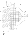
- FIG. 2 an embodiment of the lamp according to the invention is shown in a bottom view. It can be seen that the lamp 10 has a width B and a length L. The lamp is therefore elongated in the longitudinal direction R.
- the embodiment of the luminaire 10 according to Fig. 2 has a light exit opening 28 which is essentially rectangular and has approximately the dimensions width B x length L.
- luminaires 10 can be arranged next to one another in the longitudinal direction R, in particular also abutting one another, in order to form a luminaire construction with a total length which corresponds to the total length or a large part of the total length of the building area 12 to be illuminated.
- the cove 15 also preferably extends along the entire length or along a large part of the length of the wall 12.
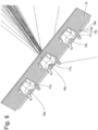
- the first type of luminaire according to the invention according to the Figures 2 to 8 has a plurality of LEDs 18 (e.g. 18a, 18b, 18c), which are referred to as primary optics, a plurality of collimator optics 17, which are referred to as secondary optics, and a tertiary optic 16 in the form of a plate-shaped element.
- LEDs 18 e.g. 18a, 18b, 18c
- secondary optics e.g. 18a, 18b, 18c
- tertiary optic 16 in the form of a plate-shaped element.
- a first collimator optics 17a, a second collimator optics 17b, and a third collimator optics 17c are shown.
- an LED 18a, an LED 18b and an LED 18c are shown in the center of the collimator optics 17 in the center of the collimator optics 17.
- the LED 18a can be a single LED or a group of LEDs.
- the collimator optics 17 are essentially rotationally symmetrical and, as best seen from the Figures 3 and 4 As can be seen, it has a cavity 29 which provides a receptacle for the LEDs.
- the light emitted by the LEDs 18 is strongly bundled with the aid of total reflection surfaces and leaves the collimator optics 17 through the light exit surface 25 of the collimator optics 17.
- a light entry surface 23 of the tertiary optics 16 is located at a distance Z from the light exit surface 25 of the collimator optics 17.
- the tertiary optics 16 is designed as a substantially plate-shaped, rectangular element. It is arranged in the light exit opening 28 of the lamp 10.
- the tertiary optics 16, or its light exit surface 24, provides the light exit opening 28 of the lamp 10.
- the LEDs 18a, 18b, 18c are each arranged at a distance A from each other.
- the distance A provides a grid dimension.
- the external dimensions of the collimator optics 17a, 17b, 17c are in Fig. 2 shown in dashed lines. It can be seen that two collimator optics (e.g. 17a and 17b) are spaced apart from each other. There is a free space 30 between each two collimator optics.
- the luminaire produces 10 different light distributions along the two mutually perpendicular planes E1 and E2.
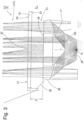
- Level E1 is defined as the Fig. 2 designated plane E1, which contains the longitudinal direction R of the luminaire 10, and in particular the longitudinal central axis MA of the luminaire 10. It is a plane E1 which is arranged essentially parallel to the building surface 12 to be illuminated. The plane E1 corresponds to the paper plane of the Fig. 4 .
- the plane E2 perpendicular to this, or second plane E2 is the plane E2 which corresponds to the paper plane of the Fig. 3
- the normal vector of this plane E2 is provided by the longitudinal direction R, or by the longitudinal central axis MA.
- the widening means 19 are to be assessed based on the Fig. 4 explained:
- a plurality of lenticular lenses 20 are arranged on the light entry surface 23 of the tertiary optics 16. These extend along the entire width B of the tertiary optics 16 transversely to the paper plane of the Fig. 4
- the parallel or essentially parallel light beam 31 emitted by the collimator optics 17, which is shown by the Fig. 4 a very narrow light distribution along the plane E1 hits the widening means 19, 20, 20a, 20b, 20c and is thereby widened. This results in light emission along the plane E1 at an angle ⁇ of approximately 80°.
- the parallel light beam 31, which hits the light entry surface 23 of the tertiary optics 16 along the plane E2 is not influenced by the light entry surface 23.
- an influence only takes place on the outside, or boundary surface, of the tertiary optics 16.
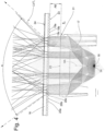
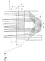
- a large number of prisms 22 are provided, which are arranged in Fig. 8 are shown slightly enlarged.
- the schematically illustrated light beam 32 which originates from the collimator optics 17 and passes the light entry surface 23 of the tertiary optics 16 without refraction, is deflected by an angle ⁇ when it hits the prism 22a. This results in a light beam 33.
- plane E1 is understood in particular to be the plane which runs as a longitudinal median plane through the luminaire 10 and which contains the longitudinal direction R or the longitudinal median axis MA.
- the plane E1 defines two half-spaces, namely a first half-space H1 and a second half-space H2.
- the first half-space H1 is the Fig. 7 only schematically indicated building area 12.
- the half-space H2 faces away from this building area 12.
- prisms 22 By arranging prisms 22 taking into account individual angles of attack ⁇ and different heights PH of a prism 22b (cf. Fig. 8 ), as well as due to its axial extension (ie the extension transverse to the plane of the paper of the Fig. 8 ) and the positioning on the light exit surface 24 of the tertiary optics 16, a corresponding light deflection and homogenization can take place.
- a light distribution can be achieved on the building surface 12 which homogeneously illuminates the building surface 12 along the entire building surface height WH and along the entire length of the building surface 12.
- a very narrow light distribution can be achieved at a beam angle ⁇ of less than 10°, which is directed exclusively into a half-space H1.
- a very broad or at least significantly broader light distribution can be achieved along the plane E1, whereby the transitions between individual, spaced-apart collimator optics or spaced-apart LEDs or groups of LEDs are homogenized.
- the lamp housing can be kept very compact and, for example, as in Fig. 1 As indicated, it should be essentially box-shaped.
- the LEDs are mounted on a Fig. 4 only schematically indicated circuit board 34, which is fixedly arranged relative to a bottom of the housing 35.
- the housing of the lamp 10 is in Fig. 1 marked 35.
- the majority of the luminous flux emitted by the luminaire 10 can be directed into the half-space H1 and thus efficiently used to illuminate the wall surface 12.
- the invention also covers luminaire types in which only a small proportion of the luminous flux is directed into the half-space H1.
- the predominant portion of the total luminous flux i.e. in particular more than 55%, preferably more than 60%, further preferably more than 70% of the total luminous flux, is to be guided or directed into the half-space H1 in order to be able to be used there to illuminate the building surface 12.
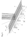
- collimator optics 17a, 17b, 17c can be overlapped by a plate-shaped tertiary optic 16. This enables a particularly advantageous optical design of the luminaire.
- the tertiary optics 16 can be designed to be continuous in this way, which enables a correspondingly uniform overall impression of the luminaire.
- the individual prisms 22a, 22b, 22c, etc. extend over the entire axial length of the tertiary optics 16. In other embodiments, the axial length of the individual prisms 22 can also be shorter.
- the scattered light beam designated 38 is intended to make it clear that sections of the building surface 12 arranged immediately adjacent to the luminaire 10 can also be illuminated with scattered light.
- edge beams are preferably used which leave the collimator optics 17 in the area 39 of its outer edge.
- a translucent window element 40 as shown in Figure 5 visible, arranged.
- the tertiary optics 16 are provided by a first plate 26 and a second plate 27. These can also be spaced apart from each other by a distance U.
- the first plate 26 provides widening means 19 on its light entry side
- the second plate 27 provides light deflection means 21 on its exit side.
- These can be designed identically to the widening means and light deflection means of the first embodiment.
- the output side 36 of the first plate 26 and the input side 37 of the second plate 27 are essentially smooth and thus have no lighting function.
- the third embodiment according to the Figures 11 to 13 is characterized by the fact that there is no free space between two adjacent collimator optics 17a and 17b, but the two collimator optics are located directly opposite each other.
- widening means 19 on the tertiary optics 16, as is Fig. 12 makes clear, can be dispensed with.
- a homogeneous, uniform illumination of the building surface along the entire longitudinal direction R of the luminaire 10, or along the longitudinal direction of the entire building surface 12, is achieved without the need for widening means.
- light deflection can also be achieved here with the aid of the light deflection means 21 (cf. Figure 13 ) in only one of the two half-spaces, namely in the half-space H1 which is adjacent to the building area 12 to be illuminated.
Landscapes
- Physics & Mathematics (AREA)
- General Physics & Mathematics (AREA)
- Optics & Photonics (AREA)
- Engineering & Computer Science (AREA)
- General Engineering & Computer Science (AREA)
- Non-Portable Lighting Devices Or Systems Thereof (AREA)
Description
- Die Erfindung bezieht sich auf eine Kombination einer Gebäudefläche mit einer Leuchte nach Anspruch 1.
- Die Anmelderin entwickelt und vertreibt seit vielen Jahrzehnten Leuchten unterschiedlicher Art.
- In bestimmten Anwendungsfällen ist es gewünscht, eine Leuchte bereitzustellen, die unmittelbar benachbart einer auszuleuchtenden Gebäudefläche angeordnet werden kann, und die in der Lage ist, auch sehr große Gebäudeflächen, insbesondere sehr hohe Wände, homogen auszuleuchten.
- Aus der
WO 2010/010494 A1 ist eine Straßenleuchte bekannt, die der Ausleuchtung einer Bodenfläche dient. Der Druckschrift ist nicht zu entnehmen, dass die Leute deckenseitig oder bodenseitig zwecks Ausleuchtung einer hohen, vertikalen Wand eines Gebäuderaumes eingesetzt werden könnte. Die dort beschriebene Leuchte ist nicht entlang einer Längsrichtung langgestreckt ausgebildet, und sie weist nicht mehrere Kollimatoroptiken auf, die entlang der Längsrichtung in Reihe angeordnet sind. Auch zeigt die Leuchte dieser Druckschrift keine Lichtablenkungsmittel, die von sich in Längsrichtung erstreckenden Prismen bereitgestellt sind, und auch keine Verbreiterungsmittel, die von Lentikularlinsen gebildet sind, die sich entlang einer Richtung quer zu der Längsrichtung der Leuchte erstrecken. Schließlich zeigt die Druckschrift keine Leuchte, bei der Licht von jeweils einer Kollimatoroptik entlang einer Hauptachse mit einer entlang einer ersten, die Längsrichtung beinhaltenden Ebene, und entlang einer zweiten Ebene, deren Normalenvektor von der Längsrichtung bereitgestellt ist, jeweils sehr engen Lichtverteilung einer Tertiäroptik zugeführt wird, wobei die Tertiäroptik Verbreiterungsmittel aufweist, mittels der eine Verbreiterung der Lichtverteilung entlang der ersten Ebene erfolgt, und Lichtablenkungsmittel, mittels der unter Beibehaltung einer engen oder im wesentlichen engen Lichtverteilung entlang der zweiten Ebene überwiegende Anteile des gesamten Lichtstromes in einen von der ersten Ebene begrenzten Halbraum gelenkt werden. - Aus der
US 2010/165623 A1 , derUS 2008/007966 A1 , derUS 5 949 933 A , derWO 2009/078439 A1 , derDE 10 2009 060566 A1 und derDE 10 2010 008359 A1 geht keine Kombination einer Gebäudefläche mit einer Leuchte hervor, die die Merkmale des Anspruches 1 aufweist. -
DE 10 2009 060 566 A1 offenbart eine Leuchte zur Ausleuchtung einer Gebäudefläche, umfassend eine Mehrzahl von auf einem Substrat angeordneten LED's mit einer Kollimatoroptik, und umfassend eine Tertiäroptik in Form eines transluzenten, insbesondere flächenhaft ausgebildeten Elementes, dadurch gekennzeichnet, dass die Tertiäroptik mehrere Bereiche mit unterschiedlichen Transmissionseiqenschaften aufweist, und dass die Tertiäroptik relativ zu dem Substrat verlagerbar angeordnet ist, wobei mit der in einer ersten Position befindlichen Tertiäroptik eine erste Lichtverteilung und mit der in einer zweiten Position befindlichen Tertiäroptik eine zweite Lichtverteilung generierbar ist. - Der Erfindung liegt die Aufgabe zugrunde, eine Leuchte bereitzustellen, die unmittelbar benachbart einer auszuleuchtenden Gebäudefläche angeordnet werden kann, und die in der Lage ist, auch sehr große Gebäudeflächen, insbesondere sehr hohe Wände, homogen auszuleuchten.
- Die Erfindung löst die Aufgabe mit den Merkmalen des Anspruches 1.
- Die Erfindung wird nachfolgend erläutert.
- Die Erfindung betrifft eine Leuchte zur Ausleuchtung einer Gebäudefläche. Als Gebäudefläche wird jede Innen- oder Außenraumfläche eines Gebäudes, insbesondere eine vertikale Wandfläche, bezeichnet. Als Gebäudefläche werden in der vorliegenden Patentanmeldung aber auch Gebäudeteilflächen oder auszuleuchtende Objekte, Statuen, Ausstattungsgegenstände oder dergleichen bezeichnet.
- Vorzugsweise dient die Leuchte zur deckenseitigen oder bodenseitigen Anbringung, unmittelbar benachbart einer sehr hohen, auszuleuchtenden vertikalen Wand eines Gebäuderaumes. Besonders vorteilhaft ist die Anordnung der erfindungsgemäßen Leuchte in oder an einer deckenseitigen oder bodenseitigen Nische, einer sogenannten Voute, zum Zwecke einer Ausleuchtung sehr hoch ausgebildeter vertikaler Wandflächen, von beispielsweise bis zu 10 Metern Höhe.
- Die erfindungsgemäße Leuchte ist in Längsrichtung langgestreckt ausgebildet. Sie ist somit länger ausgebildet, als sie breit oder hoch ist. Es handelt sich mithin um eine lineare Leuchte. Sie ist insbesondere entlang einer Geraden mit einer Vielzahl gleich ausgebildeter Leuchten zu einer Reihenanordnung kombinierbar.
- Die Leuchte generiert entlang einer ersten Ebene eine erste Lichtverteilung und entlang einer zweiten Ebene eine zweite Lichtverteilung. Die erste und die zweite Lichtverteilung sind unterschiedlich ausgebildet.
- Die erste Ebene beinhaltet die Längsrichtung der Leuchte. Es handelt sich also um eine Ebene, die beispielsweise parallel ausgerichtet ist zu der Ebene der auszuleuchtenden Gebäudefläche. Letzteres setzt natürlich voraus, dass die Gebäudefläche auch eben ausgebildet ist.
- Die zweite Ebene steht senkrecht zu der ersten Ebene. Bei der zweiten Ebene handelt es sich um eine solche Ebene, deren Normalenvektor von der Längsrichtung der Leuchte gebildet ist. Der Normalenvektor steht also senkrecht auf die Ebene. Die zweite Ebene stellt - anders ausgedrückt - die Ebene eines Querschnittes durch die Leuchte dar.
- Die Leuchte umfasst mehrere LED's als Primäroptik. Die mehreren LED's sind vorzugsweise entlang der Längsrichtung angeordnet, weiter vorzugsweise beabstandet voneinander, weiter vorzugsweise entlang einem regelmäßigen Raster beabstandet voneinander angeordnet.
- Den LED's ist jeweils eine Kollimatoroptik als Sekundäroptik zugeordnet. Dabei kann vorgesehen sein, dass entweder jeder einzelnen LED eine eigene Kollimatoroptik zugeordnet ist, oder jeweils einer Gruppe von mehreren LED's, beispielsweise auch einer Gruppe von mehreren farblich unterschiedlichen lichtemittierenden LED's, jeweils eine Kollimatoroptik als Sekundäroptik zugeordnet ist.
- Die Leuchte umfasst insoweit auch mehrere Kollimatoroptiken, die beabstandet voneinander, oder auf Stoß aneinander liegend, entlang der Längsrichtung angeordnet sind.
- Mithin umfasst die Leuchte in jedem Falle eine Reihe von Kollimatoroptiken entlang der Längsrichtung der Leuchte.
- Die Kollimatoroptik bündelt das von der LED oder von den LED's emittierte Licht. Sie führt das Licht der Tertiäroptik entlang einer Hauptachse zu.
- Die Lichtzuführung von der Kollimatoroptik zu der Tertiäroptik erfolgt sowohl entlang der ersten Ebene mit einer sehr engen Lichtverteilung, als auch entlang der zweiten Ebene mit einer sehr engen Lichtverteilung. Besonders vorteilhaft ist eine rotationssymmetrische, enge Lichtverteilung.
- Als sehr enge Lichtverteilung im Sinne der vorliegenden Patentanmeldung wird eine Lichtverteilung verstanden, die nahezu parallel gerichtetes Licht umfasst, oder Licht eines Öffnungswinkels von weniger als 10°.
- Die Tertiäroptik ist vorteilhafterweise beabstandet von der Lichtaustrittsfläche der Sekundäroptik angeordnet. Weiter vorzugsweise weist die Tertiäroptik eine Lichteintrittsfläche und eine Lichtaustrittsfläche auf.
- Die Tertiäroptik kann beispielsweise von einem im Wesentlichen plattenförmigen, flachen Element gebildet sein.
- Erfindungsgemäß weist die Tertiäroptik Verbreiterungsmittel auf. Die Verbreiterungsmittel sorgen dafür, dass die Lichtverteilung entlang einer ersten Ebene E1 verbreitert wird. Der Lichtabstrahlungswinkel wird also entlang der ersten Ebene E1 durch die Verbreiterungsmittel vergrößert.
- Eine solche Lichtverbreiterung kann beispielweise durch Anordnung von Linsenelementen, nämlich sogenannten Zerstreuungslinsen oder Streulinsen, und insbesondere vorzugsweise durch die Anordnung von Lentikular-Linsen erfolgen.
- Auch andere Lichtverbreiterungsmittel sind denkbar.
- Gemäß der Erfindung umfasst die Tertiäroptik darüber hinaus Lichtablenkungsmittel. Mittels der Lichtablenkungsmittel kann eine Ablenkung überwiegender Anteile des gesamten Lichtstromes der Leuchte in einen Halbraum erfolgen. Der Halbraum, in den hinein die überwiegenden Anteile des gesamten Lichtstromes hinein gelenkt werden, wird von der ersten Ebene E1 begrenzt. Vorteilhafterweise werden mehr als 55% der Anteile des gesamten Lichtstromes, weiter vorteilhafterweise mehr als 60%, weiter vorteilhafterweise mehr als 70%, weiter vorteilhafterweise mehr als 75%, und weiter vorteilhafterweise etwa 80% oder mehr als 80% des gesamten, von der Leuchte emittierten Lichtstroms in diesen einen Halbraum hinein gelenkt.
- Die Lichtablenkungsmittel können die Lenkung der Anteile des Lichtstromes in den von der ersten Ebene begrenzten Halbraum dabei unter Beibehaltung der engen, oder der im Wesentlichen engen Lichtverteilung entlang der zweiten Ebene erreichen. Die enge Lichtverteilung entlang der zweiten Ebene ist dabei auf Winkel von weniger als 40°, vorzugsweise weniger als 30°, vorzugsweise weniger als 20°, begrenzt.
- Bei einem besonders vorteilhaften Ausführungsbeispiel der Erfindung liegt der Abstrahlwinkel der engen Lichtverteilung entlang der zweiten Ebene E2 etwa zwischen 4° und 10°.
- Gemäß der Erfindung kann die erfindungsgemäß ausgebildete Leuchte beispielweise deckenseitig in einer dafür vorgesehenen Ausnehmung, einer Voute, jedenfalls unmittelbar benachbart der auszuleuchtenden Wand angeordnet werden. In Frage kommen beispielsweise Anwendungsfälle, in denen die erfindungsgemäße Leuchte unter einem so geringen Abstand, wie beispielsweise nur 10 cm, von der Wand entfernt, angeordnet wird.
- Die Wand kann sich entlang einer beliebigen Länge erstrecken, wobei entsprechend der Länge der Wand auch die Länge der Leuchte gewählt werden kann, bzw. eine Vielzahl von Leuchten in Reihe in Längsrichtung hintereinander angeordnet werden kann, und die Länge der so gebildeten Reihenanordnung von Leuchten der Länge der Wand entsprechen kann.
- Die Wand kann eine Höhe aufweisen, die beispielsweise bis zu 10 m beträgt.
- Mit der erfindungsgemäßen Leuchte kann bei der beschriebenen geometrischen Anordnung der Leuchte relativ zu der Wand die gesamte Wandfläche gleichmäßig, homogen ausgeleuchtet werden.
- Bei einer erfindungsgemäßen Kombination einer Gebäudefläche mit einer Leuchte kann vorgesehen sein, dass mehrere Kollimatoroptiken einander unmittelbar benachbart, unter Bereitstellung einer Reihenanordnung, entlang der Längsrichtung angeordnet sind. Die unmittelbare Benachbarung von Kollimatoroptiken kann zum Beispiel umfassen, dass die Kollimatoroptiken sozusagen nahe, auf Stoß aneinander liegend, zu einer Reihenanordnung zusammengefasst sind.
- Eine erfindungsgemäße Kombination einer Gebäudefläche mit einer Leuchte nach Anspruch 1 erlaubt auch eine Beabstandung von Kollimatoroptiken voneinander in Längsrichtung.
- Gemäß einer vorteilhaften Ausgestaltung der Erfindung dienen die Lichtablenkungsmittel einer Lichtvergleichmäßigung im Sinne einer Homogenisierung der Lichtverteilung entlang eines Lichtabstrahlungswinkels entlang der zweiten Ebene.
- Die Lichtablenkungsmittel sind in Form von Prismen unmittelbar auf der Tertiäroptik, beispielsweise auf der Lichtaustrittsfläche der Tertiäroptik, angeordnet. Die Anordnung der einzelnen Prismenflächen, d. h. deren Positionierung und deren Ausbildung, kann vorteilhaft so berechnet werden, dass eine sehr gleichmäßige Ablenkung des Lichtstromes entlang des Lichtabstrahlwinkels entlang der zweiten Ebene E2 erfolgt. Dies ermöglicht eine homogene Ausleuchtung der gesamten auszuleuchtenden Gebäudefläche zwischen einem der Leuchte sehr nah positionierten Abschnitt der Gebäudefläche bis hin zu einem von der Leuchte maximal entfernten Abschnitt der Gebäudefläche. Die Prismen können dabei hinsichtlich ihres Anstellwinkels, hinsichtlich ihrer Höhe und hinsichtlich ihrer axialen Länge und ihrer Breite unterschiedlich ausgebildet und positioniert sein.
- Unter Zuhilfenahme von Simulationssoftware kann die optimale Lichtvergleichmäßigung und die dafür erforderliche Ausbildung der Prismen optimiert werden.
- Gemäß einer vorteilhaften Ausgestaltung der Erfindung trifft das Licht von der Sekundäroptik im Wesentlichen als paralleles Lichtstrahlenbündel auf die Tertiäroptik. Die Sekundäroptik ist vorteilhafterweise derartig eng strahlend ausgebildet, dass ein paralleles oder ein nahezu paralleles Lichtstrahlenbündel generiert wird.
- Als Sekundäroptik im Sinne der vorliegenden Patentanmeldung kommen insbesondere Optiken in Betracht, wie sie in der deutschen Patentanmeldung
DE 10 2009 053 422 A1 der Anmelderin beschrieben sind. - Der Offenbarungsgehalt der in Bezug genommenen Patentanmeldung wird hiermit, auch zum Zwecke der Bezugnahme auf einzelne Merkmale, und zur Vermeidung von Wiederholungen, in den Inhalt der vorliegenden Patentanmeldung mit eingeschlossen.
- Gemäß einer vorteilhaften Ausgestaltung der Erfindung ist eine Lichteintrittsfläche der Tertiäroptik von einer Lichtaustrittsfläche der Sekundäroptik beabstandet angeordnet. Die Beabstandung kann zwischen 1 mm und 50 mm betragen. Vorzugsweise beträgt der Abstand etwa zwischen 3 mm und 20 mm.
- Gemäß einer weiteren vorteilhaften Ausgestaltung der Erfindung emittiert die Sekundäroptik eine um ihre Mittelachse im Wesentlichen rotationssymmetrisch ausgebildete Lichtverteilung. Hierdurch wird einerseits ein Rückgriff auf herkömmliche, bekannte Kollimatoroptiken möglich. Zum anderen wird hiermit eine Konstruktion bereitgestellt, die eine sehr zielgerichtete Weiterbearbeitung des Lichtstromes und die Anordnung dafür vorgesehener lichttechnischer Elemente innerhalb der Leuchte ermöglicht.
- Gemäß einer weiteren vorteilhaften Ausgestaltung der Erfindung sind die Verbreiterungsmittel an der einen Seite der Tertiäroptik und die Lichtablenkungsmittel an der anderen Seite der Tertiäroptik angeordnet. Insbesondere sind die Verbreiterungsmittel an der Lichteintrittsfläche der Tertiäroptik und die Lichtlenkungsmittel an der Austrittsseite der Tertiäroptik angeordnet. Dies ermöglicht eine einfache Konstruktion einer Tertiäroptik zur Verwendung in einer erfindungsgemäßen Leuchte und ihre einfache Herstellung.
- Gemäß einer weiteren vorteilhaften Ausgestaltung der Erfindung ist die Tertiäroptik von einem flächigen, insbesondere flachen, weiter insbesondere von einem plattenförmigen Element, gebildet. Diese Ausgestaltung der Erfindung ermöglicht eine einfache Konstruktion und Fertigung einer erfindungsgemäßen Leuchte.
- Gemäß einer weiteren vorteilhaften Ausgestaltung der Erfindung sind die Lichtverbreiterungsmittel und die Lichtablenkungsmittel als Mikrostrukturen einer Lichteintrittsfläche oder alternativ einer Lichtaustrittsfläche desselben Elementes ausgebildet. Bei dieser alternativen Ausgestaltung der Erfindung sind die Verbreiterungsmittel und die Lichtablenkungsmittel sozusagen einander überlagert. Durch entsprechende Simulationen können Freieformflächen, beispielsweise tropfenförmiger Art, simuliert, und konstruiert werden. Lichttechnisch kann damit der gleiche Effekt erreicht werden, der erreicht wird, wenn Verbreiterungsmittel an der Lichteintrittsfläche der Tertiäroptik und Lichtlenkungsmittel an der Lichtaustrittsfläche der Tertiäroptik angeordnet sind.
- Bei einer weiteren alternativen Ausgestaltung der Erfindung ist die Tertiäroptik von zwei oder mehreren Elementen gebildet, insbesondere von zwei oder mehreren flächigen, insbesondere flachen, weiter insbesondere plattenförmigen Elementen gebildet. Hier können die Verbreiterungsmittel und die Lichtablenkungsmittel als Mikrostrukturen an den unterschiedlichen Elementen ausgebildet sein. Hierdurch wird eine weiter vereinfachte Konstruktion und Fertigung der Tertiäroptik möglich. Allerdings ist eine solche Ausführungsform der Erfindung nicht so effizient, wie die bevorzugte Ausführungsform der Erfindung, bei der Lichtverbreiterungsmittel auf der einen Seite der Tertiäroptik und Lichtlenkungsmittel auf der anderen Seite derselben Tertiäroptik angeordnet sind.
- Gemäß der Erfindung sind die Verbreiterungsmittel von Lentikularlinsen gebildet. Diese erstrecken sich jeweils entlang einer Richtung quer zu der Längsrichtung der Leuchte. Als Lentikularlinsen werden insbesondere langgestreckte, linsenförmige Elemente als Bestandteil der Oberfläche der Tertiäroptik verstanden, die von einer Teilfläche eines Kreiszylinders bereitgestellt sind.
- Ein auf eine Tertiäroptik mit als Lentikularlinsen ausgebildeten Verbreiterungsmitteln betreffendes paralleles Lichtstrahlenbündel wird um einen vorgegebenen Betrag, d. h. auf einen bestimmten Lichtabstrahlwinkel hin, aufgespreizt.
- Vorzugsweise erfolgt eine Lichtverbreiterung entlang der Ebene E1 auf einen Lichtabstrahlwinkel von weniger als 100°, weiter insbesondere von weniger als 90° und weiter insbesondere von weniger als 80°. Zugleich erfolgt unter Zuhilfenahme der Verbreiterungsmittel eine Lichtverbreiterung entlang der Ebene E1 auf einen Lichtabstrahlwinkel von mehr als 20°, insbesondere mehr als 30°, insbesondere mehr als 50°.
- Gemäß der Erfindung sind die Lichtablenkungsmittel von einer Vielzahl von Prismen gebildet. Die Prismen variieren insbesondere in ihrem Anstellwinkel, in ihrer Breite, in ihrer axialen Länge und in ihrer Höhe.
- Als Abstrahlwinkel bzw. als Winkelangabe einer Lichtverteilung im Sinne der vorliegenden Erfindung wird insbesondere derjenige Winkel bezeichnet, der im fachmännischen Sinne als Öffnungswinkel bezeichnet wird, und den "full width half max"-Wert darstellt. Es handelt sich also um denjenigen Wert des Lichtabstrahlwinkels, bei dem die Lichtintensität etwa auf die Hälfte der maximalen Lichtintensität gefallen ist.
- Weitere Vorteile der Erfindung ergeben sich anhand der nachfolgenden Beschreibung der in den Zeichnungen dargestellten Ausführungsbeispiele, sowie anhand der nicht zitierten Unteransprüche.
- In den Zeichnungen zeigen:
- Fig. 1
- in einer teilgeschnittenen schematischen Ansicht einen Gebäuderaum mit einer abgehängten Zwischendecke und einer sogenannten Voute, in der eine Leuchte der erfindungsgemäßen Art zum Zwecke der Ausleuchtung der vertikal ausgerichteten Wandfläche angeordnet ist,
- Fig. 2
- ein erstes Ausführungsbeispiel einer erfindungsgemäßen Leuchte in einer teilgeschnittenen, schematischen Unteransicht,
- Fig. 3
- einen schematischen Querschnitt durch einen Teilbereich der Leuchte der
Fig. 2 , etwa entlang Schnittlinie III-III inFig. 2 , unter Weglassung wesentlicher Elemente der Leuchte, und unter Veranschaulichung des Lichtstrahlenverlaufes und der Lichtverteilung entlang der Ebene E2, - Fig. 4
- eine schematische Schnittdarstellung durch die Leuchte der
Fig. 2 in einer Darstellung ähnlich derFig. 3 , unter Veranschaulichung des Lichtstrahlenverlaufes entlang der Ebene E1, etwa entlang Schnittlinie IV-IV inFig. 2 , - Fig. 5
- eine perspektivische Ansicht der Sekundäroptik und der Tertiäroptik der Leuchte der
Fig. 3 , etwa entlang Ansichtspfeil V inFig. 3 , unter Weglassung wesentlicher Elemente und unter schematischer Darstellung eines Lichtstrahlenverlaufes entlang einer Mittelebene, - Fig. 6
- eine Rückansicht der Leuchte der
Fig. 5 , etwa entlang Ansichtspfeil VI inFig. 5 , - Fig. 7
- eine Darstellung der Leuchte gemäß
Fig. 3 unter Veranschaulichung einer größeren Strecke des Lichtweges und unter Veranschaulichung der beiden Halbräume, - Fig. 8
- eine Detaildarstellung der Tertiäroptik etwa entlang Teilkreis VIII in
Fig. 7 , - Fig. 9
- ein weiteres Ausführungsbeispiel einer erfindungsgemäßen Leuchte, in einer Darstellung gemäß
Fig. 3 , wobei die Tertiäroptik von zwei gesonderten, plattenförmigen Elementen bereitgestellt ist, - Fig. 10
- das Ausführungsbeispiel der Leuchte gemäß
Fig. 9 , etwa entlang der Schnittlinie X-X inFig. 9 , in einer Darstellung gemäßFig. 4 , - Fig. 11
- ein weiteres Ausführungsbeispiel einer erfindungsgemäßen Leuchte mit einer Reihenanordnung von Kollimatoroptiken, die einander unmittelbar benachbart, auf Stoß aneinanderliegend, entlang der Längsrichtung angeordnet sind, in einer Darstellung vergleichbar der Darstellung der
Figur 2 , - Fig. 12
- eine schematische Schnittdarstellung durch die Leuchte der
Fig. 11 , etwa entlang Schnittlinie XII-XII, und - Fig. 13
- die Leuchte der
Fig. 11 in einer sehr schematischen Schnittdarstellung, etwa entlang Schnittlinie XIII-XIII inFig. 11 . - Ausführungsbeispiele der Erfindung werden anhand der nachfolgenden Zeichnungen detailliert erläutert. Der nachfolgenden Beschreibung sei vorausgeschickt, dass der Übersichtlichkeit halber gleiche oder miteinander vergleichbare Teile oder Elemente, auch soweit unterschiedliche Ausführungsbeispiele betroffen sind, mit gleichen Bezugszeichen, teilweise unter Hinzufügung kleiner Buchstaben, bezeichnet sind.
- Weiter sei darauf hingewiesen, dass die Merkmale in der Figurenbeschreibung, die nur bei einem Ausführungsbeispiel beschrieben sind, gleichermaßen auch bei einem anderen Ausführungsbeispiel vorgesehen sein können, selbst wenn dieses in den Figuren nicht dargestellt ist. Auch solche, nicht dargestellten Ausführungsbeispiele sind von der Erfindung mit umfasst.
-
Fig. 1 veranschaulicht zunächst die Position einer erfindungsgemäßen, in ihrer Gesamtheit mit 10 bezeichneten Leuchte. Diese ist zur Ausleuchtung einer Gebäudefläche 12 eines Gebäuderaumes 11 vorgesehen. - Der Gebäuderaum 11 weist eine abgehängte Decke 13 auf, die mittels lediglich schematisch angedeuteter Halterungselemente 14a, 14b festgelegt ist. Die abgehängte Decke 13 wird auch als Zwischendecke, Gipskartondecke, Deckenkonstruktion oder dergleichen bezeichnet.
- Die auszuleuchtende Gebäudefläche 12 ist eine vertikale Gebäudewand. Diese kann eine sehr große Höhe WH von beispielsweise bis zu 10 Metern aufweisen.
- Unmittelbar benachbart der auszuleuchtenden Gebäudefläche 12 ist in der abgehängten Decke 13 eine Lücke 15 angeordnet. Dieser Freiraum wird fachmännisch als Voute bezeichnet.
- In dieser Voute wird die erfindungsgemäße Leuchte 10 angeordnet. Der Abstand AB2 zwischen der Leuchte 10 und der Gebäudefläche 12 kann dabei beispielweise nur wenige Zentimeter, beispielsweise nur 10 cm betragen.
- Ausweislich
Fig. 2 ist ein Ausführungsbeispiel der erfindungsgemäßen Leuchte in Unteransicht dargestellt. Erkennbar ist, dass die Leuchte 10 eine Breite B und eine Länge L aufweist. Die Leuchte ist also in Längsrichtung R langgestreckt ausgebildet. - Das Ausführungsbeispiel der Leuchte 10 gemäß
Fig. 2 weist eine Lichtaustrittsöffnung 28 auf, die im Wesentlichen rechteckig ausgebildet ist, und etwa die Maße Breite B x Länge L aufweist. - Mehrere der erfindungsgemäßen Leuchten 10 können in Längsrichtung R nebeneinander angeordnet werden, insbesondere auch auf Stoß, um so eine Leuchtenkonstruktion auszubilden, mit einer Gesamtlänge, die der Gesamtlänge oder eines Großteils der Gesamtlänge der auszuleuchtenden Gebäudefläche 12 entspricht.
- Die Voute 15 erstreckt sich dabei ebenfalls vorzugsweise entlang der gesamten Länge oder entlang eines Großteils der Länge der Wand 12.
- Zunächst soll ausweislich des Ausführungsbeispiels der
Figuren 2 bis 8 ein erster Leuchtentyp beschrieben werden. - Später wird dann anhand des Ausführungsbeispiels der
Fig. 9 und10 ein weiterer Leuchtentyp, und schließlich anhand derFiguren 11 bis 13 ein dritter Leuchtentyp beschrieben. - Der erste erfindungsgemäße Leuchtentyp gemäß den
Figuren 2 bis 8 weist eine Vielzahl von LED's 18 (z. B. 18a, 18b, 18c) auf, die als Primäroptik bezeichnet werden, eine Mehrzahl von Kollimatoroptiken 17, die als Sekundäroptiken bezeichnet werden, sowie eine Tertiäroptik 16 in Form eines plattenförmigen Elementes. - Ausweislich
Fig. 2 ist eine erste Kollimatoroptik 17a, eine zweite Kollimatoroptik 17b, und eine dritte Kollimatoroptik 17c dargestellt. Jeweils im Zentrum der Kollimatoroptik 17 befindet sich eine LED 18a, eine LED 18b und eine LED 18c. Der guten Ordnung halber sei darauf hingewiesen, dass es sich bei der LED 18a um eine einzige LED oder um eine Gruppe von LED's handeln kann. - Bei dem Ausführungsbeispiel der
Figuren 2 bis 8 ist die Kollimatoroptik 17 jeweils im Wesentlichen rotationssymmetrisch ausgebildet, und weist, wie am besten aus denFiguren 3 und4 ersichtlich, eine Höhlung 29 auf, die eine Aufnahme für die LED's bereitstellt. - Das von den LED's 18 emittierte Licht wird unter Zuhilfenahme von Totalreflektionsflächen stark gebündelt und verlässt die Kollimatoroptik 17 durch die Lichtaustrittsfläche 25 der Kollimatoroptik 17.
- Unter einem Abstand Z von der Lichtaustrittsfläche 25 der Kollimatoroptik 17 beabstandet befindet sich eine Lichteintrittsfläche 23 der Tertiäroptik 16. Die Tertiäroptik 16 ist als im Wesentlichen plattenförmiges, rechteckförmiges Element ausgebildet. Es ist in der Lichtaustrittsöffnung 28 der Leuchte 10 angeordnet. Die Tertiäroptik 16, bzw. deren Lichtaustrittsfläche 24 stellt insoweit die Lichtaustrittsöffnung 28 der Leuchte 10 bereit.
- Ausweislich
Fig. 2 sind die LED's 18a, 18b, 18c jeweils beabstandet unter einem Abstand A voneinander angeordnet. Der Abstand A stellt insoweit ein Rastermaß bereit. - Die äußeren Abmessungen der Kollimatoroptiken 17a, 17b, 17c sind in
Fig. 2 gestrichelt dargestellt. Man erkennt, dass jeweils zwei Kollimatoroptiken (z. B. 17a und 17b) voneinander beabstandet sind. Jeweils zwischen zwei Kollimatoroptiken befindet sich ein Freiraum 30. - Demgegenüber ist bei dem später noch zu erläuternden Ausführungsbeispiel der
Figuren 11 bis 13 ein solcher Freiraum 30 nicht vorgesehen. - Ausweislich des Ausführungsbeispiels der
Figuren 2 bis 8 soll nun erläutert werden, dass die Leuchte 10 unterschiedliche Lichtverteilungen entlang der beiden zueinander senkrecht stehenden Ebenen E1 und E2 erzeugt. - Als Ebene E1 wird die in
Fig. 2 bezeichnete Ebene E1 verstanden, die die Längsrichtung R der Leuchte 10, und insbesondere die Längsmittelachse MA der Leuchte 10 enthält. Es handelt sich um eine Ebene E1, die im Wesentlichen parallel zu der auszuleuchtenden Gebäudefläche 12 angeordnet ist. Die Ebene E1 entspricht der Papierebene derFig. 4 . - Als dazu senkrechte Ebene E2, oder zweite Ebene E2 wird die Ebene E2 bezeichnet, die der Papierebene der
Fig. 3 entspricht. Der Normalenvektor dieser Ebene E2 ist von der Längsrichtung R, bzw. von der Längsmittelachse MA bereitgestellt. - An der Tertiäroptik 16 sind ausweislich der
Figuren 3 bis 8 Verbreiterungsmittel 19 und Lichtablenkungsmittel 21 angeordnet. - Zunächst sollen die Verbreiterungsmittel 19 anhand der
Fig. 4 erläutert werden:
Bei dem Ausführungsbeispiel derFig. 4 sind auf der Lichteintrittsfläche 23 der Tertiäroptik 16 eine Vielzahl von Lentikularlinsen 20 angeordnet. Diese erstrecken sich entlang der gesamten Breite B der Tertiäroptik 16 quer zur Papierebene derFig. 4 zylindrisch fort. Das von der Kollimatoroptik 17 emittierte parallele oder im Wesentlichen parallele Lichtstrahlenbündel 31, welches ausweislich derFig. 4 eine sehr enge Lichtverteilung entlang der Ebene E1 darstellt, trifft auf die Verbreiterungsmittel 19, 20, 20a, 20b, 20c und wird hierdurch verbreitert. Es ergibt sich eine Lichtabstrahlung entlang der Ebene E1 unter einem Winkel α von etwa 80°. - Die zuvor sehr enge, nämlich parallele oder nahezu parallele Lichtverteilung wird also sehr stark aufgespreizt.
- Etwas anderes gilt in der dazu parallelen zweiten Ebene E2. Die Lichtverteilung soll ausweislich
Fig. 3 erläutert werden. - Man erkennt hier, dass das parallele Lichtstrahlenbündel 31, welches entlang der Ebene E2 auf die Lichteintrittsfläche 23 der Tertiäroptik 16 trifft, von der Lichteintrittsfläche 23 nicht beeinflusst wird. Hier findet eine Beeinflussung erst an der Außenseite, bzw. Grenzfläche der Tertiäroptik 16 statt. Hier ist nämlich eine Vielzahl von Prismen 22 vorgesehen, die in
Fig. 8 etwas vergrößert dargestellt sind. - Beispielhaft soll anhand des Prismas 22a erläutert werden, dass der schematisch dargestellte Lichtstrahl 32, der von der Kollimatoroptik 17 stammt, und die Lichteintrittsfläche 23 der Tertiäroptik 16 ohne Brechung passiert, beim Auftreffen auf das Prisma 22a um einen Winkel β abgelenkt wird. Hieraus resultiert ein Lichtstrahl 33.
- Eine Lichtverbreiterung findet entlang der Ebene E2 aber nicht statt. Hier findet nur eine Ablenkung statt. Aus diesem Grunde werden die Prismen 22 als Ablenkungsmittel 21 im Sinne der vorliegenden Patentanmeldung bezeichnet.
- Ausweislich
Fig. 7 soll erläutert werden, dass als Ebene E1 insbesondere die Ebene verstanden wird, die als Längsmittelebene durch die Leuchte 10 verläuft, und die die Längsrichtung R bzw. die Längsmittelachse MA enthält. - Die Ebene E1 definiert zwei Halbräume, nämlich einen ersten Halbraum H1 und einen zweiten Halbraum H2. Der erste Halbraum H1 ist der in
Fig. 7 lediglich schematisch angedeuteten Gebäudefläche 12 zugewandt. Der Halbraum H2 ist dieser Gebäudefläche 12 abgewandt. - Durch die Anordnung von Prismen 22 unter Berücksichtigung individueller Anstellwinkel γ und unterschiedlicher Höhen PH eines Prismas 22b (vgl.
Fig. 8 ), sowie auf Grund dessen axialer Erstreckung (d. h. der Erstreckung quer zur Papierebene derFig. 8 ) und der Positionierung auf der Lichtaustrittsfläche 24 der Tertiäroptik 16 kann eine entsprechende Lichtablenkung und Homogenisierung stattfinden. - Durch die Anordnung von Verbreiterungsmitteln 19 und Lichtablenkungsmitteln 21 kann auf der Gebäudefläche 12 eine Lichtverteilung erreicht werden, die die Gebäudefläche 12 entlang der gesamten Gebäudeflächenhöhe WH und entlang der gesamten Länge der Gebäudefläche 12 homogen ausleuchtet.
- Dabei kann - insbesondere unter Bezugnahme auf
Fig. 1 - entlang der Ebene E2 eine sehr enge Lichtverteilung unter einem Abstrahlwinkel δ von weniger als 10° erreicht werden, die ausschließlich in einen Halbraum H1 hinein gelenkt wird. Entlang der Ebene E1 kann zugleich eine sehr breite oder jedenfalls deutlich breitere Lichtverteilung erreicht werden, wobei die Übergänge zwischen einzelnen, voneinander beabstandeten Kollimatoroptiken oder voneinander beabstandeten LED's oder Gruppen von LED's homogenisiert werden. - Das in den Figuren nicht dargestellte Leuchtengehäuse kann sehr kompakt gehalten werden, und beispielsweise, wie in
Fig. 1 angedeutet, im Wesentlichen kastenförmig ausgebildet sein. - Die LED's werden auf einer in
Fig. 4 lediglich schematisch angedeuteten Platine 34 angeordnet, die fest, relativ zu einem Boden des Gehäuses 35 angeordnet ist. - Das Gehäuse der Leuchte 10 ist in
Fig. 1 mit 35 bezeichnet. - Bei der erfindungsmäßen Leuchte 10 kann der überwiegende Anteil des von der Leuchte 10 emittierten Lichtstroms in den Halbraum H1 hineingelenkt werden, und insoweit effizient zur Ausleuchtung der Wandfläche 12 genutzt werden.
- Auf Basis der in den Ausführungsbeispielen beschriebenen Geometrie ist es möglich, dass etwa bis zu 80 % des gesamten Lichtstromes in den Halbraum H1 hineingelenkt werden. In den Halbraum H2 gelangen gegenüber deutlich geringere Lichtanteile von vorzugsweise maximal etwa 20 % des gesamten Lichtstroms.
- Von der Erfindung sind allerdings auch solche Leuchtentypen umfasst, bei denen ein nur geringerer Anteil des Lichtstroms in den Halbraum H1 hineingelenkt wird.
- Erfindungsgemäß soll der überwiegende Anteil des Gesamt-Lichtstroms, also insbesondere mehr als 55 %, vorzugsweise mehr als 60 %, weiter vorzugsweise mehr als 70 % des gesamten Lichtstroms in den Halbraum H1 hinein geleitet oder gelenkt werden, um dort zur Ausleuchtung der Gebäudefläche 12 verwendet werden zu können.
- Ausweislich der
Figuren 5 und6 ist erkennbar, dass mehrere Kollimatoroptiken 17a, 17b, 17c von einer plattenförmigen Tertiäroptik 16 gemeinsam übergriffen sein können. Dies ermöglicht eine besonders vorteilhafte optische Gestaltung der Leuchte. - Insbesondere kann auf dieser Weise die Tertiäroptik 16 durchgehend ausgebildet sein, was einen entsprechend einheitlichen Gesamteindruck der Leuchte ermöglicht.
- Bei dem Ausführungsbeispiel der
Figur 5 ist angedeutet, dass sich die einzelnen Prismen 22a, 22b, 22c usw. über die gesamte axiale Länge der Tertiäroptik 16 erstrecken. Bei anderen Ausführungsbeispielen kann die axiale Länge der einzelnen Prismen 22 aber auch kürzer getroffen sein. - Ausweislich des in
Figur 3 des mit 38 bezeichneten Streu-Lichtstrahls soll verdeutlicht werden, dass auch unmittelbar benachbart der Leuchte 10 angeordnete Abschnitte der Gebäudefläche 12 mit Streu-Licht beleuchtet werden können. Hierfür werden vorzugsweise Randstahlen verwendet, die die Kollimatoroptik 17 im Bereich 39 ihres äußeren Randes verlassen. - An der Tertiäroptik 16 kann zu diesem Zwecke ein lichtdurchlässiges Fensterelement 40, wie in
Figur 5 ersichtlich, angeordnet sein. - Ausweislich des Ausführungsbeispiels der
Figuren 9 und10 ist bei einem weiteren Ausführungsbeispiel der Erfindung vorgesehen, dass die Tertiäroptik 16 von einer ersten Platte 26 und einer zweiten Platte 27 bereitgestellt sind. Diese können voneinander auch unter einem Abstand U voneinander beabstandet sein. - Wie aus der Zusammenschau der
Figuren 9 und10 deutlich, ist vorgesehen, dass die erste Platte 26 an ihrer Lichteintrittsseite Verbreiterungsmittel 19 bereitstellt, und die zweite Platte 27 auf ihrer Ausgangsseite Lichtablenkungsmittel 21 bereitstellt. Diese können identisch ausgebildet sein zu den Verbreiterungsmitteln und Lichtablenkungsmitteln des ersten Ausführungsbeispiels. Bei dem Ausführungsbeispiel derFig. 9 sind die Ausgangsseite 36 der ersten Platte 26 und die Eingangsseite 37 der zweiten Platte 27 im Wesentlichen glatt ausgebildet, und insoweit ohne lichttechnische Funktion. - Mit dem Ausführungsbeispiel der
Figuren 9 und10 kann aber die gleiche Lichtverteilung entlang der Ebenen E1 und E2 erreicht werden, wie bei dem ersten Ausführungsbeispiel. - Das dritte Ausführungsbeispiel gemäß den
Figuren 11 bis 13 zeichnet sich dadurch aus, dass zwischen jeweils zwei benachbarten Kollimatoroptiken 17a und 17b, kein Freiraum angeordnet ist, sondern sich die beiden Kollimatoroptiken unmittelbar einander benachbart gegenüberliegen. Bei diesem Ausführungsbeispiel kann auf Verbreiterungsmittel 19 an der Tertiäroptik 16, wie diesFig. 12 deutlich macht, verzichtet werden. Hier wird eine homogene, gleichmäßige Ausleuchtung der Gebäudefläche entlang der gesamten Längsrichtung R der Leuchte 10, bzw. entlang der Längsrichtung der gesamten Gebäudefläche 12 erreicht, ohne dass es der Verbreiterungsmittel bedarf. - Wie auch bei den beiden vorherigen Ausführungsbeispielen kann auch hier eine Lichtablenkung unter Zuhilfenahme der Lichtablenkungsmittel 21 (vgl.
Figur 13 ) in nur einen der beiden Halbräume erfolgen, und zwar in denjenigen Halbraum H1, der der auszuleuchtenden Gebäudefläche 12 benachbart ist.
Claims (13)
- Kombination einer Gebäudefläche (12), die als hohe, vertikale Wand eines Gebäuderaumes ausgebildet ist, mit einer Leuchte (10) zur Ausleuchtung der Gebäudefläche (12), wobei die Leuchte in Längsrichtung (R) langgestreckt ausgebildet ist, und entlang einer ersten, die Längsrichtung beinhaltenden Ebene (E1) eine erste Lichtverteilung (LVT1) und entlang einer zweiten Ebene (E2), deren Normalenvektor von der Längsrichtung (R) bereitgestellt ist, eine zweite Lichtverteilung (LVT2) generiert, wobei die Leuchte mehrere LED's (18a, 18b, 18c) als Primäroptik umfasst, denen jeweils eine Kollimatoroptik (17a, 17b, 17c) als Sekundäroptik zugeordnet ist, von der Licht entlang einer Hauptachse (HA) mit einer entlang der ersten Ebene (E1) und entlang der zweiten Ebene (E2) jeweils sehr engen Lichtverteilung einer Tertiäroptik (16) zugeführt wird, wobei die Tertiäroptik Verbreiterungsmittel (19) aufweist, mittels der eine Verbreiterung der Lichtverteilung entlang der ersten Ebene (E1) erfolgt, und Lichtablenkungsmittel (21), mittels der unter Beibehaltung einer engen oder im wesentlichen engen Lichtverteilung entlang der zweiten Ebene (E2) überwiegende Anteile des gesamten Lichtstromes in einen von der ersten Ebene (E1) begrenzten Halbraum (H1) gelenkt werden, wobei die Lichtablenkungsmittel von sich in Längsrichtung erstreckenden Prismen bereitgestellt sind, und wobei die Lichtverbreiterungsmittel (19) von Lentikular-Linsen (20) gebildet sind, die entlang einer Richtung quer zur Längsrichtung (R) langgestreckt ausgebildet sind.
- Kombination nach Anspruch 1, dadurch gekennzeichnet, dass die Lichtablenkungsmittel (21) einer Lichtvergleichmäßigung im Sinne einer Homogenisierung der Lichtverteilung entlang eines Lichtabstrahlungswinkels entlang der zweiten Ebene (E2) dienen.
- Kombination nach einem der vorangegangenen Ansprüche, dadurch gekennzeichnet, dass das Licht von der Sekundäroptik (17) im Wesentlichen als paralleles Lichtstrahlenbündel auf die Tertiäroptik (16) trifft.
- Kombination nach einem der vorangegangenen Ansprüche, dadurch gekennzeichnet, dass eine Lichteintrittsfläche (23) der Tertiäroptik (16) von einer Lichtaustrittsfläche (25) der Sekundäroptik (17) beabstandet angeordnet ist.
- Kombination nach einem der vorangegangenen Ansprüche, dadurch gekennzeichnet, dass die Sekundäroptik (17) eine um ihre Mittelachse (HA) im Wesentlichen rotationssymmetrische Lichtverteilung em ittiert.
- Kombination nach Anspruch 1, dadurch gekennzeichnet, dass die Verbreiterungsmittel (19) an der einen Seite der Tertiäroptik (16), insbesondere an deren Lichteintrittsfläche (23), und die Lichtablenkungsmittel (21) an der anderen Seite der Tertiäroptik, insbesondere an der Lichtaustrittsfläche (25) der Tertiäroptik, angeordnet, und insbesondere als Mikrostrukturen ausgebildet, sind.
- Kombination nach einem der vorangegangenen Ansprüche, dadurch gekennzeichnet, dass die Tertiäroptik (16) von einem flächigen, insbesondere flachen, weiter insbesondere plattenförmigen, Element gebildet ist.
- Kombination nach Anspruch 1, dadurch gekennzeichnet, dass die Lichtverbreiterungsmittel an der Lichteintrittsfläche und die Lichtablenkungsmittel an der Lichtaustrittsfläche der Tertiäroptik ausgebildet sind, oder dass eine demgegenüber geometrisch inverse Anordnung getroffen ist.
- Kombination nach Anspruch 1, dadurch gekennzeichnet, dass die Tertiäroptik von zwei oder mehreren flächigen, insbesondere flachen, weiter insbesondere plattenförmigen, Elementen gebildet ist.
- Kombination nach Anspruch 9, dadurch gekennzeichnet, dass die Lichtverbreiterungsmittel und die Lichtablenkungsmittel als Mikrostrukturen an der Lichteintrittsfläche bzw. an der Lichtaustrittsfläche unterschiedlicher Elemente ausgebildet sind.
- Kombination nach Anspruch 1, dadurch gekennzeichnet, dass die Lichtverbreiterungsmittel an einer der Seiten der Tertiäroptik und die Lichtablenkungsmittel an derselben Seite der Tertiäroptik angeordnet, und insbesondere als Mikrostrukturen, ausgebildet sind.
- Kombination nach Anspruch 1, dadurch gekennzeichnet, dass die Grenzfläche einer Lentikular-Linse (20) von einer Teilfläche eines Kreiszylinders bereitgestellt ist.
- Kombination nach einem der vorangegangenen Ansprüche, dadurch gekennzeichnet, dass unterschiedliche Prismen (22) unterschiedliche Anstellwinkel (γ) aufweisen und / oder dass die Prismen in ihrer Breite und/oder in ihrer Höhe (PH) variieren.
Priority Applications (1)
| Application Number | Priority Date | Filing Date | Title |
|---|---|---|---|
| EP24192159.2A EP4451019A3 (de) | 2013-12-18 | 2014-12-12 | Leuchte |
Applications Claiming Priority (1)
| Application Number | Priority Date | Filing Date | Title |
|---|---|---|---|
| DE102013021053.4A DE102013021053B4 (de) | 2013-12-18 | 2013-12-18 | Leuchte |
Related Child Applications (2)
| Application Number | Title | Priority Date | Filing Date |
|---|---|---|---|
| EP24192159.2A Division EP4451019A3 (de) | 2013-12-18 | 2014-12-12 | Leuchte |
| EP24192159.2A Division-Into EP4451019A3 (de) | 2013-12-18 | 2014-12-12 | Leuchte |
Publications (2)
| Publication Number | Publication Date |
|---|---|
| EP2887115A1 EP2887115A1 (de) | 2015-06-24 |
| EP2887115B1 true EP2887115B1 (de) | 2024-10-09 |
Family
ID=52144339
Family Applications (2)
| Application Number | Title | Priority Date | Filing Date |
|---|---|---|---|
| EP24192159.2A Pending EP4451019A3 (de) | 2013-12-18 | 2014-12-12 | Leuchte |
| EP14004190.6A Active EP2887115B1 (de) | 2013-12-18 | 2014-12-12 | Leuchte |
Family Applications Before (1)
| Application Number | Title | Priority Date | Filing Date |
|---|---|---|---|
| EP24192159.2A Pending EP4451019A3 (de) | 2013-12-18 | 2014-12-12 | Leuchte |
Country Status (4)
| Country | Link |
|---|---|
| EP (2) | EP4451019A3 (de) |
| CN (1) | CN104728771A (de) |
| DE (1) | DE102013021053B4 (de) |
| ES (1) | ES2996032T3 (de) |
Families Citing this family (5)
| Publication number | Priority date | Publication date | Assignee | Title |
|---|---|---|---|---|
| EP3324103B1 (de) | 2016-11-22 | 2021-06-16 | odelo GmbH | Fahrzeugleuchte mit lichtfunktion mit tiefenwirkung |
| DE102017125230A1 (de) * | 2017-10-27 | 2019-05-02 | Siteco Beleuchtungstechnik Gmbh | Linse, linsenanordnung und leuchtmodul |
| DE102019119682A1 (de) | 2019-07-19 | 2021-01-21 | Erco Gmbh | Gebäudeleuchte |
| EP4411211A1 (de) * | 2023-02-02 | 2024-08-07 | Steris | Beleuchtungseinrichtung |
| FI131762B1 (en) * | 2023-09-26 | 2025-11-17 | Ledil Oy | Optical system for modifying light distribution |
Citations (4)
| Publication number | Priority date | Publication date | Assignee | Title |
|---|---|---|---|---|
| US5949933A (en) * | 1998-03-03 | 1999-09-07 | Alliedsignal Inc. | Lenticular illumination system |
| WO2009078439A1 (ja) * | 2007-12-18 | 2009-06-25 | Takiron Co., Ltd. | 光学シート及びこれを用いたバックライトユニット |
| DE102009060566A1 (de) * | 2009-12-23 | 2011-06-30 | ERCO GmbH, 58507 | Leuchte |
| DE102010008359A1 (de) * | 2010-02-17 | 2011-08-18 | ERCO GmbH, 58507 | Beleuchtungsanordnung |
Family Cites Families (6)
| Publication number | Priority date | Publication date | Assignee | Title |
|---|---|---|---|---|
| JP4863357B2 (ja) * | 2006-01-24 | 2012-01-25 | 株式会社エンプラス | 発光装置、面光源装置、表示装置及び光束制御部材 |
| DE202007013205U1 (de) * | 2007-07-26 | 2008-12-11 | Erco Leuchten Gmbh | Leuchte |
| DE202007017946U1 (de) * | 2007-12-20 | 2009-04-23 | Erco Gmbh | Prismenscheibe und Leuchte |
| WO2010010494A1 (en) * | 2008-07-24 | 2010-01-28 | Koninklijke Philips Electronics N.V. | Luminaire device with several lighting units |
| DE102008063369B4 (de) * | 2008-12-30 | 2016-12-15 | Erco Gmbh | Leuchte und Modulsystem für Leuchten |
| DE102009053422A1 (de) | 2009-11-19 | 2011-06-01 | Erco Gmbh | Linsenelement für eine Lichtquelle u. a. |
-
2013
- 2013-12-18 DE DE102013021053.4A patent/DE102013021053B4/de active Active
-
2014
- 2014-12-12 EP EP24192159.2A patent/EP4451019A3/de active Pending
- 2014-12-12 EP EP14004190.6A patent/EP2887115B1/de active Active
- 2014-12-12 ES ES14004190T patent/ES2996032T3/es active Active
- 2014-12-18 CN CN201410858328.7A patent/CN104728771A/zh active Pending
Patent Citations (4)
| Publication number | Priority date | Publication date | Assignee | Title |
|---|---|---|---|---|
| US5949933A (en) * | 1998-03-03 | 1999-09-07 | Alliedsignal Inc. | Lenticular illumination system |
| WO2009078439A1 (ja) * | 2007-12-18 | 2009-06-25 | Takiron Co., Ltd. | 光学シート及びこれを用いたバックライトユニット |
| DE102009060566A1 (de) * | 2009-12-23 | 2011-06-30 | ERCO GmbH, 58507 | Leuchte |
| DE102010008359A1 (de) * | 2010-02-17 | 2011-08-18 | ERCO GmbH, 58507 | Beleuchtungsanordnung |
Also Published As
| Publication number | Publication date |
|---|---|
| DE102013021053A1 (de) | 2015-06-18 |
| EP2887115A1 (de) | 2015-06-24 |
| EP4451019A3 (de) | 2025-01-01 |
| EP4451019A2 (de) | 2024-10-23 |
| ES2996032T3 (en) | 2025-02-12 |
| DE102013021053B4 (de) | 2018-03-01 |
| CN104728771A (zh) | 2015-06-24 |
Similar Documents
| Publication | Publication Date | Title |
|---|---|---|
| EP2378187B1 (de) | Modulare Lichtleitervorrichtung für Kraftfahrzeugbeleuchtungseinrichtungen | |
| EP2893249B1 (de) | Leuchteinheit für einen scheinwerfer | |
| EP3494343B1 (de) | Kfz scheinwerfer | |
| DE102012202508B4 (de) | Lichtleitervorrichtung für eine Kraftfahrzeugleuchte | |
| AT520400B1 (de) | Beleuchtungs- und/oder signalisierungsvorrichtung für ein kraftfahrzeug | |
| DE102013011877B4 (de) | Leuchte mit einer Kollimatoroptik | |
| EP2887115B1 (de) | Leuchte | |
| EP3071879B1 (de) | Optisches element und beleuchtungsvorrichtung mit optischem element | |
| DE102015122257A1 (de) | Innenausstattungsteil mit strangförmigem beleuchtungselement | |
| EP3176494A1 (de) | Leuchtenmodul mit zwei lichtleiter | |
| DE102014206593A1 (de) | Kraftfahrzeugleuchte mit Wischeffekt | |
| WO2018184951A1 (de) | Leuchte | |
| DE102013021308B4 (de) | Leuchte | |
| AT16666U1 (de) | Beleuchtungsanordnung | |
| DE112018001981B4 (de) | Leuchtvorrichtung umfassend einen rechteckigen plattenförmigen lichtausbreitungabschnitt mit muschelförmigen konvexen strukturen zum streuen und mischen des sich darin ausbreitenden lichts an seinen beiden flachseiten | |
| EP3283820A1 (de) | Optisches system sowie anordnung zur lichtabgabe | |
| AT520398B1 (de) | Beleuchtungs- und/oder signalisierungsvorrichtung für ein kraftfahrzeug | |
| EP3341648B1 (de) | Optisches element | |
| DE202013101038U1 (de) | Fahrzeuginnenleuchte | |
| AT16042U1 (de) | Optisches Element sowie Anordnung zur Lichtabgabe mit einem optischen Element | |
| DE102014104336A1 (de) | LED-Leuchte mit refraktiver Optik zur Lichtdurchmischung | |
| EP3767159B1 (de) | Notlichtleuchte | |
| EP2615367A1 (de) | Leuchte | |
| DE102014200041A1 (de) | Textile Lichtdecke und Verfahren zum Herstellen einer textilen Lichtdecke | |
| DE102019104417A1 (de) | Beleuchtungseinrichtung mit einer mehrfachen Lichtfunktion |
Legal Events
| Date | Code | Title | Description |
|---|---|---|---|
| PUAI | Public reference made under article 153(3) epc to a published international application that has entered the european phase |
Free format text: ORIGINAL CODE: 0009012 |
|
| 17P | Request for examination filed |
Effective date: 20141212 |
|
| AK | Designated contracting states |
Kind code of ref document: A1 Designated state(s): AL AT BE BG CH CY CZ DE DK EE ES FI FR GB GR HR HU IE IS IT LI LT LU LV MC MK MT NL NO PL PT RO RS SE SI SK SM TR |
|
| AX | Request for extension of the european patent |
Extension state: BA ME |
|
| R17P | Request for examination filed (corrected) |
Effective date: 20151222 |
|
| RBV | Designated contracting states (corrected) |
Designated state(s): AL AT BE BG CH CY CZ DE DK EE ES FI FR GB GR HR HU IE IS IT LI LT LU LV MC MK MT NL NO PL PT RO RS SE SI SK SM TR |
|
| STAA | Information on the status of an ep patent application or granted ep patent |
Free format text: STATUS: EXAMINATION IS IN PROGRESS |
|
| 17Q | First examination report despatched |
Effective date: 20170628 |
|
| GRAP | Despatch of communication of intention to grant a patent |
Free format text: ORIGINAL CODE: EPIDOSNIGR1 |
|
| STAA | Information on the status of an ep patent application or granted ep patent |
Free format text: STATUS: GRANT OF PATENT IS INTENDED |
|
| GRAJ | Information related to disapproval of communication of intention to grant by the applicant or resumption of examination proceedings by the epo deleted |
Free format text: ORIGINAL CODE: EPIDOSDIGR1 |
|
| STAA | Information on the status of an ep patent application or granted ep patent |
Free format text: STATUS: EXAMINATION IS IN PROGRESS |
|
| INTG | Intention to grant announced |
Effective date: 20240426 |
|
| RIN1 | Information on inventor provided before grant (corrected) |
Inventor name: BREMERICH, MATTHIAS |
|
| GRAP | Despatch of communication of intention to grant a patent |
Free format text: ORIGINAL CODE: EPIDOSNIGR1 |
|
| STAA | Information on the status of an ep patent application or granted ep patent |
Free format text: STATUS: GRANT OF PATENT IS INTENDED |
|
| INTC | Intention to grant announced (deleted) | ||
| INTG | Intention to grant announced |
Effective date: 20240529 |
|
| GRAS | Grant fee paid |
Free format text: ORIGINAL CODE: EPIDOSNIGR3 |
|
| GRAA | (expected) grant |
Free format text: ORIGINAL CODE: 0009210 |
|
| STAA | Information on the status of an ep patent application or granted ep patent |
Free format text: STATUS: THE PATENT HAS BEEN GRANTED |
|
| P01 | Opt-out of the competence of the unified patent court (upc) registered |
Free format text: CASE NUMBER: APP_44903/2024 Effective date: 20240802 |
|
| AK | Designated contracting states |
Kind code of ref document: B1 Designated state(s): AL AT BE BG CH CY CZ DE DK EE ES FI FR GB GR HR HU IE IS IT LI LT LU LV MC MK MT NL NO PL PT RO RS SE SI SK SM TR |
|
| REG | Reference to a national code |
Ref country code: GB Ref legal event code: FG4D Free format text: NOT ENGLISH |
|
| REG | Reference to a national code |
Ref country code: CH Ref legal event code: EP |
|
| REG | Reference to a national code |
Ref country code: DE Ref legal event code: R096 Ref document number: 502014016878 Country of ref document: DE |
|
| REG | Reference to a national code |
Ref country code: IE Ref legal event code: FG4D Free format text: LANGUAGE OF EP DOCUMENT: GERMAN |
|
| REG | Reference to a national code |
Ref country code: SE Ref legal event code: TRGR |
|
| REG | Reference to a national code |
Ref country code: LT Ref legal event code: MG9D |
|
| REG | Reference to a national code |
Ref country code: NL Ref legal event code: MP Effective date: 20241009 Ref country code: ES Ref legal event code: FG2A Ref document number: 2996032 Country of ref document: ES Kind code of ref document: T3 Effective date: 20250212 |
|
| PG25 | Lapsed in a contracting state [announced via postgrant information from national office to epo] |
Ref country code: NL Free format text: LAPSE BECAUSE OF FAILURE TO SUBMIT A TRANSLATION OF THE DESCRIPTION OR TO PAY THE FEE WITHIN THE PRESCRIBED TIME-LIMIT Effective date: 20241009 |
|
| PG25 | Lapsed in a contracting state [announced via postgrant information from national office to epo] |
Ref country code: NL Free format text: LAPSE BECAUSE OF FAILURE TO SUBMIT A TRANSLATION OF THE DESCRIPTION OR TO PAY THE FEE WITHIN THE PRESCRIBED TIME-LIMIT Effective date: 20241009 |
|
| PG25 | Lapsed in a contracting state [announced via postgrant information from national office to epo] |
Ref country code: IS Free format text: LAPSE BECAUSE OF FAILURE TO SUBMIT A TRANSLATION OF THE DESCRIPTION OR TO PAY THE FEE WITHIN THE PRESCRIBED TIME-LIMIT Effective date: 20250209 Ref country code: HR Free format text: LAPSE BECAUSE OF FAILURE TO SUBMIT A TRANSLATION OF THE DESCRIPTION OR TO PAY THE FEE WITHIN THE PRESCRIBED TIME-LIMIT Effective date: 20241009 Ref country code: PT Free format text: LAPSE BECAUSE OF FAILURE TO SUBMIT A TRANSLATION OF THE DESCRIPTION OR TO PAY THE FEE WITHIN THE PRESCRIBED TIME-LIMIT Effective date: 20250210 |
|
| PG25 | Lapsed in a contracting state [announced via postgrant information from national office to epo] |
Ref country code: FI Free format text: LAPSE BECAUSE OF FAILURE TO SUBMIT A TRANSLATION OF THE DESCRIPTION OR TO PAY THE FEE WITHIN THE PRESCRIBED TIME-LIMIT Effective date: 20241009 |
|
| PG25 | Lapsed in a contracting state [announced via postgrant information from national office to epo] |
Ref country code: BG Free format text: LAPSE BECAUSE OF FAILURE TO SUBMIT A TRANSLATION OF THE DESCRIPTION OR TO PAY THE FEE WITHIN THE PRESCRIBED TIME-LIMIT Effective date: 20241009 |
|
| PG25 | Lapsed in a contracting state [announced via postgrant information from national office to epo] |
Ref country code: NO Free format text: LAPSE BECAUSE OF FAILURE TO SUBMIT A TRANSLATION OF THE DESCRIPTION OR TO PAY THE FEE WITHIN THE PRESCRIBED TIME-LIMIT Effective date: 20250109 |
|
| PG25 | Lapsed in a contracting state [announced via postgrant information from national office to epo] |
Ref country code: LV Free format text: LAPSE BECAUSE OF FAILURE TO SUBMIT A TRANSLATION OF THE DESCRIPTION OR TO PAY THE FEE WITHIN THE PRESCRIBED TIME-LIMIT Effective date: 20241009 Ref country code: GR Free format text: LAPSE BECAUSE OF FAILURE TO SUBMIT A TRANSLATION OF THE DESCRIPTION OR TO PAY THE FEE WITHIN THE PRESCRIBED TIME-LIMIT Effective date: 20250110 |
|
| PG25 | Lapsed in a contracting state [announced via postgrant information from national office to epo] |
Ref country code: PL Free format text: LAPSE BECAUSE OF FAILURE TO SUBMIT A TRANSLATION OF THE DESCRIPTION OR TO PAY THE FEE WITHIN THE PRESCRIBED TIME-LIMIT Effective date: 20241009 |
|
| PG25 | Lapsed in a contracting state [announced via postgrant information from national office to epo] |
Ref country code: RS Free format text: LAPSE BECAUSE OF FAILURE TO SUBMIT A TRANSLATION OF THE DESCRIPTION OR TO PAY THE FEE WITHIN THE PRESCRIBED TIME-LIMIT Effective date: 20250109 |
|
| PG25 | Lapsed in a contracting state [announced via postgrant information from national office to epo] |
Ref country code: SM Free format text: LAPSE BECAUSE OF FAILURE TO SUBMIT A TRANSLATION OF THE DESCRIPTION OR TO PAY THE FEE WITHIN THE PRESCRIBED TIME-LIMIT Effective date: 20241009 |
|
| PG25 | Lapsed in a contracting state [announced via postgrant information from national office to epo] |
Ref country code: MC Free format text: LAPSE BECAUSE OF FAILURE TO SUBMIT A TRANSLATION OF THE DESCRIPTION OR TO PAY THE FEE WITHIN THE PRESCRIBED TIME-LIMIT Effective date: 20241009 |
|
| PG25 | Lapsed in a contracting state [announced via postgrant information from national office to epo] |
Ref country code: DK Free format text: LAPSE BECAUSE OF FAILURE TO SUBMIT A TRANSLATION OF THE DESCRIPTION OR TO PAY THE FEE WITHIN THE PRESCRIBED TIME-LIMIT Effective date: 20241009 |
|
| REG | Reference to a national code |
Ref country code: DE Ref legal event code: R097 Ref document number: 502014016878 Country of ref document: DE |
|
| PG25 | Lapsed in a contracting state [announced via postgrant information from national office to epo] |
Ref country code: EE Free format text: LAPSE BECAUSE OF FAILURE TO SUBMIT A TRANSLATION OF THE DESCRIPTION OR TO PAY THE FEE WITHIN THE PRESCRIBED TIME-LIMIT Effective date: 20241009 |
|
| PG25 | Lapsed in a contracting state [announced via postgrant information from national office to epo] |
Ref country code: RO Free format text: LAPSE BECAUSE OF FAILURE TO SUBMIT A TRANSLATION OF THE DESCRIPTION OR TO PAY THE FEE WITHIN THE PRESCRIBED TIME-LIMIT Effective date: 20241009 |
|
| PG25 | Lapsed in a contracting state [announced via postgrant information from national office to epo] |
Ref country code: SK Free format text: LAPSE BECAUSE OF FAILURE TO SUBMIT A TRANSLATION OF THE DESCRIPTION OR TO PAY THE FEE WITHIN THE PRESCRIBED TIME-LIMIT Effective date: 20241009 |
|
| PG25 | Lapsed in a contracting state [announced via postgrant information from national office to epo] |
Ref country code: CZ Free format text: LAPSE BECAUSE OF FAILURE TO SUBMIT A TRANSLATION OF THE DESCRIPTION OR TO PAY THE FEE WITHIN THE PRESCRIBED TIME-LIMIT Effective date: 20241009 |
|
| REG | Reference to a national code |
Ref country code: CH Ref legal event code: PL |
|
| PLBE | No opposition filed within time limit |
Free format text: ORIGINAL CODE: 0009261 |
|
| STAA | Information on the status of an ep patent application or granted ep patent |
Free format text: STATUS: NO OPPOSITION FILED WITHIN TIME LIMIT |
|
| PG25 | Lapsed in a contracting state [announced via postgrant information from national office to epo] |
Ref country code: LU Free format text: LAPSE BECAUSE OF NON-PAYMENT OF DUE FEES Effective date: 20241212 |
|
| 26N | No opposition filed |
Effective date: 20250710 |
|
| REG | Reference to a national code |
Ref country code: BE Ref legal event code: MM Effective date: 20241231 |
|
| PG25 | Lapsed in a contracting state [announced via postgrant information from national office to epo] |
Ref country code: BE Free format text: LAPSE BECAUSE OF NON-PAYMENT OF DUE FEES Effective date: 20241231 |
|
| PG25 | Lapsed in a contracting state [announced via postgrant information from national office to epo] |
Ref country code: CH Free format text: LAPSE BECAUSE OF NON-PAYMENT OF DUE FEES Effective date: 20241231 |
|
| PG25 | Lapsed in a contracting state [announced via postgrant information from national office to epo] |
Ref country code: IE Free format text: LAPSE BECAUSE OF NON-PAYMENT OF DUE FEES Effective date: 20241212 |
|
| PGFP | Annual fee paid to national office [announced via postgrant information from national office to epo] |
Ref country code: DE Payment date: 20251127 Year of fee payment: 12 |
|
| PGFP | Annual fee paid to national office [announced via postgrant information from national office to epo] |
Ref country code: GB Payment date: 20251218 Year of fee payment: 12 |
|
| PGFP | Annual fee paid to national office [announced via postgrant information from national office to epo] |
Ref country code: FR Payment date: 20251217 Year of fee payment: 12 |
|
| PGFP | Annual fee paid to national office [announced via postgrant information from national office to epo] |
Ref country code: SE Payment date: 20251217 Year of fee payment: 12 |
|
| REG | Reference to a national code |
Ref country code: AT Ref legal event code: MM01 Ref document number: 1731188 Country of ref document: AT Kind code of ref document: T Effective date: 20241212 |
|
| PGFP | Annual fee paid to national office [announced via postgrant information from national office to epo] |
Ref country code: ES Payment date: 20260119 Year of fee payment: 12 |
|
| PG25 | Lapsed in a contracting state [announced via postgrant information from national office to epo] |
Ref country code: AT Free format text: LAPSE BECAUSE OF NON-PAYMENT OF DUE FEES Effective date: 20241212 |
|
| PGFP | Annual fee paid to national office [announced via postgrant information from national office to epo] |
Ref country code: IT Payment date: 20251231 Year of fee payment: 12 |