EP2886986A1 - Furnace for heating metal goods - Google Patents
Furnace for heating metal goods Download PDFInfo
- Publication number
- EP2886986A1 EP2886986A1 EP14186163.3A EP14186163A EP2886986A1 EP 2886986 A1 EP2886986 A1 EP 2886986A1 EP 14186163 A EP14186163 A EP 14186163A EP 2886986 A1 EP2886986 A1 EP 2886986A1
- Authority
- EP
- European Patent Office
- Prior art keywords
- furnace
- burners
- metal goods
- chamber
- space
- Prior art date
- Legal status (The legal status is an assumption and is not a legal conclusion. Google has not performed a legal analysis and makes no representation as to the accuracy of the status listed.)
- Withdrawn
Links
Images
Classifications
-
- C—CHEMISTRY; METALLURGY
- C21—METALLURGY OF IRON
- C21D—MODIFYING THE PHYSICAL STRUCTURE OF FERROUS METALS; GENERAL DEVICES FOR HEAT TREATMENT OF FERROUS OR NON-FERROUS METALS OR ALLOYS; MAKING METAL MALLEABLE, e.g. BY DECARBURISATION OR TEMPERING
- C21D9/00—Heat treatment, e.g. annealing, hardening, quenching or tempering, adapted for particular articles; Furnaces therefor
- C21D9/0006—Details, accessories not peculiar to any of the following furnaces
- C21D9/0018—Details, accessories not peculiar to any of the following furnaces for charging, discharging or manipulation of charge
-
- F—MECHANICAL ENGINEERING; LIGHTING; HEATING; WEAPONS; BLASTING
- F27—FURNACES; KILNS; OVENS; RETORTS
- F27B—FURNACES, KILNS, OVENS, OR RETORTS IN GENERAL; OPEN SINTERING OR LIKE APPARATUS
- F27B9/00—Furnaces through which the charge is moved mechanically, e.g. of tunnel type; Similar furnaces in which the charge moves by gravity
- F27B9/14—Furnaces through which the charge is moved mechanically, e.g. of tunnel type; Similar furnaces in which the charge moves by gravity characterised by the path of the charge during treatment; characterised by the means by which the charge is moved during treatment
- F27B9/20—Furnaces through which the charge is moved mechanically, e.g. of tunnel type; Similar furnaces in which the charge moves by gravity characterised by the path of the charge during treatment; characterised by the means by which the charge is moved during treatment the charge moving in a substantially straight path tunnel furnace
-
- C—CHEMISTRY; METALLURGY
- C21—METALLURGY OF IRON
- C21D—MODIFYING THE PHYSICAL STRUCTURE OF FERROUS METALS; GENERAL DEVICES FOR HEAT TREATMENT OF FERROUS OR NON-FERROUS METALS OR ALLOYS; MAKING METAL MALLEABLE, e.g. BY DECARBURISATION OR TEMPERING
- C21D9/00—Heat treatment, e.g. annealing, hardening, quenching or tempering, adapted for particular articles; Furnaces therefor
- C21D9/0006—Details, accessories not peculiar to any of the following furnaces
- C21D9/0025—Supports; Baskets; Containers; Covers
-
- C—CHEMISTRY; METALLURGY
- C21—METALLURGY OF IRON
- C21D—MODIFYING THE PHYSICAL STRUCTURE OF FERROUS METALS; GENERAL DEVICES FOR HEAT TREATMENT OF FERROUS OR NON-FERROUS METALS OR ALLOYS; MAKING METAL MALLEABLE, e.g. BY DECARBURISATION OR TEMPERING
- C21D9/00—Heat treatment, e.g. annealing, hardening, quenching or tempering, adapted for particular articles; Furnaces therefor
- C21D9/0056—Furnaces through which the charge is moved in a horizontal straight path
-
- C—CHEMISTRY; METALLURGY
- C21—METALLURGY OF IRON
- C21D—MODIFYING THE PHYSICAL STRUCTURE OF FERROUS METALS; GENERAL DEVICES FOR HEAT TREATMENT OF FERROUS OR NON-FERROUS METALS OR ALLOYS; MAKING METAL MALLEABLE, e.g. BY DECARBURISATION OR TEMPERING
- C21D9/00—Heat treatment, e.g. annealing, hardening, quenching or tempering, adapted for particular articles; Furnaces therefor
- C21D9/08—Heat treatment, e.g. annealing, hardening, quenching or tempering, adapted for particular articles; Furnaces therefor for tubular bodies or pipes
-
- F—MECHANICAL ENGINEERING; LIGHTING; HEATING; WEAPONS; BLASTING
- F27—FURNACES; KILNS; OVENS; RETORTS
- F27B—FURNACES, KILNS, OVENS, OR RETORTS IN GENERAL; OPEN SINTERING OR LIKE APPARATUS
- F27B9/00—Furnaces through which the charge is moved mechanically, e.g. of tunnel type; Similar furnaces in which the charge moves by gravity
- F27B9/30—Details, accessories, or equipment peculiar to furnaces of these types
- F27B9/36—Arrangements of heating devices
-
- F—MECHANICAL ENGINEERING; LIGHTING; HEATING; WEAPONS; BLASTING
- F27—FURNACES; KILNS; OVENS; RETORTS
- F27D—DETAILS OR ACCESSORIES OF FURNACES, KILNS, OVENS, OR RETORTS, IN SO FAR AS THEY ARE OF KINDS OCCURRING IN MORE THAN ONE KIND OF FURNACE
- F27D99/00—Subject matter not provided for in other groups of this subclass
- F27D99/0001—Heating elements or systems
- F27D99/0033—Heating elements or systems using burners
Definitions
- the invention relates to a furnace for heating metal goods.
- Furnaces for heating metal goods are known in the form of heat and heat treatment furnaces for semi-finished metal products or for pipes made of steel or non-ferrous metals. In such furnaces, the respective metal goods are heated for subsequent hot working, quenching, or furnace heating.
- Metal goods are hereby understood to mean semis or metal pipes.
- Semi-finished metal products may in particular be billets, blocks or slabs.
- ovens for heating metal goods are pushers and Hubbalkenöfen.
- the metal goods lie in the furnace chamber on rails and are pushed through the furnace by means of a slotting machine.
- the individual metal goods are firmly together, so that the impact machine pushes on the insertion of a new metal good at the same time the whole contents of the furnace.
- the conveying system for conveying the metal goods through the furnace space comprises two types of pipes or beams.
- One type of these pipes or beams which are also referred to as fixed systems (comprising horizontal and vertical pipes and / or beams), are immovable and serve to support the metal goods.
- the second type of tubes or beams also referred to as hoisting systems (which in turn comprise horizontal and vertical tubes and / or beams), move up and down between the fixed systems, describing a path approximating a circle or a rectangle.
- hoisting systems which in turn comprise horizontal and vertical tubes and / or beams
- Appropriately designed ovens for heating metal goods usually have a furnace chamber with a substantially tunnel-like shape, ie with an input side on one side and an output side on the opposite side of the furnace chamber.
- metal goods the so-called "upper furnace”
- the furnace chamber For firing the furnace chamber above the transport plane to be transported through the furnace chamber metal goods (the so-called "upper furnace") on the ceiling of the furnace ceiling burner and / or arranged on the side walls of the furnace side burner.
- Below the transport level of the by the Furnace space to transported metal goods (the so-called "sub-furnace”) are arranged on the side walls of the furnace side burner.
- Furnaces for heating metal goods are usually divided into at least three zones, namely an entrance zone (which is also referred to in the art as a “convective zone”), a heating zone and a balancing zone.
- the entrance zone immediately adjoins the furnace inlet and serves to preheat metal goods introduced into the furnace chamber.
- the entrance zone is not heated by burners, but by hot furnace exhaust gases extracted from the equalization and heating zone.
- the heating zone adjoins the input zone in the transport direction of the metal goods transported through the furnace chamber. In this takes place the essential heating or heat treatment of the metal goods in the furnace chamber.
- the heating zone is fired in the upper furnace with side or ceiling burners and in the lower furnace with side burners. Since a firing of the furnace in the heating zone of the furnace chamber via side burner is usually easier and less expensive than firing on ceiling burner, is heated in the heating zone as possible on side burner. However, this is only possible up to a maximum width of the oven, as from a certain Furnace width a sufficiently uniform temperature distribution over the entire width of the furnace with side burners can no longer be achieved.
- ceiling burner starting at a certain width of the furnace furnace of the heating zone is fired by ceiling burner, as with ceiling burners a uniform temperature distribution over the entire width of the furnace can be achieved. In the lower furnace, however, a uniform temperature distribution can not be produced by the ceiling burners.
- the compensation zone which extends to the furnace outlet.
- the upper furnace is usually fired via ceiling, side or front burners and the lower furnace via side or front burners.
- the invention has for its object to provide a furnace for heating metal goods available by the improved firing of the heating zone of the furnace is possible.
- the basic idea of the invention is to fire the furnace chamber of the furnace by means of further burners arranged in the region of the furnace bottom (referred to herein as "further burners"). Since the other burners are arranged in the region of the furnace bottom, the lower furnace of the furnace according to the invention can be fired by the further burners.
- the further burners can rather be arranged over the entire width of the oven in the region of the furnace bottom in the heating zone of the furnace
- the lower furnace in the region of the heating zone of the furnace according to the invention can be ignited by the further burners provided according to the invention over the entire width of the furnace.
- the furnace according to the invention preferably has an input zone, a heating zone and a compensation zone. These zones can each be formed, as known from the prior art and as described above, wherein the lower furnace - in contrast to the prior art - in a furnace according to the invention is additionally fueled by the other burner.
- the further burners are preferably arranged in the region of the heating zone of the furnace according to the invention. According to one embodiment, it is provided that the further burners are arranged exclusively in the region of the heating zone of the furnace.
- the burners are preferably not oriented upwards, ie in the direction of the material to be heated in the oven, but preferably in at least one of the following directions: in the direction of the outlet side or in the direction of the inlet side of the oven. This makes it possible to achieve a particularly uniform temperature distribution.
- the uniformity of the temperature distribution can be further increased by the fact that each aligned in one direction Further burners are each aligned parallel to each other, so that the flame produced by the other burner in one direction or burner gas jet parallel to each other.
- the furnace operation in particular the exhaust gas routing and the transport of the goods through the furnace, is not adversely affected by the other burner.
- the furnace bottom of a furnace according to the invention is designed in a special way to have the other burner.
- the furnace bottom of a furnace according to the invention may be formed substantially in the form of a horizontal plane. This allows a particularly uniform flame and exhaust gas in the lower furnace.
- the furnace according to the invention may in particular be one in the form of a pusher or walking beam furnace.
- the furnace according to the invention may comprise the known from the prior art features of a pusher or Hubbalkenofens.
- the furnace according to the invention is designed for heating metal goods, in particular metal goods of great length, for example in the form of semi-finished steel products, for example in the form of billets, blocks or slabs or for example in the form of metal pipes.
- the furnace according to the invention and the furnace chamber can in principle have any size and dimension.
- an oven according to the invention is an oven having a large width of the oven space, since the advantageous effect of the further burners, which allow a particularly uniform temperature distribution in the lower furnace, in particular in the area of the heating zone of the furnace, is particularly important for furnaces of large width comes.
- the width of the furnace chamber of the furnace according to the invention can be for example more than 15 meters.
- the furnace chamber of a furnace according to the invention may, for example, have a length of 13 meters and more, the length of the furnace being understood to be the shortest distance in the furnace space between the furnace inlet and the furnace outlet.
- All burners of the furnace according to the invention can be designed according to the burner embodiments known from the prior art.
- the burners may be high speed burners or pulse burners.
- the face, ceiling and side burners of the furnace according to the invention may be arranged according to the prior art.
- the furnace may have no burners in the region of its input zone.
- the furnace may have either ceiling or side burners for firing the top furnace; If the furnace according to the invention has a large width, it can be provided that it has exclusively ceiling burner in the area of the heating zone for firing the upper furnace.
- the stove can be used in the Area of the heating zone preferably exclusively have the other burner.
- the furnace according to the invention may preferably have ceiling, side or end burners for firing the top furnace; Preferably, the furnace has only one of these three types of burners for firing the furnace in the area of the compensation zone.
- the furnace may have side or front burners; As far as the furnace according to the invention has a large width, it can be provided that this has in the region of the equalization zone only forehead burner for firing the furnace.
- the furnace may in particular be designed such that the furnace space, in particular in the region of the heating zone, can be heated to temperatures in the range from 500.degree. C. to 1300.degree.
- the furnace space can be heated, for example, to temperatures in the range of 500 ° C to 1050 ° C; for heating other metal semi-finished products, for example in the form of billets, blocks or slabs, the furnace chamber, for example, be heated to temperatures in the range of 950 ° C to 1,300 ° C.
- the furnace preferably operates countercurrently, with the metal goods being directed from the furnace inlet towards the kiln outlet and the exhaust gases generated in the balancing and heating zone being directed in the opposite direction of movement towards the kiln inlet and thence be removed from the oven room.
- part of the heat energy contained in the exhaust gases is transferred to the furnace transferred imported metal goods and thereby achieved a preheating of imported into the furnace chamber metal goods.
- the furnace according to the invention may comprise a device known from the prior art for transporting or guiding the metal goods through the furnace chamber.
- the oven according to the invention is designed as a blast furnace, the oven can therefore a shock device and, as far as the furnace is designed as Hubbalkenofen, have a corresponding lifting device for transporting the metal goods through the furnace chamber.
- the further burners of the furnace according to the invention can be arranged, for example, directly in the region of the furnace bottom, for example in the manner of the ceiling, side or face burners known from the prior art.
- the further burners in at least one housing arranged in the region of the kiln floor.
- the further burners can be arranged in this at least one housing in such a way that they are protected by the housing from the hot furnace atmosphere, but at the same time they can still be specifically aligned, in particular can be aligned specifically in the direction of the furnace inlet or furnace outlet.
- These housings may for example be formed of a refractory ceramic material, for example of a high alumina refractory material.
- each case one or a number of further burners in each case one Housing are arranged, for example, a plurality of these housings spaced from one another in the region of the furnace bottom can be arranged.
- all further burners are arranged in a single housing.
- the further burners can be arranged at arbitrary positions in the region of the furnace bottom.
- the further burners may preferably be arranged over the entire width of the furnace bottom in the region of the furnace bottom, in particular over the entire width of the furnace bottom in the region of the heating zone of the furnace.
- the further burners may, for example, be arranged essentially along a path which extends substantially parallel to the furnace outlet in the region of the furnace bottom.
- the further burners may be arranged uniformly spaced along such a distance in the region of the furnace bottom, for example from one side wall to the other side wall, preferably over the entire width of the furnace bottom.
- the housing or the housing for example, also extend along such a distance, for example, from one to the other side wall.
- the metal goods can be transported in the region of a plane through the furnace chamber.
- This transport plane may be defined by support means on which the goods rest during transport through the furnace.
- these support means may be, for example, rails or similar means on which the goods rest, while being pushed through the furnace room by the impact machine.
- these rails can be water-cooled and protected from the furnace atmosphere by refractory ceramic masses.
- non-cooled rails made of heat-resistant steel can be used.
- the transport plane, along which the metal goods are transported through the oven chamber for example, be defined by the plane in which the metal goods are when they rest on the fixed systems.
- the fixed systems and lifting systems of the walking beam furnace can also be designed as known from the prior art, in turn, for example, as water-cooled pipes or rails, which may be protected from the furnace atmosphere by a refractory ceramic mass.
- non-cooled stationary and lifting systems made of heat-resistant steel can be used.
- the distance between the top of the housing and the bottom of the plane is at least 40% of the height of the lower furnace chamber, the exhaust gas routing and the transport of the metal goods through the furnace chamber are practically not affected.
- the located between the top of at least one housing and the bottom of the plane distance is at least 50%, 60%, 70%, 80% or at least 90% height of the lower furnace chamber.
- the upper furnace chamber is also referred to as “upper furnace” and the lower furnace chamber as “lower furnace”.
- the height of the lower furnace space or the height of the lower furnace is understood here to mean the average distance between the transport plane of the semi-finished products and the furnace bottom.
- the distance between the upper side of the at least one housing and the underside of the transport plane may be for example at least 0.5 meters, 0.7 meters, 0.9 meters, 1.0 meters, 1.1 meters or 1.2 meters. Further, the distance between the top of the at least one housing and the bottom of the transport plane may be at most 2.0 meters, 1.8 meters, 1.6 meters, 1.5 meters or 1.4 meters.
- the height of the lower furnace may be, for example, in the range of 0.8 to 2.7 meters.
- the furnace operation is virtually unaffected by the housing (s) at a corresponding distance between the upper side of the at least one housing and the underside of the transport plane.
- the free cross-section of the furnace which is needed to pass the hot exhaust gases generated in the equalization zone and the heating zone to the entry zone, is not significantly narrowed.
- An advantage of a correspondingly large distance between the at least one housing and the transport plane is also that any scale collecting on the housings can not come into contact with the metal goods or the lifting systems transported through the furnace chamber.
- the furnace has a completely or substantially arranged below the furnace bottom operating channel, from which the other burner can be operated.
- the control channel may in particular be designed such that it can be walked on by personnel.
- the further burners or the housing (s) in which the further burners are arranged are accessible on the head side from the operating channel in order to be able to operate or service the burners.
- the furnace according to the invention comprises exhaust gas supply means through which exhaust gases, ie combustion gases of the burners of the furnace, can be supplied to the further burners.
- exhaust gas supply means have the particular advantage that the exhaust gases supplied to the further burner through the exhaust gas supply means can be post-combusted by the further burners, whereby a reduction of nitrogen oxides in the exhaust gas can be achieved.
- the exhaust gas supply means may consist solely of an inlet or an opening through which exhaust gases can be conducted through the housing (s) to the further burners.
- the exhaust gas supply means may comprise exhaust pipes through which exhaust gas can be conducted to the further burners. If the other burners are arranged in at least one housing, it can be provided that such exhaust gas supply means are arranged in the form of the aforementioned openings or exhaust gas inlets of the aforementioned exhaust pipes on the side facing away from the burner output of the other burner side of the housing. In this way, exhaust gas from the furnace chamber in the area between the other burners and the furnace inlet through the exhaust gas supply means can be discharged and the other burners to be passed, so that these exhaust gases are nachverbrennbar by the other burner.
- additional burners can in particular be arranged in such a way that the heating zone of the furnace can also be fired by them.
- Such an embodiment is particularly suitable for ovens of such a large width, which, for example, is not combustible with the further burners according to the invention such that the heating zone has the desired temperature or desired uniform temperature distribution, in particular in the lower furnace.
- the additional burners may be designed in accordance with the further burners, that is to say they may be arranged in particular in at least one housing, which may be designed in accordance with the at least one housing of the further burners.
- the at least one housing of the additional burners can have the same distance from the transport plane that the at least one housing, in which the further burners are arranged, has from the transport plane.
- the additional burners can be operated by an operating channel which can be designed in accordance with the operating channel designed to operate the further burners.
- the additional burner may have exhaust gas supply means, which are formed in accordance with the exhaust gas supply means, by the exhaust gases to the other burners are to be conducted.
- exhaust gas supply means can be supplied by the exhaust gas to the other burners is through the exhaust gas supply means, through the exhaust gas the Additional burners can be supplied, exhaust gas from the furnace chamber in the area between the additional burners and the other burners can be discharged and the additional burners zuleitbar.
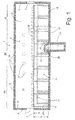
- an oven is shown in the form of a Hubbalkenofens, in FIG. 1 in its entirety is designated by the reference numeral 1.
- the furnace 1 has a substantially tunnel-shaped furnace chamber 3 for receiving metal goods.
- the furnace 1 On one - in FIG. 1
- the furnace 1 On the right-hand side, the furnace 1 has an inlet side 5 with a furnace inlet 7, through which metal goods to be heated in the furnace chamber 3 can be introduced into the furnace chamber 3.
- the furnace 1 On its opposite - in FIG. 1
- the furnace 1 On its opposite - in FIG. 1
- the furnace 1 On the left side, the furnace 1 has an outlet side 9 with a furnace outlet 11, through which metal goods heated in the furnace chamber 3 can be carried out from the furnace chamber 3.
- Between the Input side 5 and the output side 9 of the furnace chamber 3 is bounded on the upper side by a ceiling 13 and the bottom by a furnace bottom 15.
- the side of the furnace chamber 3 between the input side 5 and the output side 9 is bounded by two side walls which extend substantially parallel to the plane of the drawing and of which FIG. 1 only the side wall facing away from the plane of the drawing 16 is marked, while the side wall facing the plane of the drawing is not shown.
- the furnace chamber 3 is divided into three zones, namely an adjoining the input side 5 input zone 3E, one in the transport direction of the metal goods 25 adjoining the heating zone 3H and it in the transport direction of the metal goods 25 adjoining compensation zone 3A, extending to the output side 9 extends.
- the transport system for conveying metal goods 25 through the furnace chamber 3 comprises on the one hand a fixed system of vertical beams and horizontal support tubes 23 on which metal goods 25 conveyed through the furnace chamber 3 can be placed. Furthermore, the transport system comprises a lifting system 27, by means of which the metal goods 25, as known from the prior art, can be lifted off the fixed system 23, can be conveyed one piece in the direction of the exit side 9 and can then be deposited again onto the fixed system 23.
- the fixed system 23 defines a plane E, along which the metal goods 25 can be guided through the furnace chamber 3.
- the transport level 3 divides the furnace space 3 into an upper furnace 3o and a lower furnace 3u.
- the furnace 1 For firing the upper furnace 3o in the region of the heating zone 3H, the furnace 1 has ceiling burner 19, which are arranged on the ceiling 13 in the region of the heating zone 3H.
- the furnace 1 for firing the upper furnace 3o in the region of the heating zone 3H could alternatively also have side burners 21 which would be arranged in the region of the side walls and of which FIG. 1 only the side burner 21 which can be arranged in the region of the illustrated side wall 16 are shown in dashed lines.
- the furnace 1 For firing the upper furnace 3o in the area of the compensation zone 3A, the furnace 1 has front burners 17 arranged in the upper area of the exit side 9.
- the furnace 1 For firing the lower furnace 3u in the area of the compensation zone 3A, the furnace 1 has front burners 10 arranged in the lower area of the exit side 9.
- further burners 29 are arranged in the region of the furnace bottom 15. These further burners 29 are aligned with the output side 9, so that flames extending parallel to the output side 9 can be formed through the burners 29.
- the further burners 29 are arranged along a path which runs in the region of the furnace bottom 15 parallel to the exit side 9 and perpendicular to the plane of the drawing, so that of the further burners 29 in FIG FIG. 1 only a single burner is recognizable.
- the furnace bottom 15 forms on its side facing the furnace chamber 3 from a horizontal plane, the horizontal course is not affected by the other burner 29.
- the further burners 29 are arranged in a housing 30 of a high alumina, refractory material and thereby effectively protected from the hot furnace atmosphere.
- exhaust gas supply means 31 are formed in the form of openings which are arranged on the burner output of the burner 29 opposite side of the housing 30. Exhaust gas from the region of the lower furnace chamber 3u between the further burners 29 and the input side 5 of the furnace 3 can thus be discharged through the openings 31 and can be supplied to the further burners 29, so that this exhaust gas can be post-combusted by the further burners 29.
- the height H of the lower furnace space 3u, so the distance between the transport plane E and the furnace bottom 15, is about 2.5 meters.
- the distance A between the top of the housing 30 and the transport plane E is about 1.3 meters and thus 52% of the height H of the lower furnace chamber 3u.
- the distance A remaining between the underside of the transport plane E and the top of the housing 30 is thus high enough to produce exhaust gases without relevant flow resistance from the area of the compensation zone 3A and the heating zone 3H in the direction of the inlet side 5 and thus through the inlet zone 3E of the furnace 1 to be allowed to flow.
- the furnace 1 also has a walk-in control channel 33, from which the other burner 29 can be operated.
- the control channel 33 is disposed substantially below the furnace bottom 15 and has only the head side access to the housing 30, so that the burner 29 from the control channel 33 are operated and maintained.
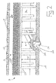
- FIG. 2 shows a highly schematic perspective view of the furnace 1 according to the embodiment according to FIG. 1 in the area of the other burner 29.
- the illustration is after FIG. 1 not to scale for illustration FIG. 1 ,
- FIG. 2 In particular, it is easy to see the elongated course of the housing 30, which extends transversely to the longitudinal course of the furnace 1 over the furnace bottom 15.
Landscapes
- Engineering & Computer Science (AREA)
- Chemical & Material Sciences (AREA)
- Mechanical Engineering (AREA)
- General Engineering & Computer Science (AREA)
- Physics & Mathematics (AREA)
- Thermal Sciences (AREA)
- Crystallography & Structural Chemistry (AREA)
- Materials Engineering (AREA)
- Metallurgy (AREA)
- Organic Chemistry (AREA)
- Tunnel Furnaces (AREA)
Abstract
Die Erfindung betrifft einen Ofen zum Erwärmen von Metallgütern.The invention relates to a furnace for heating metal goods.
Description
Die Erfindung betrifft einen Ofen zum Erwärmen von Metallgütern.The invention relates to a furnace for heating metal goods.
Öfen zum Erwärmen von Metallgütern sind in Form von Wärm- und Wärmebehandlungsöfen für Metallhalbzeuge oder für Rohre aus Stahl oder Nichteisenmetallen bekannt. In solchen Öfen werden die entsprechenden Metallgüter für eine nachfolgende Warmverformung, zur Abschreckung oder zur Durchführung eines Wärmeprozesses im Ofen erwärmt.Furnaces for heating metal goods are known in the form of heat and heat treatment furnaces for semi-finished metal products or for pipes made of steel or non-ferrous metals. In such furnaces, the respective metal goods are heated for subsequent hot working, quenching, or furnace heating.
Unter Metallgütern werden hierin demnach Metallhalbzeuge oder Metallrohre verstanden. Metallhalbzeuge können insbesondere Knüppel, Blöcke oder Brammen sein.Metal goods are hereby understood to mean semis or metal pipes. Semi-finished metal products may in particular be billets, blocks or slabs.
Verbreitete Ausführungsformen solcher Öfen zum Erwärmen von Metallgütern sind Stoßöfen und Hubbalkenöfen.Common embodiments of such ovens for heating metal goods are pushers and Hubbalkenöfen.
Bei Stoßöfen liegen die Metallgüter im Ofenraum auf Schienen auf und werden mittels einer Stoßmaschine durch den Ofen gestoßen. Dabei liegen die einzelnen Metallgüter fest aneinander, so dass die Stoßmaschine beim Einschieben eines neuen Metallgutes gleichzeitig den ganzen Ofeninhalt weiterschiebt.In the case of pushers, the metal goods lie in the furnace chamber on rails and are pushed through the furnace by means of a slotting machine. In this case, the individual metal goods are firmly together, so that the impact machine pushes on the insertion of a new metal good at the same time the whole contents of the furnace.
Bei einem Hubbalkenofen umfasst das Fördersystem zur Förderung der Metallgüter durch den Ofenraum zwei Arten von Rohren oder Balken. Die eine Art dieser Rohre oder Balken, die auch als Festsysteme (die horizontale und vertikale Rohre und/oder Balken umfassen) bezeichnet werden, sind unbeweglich und dienen zur Auflage der Metallgüter. Die zweite Art der Rohre oder Balken, die auch als Hubsysteme (die wiederum horizontale und vertikale Rohre und/oder Balken umfassen) bezeichnet werden, bewegen sich zwischen den Festsystemen auf und ab und beschreibend dabei eine einem Kreis oder einem Rechteck angenäherte Bahn. Bei jeder dieser Bahnbewegungen werden auf den Festsystemen aufliegende Metallgüter durch die Hubsysteme angehoben, ein Stück fortbewegt und anschließend wieder auf den Festsystemen abgelegt.In a walking beam furnace, the conveying system for conveying the metal goods through the furnace space comprises two types of pipes or beams. One type of these pipes or beams, which are also referred to as fixed systems (comprising horizontal and vertical pipes and / or beams), are immovable and serve to support the metal goods. The second type of tubes or beams, also referred to as hoisting systems (which in turn comprise horizontal and vertical tubes and / or beams), move up and down between the fixed systems, describing a path approximating a circle or a rectangle. During each of these orbital movements, metal goods resting on the fixed systems are lifted by the lifting systems, moved one step and then deposited again on the fixed systems.
Entsprechend ausgebildete Öfen zum Erwärmen von Metallgütern, insbesondere Stoßöfen und Hubbalkenöfen, weisen in der Regel einen Ofenraum mit einer im Wesentlichen tunnelartigen Form auf, also mit einer Eingangsseite auf der einen Seite und einer Ausgangsseite auf der gegenüberliegenden Seite des Ofenraums. Zur Befeuerung des Ofenraums sind oberhalb der Transportebene der durch den Ofenraum zu transportierten Metallgüter (dem sogenannten "Oberofen") an der Decke des Ofens Deckenbrenner und/oder an den Seitenwänden des Ofens Seitenbrenner angeordnet. Unterhalb der Transportebene der durch den Ofenraum zu transportierten Metallgüter (dem sogenannten "Unterofen") sind an den Seitenwänden des Ofens Seitenbrenner angeordnet. Da in der Ausgleichzone des Ofens, also in dem der Ausgangsseite benachbarten Bereich des Ofenraumes, regelmäßig eine zusätzliche Befeuerung des Ofenraumes gewünscht ist, sind im Bereich der Ausgangsseite regelmäßig weitere Brenner, sogenannte Stirnbrenner, im Ober- und/oder im Unterofen an der Stirnwand des Ofens angeordnet.Appropriately designed ovens for heating metal goods, in particular pushers and Hubbalkenöfen, usually have a furnace chamber with a substantially tunnel-like shape, ie with an input side on one side and an output side on the opposite side of the furnace chamber. For firing the furnace chamber above the transport plane to be transported through the furnace chamber metal goods (the so-called "upper furnace") on the ceiling of the furnace ceiling burner and / or arranged on the side walls of the furnace side burner. Below the transport level of the by the Furnace space to transported metal goods (the so-called "sub-furnace") are arranged on the side walls of the furnace side burner. Since in the balancing zone of the furnace, ie in the region adjacent to the output side of the furnace chamber, an additional firing of the furnace chamber is regularly desired, more burners, so-called face burners, in the top and / or bottom furnace at the end wall of the Furnace arranged.
Öfen zum Erwärmen von Metallgütern sind üblicherweise in wenigstens drei Zonen aufgeteilt, und zwar in eine Eingangszone (die im Stand der Technik auch als "Konvektivzone" bezeichnet wird), eine Heizzone und eine Ausgleichzone.Furnaces for heating metal goods are usually divided into at least three zones, namely an entrance zone (which is also referred to in the art as a "convective zone"), a heating zone and a balancing zone.
Die Eingangszone schließt sich unmittelbar an den Ofeneinlass an und dient zur Vorwärmung von in den Ofenraum eingeführten Metallgütern. Die Eingangzone wird in der Regel nicht über Brenner, sondern über die aus der Ausgleich- und Heizzone abgezogenen, heißen Ofenabgase geheizt.The entrance zone immediately adjoins the furnace inlet and serves to preheat metal goods introduced into the furnace chamber. As a rule, the entrance zone is not heated by burners, but by hot furnace exhaust gases extracted from the equalization and heating zone.
An die Eingangszone schließt sich in Transportrichtung der durch den Ofenraum transportierten Metallgüter die Heizzone an. In dieser findet die wesentliche Erhitzung beziehungsweise Wärmebehandlung der Metallgüter im Ofenraum statt. Hierzu wird die Heizzone im Oberofen mit Seiten- oder Deckenbrennern und im Unterofen mit Seitenbrennern befeuert. Da eine Befeuerung des Oberofens in der Heizzone des Ofenraums über Seitenbrenner in der Regel einfacher und kostengünstiger ist als eine Befeuerung über Deckenbrenner, wird in der Heizzone möglichst über Seitenbrenner geheizt. Allerdings ist dies nur bis zu einer maximalen Ofenbreite möglich, da ab einer bestimmten Ofenbreite eine ausreichend gleichmäßige Temperaturverteilung über die gesamte Ofenbreite mit Seitenbrennern nicht mehr zu erreichen ist. Daher wird ab einer bestimmten Ofenbreite der Oberofen der Heizzone über Deckenbrenner befeuert, da mit Deckenbrennern eine gleichmäßige Temperaturverteilung über die gesamte Ofenbreite zu erreichen ist. Im Unterofen kann durch die Deckenbrenner eine gleichmäßige Temperaturverteilung jedoch nicht hergestellt werden.The heating zone adjoins the input zone in the transport direction of the metal goods transported through the furnace chamber. In this takes place the essential heating or heat treatment of the metal goods in the furnace chamber. For this purpose, the heating zone is fired in the upper furnace with side or ceiling burners and in the lower furnace with side burners. Since a firing of the furnace in the heating zone of the furnace chamber via side burner is usually easier and less expensive than firing on ceiling burner, is heated in the heating zone as possible on side burner. However, this is only possible up to a maximum width of the oven, as from a certain Furnace width a sufficiently uniform temperature distribution over the entire width of the furnace with side burners can no longer be achieved. Therefore, starting at a certain width of the furnace furnace of the heating zone is fired by ceiling burner, as with ceiling burners a uniform temperature distribution over the entire width of the furnace can be achieved. In the lower furnace, however, a uniform temperature distribution can not be produced by the ceiling burners.
An die Heizzone schließt sich in Transportrichtung der durch den Ofenraum transportierten Metallgüter schließlich die Ausgleichzone an, die sich bis zum Ofenauslass erstreckt. In der Ausgleichzone wird der Oberofen in der Regel über Decken-, Seiten- oder Stirnbrenner und der Unterofen über Seiten- oder Stirnbrenner befeuert.In the transport direction of the transported through the furnace chamber metal goods finally connects to the heating zone, the compensation zone, which extends to the furnace outlet. In the balancing zone, the upper furnace is usually fired via ceiling, side or front burners and the lower furnace via side or front burners.
Grundsätzlich haben sich entsprechend ausgebildete Öfen zum Erwärmen von Metallgütern bewährt. Häufig ist jedoch eine gleichmäßigere Temperaturverteilung im Unterofen in der Heizzone gattungsgemäßer Erwärmungsöfen gewünscht, als dies mit den Seitenbrennern nach dem Stand der Technik möglich ist. Dies gilt insbesondere bei Öfen großer Breite beziehungsweise bei der Erwärmung von Metallgütern großer Länge, die in entsprechend breiten Öfen erwärmt werden müssen.Basically, appropriately trained ovens for heating metal goods have been proven. Often, however, a more uniform temperature distribution in the sub-furnace in the heating zone of generic heating furnaces is desired than is possible with the side burners of the prior art. This is especially true in furnaces of large width or in the heating of metal goods of great length, which must be heated in accordance broad ovens.
Der Erfindung liegt die Aufgabe zugrunde, einen Ofen zum Erwärmen von Metallgütern zur Verfügung zu stellen, durch den eine verbesserte Befeuerung der Heizzone des Ofens möglich ist. Insbesondere soll es möglich sein, im Unterofen der Heizzone des Ofens eine gleichmäßigere Temperaturverteilung als in Öfen nach dem Stand der Technik zu schaffen, und zwar insbesondere bei Öfen einer großen Breite.The invention has for its object to provide a furnace for heating metal goods available by the improved firing of the heating zone of the furnace is possible. In particular, it should be possible to provide a more uniform temperature distribution in the lower furnace of the heating zone of the furnace than in furnaces according to the prior art, in particular in furnaces of a large width.
Zur Lösung dieser Aufgabe wird erfindungsgemäß zur Verfügung gestellt ein Ofen zum Erwärmen von Metallgütern mit folgenden Merkmalen:
- einem zur Aufnahme von Metallgütern ausgebildeten Ofenraum;
- einer Eingangsseite mit einem Ofeneinlass, durch den im Ofenraum zu erwärmende Metallgüter in den Ofenraum einführbar sind;
- einer Ausgangsseite mit einem Ofenauslass auf, durch den im Ofenraum erwärmte Metallgüter aus dem Ofenraum ausführbar sind;
- einer Decke, die den Ofenraum zwischen der Eingangsseite und Ausgangsseite oberseitig begrenzt;
- einem Ofenboden, der den Ofenraum zwischen der Eingangsseite und der Ausgangsseite unterseitig begrenzt;
- Seitenwänden, die den Ofenraum zwischen der Eingangsseite und der Ausgangsseite seitlich begrenzen;
- Brennern zur Befeuerung des Ofenraums, wobei die Brenner wenigstens eine der folgenden Arten von Brennern umfassen: im Bereich der Decke angeordnete Deckenbrenner oder im Bereich der Seitenwände angeordnete Seitenbrenner;
- weiteren Brennern zur Befeuerung des Ofenraums, die im Bereich des Ofenbodens angeordnet sind.
- a furnace space formed for receiving metal goods;
- an inlet side with a furnace inlet through which metal goods to be heated in the furnace chamber can be introduced into the furnace chamber;
- an outlet side with a furnace outlet, through which heated in the furnace chamber metal goods from the furnace chamber are executable;
- a ceiling which delimits the furnace space between the input side and the output side;
- a furnace bottom, which delimits the furnace space between the inlet side and the outlet side;
- Side walls that laterally delimit the furnace space between the input side and the output side;
- Burners for firing the furnace chamber, the burners comprising at least one of the following types of burners: ceiling-mounted ceiling burners or side burners arranged in the region of the side walls;
- further burners for firing the furnace chamber, which are arranged in the region of the furnace bottom.
Die Grundidee der Erfindung besteht darin, den Ofenraum des Ofens durch weitere Brenner zu befeuern, die im Bereich des Ofenbodens angeordnet sind (hierin als "weitere Brenner" bezeichnet). Da die weiteren Brenner im Bereich des Ofenbodens angeordnet sind, ist durch die weiteren Brenner der Unterofen des erfindungsgemäßen Ofens befeuerbar. Da die Anordnung der weiteren Brenner im Bereich der Heizzone des Unterofens - im Gegensatz zu den nach dem Stand der Technik verwendeten Seitenbrennern zur Befeuerung des Unterofens im Bereich der Heizzone - nicht auf die Seitenwände beschränkt ist, sondern die weiteren Brenner vielmehr über die gesamte Ofenbreite hinweg im Bereich des Ofenbodens in der Heizzone des Ofens angeordnet sein können, ist der Unterofen im Bereich der Heizzone des erfindungsgemäßen Ofens durch die erfindungsgemäß vorgesehenen weiteren Brenner über die gesamte Ofenbreite hinweg befeuerbar. Hierdurch ist eine wesentlich gleichmäßigere Temperaturverteilung in der Heizzone im Bereich des Unterofens erreichbar als bei Öfen nach dem Stand der Technik, die in der Heizzone nur durch Seitenbrenner befeuerbar sind.The basic idea of the invention is to fire the furnace chamber of the furnace by means of further burners arranged in the region of the furnace bottom (referred to herein as "further burners"). Since the other burners are arranged in the region of the furnace bottom, the lower furnace of the furnace according to the invention can be fired by the further burners. Since the arrangement of the other burners in the region of the heating zone of the lower furnace - in contrast to the side burners used in the prior art for firing the furnace in the heating zone - is not limited to the side walls, but the further burners can rather be arranged over the entire width of the oven in the region of the furnace bottom in the heating zone of the furnace, the lower furnace in the region of the heating zone of the furnace according to the invention can be ignited by the further burners provided according to the invention over the entire width of the furnace. As a result, a much more uniform temperature distribution in the heating zone in the area of the lower furnace can be achieved than in furnaces according to the prior art, which are only fueled by side burners in the heating zone.
Der erfindungsgemäße Ofen weist bevorzugt eine Eingangszone, eine Heizzone sowie eine Ausgleichzone auf. Diese Zonen können jeweils, wie aus dem Stand der Technik bekannt und wie zuvor beschrieben ausgebildet sein, wobei der Unterofen - im Gegensatz zum Stand der Technik - bei einem erfindungsgemäßen Ofen zusätzlich durch die weiteren Brenner befeuerbar ist.The furnace according to the invention preferably has an input zone, a heating zone and a compensation zone. These zones can each be formed, as known from the prior art and as described above, wherein the lower furnace - in contrast to the prior art - in a furnace according to the invention is additionally fueled by the other burner.
Bevorzugt sind die weiteren Brenner im Bereich der Heizzone des erfindungsgemäßen Ofens angeordnet. Nach einer Ausführungsform ist vorgesehen, dass die weiteren Brenner ausschließlich im Bereich der Heizzone des Ofens angeordnet sind.The further burners are preferably arranged in the region of the heating zone of the furnace according to the invention. According to one embodiment, it is provided that the further burners are arranged exclusively in the region of the heating zone of the furnace.
Die Brenner sind bevorzugt nicht nach oben, also in Richtung auf das im Ofen zu erwärmende Gut, sondern bevorzugt in wenigstens einer der folgenden Richtungen hin ausgerichtet: in Richtung auf die Ausgangsseite oder in Richtung auf die Eingangsseite des Ofens. Hierdurch lässt sich eine besonders gleichmäßige Temperaturverteilung erreichen. Die Gleichmäßigkeit der Temperaturverteilung lässt sich noch weiter dadurch steigern, dass die jeweils in eine Richtung ausgerichteten weiteren Brenner jeweils parallel zueinander ausgerichtet sind, so dass die durch die weiteren Brenner in eine Richtung erzeugten Flammen beziehungsweise Brennergasstrahle parallel zueinander verlaufen.The burners are preferably not oriented upwards, ie in the direction of the material to be heated in the oven, but preferably in at least one of the following directions: in the direction of the outlet side or in the direction of the inlet side of the oven. This makes it possible to achieve a particularly uniform temperature distribution. The uniformity of the temperature distribution can be further increased by the fact that each aligned in one direction Further burners are each aligned parallel to each other, so that the flame produced by the other burner in one direction or burner gas jet parallel to each other.
Da die weiteren Brenner im Bereich des Ofenbodens angeordnet sind, wird der Ofenbetrieb, insbesondere die Abgasführung sowie der Transport der Güter durch den Ofen, durch die weiteren Brenner nicht negativ beeinflusst.Since the other burners are arranged in the region of the furnace bottom, the furnace operation, in particular the exhaust gas routing and the transport of the goods through the furnace, is not adversely affected by the other burner.
So ist es beispielsweise nicht notwendig, dass der Ofenboden eines erfindungsgemäßen Ofens in besonderer Weise gestaltet ist, um die weiteren Brenner aufzuweisen. Beispielsweise kann der Ofenboden eines erfindungsgemäßen Ofens im wesentlichen in Form einer horizontalen Ebene ausgebildet sein. Dies erlaubt eine besonders gleichmäßige Flammen- und Abgasführung im Unterofen.For example, it is not necessary that the furnace bottom of a furnace according to the invention is designed in a special way to have the other burner. For example, the furnace bottom of a furnace according to the invention may be formed substantially in the form of a horizontal plane. This allows a particularly uniform flame and exhaust gas in the lower furnace.
Bei dem erfindungsgemäßen Ofen kann es sich insbesondere um einen solchen in Form eines Stoßofens oder Hubbalkenofens handeln. Insoweit kann der erfindungsgemäße Ofen die aus dem Stand der Technik bekannten Merkmale eines Stoßofens oder Hubbalkenofens aufweisen.The furnace according to the invention may in particular be one in the form of a pusher or walking beam furnace. In that regard, the furnace according to the invention may comprise the known from the prior art features of a pusher or Hubbalkenofens.
Der erfindungsgemäße Ofen ist zum Erwärmen von Metallgütern, insbesondere von Metallgütern großer Länge - beispielsweise in Form von Stahlhalbzeugen, beispielsweise in Form von Knüppeln, Blöcken oder Brammen oder beispielsweise in Form von Metallrohren - ausgebildet.The furnace according to the invention is designed for heating metal goods, in particular metal goods of great length, for example in the form of semi-finished steel products, for example in the form of billets, blocks or slabs or for example in the form of metal pipes.
Der erfindungsgemäße Ofen und dessen Ofenraum kann grundsätzlich eine beliebige Größe und Dimension aufweisen. Insbesondere kann es sich bei einem erfindungsgemäßem Ofen jedoch um einen Ofen mit einer großen Breite des Ofenraums handeln, da insbesondere bei Öfen großer Breite die vorteilhafte Wirkung der weiteren Brenner, die eine besonders gleichmäßige Temperaturverteilung im Unterofen - insbesondere im Bereich der Heizzone des Unterofens - erlauben, zum Tragen kommt.The furnace according to the invention and the furnace chamber can in principle have any size and dimension. In particular, it can However, an oven according to the invention is an oven having a large width of the oven space, since the advantageous effect of the further burners, which allow a particularly uniform temperature distribution in the lower furnace, in particular in the area of the heating zone of the furnace, is particularly important for furnaces of large width comes.
Die Breite des Ofenraums des erfindungsgemäßen Ofens, also der durchschnittliche Abstand zwischen den Seitenwänden, kann beispielsweise mehr als 15 Meter betragen.The width of the furnace chamber of the furnace according to the invention, that is to say the average distance between the side walls, can be for example more than 15 meters.
Der Ofenraum eines erfindungsgemäßen Ofens kann beispielsweise eine Länge von 13 Meter und mehr aufweisen, wobei als Länge des Ofens die kürzeste Distanz im Ofenraum zwischen Ofeneinlass und Ofenauslass verstanden wird.The furnace chamber of a furnace according to the invention may, for example, have a length of 13 meters and more, the length of the furnace being understood to be the shortest distance in the furnace space between the furnace inlet and the furnace outlet.
Sämtliche Brenner des erfindungsgemäßen Ofens können gemäß den aus dem Stand der Technik bekannten Ausführungsformen für Brenner ausgebildet sein. Beispielsweise kann es sich bei den Brennern um Hochgeschwindigkeitsbrenner oder Impulsbrenner handeln.All burners of the furnace according to the invention can be designed according to the burner embodiments known from the prior art. For example, the burners may be high speed burners or pulse burners.
Die Stirn-, Decken- und Seitenbrenner des erfindungsgemäßen Ofens können gemäß dem Stand der Technik angeordnet sein. Insofern kann beispielsweise vorgesehen sein, dass der Ofen im Bereich seiner Eingangszone keine Brenner aufweist. Im Bereich der Heizzone kann der Ofen beispielsweise entweder Decken- oder Seitenbrenner zur Befeuerung des Oberofens aufweisen; soweit der erfindungsgemäße Ofen eine große Breite aufweist, kann vorgesehen sein, dass dieser im Bereich der Heizzone ausschließlich Deckenbrenner zur Befeuerung des Oberofens aufweist. Zur Befeuerung des Unterofens kann der Ofen im Bereich der Heizzone bevorzugt ausschließlich die weiteren Brenner aufweisen. Im Bereich der Ausgleichzone kann der erfindungsgemäße Ofen bevorzugt Decken-, Seiten- oder Stirnbrenner zur Befeuerung des Oberofens aufweisen; bevorzugt weist der Ofen ausschließlich eine dieser drei Arten von Brennern zur Befeuerung des Oberofens im Bereich der Ausgleichzone auf. Zur Befeuerung des Unterofens im Bereich der Ausgleichzone kann der Ofen Seiten- oder Stirnbrenner aufweisen; soweit der erfindungsgemäße Ofen eine große Breite aufweist, kann vorgesehen sein, dass dieser im Bereich der Ausgleichzone ausschließlich Stirnbrenner zur Befeuerung des Unterofens aufweist.The face, ceiling and side burners of the furnace according to the invention may be arranged according to the prior art. In this respect, it may be provided, for example, that the furnace has no burners in the region of its input zone. In the area of the heating zone, for example, the furnace may have either ceiling or side burners for firing the top furnace; If the furnace according to the invention has a large width, it can be provided that it has exclusively ceiling burner in the area of the heating zone for firing the upper furnace. For firing the furnace, the stove can be used in the Area of the heating zone preferably exclusively have the other burner. In the area of the compensation zone, the furnace according to the invention may preferably have ceiling, side or end burners for firing the top furnace; Preferably, the furnace has only one of these three types of burners for firing the furnace in the area of the compensation zone. For firing the furnace in the area of the equalization zone, the furnace may have side or front burners; As far as the furnace according to the invention has a large width, it can be provided that this has in the region of the equalization zone only forehead burner for firing the furnace.
Der Ofen kann insbesondere derart ausgebildet sein, dass der Ofenraum, insbesondere im Bereich der Heizzone, auf Temperaturen im Bereich von 500°C bis 1.300°C beheizbar ist. Soweit der Ofen zum Erwärmen von Metallrohren oder von Halbzeugen für Metallrohre dient, kann der Ofenraum beispielsweise auf Temperaturen im Bereich von 500°C bis 1.050°C beheizbar sein; zum Erwärmen von sonstigen Metallhalbzeugen, beispielsweise in Form von Knüppeln, Blöcken oder Brammen, kann der Ofenraum beispielsweise auf Temperaturen im Bereich von 950°C bis 1.300°C beheizbar sein.The furnace may in particular be designed such that the furnace space, in particular in the region of the heating zone, can be heated to temperatures in the range from 500.degree. C. to 1300.degree. As far as the furnace is used for heating metal pipes or semi-finished products for metal pipes, the furnace space can be heated, for example, to temperatures in the range of 500 ° C to 1050 ° C; for heating other metal semi-finished products, for example in the form of billets, blocks or slabs, the furnace chamber, for example, be heated to temperatures in the range of 950 ° C to 1,300 ° C.
Wie aus dem Stand der Technik bekannt, arbeitet der Ofen bevorzugt im Gegenstromprinzip, wobei die Metallgüter vom Ofeneinlass in Richtung Ofenauslass geführt wird und die Abgase, die in der Ausgleich- und Heizzone erzeugt werden, in der entgegengesetzten Bewegungsrichtung in Richtung Ofeneinlass geführt und von dort aus dem Ofenraum abgezogen werden. Im Bereich der Eingangszone des Ofens wird ein Teil der in den Abgasen enthaltenen Wärmeenergie an die in den Ofen eingeführten Metallgüter übertragen und hierdurch eine Vorwärmung der in den Ofenraum eingeführten Metallgüter erreicht.As is known in the art, the furnace preferably operates countercurrently, with the metal goods being directed from the furnace inlet towards the kiln outlet and the exhaust gases generated in the balancing and heating zone being directed in the opposite direction of movement towards the kiln inlet and thence be removed from the oven room. In the area of the entrance zone of the furnace, part of the heat energy contained in the exhaust gases is transferred to the furnace transferred imported metal goods and thereby achieved a preheating of imported into the furnace chamber metal goods.
Der erfindungsgemäße Ofen kann eine aus dem Stand der Technik bekannte Vorrichtung zum Transport beziehungsweise zur Führung der Metallgüter durch den Ofenraum aufweisen. Soweit der erfindungsgemäße Ofen als Stoßofen ausgebildet ist, kann der Ofen demnach eine Stoßvorrichtung und, soweit der Ofen als Hubbalkenofen ausgebildet ist, eine entsprechende Hubvorrichtung zum Transport der Metallgüter durch den Ofenraum aufweisen.The furnace according to the invention may comprise a device known from the prior art for transporting or guiding the metal goods through the furnace chamber. As far as the oven according to the invention is designed as a blast furnace, the oven can therefore a shock device and, as far as the furnace is designed as Hubbalkenofen, have a corresponding lifting device for transporting the metal goods through the furnace chamber.
Die weiteren Brenner des erfindungsgemäßen Ofens können beispielsweise unmittelbar im Bereich des Ofenbodens angeordnet sein, beispielsweise nach Art und Weise der aus dem Stand der Technik bekannten Decken-, Seiten- oder Stirnbrenner. Um die weiteren Brenner jedoch gezielt in Richtung Ofenein- oder Ofenauslass ausrichten zu können, kann vorgesehen sein, die weiteren Brenner in wenigstens einem im Bereich des Ofenbodens angeordneten Gehäuse anzuordnen. Die weiteren Brenner können derart in diesem wenigstens einen Gehäuse angeordnet sein, dass sie durch das Gehäuse vor der heißen Ofenatmosphäre geschützt sind, jedoch gleichzeitig noch gezielt ausgerichtet werden können, insbesondere gezielt in Richtung Ofenein-oder Ofenauslass ausgerichtet werden können. Diese Gehäuse können beispielsweise aus einem feuerfesten keramischen Werkstoff gebildet sein, beispielsweise aus einem hochtonerdehaltigen feuerfesten Werkstoff.The further burners of the furnace according to the invention can be arranged, for example, directly in the region of the furnace bottom, for example in the manner of the ceiling, side or face burners known from the prior art. However, in order to be able to align the further burners in the direction of the kiln inlet or kiln outlet, it is possible to arrange the further burners in at least one housing arranged in the region of the kiln floor. The further burners can be arranged in this at least one housing in such a way that they are protected by the housing from the hot furnace atmosphere, but at the same time they can still be specifically aligned, in particular can be aligned specifically in the direction of the furnace inlet or furnace outlet. These housings may for example be formed of a refractory ceramic material, for example of a high alumina refractory material.
Nach einer Ausführungsform kann beispielsweise vorgesehen sein, dass jeweils einer oder eine Anzahl von weiteren Brennern in jeweils einem Gehäuse angeordnet sind, wobei beispielsweise mehrere dieser Gehäuse beabstandet zueinander im Bereich des Ofenbodens angeordnet sein können. Beispielweise kann auch vorgesehen sein, dass sämtliche weiteren Brenner in einem einzigen Gehäuse angeordnet sind.According to one embodiment, for example, it can be provided that in each case one or a number of further burners in each case one Housing are arranged, for example, a plurality of these housings spaced from one another in the region of the furnace bottom can be arranged. For example, it can also be provided that all further burners are arranged in a single housing.
Grundsätzlich können die weiteren Brenner an beliebigen Positionen im Bereich des Ofenbodens angeordnet sein. Bevorzugt können die weiteren Brenner jedoch über die gesamte Breite des Ofenbodens hinweg im Bereich des Ofenbodens angeordnet sein, insbesondere über die gesamte Breite des Ofenbodens hinweg im Bereich der Heizzone des Ofens.In principle, the further burners can be arranged at arbitrary positions in the region of the furnace bottom. However, the further burners may preferably be arranged over the entire width of the furnace bottom in the region of the furnace bottom, in particular over the entire width of the furnace bottom in the region of the heating zone of the furnace.
Die weiteren Brenner können beispielsweise im Wesentlichen entlang einer Strecke angeordnet sein, die sich im Wesentlichen parallel zum Ofenauslass im Bereich des Ofenbodens erstreckt. Beispielsweise können die weiteren Brenner gleichmäßig voneinander beabstandet entlang einer solchen Strecke im Bereich des Ofenbodens angeordnet sein, beispielsweise von der einen Seitenwand bis zur anderen Seitenwand, bevorzugt über die gesamte Breite des Ofenbodens hinweg. Soweit die weiteren Brenner in wenigstens einem der vorgenannten Gehäuse angeordnet sind, können sich das oder die Gehäuse beispielsweise ebenfalls entlang einer solchen Strecke erstrecken, beispielsweise von der einen bis zur anderen Seitenwand.The further burners may, for example, be arranged essentially along a path which extends substantially parallel to the furnace outlet in the region of the furnace bottom. For example, the further burners may be arranged uniformly spaced along such a distance in the region of the furnace bottom, for example from one side wall to the other side wall, preferably over the entire width of the furnace bottom. As far as the other burners are arranged in at least one of the aforementioned housing, the housing or the housing, for example, also extend along such a distance, for example, from one to the other side wall.
Wie aus dem Stand der Technik bekannt, können die Metallgüter im Bereich einer Ebene durch den Ofenraum transportiert werden. Diese Transportebene kann durch Auflagemittel definiert sein, auf denen die Güter während des Transports durch den Ofen aufliegen. Soweit der Ofen als Stoßofen ausgebildet ist, können diese Auflagemittel beispielsweise Schienen oder dergleichen Mittel sein, auf denen die Güter aufliegen, während sie durch die Stoßmaschine durch den Ofenraum gestoßen werden. Diese Schienen können, wie aus dem Stand der Technik bekannt, wassergekühlt und durch feuerfeste keramische Massen gegenüber der Ofenatmosphäre geschützt sein. Beispielsweise können auch ungekühlte Schienen aus hitzebeständigem Stahl Anwendung finden.As known from the prior art, the metal goods can be transported in the region of a plane through the furnace chamber. This transport plane may be defined by support means on which the goods rest during transport through the furnace. As far as the furnace is designed as a blast furnace, these support means may be, for example, rails or similar means on which the goods rest, while being pushed through the furnace room by the impact machine. As is known in the art, these rails can be water-cooled and protected from the furnace atmosphere by refractory ceramic masses. For example, non-cooled rails made of heat-resistant steel can be used.
Soweit der Ofen als Hubbalkenofen ausgebildet ist, kann die Transportebene, entlang derer die Metallgüter durch den Ofenraum transportiert werden, beispielsweise durch die Ebene definiert sein, in der sich die Metallgüter befinden, wenn sie auf den Festsystemen aufliegen. Die Festsysteme und Hubsysteme des Hubbalkenofens können ebenfalls wie aus dem Stand der Technik bekannt ausgebildet sein, also wiederum beispielsweise als wassergekühlte Rohre oder Schienen, die gegenüber der Ofenatmosphäre durch eine feuerfeste keramische Masse geschützt sein können. Beispielsweise können auch ungekühlte Fest- und Hubsysteme aus hitzebeständigem Stahl Anwendung finden.As far as the oven is designed as Hubbalkenofen, the transport plane, along which the metal goods are transported through the oven chamber, for example, be defined by the plane in which the metal goods are when they rest on the fixed systems. The fixed systems and lifting systems of the walking beam furnace can also be designed as known from the prior art, in turn, for example, as water-cooled pipes or rails, which may be protected from the furnace atmosphere by a refractory ceramic mass. For example, non-cooled stationary and lifting systems made of heat-resistant steel can be used.
Vor diesem Hintergrund kann der erfindungsgemäße Ofen beispielsweise die folgenden weiteren Merkmale aufweisen:
- eine Ebene, entlang derer im Ofenraum zu erwärmende Metallgüter durch den Ofenraum führbar sind, wobei die Ebene den Ofenraum in einen zwischen der Ebene und der Decke liegenden oberen Ofenraum ("Oberofen") und einen zwischen der Ebene und dem Ofenboden liegenden unteren Ofenraum ("Unterofen") unterteilt;
- wenigstens ein Gehäuse, in dem die weiteren Brenner angeordnet sind;
- der zwischen der Oberseite des wenigstens einen Gehäuses und der Unterseite der Ebene befindliche Abstand beträgt wenigstens 40 % der Höhe des unteren Ofenraums.
- a plane along which metal goods to be heated in the furnace chamber can be passed through the furnace space, the plane defining the furnace space in an upper furnace space lying between the plane and the ceiling ("upper furnace") and a lower furnace space lying between the plane and the furnace floor (" Unterofen ") divided;
- at least one housing in which the further burners are arranged;
- the distance between the top of the at least one housing and the bottom of the plane is at least 40% of the height of the lower furnace space.
Indem der Abstand zwischen der Oberseite des oder der Gehäuse und der Unterseite der Ebene wenigstens 40 % der Höhe des unteren Ofenraums beträgt, werden die Abgasführung sowie der Transport der Metallgüter durch den Ofenraum praktisch nicht beeinflusst. Insoweit kann beispielsweise auch vorgesehen sein, dass der zwischen der Oberseite des wenigstens einen Gehäuses und der Unterseite der Ebene befindliche Abstand beträgt wenigstens 50%, 60 %, 70 %, 80% oder auch wenigstens 90% Höhe des unteren Ofenraums beträgt.By the distance between the top of the housing and the bottom of the plane is at least 40% of the height of the lower furnace chamber, the exhaust gas routing and the transport of the metal goods through the furnace chamber are practically not affected. In that regard, for example, be provided that the located between the top of at least one housing and the bottom of the plane distance is at least 50%, 60%, 70%, 80% or at least 90% height of the lower furnace chamber.
Der obere Ofenraum wird fachsprachlich auch als "Oberofen" und der untere Ofenraum als "Unterofen" bezeichnet.The upper furnace chamber is also referred to as "upper furnace" and the lower furnace chamber as "lower furnace".
Unter der Höhe des unteren Ofenraums beziehungsweise der Höhe des Unterofens wird hierin der durchschnittliche Abstand zwischen der Transportebene der Halbzeuge und dem Ofenboden verstanden.The height of the lower furnace space or the height of the lower furnace is understood here to mean the average distance between the transport plane of the semi-finished products and the furnace bottom.
Der Abstand zwischen der Oberseite des wenigstens einen Gehäuses und der Unterseite der Transportebene kann beispielsweise wenigstens 0,5 Meter, 0,7 Meter, 0,9 Meter, 1,0 Meter, 1,1 Meter oder 1,2 Meter betragen. Ferner kann der Abstand zwischen der Oberseite des wenigstens eines Gehäuses und der Unterseite der Transportebene höchstens 2,0 Meter, 1,8 Meter, 1,6 Meter, 1,5 Meter oder 1,4 Meter betragen.The distance between the upper side of the at least one housing and the underside of the transport plane may be for example at least 0.5 meters, 0.7 meters, 0.9 meters, 1.0 meters, 1.1 meters or 1.2 meters. Further, the distance between the top of the at least one housing and the bottom of the transport plane may be at most 2.0 meters, 1.8 meters, 1.6 meters, 1.5 meters or 1.4 meters.
Die Höhe des Unterofens kann beispielsweise im Bereich von 0,8 bis 2,7 Meter liegen.The height of the lower furnace may be, for example, in the range of 0.8 to 2.7 meters.
Erfindungsgemäß hat sich herausgestellt, dass der Ofenbetrieb bei einem entsprechenden Abstand zwischen der Oberseite des wenigstens eines Gehäuses und der Unterseite der Transportebene durch das oder die Gehäuse praktisch nicht beeinflusst wird. Insbesondere wird beispielsweise der freie Querschnitt des Unterofens, der zum Passieren der in der Ausgleichzone und der Heizzone erzeugten heißen Abgase zur Eingangszone benötigt wird, nicht wesentlich verengt.According to the invention, it has been found that the furnace operation is virtually unaffected by the housing (s) at a corresponding distance between the upper side of the at least one housing and the underside of the transport plane. In particular, for example, the free cross-section of the furnace, which is needed to pass the hot exhaust gases generated in the equalization zone and the heating zone to the entry zone, is not significantly narrowed.
Vorteilhaft an einem entsprechend großen Abstand zwischen dem wenigstens einen Gehäuse und der Transportebene ist auch, dass sich etwaig auf den Gehäusen sammelnder Zunder nicht in Kontakt mit den durch den Ofenraum transportierten Metallgütern oder den Hubsystemen treten kann.An advantage of a correspondingly large distance between the at least one housing and the transport plane is also that any scale collecting on the housings can not come into contact with the metal goods or the lifting systems transported through the furnace chamber.
Nach einer Ausführungsform ist vorgesehen, dass der Ofen einen vollständig oder im Wesentlichen unterhalb des Ofenbodens angeordneten Bedienungskanal aufweist, von dem aus die weiteren Brenner bedienbar sind. Der Bedienungskanal kann insbesondere derart ausgebildet sein, dass dieser durch Personal begehbar ist. Beispielsweise kann vorgesehen sein, dass die weiteren Brenner beziehungsweise das oder die Gehäuse, in denen die weiteren Brenner angeordnet sind, kopfseitig vom Bedienungskanal aus zugänglich sind, um die Brenner bedienen oder warten zu können.According to one embodiment, it is provided that the furnace has a completely or substantially arranged below the furnace bottom operating channel, from which the other burner can be operated. The control channel may in particular be designed such that it can be walked on by personnel. For example, it can be provided that the further burners or the housing (s) in which the further burners are arranged are accessible on the head side from the operating channel in order to be able to operate or service the burners.
Nach einer Ausführungsform ist vorgesehen, dass der erfindungsgemäße Ofen Abgaszuleitungsmittel aufweist, durch die den weiteren Brennern Abgase, also Verbrennungsgase der Brenner des Ofens, zuleitbar sind. Solche Abgaszuleitungsmittel haben insbesondere Vorteil, dass die durch die Abgaszuleitungsmittel den weiteren Brenner zugeleiteten Abgase durch die weiteren Brenner nachverbrannt werden können, wodurch eine Reduzierung von Stickoxiden im Abgas erreicht werden kann.According to one embodiment, it is provided that the furnace according to the invention comprises exhaust gas supply means through which exhaust gases, ie combustion gases of the burners of the furnace, can be supplied to the further burners. Such exhaust gas supply means have the particular advantage that the exhaust gases supplied to the further burner through the exhaust gas supply means can be post-combusted by the further burners, whereby a reduction of nitrogen oxides in the exhaust gas can be achieved.
Soweit die weiteren Brenner, wie hierin offenbart, in wenigstens einem Gehäuse angeordnet sind, können die Abgaszuleitungsmittel beispielsweise allein aus einem Einlass beziehungsweise aus einer Öffnung bestehen, durch die Abgase durch das oder die Gehäuse zu den weiteren Brennern leitbar sind. Beispielsweise können die Abgaszuleitungsmittel Abgasleitungen umfassen, durch die Abgas zu den weiteren Brennern leitbar ist. Soweit die weiteren Brenner in wenigstens einem Gehäuse angeordnet sind, kann vorgesehen sein, dass solche Abgaszuleitungsmittel in Form der vorgenannten Öffnungen oder Abgaseinlässe der vorgenannten Abgasleitungen auf der dem Brennerausgang der weiteren Brenner abgewandten Seite der Gehäuse angeordnet sind. Hierdurch ist Abgas aus dem Ofenraum im Bereich zwischen den weiteren Brennern und dem Ofeneinlass durch die Abgaszuleitungsmittel abführbar und den weiteren Brennern zu leitbar, so dass diese Abgase durch die weiteren Brenner nachverbrennbar sind.For example, as far as the further burners, as disclosed herein, are arranged in at least one housing, the exhaust gas supply means may consist solely of an inlet or an opening through which exhaust gases can be conducted through the housing (s) to the further burners. For example, the exhaust gas supply means may comprise exhaust pipes through which exhaust gas can be conducted to the further burners. If the other burners are arranged in at least one housing, it can be provided that such exhaust gas supply means are arranged in the form of the aforementioned openings or exhaust gas inlets of the aforementioned exhaust pipes on the side facing away from the burner output of the other burner side of the housing. In this way, exhaust gas from the furnace chamber in the area between the other burners and the furnace inlet through the exhaust gas supply means can be discharged and the other burners to be passed, so that these exhaust gases are nachverbrennbar by the other burner.
Nach einer Ausführungsform kann vorgesehen sein, dass der erfindungsgemäße Ofen die folgenden weiteren Merkmale aufweist:
- zusätzliche Brenner zur Befeuerung des Ofenraums, die im Bereich des Ofenbodens zwischen den weiteren Brennern und der Eingangsseite angeordnet sind.
- additional burner for firing the furnace chamber, which are arranged in the region of the furnace bottom between the other burners and the input side.
Diese zusätzlichen Brenner (nachfolgend als "zusätzliche Brenner" bezeichnet) können insbesondere derart angeordnet sein, dass durch diese ebenfalls die Heizzone des Ofens befeuerbar ist.These additional burners (hereinafter referred to as "additional burners") can in particular be arranged in such a way that the heating zone of the furnace can also be fired by them.
Eine solche Ausführungsform bietet sich insbesondere bei Öfen einer solch großen Breite an, die beispielsweise auch mit den erfindungsgemäßen weiteren Brennern nicht derart befeuerbar ist, dass die Heizzone die gewünschte Temperatur beziehungsweise gewünschte gleichmäßige Temperaturverteilung, insbesondere im Unterofen, aufweist.Such an embodiment is particularly suitable for ovens of such a large width, which, for example, is not combustible with the further burners according to the invention such that the heating zone has the desired temperature or desired uniform temperature distribution, in particular in the lower furnace.
Im Übrigen können die zusätzlichen Brenner entsprechend den weiteren Brennern ausgebildet sein, also insbesondere in wenigstens einem Gehäuse angeordnet sein, das entsprechend dem wenigstens einen Gehäuse der weiteren Brenner ausgebildet sein kann. Ferner kann das wenigstens eine Gehäuse der zusätzlichen Brenner den gleichen Abstand von der Transportebene aufweisen, den das wenigstens eine Gehäuse, in dem die weiteren Brenner angeordnet sind, von der Transportebene aufweist.Incidentally, the additional burners may be designed in accordance with the further burners, that is to say they may be arranged in particular in at least one housing, which may be designed in accordance with the at least one housing of the further burners. Furthermore, the at least one housing of the additional burners can have the same distance from the transport plane that the at least one housing, in which the further burners are arranged, has from the transport plane.
Ferner können die zusätzlichen Brenner durch einen Bedienungskanal bedienbar sein, der entsprechend dem zur Bedienung der weiteren Brenner ausgebildeten Bedienungskanal ausgebildet sein kann.Furthermore, the additional burners can be operated by an operating channel which can be designed in accordance with the operating channel designed to operate the further burners.
Ferner können die zusätzlichen Brenner Abgaszuleitungsmittel aufweisen, die entsprechend den Abgaszuleitungsmittel ausgebildet sind, durch die Abgase den weiteren Brennern zu leitbar sind. Im Unterschied zu den Abgaszuleitungsmitteln, durch die Abgas den weiteren Brennern zuleitbar ist, ist durch die Abgaszuleitungsmittel, durch die Abgas den zusätzlichen Brennern zuleitbar ist, Abgas aus dem Ofenraum im Bereich zwischen den zusätzlichen Brennern und den weiteren Brennern abführbar und den zusätzlichen Brennern zuleitbar.Furthermore, the additional burner may have exhaust gas supply means, which are formed in accordance with the exhaust gas supply means, by the exhaust gases to the other burners are to be conducted. In contrast to the exhaust gas supply means, can be supplied by the exhaust gas to the other burners is through the exhaust gas supply means, through the exhaust gas the Additional burners can be supplied, exhaust gas from the furnace chamber in the area between the additional burners and the other burners can be discharged and the additional burners zuleitbar.
Sämtliche der hierin offenbarten Merkmale des erfindungsgemäßen Ofens können, einzeln oder in Kombination, beliebig miteinander kombiniert sein.All of the disclosed herein features of the furnace according to the invention, either individually or in combination, be combined with each other.
Ein Ausführungsbeispiel eines erfindungsgemäßen Ofens wird anhand der nachfolgenden Figurenbeschreibung näher erläutert.An embodiment of a furnace according to the invention will be explained in more detail with reference to the following description of the figures.
Dabei zeigt
Figur 1- eine stark schematisierte Schnittansicht eines erfindungsgemäßen Ofen und
Figur 2- ein Detail des Ofens nach
Figur 1 in einer perspektivischen Ansicht im Bereich der weiteren Brenner.
- FIG. 1
- a highly schematic sectional view of a furnace according to the invention and
- FIG. 2
- a detail of the stove after
FIG. 1 in a perspective view in the area of the other burner.
Im Ausführungsbeispiel ist ein Ofen in Form eines Hubbalkenofens dargestellt, der in
Der Ofenraum 3 ist in drei Zonen aufgeteilt, nämlich eine sich an die Eingangsseite 5 anschließende Eingangszone 3E, eine sich in Transportrichtung der Metallgüter 25 daran anschließende Heizzone 3H und eine sich daran in Transportrichtung der Metallgüter 25 daran anschließende Ausgleichszone 3A, die sich bis zur Ausgangsseite 9 erstreckt.The
Das Transportsystem zur Förderung von Metallgütern 25 durch den Ofenraum 3 umfasst zum einen ein Festsystem aus vertikalen Balken und horizontalen Tragrohren 23, auf denen durch den Ofenraum 3 beförderte Metallgüter 25 auflegbar sind. Ferner umfasst das Transportsystem ein Hubsystem 27, durch die die Metallgüter 25, wie aus dem Stand der Technik bekannt, vom Festsystem 23 abhebbar, ein Stück in Richtung Ausgangsseite 9 förderbar und anschließend wieder auf das Festsystem 23 ablegbar sind.The transport system for conveying
Durch das Festsystem 23 ist eine Ebene E definiert, entlang derer die Metallgüter 25 durch den Ofenraum 3 führbar sind.The fixed
Die Transportebene 3 teilt den Ofenraum 3 in einen Oberofen 3o und einen Unterofen 3u.The
Zur Befeuerung des Oberofens 3o im Bereich der Heizzone 3H weist der Ofen 1 Deckenbrenner 19 auf, die im Bereich der Heizzone 3H an der Decke 13 angeordnet sind. Alternativ könnte der Ofen 1 zur Befeuerung des Oberofens 3o im Bereich der Heizzone 3H alternativ auch Seitenbrenner 21 aufweisen, die im Bereich der Seitenwände angeordnet wären und von denen in
Im Bereich der Heizzone 3H sind weitere Brenner 29 im Bereich des Ofenbodens 15 angeordnet. Diese weiteren Brenner 29 sind zur Ausgangsseite 9 hin ausgerichtet, so dass durch die Brenner 29 parallel verlaufende Flammen zur Ausgangsseite 9 hin ausbildbar sind.In the area of the
Die weiteren Brenner 29 sind entlang einer Strecke angeordnet, die im Bereich des Ofenbodens 15 parallel zur Ausgangsseite 9 und senkrecht zur Zeichenebene verläuft, so dass von den weiteren Brennern 29 in
Der Ofenboden 15 bildet auf seiner dem Ofenraum 3 zugewandten Seite eine horizontale Ebene aus, deren horizontaler Verlauf durch die weiteren Brenner 29 nicht beeinträchtigt ist.The furnace bottom 15 forms on its side facing the
Die weiteren Brenner 29 sind in einem Gehäuse 30 aus einem hochtonerdehaltigen, feuerfesten Werkstoff angeordnet und hierdurch wirksam vor der heißen Ofenatmosphäre geschützt.The
Am Gehäuse 30 sind Abgaszuleitungsmittel 31 in Form von Öffnungen ausgebildet, die an der dem Brennerausgang der Brenner 29 abgewandeten Seite des Gehäuses 30 angeordnet sind. Durch die Öffnungen 31 ist somit Abgas aus dem Bereich des unteren Ofenraums 3u zwischen den weiteren Brennern 29 und der Eingangsseite 5 des Ofens 3 abführbar und den weiteren Brennern 29 zuleitbar, so dass dieses Abgas durch die weiteren Brennern 29 nachverbrannt werden kann.On the
Die Höhe H des unteren Ofenraums 3u, also der Abstand zwischen der Transportebene E und dem Ofenboden 15, beträgt etwa 2,5 Meter.The height H of the
Der Abstand A zwischen der Oberseite des Gehäuses 30 und der Transportebene E beträgt etwa 1,3 Meter und damit 52 % der Höhe H des unteren Ofenraums 3u.The distance A between the top of the
Der zwischen der Unterseite der Transportebene E und der Oberseite des Gehäuses 30 verbleibende Abstand A ist damit hoch genug, um Abgase ohne relevanten Strömungswiderstand aus dem Bereich der Ausgleichzone 3A und der Heizzone 3H in Richtung der Eingangsseite 5 und damit durch die Eingangszone 3E des Ofens 1 strömen lassen zu können.The distance A remaining between the underside of the transport plane E and the top of the
Der Ofen 1 weist ferner einen begehbaren Bedienungskanal 33 auf, von dem aus die weiteren Brenner 29 bedienbar sind. Der Bedienungskanal 33 ist im Wesentlichen unterhalb des Ofenbodens 15 angeordnet und weist allein kopfseitig einen Zugang zum Gehäuse 30 auf, so dass die Brenner 29 vom Bedienungskanal 33 aus bedienbar und wartbar sind.The
Claims (5)
Applications Claiming Priority (1)
| Application Number | Priority Date | Filing Date | Title |
|---|---|---|---|
| DE102013114526.4A DE102013114526A1 (en) | 2013-12-19 | 2013-12-19 | Furnace for heating metal goods |
Publications (1)
| Publication Number | Publication Date |
|---|---|
| EP2886986A1 true EP2886986A1 (en) | 2015-06-24 |
Family
ID=51619008
Family Applications (1)
| Application Number | Title | Priority Date | Filing Date |
|---|---|---|---|
| EP14186163.3A Withdrawn EP2886986A1 (en) | 2013-12-19 | 2014-09-24 | Furnace for heating metal goods |
Country Status (3)
| Country | Link |
|---|---|
| US (1) | US20150176098A1 (en) |
| EP (1) | EP2886986A1 (en) |
| DE (1) | DE102013114526A1 (en) |
Families Citing this family (2)
| Publication number | Priority date | Publication date | Assignee | Title |
|---|---|---|---|---|
| DE102016110170B3 (en) * | 2016-06-02 | 2017-11-23 | Kopf Holding Gmbh | Galvanizing furnace and method for operating a galvanizing furnace |
| CN113566565A (en) * | 2021-07-29 | 2021-10-29 | 湖北中冶窑炉有限公司 | Stepping bottom type heating furnace for heating stainless steel round steel before punching |
Citations (9)
| Publication number | Priority date | Publication date | Assignee | Title |
|---|---|---|---|---|
| US3450394A (en) * | 1967-01-30 | 1969-06-17 | Salem Brosius Canada Ltd | Walking beam furnace |
| DE1934093B2 (en) * | 1969-07-04 | 1970-03-05 | Ofu Ofenbau Union Gmbh | Push-type furnace with underfloor heating and channel - for scale removal |
| US3749550A (en) * | 1971-12-16 | 1973-07-31 | Loftus Engineering Corp | Walking beam furnace |
| US3820946A (en) * | 1973-05-29 | 1974-06-28 | Midland Ross Corp | Longitudinally fired walking beam furnace |
| DE2556721A1 (en) * | 1975-12-17 | 1977-07-07 | Ofu Ofenbau Union Gmbh | Walking beam furnace - esp. for heating small dia. rods, bars etc. without distortion |
| JPS5582720A (en) * | 1978-12-19 | 1980-06-21 | Ishikawajima Harima Heavy Ind Co Ltd | Charging and extracting method for material in walking beam type heating furnace |
| DD152851A1 (en) * | 1980-08-27 | 1981-12-09 | Wolfgang Bartz | HUBBALING OVEN WITH TOP HEATING FOR RECYCLING LONG KNOB |
| US4453915A (en) * | 1982-08-25 | 1984-06-12 | Bloom Engineering Company, Inc. | Method and apparatus for underfiring oil country tube reheat furnaces |
| KR20090016221A (en) * | 2007-08-10 | 2009-02-13 | 주식회사 포스코 | The structure of pusher type heating furnace |
Family Cites Families (3)
| Publication number | Priority date | Publication date | Assignee | Title |
|---|---|---|---|---|
| ATE225488T1 (en) * | 1997-07-18 | 2002-10-15 | Linde Ag | METHOD AND DEVICE FOR OPERATING GAS BURNERS |
| US6776609B1 (en) * | 2003-06-26 | 2004-08-17 | Alzeta Corporation | Apparatus and method of operation for burners that use flue gas recirculation (FGR) |
| US20060201405A1 (en) * | 2005-03-10 | 2006-09-14 | Devault Douglas J | Cyclone furnace for oxygen fired boilers with flue gas recirculation |
-
2013
- 2013-12-19 DE DE102013114526.4A patent/DE102013114526A1/en not_active Ceased
-
2014
- 2014-09-24 EP EP14186163.3A patent/EP2886986A1/en not_active Withdrawn
- 2014-12-12 US US14/568,472 patent/US20150176098A1/en not_active Abandoned
Patent Citations (9)
| Publication number | Priority date | Publication date | Assignee | Title |
|---|---|---|---|---|
| US3450394A (en) * | 1967-01-30 | 1969-06-17 | Salem Brosius Canada Ltd | Walking beam furnace |
| DE1934093B2 (en) * | 1969-07-04 | 1970-03-05 | Ofu Ofenbau Union Gmbh | Push-type furnace with underfloor heating and channel - for scale removal |
| US3749550A (en) * | 1971-12-16 | 1973-07-31 | Loftus Engineering Corp | Walking beam furnace |
| US3820946A (en) * | 1973-05-29 | 1974-06-28 | Midland Ross Corp | Longitudinally fired walking beam furnace |
| DE2556721A1 (en) * | 1975-12-17 | 1977-07-07 | Ofu Ofenbau Union Gmbh | Walking beam furnace - esp. for heating small dia. rods, bars etc. without distortion |
| JPS5582720A (en) * | 1978-12-19 | 1980-06-21 | Ishikawajima Harima Heavy Ind Co Ltd | Charging and extracting method for material in walking beam type heating furnace |
| DD152851A1 (en) * | 1980-08-27 | 1981-12-09 | Wolfgang Bartz | HUBBALING OVEN WITH TOP HEATING FOR RECYCLING LONG KNOB |
| US4453915A (en) * | 1982-08-25 | 1984-06-12 | Bloom Engineering Company, Inc. | Method and apparatus for underfiring oil country tube reheat furnaces |
| KR20090016221A (en) * | 2007-08-10 | 2009-02-13 | 주식회사 포스코 | The structure of pusher type heating furnace |
Also Published As
| Publication number | Publication date |
|---|---|
| DE102013114526A1 (en) | 2015-06-25 |
| US20150176098A1 (en) | 2015-06-25 |
Similar Documents
| Publication | Publication Date | Title |
|---|---|---|
| AT508555B1 (en) | DEVICE FOR HEAT TREATMENT OF PANEL CUTTING | |
| DE102012102194A1 (en) | Furnace useful for thermal treatment of metallic components, comprises heat source, preferably radiant heat source provided in first temperature zone such that first portion of component is heated and/or maintained at specific temperature | |
| EP2886986A1 (en) | Furnace for heating metal goods | |
| DE3025801C2 (en) | Tunnel furnace for firing ceramic workpieces | |
| EP0093877B1 (en) | Device for the high-temperature heat treatment of articles | |
| DE1808236B2 (en) | RADIANT STOVE | |
| DE2258245A1 (en) | TUNNEL OVEN | |
| DE2512485C3 (en) | Method for firing ceramic objects in the combustion chamber of an intermittent furnace and furnace for carrying out the method | |
| EP2778588B1 (en) | Oven for sintering ceramic articles | |
| DE2106075A1 (en) | Continuous furnace for firing ceramic products | |
| DE3714014C2 (en) | ||
| DE2259639C3 (en) | Multi-zone tunnel furnace | |
| DE2323805A1 (en) | HEATER | |
| DE552523C (en) | Tunnel furnace with direct flame heating | |
| AT390322B (en) | DEVICE FOR HEATING STEEL PARTS | |
| DE605501C (en) | Process for the operation of open ovens, which work in uninterrupted operations, for handling sheet iron or the like, and open ovens for carrying out the process | |
| EP2921807B1 (en) | Oven system | |
| DE102015209230B4 (en) | oven assembly | |
| DE102015009194A1 (en) | Apparatus and method for reheating metallic products | |
| DE284338C (en) | ||
| DE966713C (en) | Wagon furnace | |
| DE151583C (en) | ||
| DE102006028712B4 (en) | Billet heating furnace and method of billet heating | |
| DE932656C (en) | Process for the heat treatment of bulky goods, in particular converter floors, in individual furnaces as well as a system for carrying out the process | |
| EP0184175B1 (en) | Installation and process for burning coarse and fine ceramic materials |
Legal Events
| Date | Code | Title | Description |
|---|---|---|---|
| PUAI | Public reference made under article 153(3) epc to a published international application that has entered the european phase |
Free format text: ORIGINAL CODE: 0009012 |
|
| 17P | Request for examination filed |
Effective date: 20140924 |
|
| AK | Designated contracting states |
Kind code of ref document: A1 Designated state(s): AL AT BE BG CH CY CZ DE DK EE ES FI FR GB GR HR HU IE IS IT LI LT LU LV MC MK MT NL NO PL PT RO RS SE SI SK SM TR |
|
| AX | Request for extension of the european patent |
Extension state: BA ME |
|
| STAA | Information on the status of an ep patent application or granted ep patent |
Free format text: STATUS: THE APPLICATION IS DEEMED TO BE WITHDRAWN |
|
| 18D | Application deemed to be withdrawn |
Effective date: 20160105 |