EP2886891A1 - High-performance radial gap superconducting magnetic bearing - Google Patents
High-performance radial gap superconducting magnetic bearing Download PDFInfo
- Publication number
- EP2886891A1 EP2886891A1 EP13382535.6A EP13382535A EP2886891A1 EP 2886891 A1 EP2886891 A1 EP 2886891A1 EP 13382535 A EP13382535 A EP 13382535A EP 2886891 A1 EP2886891 A1 EP 2886891A1
- Authority
- EP
- European Patent Office
- Prior art keywords
- permanent magnets
- bearing structure
- superconducting
- structure according
- magnetic field
- Prior art date
- Legal status (The legal status is an assumption and is not a legal conclusion. Google has not performed a legal analysis and makes no representation as to the accuracy of the status listed.)
- Withdrawn
Links
Images


Classifications
-
- F—MECHANICAL ENGINEERING; LIGHTING; HEATING; WEAPONS; BLASTING
- F16—ENGINEERING ELEMENTS AND UNITS; GENERAL MEASURES FOR PRODUCING AND MAINTAINING EFFECTIVE FUNCTIONING OF MACHINES OR INSTALLATIONS; THERMAL INSULATION IN GENERAL
- F16C—SHAFTS; FLEXIBLE SHAFTS; ELEMENTS OR CRANKSHAFT MECHANISMS; ROTARY BODIES OTHER THAN GEARING ELEMENTS; BEARINGS
- F16C32/00—Bearings not otherwise provided for
- F16C32/04—Bearings not otherwise provided for using magnetic or electric supporting means
- F16C32/0406—Magnetic bearings
- F16C32/0408—Passive magnetic bearings
- F16C32/0436—Passive magnetic bearings with a conductor on one part movable with respect to a magnetic field, e.g. a body of copper on one part and a permanent magnet on the other part
- F16C32/0438—Passive magnetic bearings with a conductor on one part movable with respect to a magnetic field, e.g. a body of copper on one part and a permanent magnet on the other part with a superconducting body, e.g. a body made of high temperature superconducting material such as YBaCuO
-
- F—MECHANICAL ENGINEERING; LIGHTING; HEATING; WEAPONS; BLASTING
- F16—ENGINEERING ELEMENTS AND UNITS; GENERAL MEASURES FOR PRODUCING AND MAINTAINING EFFECTIVE FUNCTIONING OF MACHINES OR INSTALLATIONS; THERMAL INSULATION IN GENERAL
- F16C—SHAFTS; FLEXIBLE SHAFTS; ELEMENTS OR CRANKSHAFT MECHANISMS; ROTARY BODIES OTHER THAN GEARING ELEMENTS; BEARINGS
- F16C2202/00—Solid materials defined by their properties
- F16C2202/30—Electric properties; Magnetic properties
- F16C2202/32—Conductivity
- F16C2202/34—Superconductivity
-
- F—MECHANICAL ENGINEERING; LIGHTING; HEATING; WEAPONS; BLASTING
- F16—ENGINEERING ELEMENTS AND UNITS; GENERAL MEASURES FOR PRODUCING AND MAINTAINING EFFECTIVE FUNCTIONING OF MACHINES OR INSTALLATIONS; THERMAL INSULATION IN GENERAL
- F16C—SHAFTS; FLEXIBLE SHAFTS; ELEMENTS OR CRANKSHAFT MECHANISMS; ROTARY BODIES OTHER THAN GEARING ELEMENTS; BEARINGS
- F16C37/00—Cooling of bearings
- F16C37/005—Cooling of bearings of magnetic bearings
Definitions
- the present invention is related to a contactless radial gap superconducting magnetic bearing able to bear both radial and axial forces with enhanced stiffness and reduced cost for use in rotating machinery, as for example flywheel energy storage or power transmission trees.
- Superconducting magnetic bearings can be classified in two main groups regarding the disposition of the gap between the rotor and the stator: axial gap bearings and radial gap bearings.
- Axial gap bearings like those described in EP 0559839 (B1 ), EP 0728956 (B1 ), WO 95/32541 or in a paper published by Sotelo et al. in 2005 entitled “Halbach array superconducting magnetic bearing for a flywheel energy storage system” - have been typically designed to bear thrust loads, whilst radial gap bearings- see for example US 7659646 (B2 )- have been used in cases where radial stiffness is a major issue.
- Axial gap bearings typically achieve relatively high axial and low radial load capabilities and low stiffness for both axial and radial directions.
- Radial gap bearings typically present relatively low axial and high radial load capability and relatively high stiffness.
- the said relatively high magnitudes of load capability and stiffness are not high enough to extend the use of this kind of bearings for most practical uses.
- flywheels for energy storage the larger the load capability and stiffness of its superconducting magnetic bearing, the larger the energy density that can be stored which is critical for its viability.
- the radial gap bearing claimed in the present invention comprises concentrically-aligned inner and outer sets of permanent magnets and at least one superconducting body between said sets.
- the permanent magnets in the said sets present a magnetisation direction opposite for contiguous permanent magnets.
- the permanent magnets present symmetric magnetisation under rotation of the bearing.
- JPH0544728 claimed for a drive device able to transmit torque and force -therefore substantially different from a bearing- provided with an inner and an outer movable gears composed of sets of axially magnetised segments that created quadrupolar magnetic fields (all magnetisation directions are parallel within a set of segments). Note that no rotational symmetry of the magnetic field applies for this drive device.
- the superconducting bearing of the present invention is provided with an inner set and one or more outer sets of magnetic field generators (preferredly permanent magnets), their magnetisation directions being opposite for contiguous magnetic field generators within the said sets.
- a superconducting body is provided between the said sets of magnetic field generators, intended to trap the magnetic field produced by the magnetic field generators.
- This magnetic field generated by the said inner and outer sets is characterized by being a high-order multipolar magnetic field.
- This high-order multipolar magnetic field enhances the magnetic field gradient and the magnetic flux density applied to the superconducting bodies which highly improves the performance of the bearing in terms of load capability and stiffness. This improvement also involves a reduction of the amount of superconducting material required with respect to the radial gap superconducting magnetic bearings cited in the previous section.
- the superconducting body In a superconducting magnetic bearing, the superconducting body is typically the most expensive part of the device. Furthermore, the cost of cooling also scales with the amount of superconducting material. Therefore, the lower the volume of superconducting material, the lower the cost of the whole superconducting magnetic bearing.
- the non-contact bearing structure of the present invention comprises
- additional superconducting materials can be located in the innermost and/or outermost parts of the bearing in order to, for example, improve the magnetic shielding of the bearing.
- a preferred embodiment of the superconducting magnetic bearing of the present invention is provided with a rotor (2) firmly joined to a rotating member, typically a shaft (1).
- Said rotor (2) is provided with an inner set of axially magnetised ring permanent magnets (3) being their magnetisation directions opposite for contiguous permanent magnets and with symmetry under rotation of the bearing.
- the rotor (2) also comprises an outer set (4) of ring permanent magnets axially magnetised being their magnetisation directions opposite for contiguous permanent magnets and with symmetry under rotation, being the outer set (4) concentric with the inner set of permanent magnets (3).
- the preferred embodiment in Fig. 1 also includes a stator provided with a set of superconducting rings (6).
- the stator (6) is located between the inner and outer sets of permanent magnets (3, 4) in the rotor.
- Preferred superconducting materials are ReBaCuO and specifically, YBa 2 Cu 3 Ox.
- the embodiment is provided with a housing or vessel (7) with a plurality of coolant intakes (8).
- Fig. 1 The preferred embodiment in Fig. 1 is also provided with a set of spacers (5) between contiguous permanent magnets within a set, being mainly made of a magnetisable material as for example ferrite or steel.
- these spacers are a plurality of steel washers. They act as flux collectors improving the characteristics of the magnetic field applied to the superconducting bodies.
- the north poles of the said permanent magnets in the inner and outer sets (3,4) are contained in the same planes as shown in Fig. 2 .
- the north poles of the said permanent magnets in the inner set (3) and the south poles in the outer set (4) are contained in the same planes as shown in Fig. 3 .
- inventions of this invention can include a plurality of outer sets of permanent magnets or magnetic field generators and/or a plurality of superconducting bodies between the said sets.
- a preferred embodiment of the present invention is also provided with an outermost and/or an innermost superconducting body.
- Fig. 4 shows an embodiment with such an outermost superconducting body (9) -improving the magnetic shielding and the load capabilities.
- condition of rotor and stator can be exchanged, so that the superconducting body becomes the rotor and the sets of magnets become the stator of the bearing.
Landscapes
- Engineering & Computer Science (AREA)
- General Engineering & Computer Science (AREA)
- Mechanical Engineering (AREA)
- Magnetic Bearings And Hydrostatic Bearings (AREA)
Abstract
A radial gap superconducting magnetic bearing that takes advantage of a high-order multipolar magnetic field with revolution symmetry and at least a superconducting body to establish stable levitation minimizing the amount of superconducting material required, therefore reducing its cost and enhancing the performance of the bearing.
Description
- The present invention is related to a contactless radial gap superconducting magnetic bearing able to bear both radial and axial forces with enhanced stiffness and reduced cost for use in rotating machinery, as for example flywheel energy storage or power transmission trees.
- In 1933 Meissner and Ochsenfeld discovered that a superconductor tends to expel an applied magnetic field therefore creating repulsive forces between a superconductor and a magnetic field generator. Stable levitation of a permanent magnet over a high-temperature superconductor was reported by Arkadiev in "A floating magnet" published in 1947.
- Since then, plenty of superconducting magnetic mechanisms have been proposed for different applications. For example in
WO2013004861 (A1 ), a long-stroke, contactless nanopositioning mechanism based on superconducting magnetic levitation is claimed. Another example isJPH0544728 (A - Nevertheless, among all the superconducting magnetic mechanical devices, superconducting bearings are the most common. The inherent stability of levitation, the lack of contact and wear, the extremely low friction and energy losses and the possibility to avoid all tribological problems at high rotation speeds or in cryogenic environments are some of the most significant promising advantages of these bearings. However, the main limitations of the existing superconducting magnetic bearings are the low load capability and low stiffness they exhibit in comparison with other types of bearings such as active magnetic, ball, rollers, cones, needle, hydrostatic or friction bearings. Furthermore, the still high cost of the superconducting materials and the usually required cooling system highly limit their practical use.
- Superconducting magnetic bearings can be classified in two main groups regarding the disposition of the gap between the rotor and the stator: axial gap bearings and radial gap bearings. Axial gap bearings -like those described in
EP 0559839 (B1 ),EP 0728956 (B1 ),WO 95/32541 US 7659646 (B2 )- have been used in cases where radial stiffness is a major issue. Axial gap bearings typically achieve relatively high axial and low radial load capabilities and low stiffness for both axial and radial directions. Radial gap bearings typically present relatively low axial and high radial load capability and relatively high stiffness. However, the said relatively high magnitudes of load capability and stiffness are not high enough to extend the use of this kind of bearings for most practical uses. Particularly, in flywheels for energy storage, the larger the load capability and stiffness of its superconducting magnetic bearing, the larger the energy density that can be stored which is critical for its viability. - The idea of combining axial gap and radial gap bearings into "hybrid gap" bearings was proposed by Nagaya et al. in 2003 in a paper entitled "Development of the composite superconducting magnetic bearing for superconducting flywheel". The authors report an enhancement of the load capability and the radial stiffness of the resulting bearing. In Nagaya's bearing just a set of inner permanent magnets being their magnetisation directions opposite for contiguous perment magnets, is used for the "radial gap part" of the bearing.
- Using permanent magnets, being their magnetisation direction opposite between contiguous permanent magnets, as magnetic generators to create quadrupolar magnetic fields has demonstrated to improve the performance of superconducting magnetic bearings. There can be found papers and patents related to radial gap bearings where a single set of permanent magnets, being their magnetisation direction opposite for contiguous permanent magnets, is provided inside or outside a superconducting body that traps the magnetic field. In 2012, Werfel et al. in a paper entitled "Superconducting bearings, flywheels and transportation" presented a high-gradient bearing composed of an inner rotor with an inner set of permanent magnets, being their magnetisation direction opposite for contiguous permanent magnets, and a stationary set of superconducting bulks surrounding the inner rotor. The combination of permanent magnets facing the same poles between contiguous permanent magnets generates a quadrupole that contributes to the enhancement of the performance of the bearing. Similar results were reported in a paper published in 2002 by Kummeth et al. entitled "Development of superconducting magnetic bearings". In
US6831384 (B2 ) a similar radial gap bearing is claimed. The possibility to fill the gap between contiguous permanent magnets using a flux guiding material (or flux collector) for the configurations presented in that patent is also claimed. Similar bearing structures have been claimed inDE102010034258 (A1 ),US7466051 (B2 ) orWO2011/048019 (A1 ),US2002071882 (A1 ),US5831361 (A ) orJPH0681845 (A - For the foregoing patents and papers, only a single inner or outer set of quadrupoles are used to generate a high-gradient magnetic field intended to enhance the performance of the bearing. On the contrary, the radial gap bearing claimed in the present invention comprises concentrically-aligned inner and outer sets of permanent magnets and at least one superconducting body between said sets. Further, the permanent magnets in the said sets present a magnetisation direction opposite for contiguous permanent magnets. In addition, the permanent magnets present symmetric magnetisation under rotation of the bearing. The interaction between the quadrupoles in the inner and outer sets of the present invention generates a complex magnetic field with a polar order higher than those in all the previously cited inventions and papers. This higher polar order configuration increases the magnetic field density and the magnetic field gradient with respect to a quadrupolar magnetic field.
- Note that the previously cited JPH0544728 (A) claimed for a drive device able to transmit torque and force -therefore substantially different from a bearing- provided with an inner and an outer movable gears composed of sets of axially magnetised segments that created quadrupolar magnetic fields (all magnetisation directions are parallel within a set of segments). Note that no rotational symmetry of the magnetic field applies for this drive device.
- It is the object of this invention to provide a non-contact superconducting magnetic bearing structure with enhanced load capability, enhanced axial and radial stiffness, reduced coefficient of friction and reduced volume of superconducting material and the associated reduced cost.
- The superconducting bearing of the present invention is provided with an inner set and one or more outer sets of magnetic field generators (preferredly permanent magnets), their magnetisation directions being opposite for contiguous magnetic field generators within the said sets. A superconducting body is provided between the said sets of magnetic field generators, intended to trap the magnetic field produced by the magnetic field generators. This magnetic field generated by the said inner and outer sets is characterized by being a high-order multipolar magnetic field. This high-order multipolar magnetic field enhances the magnetic field gradient and the magnetic flux density applied to the superconducting bodies which highly improves the performance of the bearing in terms of load capability and stiffness. This improvement also involves a reduction of the amount of superconducting material required with respect to the radial gap superconducting magnetic bearings cited in the previous section.
- In a superconducting magnetic bearing, the superconducting body is typically the most expensive part of the device. Furthermore, the cost of cooling also scales with the amount of superconducting material. Therefore, the lower the volume of superconducting material, the lower the cost of the whole superconducting magnetic bearing.
- The non-contact bearing structure of the present invention comprises
- a) A rotor provided with a combination of sets of permanent magnets so there are one an inner set and at least one outer set (concentrically aligned) of permanent magnets axially magnetised, being their magnetisation directions opposite for contiguous permanent magnets in the said sets and with symmetry under rotation.
- b) A stator provided with at least a superconducting body, comprising at least one superconducting part, to trap the magnetic field generated by the magnetic field created by the magnetic field generators. These superconducting bodies are located between said concentric sets of permanent magnets in the rotor.
- Other embodiments of the present invention can be obtained by kinematic inversions, as for example being the said inner and outer sets part of the stator and the said superconducting bodies part of the rotor of the bearing.
- In other embodiments of this invention, additional superconducting materials can be located in the innermost and/or outermost parts of the bearing in order to, for example, improve the magnetic shielding of the bearing.
-
-
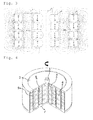
Fig. 1 is a schematic sectional view of a preferent embodiment of the superconducting magnetic bearing of the present invention. -
Fig. 2 is a schematic cross section with plotted magnetic field lines of an embodiment of the present invention with the north poles of the inner and outer sets of permanent magnets are on the same planes. -
Fig. 3 is a schematic cross section with plotted magnetic field lines of another embodiment of the present invention with the north poles of the inner set and the south poles of the outer set of permanent magnets are on the same planes. -
Fig. 4 is a schematic sectional view of another preferent embodiment of the superconducting magnetic bearing of the present invention provided with an outermost superconducting body for magnetic shielding. -
Fig. 5 graphs the axial force vs. axial displacement for a bearing according to the embodiment of present invention shown inFigs. 1 and 2 (continuous line) and for an equivalent radial gap bearing with only an inner set of permanent magnets (dashed line). -
Fig. 6 graphs the radial force vs. radial displacement for a bearing according to the embodiment of present invention shown inFigs. 1 and 2 (continuous line) and for an equivalent radial gap bearing with only an inner set of permanent magnets (dashed line). - A preferred embodiment of the superconducting magnetic bearing of the present invention, as shown in
Fig.1 , is provided with a rotor (2) firmly joined to a rotating member, typically a shaft (1). Said rotor (2) is provided with an inner set of axially magnetised ring permanent magnets (3) being their magnetisation directions opposite for contiguous permanent magnets and with symmetry under rotation of the bearing. The rotor (2) also comprises an outer set (4) of ring permanent magnets axially magnetised being their magnetisation directions opposite for contiguous permanent magnets and with symmetry under rotation, being the outer set (4) concentric with the inner set of permanent magnets (3). - The preferred embodiment in
Fig. 1 also includes a stator provided with a set of superconducting rings (6). The stator (6) is located between the inner and outer sets of permanent magnets (3, 4) in the rotor. Preferred superconducting materials are ReBaCuO and specifically, YBa2Cu3Ox. In order to contain the coolant that may be required to achieve the working temperature of the superconductor, the embodiment is provided with a housing or vessel (7) with a plurality of coolant intakes (8). - The preferred embodiment in
Fig. 1 is also provided with a set of spacers (5) between contiguous permanent magnets within a set, being mainly made of a magnetisable material as for example ferrite or steel. In a preferred embodiment particularly easy to manufacture these spacers are a plurality of steel washers. They act as flux collectors improving the characteristics of the magnetic field applied to the superconducting bodies. - In a preferred embodiment the north poles of the said permanent magnets in the inner and outer sets (3,4) are contained in the same planes as shown in
Fig. 2 . - In another embodiment of the present invention, the north poles of the said permanent magnets in the inner set (3) and the south poles in the outer set (4) are contained in the same planes as shown in
Fig. 3 . - Other embodiments of this invention can include a plurality of outer sets of permanent magnets or magnetic field generators and/or a plurality of superconducting bodies between the said sets.
- Additionally, a preferred embodiment of the present invention is also provided with an outermost and/or an innermost superconducting body.
Fig. 4 shows an embodiment with such an outermost superconducting body (9) -improving the magnetic shielding and the load capabilities. - In other embodiments of the present invention, the condition of rotor and stator can be exchanged, so that the superconducting body becomes the rotor and the sets of magnets become the stator of the bearing.
-
-
EP 0559839 (B1 ), -
EP 0728956 (B1 ) -
WO 95/32541 -
US 6831384 (B2 ) -
DE102010034258 (A1 ), -
US 7659646 (B2 ), -
US 7466051 (B2 ) -
WO 2011/048019 (A1 ) -
US2002071882 (A1 ) -
US5831361 (A ) -
JPH0681845 (A -
JPH0544728 (A
Claims (13)
- A non-contact bearing structure comprisinga) A rotor provided witha.1) An inner set of two or more permanent magnets axially magnetised with symmetry under rotation, their magnetisation direction being opposite between contiguous permanent magnets.a.2) An outer set of two or more ring permanent magnets axially magnetised with symmetry under rotation, their magnetisation direction being opposite between contiguous permanent magnets and being the outer set concentrically aligned with the said inner set of permanent magnets.b) A stator located between said inner and outer sets of permanent magnets of the rotor, provided with at least a superconducting part.
- A non-contact bearing structure comprisinga) A stator provided witha.1) An inner set of two or more permanent magnets axially magnetised with symmetry under rotation, their magnetisation direction being opposite between contiguous permanent magnets.a.2) An outer set of two or more ring permanent magnets axially magnetised with symmetry under rotation, their magnetisation direction being opposite between contiguous permanent magnets and being the outer set concentrically aligned with the said inner set of permanent magnets.b) A rotor located between said inner and outer sets of permanent magnets of the stator, provided with at least a superconducting part.
- A bearing structure according to claims 1 or 2 also comprisinga) A plurality of outer sets of two or more permanent magnets axially magnetised with symmetry under rotation, their magnetisation direction being opposite between contiguous permanent magnets and being the outer sets concentrically aligned with the said inner set of permanent magnets.b) A plurality of superconducting bodies, comprising each of them at least a superconducting part, located between two of the sets of permanent magnets.
- A bearing structure according to any of the previous claims being the magnets of the outer set or sets characterized by being their north poles on the same planes as the north poles of the corresponding magnets of the inner set.
- A bearing structure according to any of the previous claims where the permanent magnets in the said inner set are ringshaped and where at least a superconducting part is located inside the hole of the inner set of permanent magnets.
- A bearing structure according to any of the previous claims where there is at least one superconducting part surrounding, at least partially, the outermost set of permanent magnets.
- A bearing structure according to any claim from 1 to 6 where one or more magnetic field generators are used in place of at least one of the permanent magnets.
- A bearing structure according to claim 7 where at least one of the said magnetic field generators is a superconducting magnet.
- A bearing structure according to claims 7 or 8 where at least one of the said magnetic field generators is a persistent current.
- A bearing structure according to any of the claims from 7 to 9 where at least one of the said magnetic field generators is an electromagnet.
- A bearing structure according to any of the previous claims where the preferred superconducting material is ReBa2Cu3Ox/Ag where Re represents a rare-earth chemical element like Yttrium (Y), Lanthanum (La) or Samarium (Sm).
- A bearing structure according to any of the claims from 1 to 11 where there is at least one spacer mainly composed of a magnetisable material placed between two contiguous permanent magnets in a set.
- A bearing structure according to any previous claim where cooling means are provided for refrigeration of the superconductors.
Priority Applications (1)
| Application Number | Priority Date | Filing Date | Title |
|---|---|---|---|
| EP13382535.6A EP2886891A1 (en) | 2013-12-20 | 2013-12-20 | High-performance radial gap superconducting magnetic bearing |
Applications Claiming Priority (1)
| Application Number | Priority Date | Filing Date | Title |
|---|---|---|---|
| EP13382535.6A EP2886891A1 (en) | 2013-12-20 | 2013-12-20 | High-performance radial gap superconducting magnetic bearing |
Publications (1)
| Publication Number | Publication Date |
|---|---|
| EP2886891A1 true EP2886891A1 (en) | 2015-06-24 |
Family
ID=49885117
Family Applications (1)
| Application Number | Title | Priority Date | Filing Date |
|---|---|---|---|
| EP13382535.6A Withdrawn EP2886891A1 (en) | 2013-12-20 | 2013-12-20 | High-performance radial gap superconducting magnetic bearing |
Country Status (1)
| Country | Link |
|---|---|
| EP (1) | EP2886891A1 (en) |
Cited By (8)
| Publication number | Priority date | Publication date | Assignee | Title |
|---|---|---|---|---|
| CN105761871A (en) * | 2016-05-04 | 2016-07-13 | 扬州大学 | Double helical high-temperature superconducting magnet energy-storing device |
| CN109281936A (en) * | 2018-12-02 | 2019-01-29 | 迈格钠磁动力股份有限公司 | A kind of permanent-magnet suspension bearing stator |
| EP3322907A4 (en) * | 2015-07-13 | 2019-03-20 | Lawrence Livermore National Security, LLC | PASSIVE MAGNETIC BEARING ELEMENTS AND CONFIGURATIONS USING ALTERNATIVE POLARIZATION AND AMPERIC CURRENT DIRECTION |
| US11028877B2 (en) | 2017-04-01 | 2021-06-08 | Carrier Corporation | Magnetic radial bearing with flux boost |
| US11035406B2 (en) | 2017-04-01 | 2021-06-15 | Carrier Corporation | Magnetic radial bearing with flux boost |
| US11047421B2 (en) | 2017-04-01 | 2021-06-29 | Carrier Corporation | Magnetic radial bearing with flux boost |
| CN115831527A (en) * | 2022-11-21 | 2023-03-21 | 苏州八匹马超导科技有限公司 | Superconducting magnet framework ejector rod mechanism |
| CN118705274A (en) * | 2024-07-04 | 2024-09-27 | 苏州广炽能源有限公司 | Multi-ring permanent magnet axial magnetic bearing |
Citations (6)
| Publication number | Priority date | Publication date | Assignee | Title |
|---|---|---|---|---|
| JPH0544728A (en) * | 1991-08-09 | 1993-02-23 | Koyo Seiko Co Ltd | Drive device |
| US5220232A (en) * | 1991-09-03 | 1993-06-15 | Allied Signal Aerospace | Stacked magnet superconducting bearing |
| JPH05180226A (en) * | 1991-12-27 | 1993-07-20 | Koyo Seiko Co Ltd | Superconductive bearing device |
| EP0559839A1 (en) * | 1990-12-04 | 1993-09-15 | Univ Houston | SUPREME CONDUCTING MAGNETIC BEARINGS FOR HIGH TEMPERATURES. |
| JPH0886315A (en) * | 1994-09-16 | 1996-04-02 | Natl Aerospace Lab | Superconductive bearing device |
| US6831384B2 (en) * | 2000-09-26 | 2004-12-14 | Siemens Aktiengesellschaft | Magnetic bearing |
-
2013
- 2013-12-20 EP EP13382535.6A patent/EP2886891A1/en not_active Withdrawn
Patent Citations (6)
| Publication number | Priority date | Publication date | Assignee | Title |
|---|---|---|---|---|
| EP0559839A1 (en) * | 1990-12-04 | 1993-09-15 | Univ Houston | SUPREME CONDUCTING MAGNETIC BEARINGS FOR HIGH TEMPERATURES. |
| JPH0544728A (en) * | 1991-08-09 | 1993-02-23 | Koyo Seiko Co Ltd | Drive device |
| US5220232A (en) * | 1991-09-03 | 1993-06-15 | Allied Signal Aerospace | Stacked magnet superconducting bearing |
| JPH05180226A (en) * | 1991-12-27 | 1993-07-20 | Koyo Seiko Co Ltd | Superconductive bearing device |
| JPH0886315A (en) * | 1994-09-16 | 1996-04-02 | Natl Aerospace Lab | Superconductive bearing device |
| US6831384B2 (en) * | 2000-09-26 | 2004-12-14 | Siemens Aktiengesellschaft | Magnetic bearing |
Cited By (10)
| Publication number | Priority date | Publication date | Assignee | Title |
|---|---|---|---|---|
| EP3322907A4 (en) * | 2015-07-13 | 2019-03-20 | Lawrence Livermore National Security, LLC | PASSIVE MAGNETIC BEARING ELEMENTS AND CONFIGURATIONS USING ALTERNATIVE POLARIZATION AND AMPERIC CURRENT DIRECTION |
| CN105761871A (en) * | 2016-05-04 | 2016-07-13 | 扬州大学 | Double helical high-temperature superconducting magnet energy-storing device |
| US11028877B2 (en) | 2017-04-01 | 2021-06-08 | Carrier Corporation | Magnetic radial bearing with flux boost |
| US11035406B2 (en) | 2017-04-01 | 2021-06-15 | Carrier Corporation | Magnetic radial bearing with flux boost |
| US11047421B2 (en) | 2017-04-01 | 2021-06-29 | Carrier Corporation | Magnetic radial bearing with flux boost |
| CN109281936A (en) * | 2018-12-02 | 2019-01-29 | 迈格钠磁动力股份有限公司 | A kind of permanent-magnet suspension bearing stator |
| CN109281936B (en) * | 2018-12-02 | 2023-10-27 | 迈格钠磁动力股份有限公司 | Permanent magnet suspension bearing stator |
| CN115831527A (en) * | 2022-11-21 | 2023-03-21 | 苏州八匹马超导科技有限公司 | Superconducting magnet framework ejector rod mechanism |
| CN115831527B (en) * | 2022-11-21 | 2023-09-12 | 苏州八匹马超导科技有限公司 | Superconducting magnet skeleton ejector rod mechanism |
| CN118705274A (en) * | 2024-07-04 | 2024-09-27 | 苏州广炽能源有限公司 | Multi-ring permanent magnet axial magnetic bearing |
Similar Documents
| Publication | Publication Date | Title |
|---|---|---|
| EP2005562B1 (en) | Generator and magnetic flux conducting unit | |
| CN102377298B (en) | Five-degree-of-freedom (five-DOF) bearing-free permanent magnet synchronous motor | |
| US8471660B2 (en) | Assembly for magnetization of rare-earth permanent magnets | |
| Slininger et al. | An overview on passive magnetic bearings | |
| CN108869543B (en) | A kind of hybrid superconducting magnetic bearing system of flywheel energy storage | |
| US20170005560A1 (en) | Flux focusing magnetic gear assembly using ferrite magnets or the like | |
| RU2664716C1 (en) | Superconducting synchronous electric machine with the armature windings and excitation in the fixed cryostat | |
| WO2019205683A1 (en) | Three-phase and four-degree-of-freedom axial phase splitting bearingless flywheel motor | |
| RU133986U1 (en) | KINETIC ENERGY STORAGE WITH MAGNETIC HTSC SUSPENSION | |
| CN108448808A (en) | Axial split-phase permanent magnet magnetic levitation switch reluctance flywheel motor with sleeve pole shoe teeth | |
| US6369476B1 (en) | High temperature superconductor bearings | |
| AU2007271814A1 (en) | Synchronous machine having magnetic bearing excited by the rotor | |
| CN1988324B (en) | A high-speed reluctance motor | |
| JPH10136609A (en) | Motor and power storage device using it | |
| RU2540696C1 (en) | High-rate electrical machine with vertical shaft | |
| KR20240166434A (en) | Rotating machine type synchronous condenser with reduced friction | |
| RU97018U1 (en) | KINETIC ENERGY STORAGE | |
| CN110611397A (en) | flywheel energy storage device | |
| JP2016039733A (en) | Flywheel device, and power generation and drive motor device | |
| Sung et al. | 300 Wh class superconductor flywheel energy storage system with a horizontal axle | |
| CN205908642U (en) | Superconducting magnetic suspension turbine vertical bearing | |
| Sung et al. | Effect of a passive magnetic damper in a flywheel system with a hybrid superconductor bearing set | |
| RU157741U1 (en) | KNETIC ENERGY KINETIC STORAGE LEVITATION SYSTEM | |
| CN107740813A (en) | A kind of composite excitation type radial direction magnetic bearing | |
| CN201351680Y (en) | High-temperature superconducting magnetic suspension bearing for flywheel device |
Legal Events
| Date | Code | Title | Description |
|---|---|---|---|
| PUAI | Public reference made under article 153(3) epc to a published international application that has entered the european phase |
Free format text: ORIGINAL CODE: 0009012 |
|
| 17P | Request for examination filed |
Effective date: 20131220 |
|
| AK | Designated contracting states |
Kind code of ref document: A1 Designated state(s): AL AT BE BG CH CY CZ DE DK EE ES FI FR GB GR HR HU IE IS IT LI LT LU LV MC MK MT NL NO PL PT RO RS SE SI SK SM TR |
|
| AX | Request for extension of the european patent |
Extension state: BA ME |
|
| STAA | Information on the status of an ep patent application or granted ep patent |
Free format text: STATUS: THE APPLICATION IS DEEMED TO BE WITHDRAWN |
|
| 18D | Application deemed to be withdrawn |
Effective date: 20160105 |