EP2886463B1 - Aktuatormontageverfahren und herstellverfahren für eine eisschutzvorrichtung - Google Patents
Aktuatormontageverfahren und herstellverfahren für eine eisschutzvorrichtung Download PDFInfo
- Publication number
- EP2886463B1 EP2886463B1 EP14004165.8A EP14004165A EP2886463B1 EP 2886463 B1 EP2886463 B1 EP 2886463B1 EP 14004165 A EP14004165 A EP 14004165A EP 2886463 B1 EP2886463 B1 EP 2886463B1
- Authority
- EP
- European Patent Office
- Prior art keywords
- actuator
- shell structure
- ice
- profile
- actuators
- Prior art date
- Legal status (The legal status is an assumption and is not a legal conclusion. Google has not performed a legal analysis and makes no representation as to the accuracy of the status listed.)
- Active
Links
Images


Classifications
-
- B—PERFORMING OPERATIONS; TRANSPORTING
- B64—AIRCRAFT; AVIATION; COSMONAUTICS
- B64F—GROUND OR AIRCRAFT-CARRIER-DECK INSTALLATIONS SPECIALLY ADAPTED FOR USE IN CONNECTION WITH AIRCRAFT; DESIGNING, MANUFACTURING, ASSEMBLING, CLEANING, MAINTAINING OR REPAIRING AIRCRAFT, NOT OTHERWISE PROVIDED FOR; HANDLING, TRANSPORTING, TESTING OR INSPECTING AIRCRAFT COMPONENTS, NOT OTHERWISE PROVIDED FOR
- B64F5/00—Designing, manufacturing, assembling, cleaning, maintaining or repairing aircraft, not otherwise provided for; Handling, transporting, testing or inspecting aircraft components, not otherwise provided for
- B64F5/10—Manufacturing or assembling aircraft, e.g. jigs therefor
-
- B—PERFORMING OPERATIONS; TRANSPORTING
- B32—LAYERED PRODUCTS
- B32B—LAYERED PRODUCTS, i.e. PRODUCTS BUILT-UP OF STRATA OF FLAT OR NON-FLAT, e.g. CELLULAR OR HONEYCOMB, FORM
- B32B37/00—Methods or apparatus for laminating, e.g. by curing or by ultrasonic bonding
- B32B37/10—Methods or apparatus for laminating, e.g. by curing or by ultrasonic bonding characterised by the pressing technique, e.g. using action of vacuum or fluid pressure
-
- B—PERFORMING OPERATIONS; TRANSPORTING
- B32—LAYERED PRODUCTS
- B32B—LAYERED PRODUCTS, i.e. PRODUCTS BUILT-UP OF STRATA OF FLAT OR NON-FLAT, e.g. CELLULAR OR HONEYCOMB, FORM
- B32B37/00—Methods or apparatus for laminating, e.g. by curing or by ultrasonic bonding
- B32B37/12—Methods or apparatus for laminating, e.g. by curing or by ultrasonic bonding characterised by using adhesives
- B32B37/1284—Application of adhesive
-
- B—PERFORMING OPERATIONS; TRANSPORTING
- B32—LAYERED PRODUCTS
- B32B—LAYERED PRODUCTS, i.e. PRODUCTS BUILT-UP OF STRATA OF FLAT OR NON-FLAT, e.g. CELLULAR OR HONEYCOMB, FORM
- B32B37/00—Methods or apparatus for laminating, e.g. by curing or by ultrasonic bonding
- B32B37/14—Methods or apparatus for laminating, e.g. by curing or by ultrasonic bonding characterised by the properties of the layers
- B32B37/16—Methods or apparatus for laminating, e.g. by curing or by ultrasonic bonding characterised by the properties of the layers with all layers existing as coherent layers before laminating
-
- B—PERFORMING OPERATIONS; TRANSPORTING
- B32—LAYERED PRODUCTS
- B32B—LAYERED PRODUCTS, i.e. PRODUCTS BUILT-UP OF STRATA OF FLAT OR NON-FLAT, e.g. CELLULAR OR HONEYCOMB, FORM
- B32B38/00—Ancillary operations in connection with laminating processes
-
- B—PERFORMING OPERATIONS; TRANSPORTING
- B64—AIRCRAFT; AVIATION; COSMONAUTICS
- B64D—EQUIPMENT FOR FITTING IN OR TO AIRCRAFT; FLIGHT SUITS; PARACHUTES; ARRANGEMENT OR MOUNTING OF POWER PLANTS OR PROPULSION TRANSMISSIONS IN AIRCRAFT
- B64D15/00—De-icing or preventing icing on exterior surfaces of aircraft
- B64D15/12—De-icing or preventing icing on exterior surfaces of aircraft by electric heating
-
- B—PERFORMING OPERATIONS; TRANSPORTING
- B64—AIRCRAFT; AVIATION; COSMONAUTICS
- B64D—EQUIPMENT FOR FITTING IN OR TO AIRCRAFT; FLIGHT SUITS; PARACHUTES; ARRANGEMENT OR MOUNTING OF POWER PLANTS OR PROPULSION TRANSMISSIONS IN AIRCRAFT
- B64D15/00—De-icing or preventing icing on exterior surfaces of aircraft
- B64D15/16—De-icing or preventing icing on exterior surfaces of aircraft by mechanical means, e.g. pulsating mats or shoes attached to, or built into, surface
- B64D15/163—De-icing or preventing icing on exterior surfaces of aircraft by mechanical means, e.g. pulsating mats or shoes attached to, or built into, surface using electro-impulsive devices
-
- H—ELECTRICITY
- H10—SEMICONDUCTOR DEVICES; ELECTRIC SOLID-STATE DEVICES NOT OTHERWISE PROVIDED FOR
- H10N—ELECTRIC SOLID-STATE DEVICES NOT OTHERWISE PROVIDED FOR
- H10N30/00—Piezoelectric or electrostrictive devices
- H10N30/01—Manufacture or treatment
- H10N30/07—Forming of piezoelectric or electrostrictive parts or bodies on an electrical element or another base
- H10N30/072—Forming of piezoelectric or electrostrictive parts or bodies on an electrical element or another base by laminating or bonding of piezoelectric or electrostrictive bodies
- H10N30/073—Forming of piezoelectric or electrostrictive parts or bodies on an electrical element or another base by laminating or bonding of piezoelectric or electrostrictive bodies by fusion of metals or by adhesives
-
- B—PERFORMING OPERATIONS; TRANSPORTING
- B32—LAYERED PRODUCTS
- B32B—LAYERED PRODUCTS, i.e. PRODUCTS BUILT-UP OF STRATA OF FLAT OR NON-FLAT, e.g. CELLULAR OR HONEYCOMB, FORM
- B32B38/00—Ancillary operations in connection with laminating processes
- B32B2038/0052—Other operations not otherwise provided for
- B32B2038/0076—Curing, vulcanising, cross-linking
-
- B—PERFORMING OPERATIONS; TRANSPORTING
- B32—LAYERED PRODUCTS
- B32B—LAYERED PRODUCTS, i.e. PRODUCTS BUILT-UP OF STRATA OF FLAT OR NON-FLAT, e.g. CELLULAR OR HONEYCOMB, FORM
- B32B2307/00—Properties of the layers or laminate
- B32B2307/20—Properties of the layers or laminate having particular electrical or magnetic properties, e.g. piezoelectric
- B32B2307/206—Insulating
-
- B—PERFORMING OPERATIONS; TRANSPORTING
- B32—LAYERED PRODUCTS
- B32B—LAYERED PRODUCTS, i.e. PRODUCTS BUILT-UP OF STRATA OF FLAT OR NON-FLAT, e.g. CELLULAR OR HONEYCOMB, FORM
- B32B2605/00—Vehicles
- B32B2605/18—Aircraft
-
- Y—GENERAL TAGGING OF NEW TECHNOLOGICAL DEVELOPMENTS; GENERAL TAGGING OF CROSS-SECTIONAL TECHNOLOGIES SPANNING OVER SEVERAL SECTIONS OF THE IPC; TECHNICAL SUBJECTS COVERED BY FORMER USPC CROSS-REFERENCE ART COLLECTIONS [XRACs] AND DIGESTS
- Y10—TECHNICAL SUBJECTS COVERED BY FORMER USPC
- Y10T—TECHNICAL SUBJECTS COVERED BY FORMER US CLASSIFICATION
- Y10T156/00—Adhesive bonding and miscellaneous chemical manufacture
- Y10T156/10—Methods of surface bonding and/or assembly therefor
-
- Y—GENERAL TAGGING OF NEW TECHNOLOGICAL DEVELOPMENTS; GENERAL TAGGING OF CROSS-SECTIONAL TECHNOLOGIES SPANNING OVER SEVERAL SECTIONS OF THE IPC; TECHNICAL SUBJECTS COVERED BY FORMER USPC CROSS-REFERENCE ART COLLECTIONS [XRACs] AND DIGESTS
- Y10—TECHNICAL SUBJECTS COVERED BY FORMER USPC
- Y10T—TECHNICAL SUBJECTS COVERED BY FORMER US CLASSIFICATION
- Y10T29/00—Metal working
- Y10T29/49—Method of mechanical manufacture
- Y10T29/49826—Assembling or joining
Definitions
- the invention relates to an actuator assembly method for assembling at least one actuator.
- the invention relates to an actuator assembly method for producing a mechanical anti-ice device for an aircraft for preventing ice formation on a surface area and/or de-icing the surface area of the aircraft.
- the invention also relates to an assembly device for use in such a method and a manufacturing method for producing a hybrid device for de-icing and/or preventing ice formation for an aircraft.
- the invention lies in the technical field of assembling actuators.
- the invention is explained by way of example using the production and/or assembly of a device for de-icing and/or preventing ice formation for an aircraft, but is not limited to this area.
- Ice forms on exposed areas of aircraft such as leading edges of wings, tail surfaces, horizontal stabilizers or even engine inlets when the aircraft, such as an airplane, flies through a cloud containing supercooled water droplets or drops/moisture impact a supercooled aircraft structure. As a layer of ice grows, it affects airflow over the affected surface. If the layer becomes large enough, it can cause, for example, carrying problems or handling problems for the aircraft.
- Ice protection systems are already in use on aircraft to prevent such ice formation. Most ice protection systems are designed as anti-ice systems to prevent ice formation. For this are in the Typically structure-integrated heating systems are provided. During flight in icing conditions, wing edges become e.g. B. heated with hot branch air or compressor bleed air (so-called bleed air) or by electric heaters in the wing edges. In addition, pneumatically operated de-icing devices are used, especially in smaller aircraft, which inflate rubber mats or rubber hoses integrated on the leading edge of the wing at regular intervals, thereby removing accumulated ice.
- Known systems or devices for removing ice accumulations in flight on aerodynamically efficient surfaces can generally be divided into pneumatic, thermal and mechanical de-icing systems. That's how it is in the EP 0 658 478 B1 a device for pneumatic de-icing of surfaces on aircraft is known. From the US 6,702,233 B1 a device for de-icing or preventing ice formation on surface areas of aircraft using warm branch air from the engine is known. From the US2013/032671 A1 a device for preventing ice formation using piezoelectric actuators is known.
- thermal defrosting using electrical heating elements.
- An example of such a thermal de-icing system is in the EP 1 017 580 B1 described.
- WO 2007/071231 A1 For example, three-dimensional piezo actuators are known that can generate complex deformation states on different basic structures.
- Basic structures can be large concave mirrors from telescopes or aerodynamic profiles.
- the piezo actuators can be used to investigate the flow properties of the aerodynamic profiles.
- the invention is based on the object of improving the assembly of actuators.
- step c4) contains: c4.1) material connection of the actuator to the inside.
- step c4) contains: c4.2) Gluing the actuator to the inside.
- step c4) contains: c4.2.1) Applying an adhesive to the inside and/or a surface of the actuator to be bonded to the inside before attaching the actuator to the inside.
- step c4) contains: c4.2.2) Hardening of the adhesive while pressing the actuator on the inside.
- step c4.2.2) contains: Curing the adhesive under temperature to create a mechanical preload due to the different coefficients of thermal expansion of the actuator material and the shell structure.
- step c4) contains: c4.3)Intermediate layer of electrical insulation between the actuator and the inside.
- step c2) contains: c2.1) Holding the actuator on the stamp, for example using double-sided adhesive tape, during insertion into the shell structure and/or attachment to the shell structure.
- a temporary, detachable connection of the actuator to the stamp can be established, for example by electrostatic attraction or by sucking the actuator onto the stamp.
- step c3) contains: c3.1) guided movement of the stamp by a guide device.
- step c3) contains: c3.2)Maintaining and/or keeping constant a pressing pressure by means of an energy storage device, such as at least one disc spring.
- step c3) contains: c3.3) Supporting the outside of the shell structure by means of a support form that is complementary to the outside.
- step a) contains: Providing the shell structure with at least one flat inner surface on the inside of the shell structure.
- an actuator can also be used which has the same curvature as the shell structure.
- step c) contains: Attaching the at least one actuator to the at least one flat inner surface.
- step b) contains: b.1) Providing at least one piezoelectric actuator.
- the invention provides a manufacturing method for producing a hybrid de-icing device for an aircraft, for thermally and mechanically de-icing a surface area and/or for keeping the surface area free thermally and mechanically, comprising: Carrying out an actuator assembly method according to one of the previously described embodiments for the purpose of producing and/or assembling the mechanical ice protection device and through the step: d) attaching a heat emission device for heating at least part of the shell structure.
- step d) contains: d1) Providing a heat emission device (12) which is designed for linear heat emission in order to produce a predetermined breaking point or predetermined breaking line (32) or dividing line in ice accumulating on the surface area.
- step d) contains: d2) Attaching the heat release device (12) to the inside of the shell structure in the area of a front edge and/or a stagnation line of an aerodynamic profile body to be formed by the shell structure.
- the at least one piezoelectric actuator to be assembled is designed as a d 33 stack actuator or multilayer actuator.
- the actuator is preferably mounted in such a way that the direction of expansion of the at least one actuator, in particular of the at least one piezoelectric actuator, is aligned in the span direction when used on a profile of a wing.
- the direction of expansion is aligned with at least one directional component parallel to the surface to be deformed, preferably with a directional component transverse to the direction of flow, such as the direction of flight. If the connection between the actuator and the shell structure is sufficiently strong, a change in the expansion of the actuators will cause a corresponding change Bracing of the shell structure so that a deformation such as a dent or bulge can be achieved.
- Areas of application of the methods and devices of the invention preferably relate to the assembly and production of devices for de-icing and/or preventing ice formation.
- the invention relates to the assembly of actuators for deforming or moving surface areas in order to remove ice or prevent the formation of ice using mechanical energy.
- the invention creates a manufacturing method for producing a mechanical ice protection device for an aircraft for de-icing a surface area of the aircraft by carrying out an actuator assembly method previously described, wherein the shell structure has on its outside the surface area to be kept free of ice and / or to be de-iced.
- the device to be produced with this is designed as a hybrid device for de-icing and/or preventing ice formation using thermal and mechanical energy.
- a device for de-icing and/or preventing ice formation can be created for an aircraft, with a heat release device for releasing heat to a surface area of the aircraft, the heat release device for linear heat release for the purpose of producing a predetermined breaking point or predetermined breaking line in ice accumulating on the surface area is trained.
- a preferred embodiment of the device for de-icing and/or preventing ice formation comprises a deformation device for deforming at least part of the surface of the surface area.
- the deformation device has at least one piezoelectric actuator or an arrangement of piezoelectric actuators for deforming a surface of the surface region.
- Such actuators are preferably mounted on a shell structure of an aerodynamic profile body using the assembly method according to the invention.
- a heat emission device which is preferably to be provided in addition to the mechanical ice protection device, is designed to emit heat in a line shape in order to create a predetermined breaking point or predetermined breaking line of ice accumulating on the surface area.
- the heat release device is thus designed to release heat along a heat release line. Depending on the energy used, ice on it weakens along the heat release line so that the ice can be broken up, or no ice forms along the heat release line at all, so that at most ice forms on sections of the surface area separated by the heat release line can train.
- the deformation device has a first deformation unit on a first section of the surface area and a second deformation unit on a second surface area separated from the first section by the heat release line.
- the deformation device comprises a first deformation unit on a first side of a heat release line of the heat release device, for deforming a first section of the surface area located on the first side, and a second deformation unit on the second side of the heat release line for deforming a second section located on the second side of the surface area.
- the device to be assembled further comprises a surface coating for the surface area that reduces ice adhesion forces.
- the heat emission device has at least one heating wire and/or at least one piezoelectric actuator, which is designed and set up in such a way that it is capable of linear heat emission.
- the actuator mounting method is not limited to use in de-icing and/or anti-icing devices, but may generally be used to mount an actuator in a cup-shaped body.
- FIG. 1 and 2 represent only exemplary embodiments. Many other different configurations of the device 10 are possible.
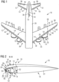
- Fig. 1 shows an aircraft 16 in the form of an aircraft 20.
- the aircraft 20 each has wings 22 formed by profile bodies 18, tail fins 24 and engine inlets 25.
- the surface area 14 on which ice can accumulate during flight is the surface area 14 on which ice can accumulate during flight.
- the aircraft 16 has a device 10 for de-icing and/or preventing ice formation on the surface area 14.
- the device 10 has a heat release device 12 for releasing heat to the surface area 14.
- the heat emission device 12 is preferably not designed for large-area heat emission, but rather for linear heat emission along a heat release line 28. Through a linear release along the heat release line 28, ice 30 accumulating on the surface area 14 can be weakened in a line and separated along the heat release line 28.
- the heat release device 12 is designed to form a predetermined breaking point or a predetermined breaking line 32 for the ice 30.
- the heat release device 12 is designed such that the heat is released in a line along the outermost front edge 26 and in particular along the stagnation line 34 of the respective aerodynamic profile 36 of the respective profile body 18.
- the stagnation line 34 is the line that connects the stagnation points of the aerodynamic profile 36 with one another, or in other words the line on an aerodynamic profile 36 at which, with a corresponding air flow - in 3 and 4 represented by the arrow and the velocity vector v - is divided into flows to the two sides or upwards and downwards. The highest pressure builds up during flight along stagnation line 34.
- the heat release device 12 is designed such that the heat is released along the current stagnation line 34 of the respective aerodynamic profile 36 of the respective profile body 18. This can be achieved, for example, by several heating wires attached in a line in the area on the leading edge of the wing. This means that even under flight conditions with different angles of the wing surfaces or the wing profile, it can be ensured that the ice at or close to the respective stagnation line is split up by the linear heat input.
- the device 10 further has ice protection devices 37 for removing ice and / or for preventing ice accumulation in or on the sections 38, 39 of the surface area 14 divided by the heat release line 28 or stagnation line 34.
- a deformation device 40 for deforming corresponding parts or sections 38, 39 of the surface area 14 is provided as an example of an ice protection device 37.
- a surface coating 42 is additionally provided on the surface area 14 to reduce ice adhesion forces.
- the device 10 is designed as a hybrid de-icing system 44, which removes ice or prevents ice formation using at least two principles.
- the heat emission device 12 is preferably formed by an electro-thermal system 46, which is designed as a subsystem of the hybrid de-icing system 44.
- the heat emission device 12 has a heating wire 48 for the defined formation of a predetermined breaking point on the stagnation line 34 of the profile 36.
- the electro-thermal heating wire 48 is moved along the stagnation line 34 of the Profile 36 installed.
- the heating wire 48 is embedded in a matrix of fastening material, such as in particular an epoxy resin matrix 50.
- the heating wire 48 can also be attached to the inside of the profile 36 using a thin foil adhesive.
- a single-core sheathed heating conductor with a slim, circular cross section is used as the preferred heating wire 48.
- a carbon fiber cord can also be used as a heating element. For example, it is soaked with epoxy resin and/or wrapped with layers of glass for electrical insulation.
- the heat emission device 12 can also use a piezo actuator, which is controlled at high frequency, for example, and thus emits both thermal and mechanical energy.
- a piezo actuator of the further embodiment not shown here without heating wire 48 should be designed in such a way that it emits the heat along the heat emission line 28 in such a way that a predetermined breaking point is formed.
- the device 10 shown here also has an electro-mechanical de-icing system 52 as a further subsystem of the hybrid de-icing system 44.
- the electro-mechanical de-icing system 52 can be viewed as an example of the deformation device 40.
- the electro-mechanical de-icing system 52 preferably has at least one piezo actuator 54.
- the deformation device 40 and its electro-mechanical de-icing system 52 have a first deformation unit 56 and a second deformation unit 57.
- the first deformation unit 56 serves to deform a first section 38 of the surface area 14 on a first side of the heat release line 28.
- the first section 38 is, for example, the section of the surface area 14 enclosing the front edge 26, which lies above the stagnation line 34.
- the second section 39 would be deformed by the second deformation unit 57 is, in the example shown, the section of the leading edge surface area 14 located below the stagnation line 34.
- the electro-mechanical de-icing system 52 preferably has at least two piezo actuators 54, 55, namely at least a first piezo actuator 54 for the first deformation unit 56 and at least one second piezo actuator 55 for the second deformation unit 57.
- the first and second sections 38, 39 can in particular be formed by a first and a second longitudinal half of the profile body 18.
- the installation of at least two piezo actuators 54, 55 in the area of a front edge 26 of an aerodynamic profile 36, such as the profile body 18 of a wing 22, is provided.
- the piezo actuators 54, 55 lie in the direction of flow behind the linear heat release area defined by the heating wire 48 - heat release line 28. They are therefore used to remove ice accumulations behind the stagnation point of the profile 36 and to remove ice deposits from returning and solidifying drops through the electro-thermal system 46.
- dss actuators for example with a length of approximately 30 mm, a width of approximately 10 mm and a height of approximately 2 mm, can be used as piezo actuators 54, 55.
- the structure of the piezo actuators is expressly referred to WO 2007/071231 A1 referred.
- flat surfaces 82 must be provided for the preferred, cuboid piezo actuators 54, 55 for application on the inside 76 of the profile 36 (e.g. the wing profile 74).
- the preferred, cuboid piezo actuators are particularly advantageous because they are available as inexpensive standard components.
- shape-adapted piezo actuators can also be used, which have the same curved contour as the profile 36 in order to ensure the most efficient possible mechanical coupling into the structure.
- the device 10 for de-icing and/or preventing ice formation in the preferred embodiment as a hybrid de-icing system 44 preferably also has a device for reducing ice adhesion to the surface area 14.
- This device can be viewed as another de-icing subsystem. In particular, this device has the surface coating 42.
- the surface area 14 around the front edge 26 of the aerodynamic profile 36 or, for example, an entire surface area of the profile body 18 - for example the wing 22 - is coated in such a way that the surface has minimal adhesion properties between ice (or water) and the profile surface.
- a NACA-0012 aluminum wing profile with a nanostructured, superhydrophobic surface coating 42 in the area of the leading edge 26 is provided as the profile body 18.
- Fig. 2 therefore shows the preferred embodiment of the device 10 with the heat emission device 12 provided with the heating wire 48 along the stagnation line 34 as an electro-thermal system 46, with the first and second deformation units 56, 57 formed with piezo actuators 54, 55 for deforming a first section and a Second section 38, 39 of the surface area 14 formed deformation device 40 as an electro-mechanical de-icing system 52 and with the surface coating 42 as a further subsystem of the hybrid de-icing system 44.
- Fig. 3 shows the basic sketch of the aerodynamic profile 36 using the example of the profile of the wing 22 with a front edge 26 completely covered by ice 30.
- the indicated heating wire 48 which is glued to the inside of the profile 36 at the level of the stagnation line 34, did not become one in this example Time electro-thermally heated. Even if a bond in the boundary layer between ice and the surface in the surface area 14 of the profile 36 is broken by controlling the indicated piezoelectric actuators 54, 55, the ice layer surrounding the front edge 26 of the profile 36 still remains in the same place because the aerodynamic forces the flow - represented by the velocity vector v - continues to press the ice layer against the front edge 26 of the profile 36.
- FIG. 4 a schematic sketch of the profile 36 of the profile body 18, for example forming the wing 22, with - for example permanently - operated heating wire 48, which is glued to the inside of the profile 36 at the level of the stagnation line 34.
- the point in point in a two-dimensional view or in a three-dimensional view, linear introduction of thermal energy generates a predetermined breaking point or a predetermined breaking line 32, which serves the purpose of partitioning or splitting the accumulation of ice 30 at the stagnation line 34 of the profile 36 of the wing 22 into an upper portion 60 and a lower portion 61 of the ice layer serves. More generally, the ice 30 is divided into a first portion 60 and a second portion 61 along the predetermined breaking line 32. As a result, both ice portions 60, 61 can be removed by the indicated piezoelectric actuators 54, 55.
- thermal energy is transmitted to the profile 36 in a line in the span direction. More generally, heat is emitted from a heat emission device 12 in a linear manner when viewed in three dimensions or in points when viewed in two dimensions, as in Fig. 4 shown.
- the piezo actuators 54, 55 are able to deform the surface of the profile 36 of the wing 22 and thus break the bond in the interface between ice and surface.
- the ice 30 released from the surface continues to be pressed against the profile 36 of the wing 22 due to the aerodynamic dynamic pressure of the flow.
- the surface area 14 is not finally freed from ice accumulation - see Fig. 3 .
- the heating wire 48 - in contrast to electro-thermal systems or heat emission devices that work with heating mats - is not used for the large-scale thermal removal of ice accumulations on the aerodynamic profile 36, such as the wing 22, but for the linear break-up of the ice layer.
- a de-icing method that can be carried out, for example, with the device 10 for de-icing a surface area 14 of an aircraft 16 and/or for avoiding ice formation on the surface area 14 of the aircraft 16 has the step of introducing heat along a line on the surface area 14 in order to form a predetermined breaking line 32 in ice 30 accumulating on the surface area 14 or to form a dividing line in ice accumulating on the surface area or in water droplet accumulations accumulating on the surface area.
- ice can be removed by breaking up ice along a predetermined breaking line.
- the introduction of heat is carried out along a heat release line 28 to form a predetermined breaking line 32 or dividing line along a stagnation line 34 of an aerodynamic profile 36.
- the de-icing method further comprises at least one of the steps of deforming the surface area 14 to break up ice along the breaking line 32 and/or to remove ice broken up along the breaking line 32 or water accumulation accumulating on the sides of the breaking line and/or providing a surface area 14 with a surface quality that reduces ice adhesion forces - in particular by means of a corresponding surface coating 42.
- the heating wire 48 of the electro-thermal system 46 is operated in permanent running-wet anti-icing mode.
- the heating wire can also alternatively be operated in cyclic de-icing mode in order to enable the removal of the separated portions 60, 61 of ice 30 on the profile 36 by means of the deforming device 40.
- the deformation of the surface area 14 is preferably carried out by piezo actuators 54, 55.
- the deformation of the surface of the profile 36 takes place by controlling the piezo actuators 54, 55 in the range of the resonance frequency of the structure - here a low control voltage is preferably used with a contact voltage of 0 V - or by a quasi-static excitation of the piezo actuators - here a high amplitude with a contact voltage >0 V is preferably used - whereby the ice accumulations in the area in the flow direction behind the stagnation line 34 of the profile 36 are removed.
- Another possible control lies in a continuous, dynamic control of the piezoelectric actuators 54, 55 with a square-wave signal with a defined edge steepness at a repetition frequency of, for example, 1 Hz.
- the wing structure is caused to resonate via the square-wave signal; this effect further affects the static deflection has a positive effect on the chipping off of the ice 30.
- the direction of movement of the piezo actuators 54, 55 can be in the span direction or flight direction (d 33 effect) or flat (d 31 effect).
- the ice-phobic properties of a super-hydrophobic coating 42 increase the adhesive bonding forces between ice 30 and the surface of profile 36 reduced to a minimum. This enables energy-efficient removal of all ice accumulations on the profile 36.
- a profile 36 of the wing 22 was iced under real flight conditions in an icing wind tunnel on a laboratory scale.
- all three subsystems of the hybrid de-icing system 44 all ice bag accumulations adhering to the wing profile were removed.
- the three subsystems were used simultaneously.
- a comparison of the energy requirements of the hybrid de-icing system 44 with a de-icing system that has already been certified for flight operations - in particular a purely electro-thermal de-icing system - showed very significant energy savings.
- the heat output device 12 could have a plurality of heating wires 48 to ensure the redundancy of a hybrid de-icing system 44.
- a heating wire 48 could be provided directly on the stagnation line 34 and further heating wires (not shown in detail) are arranged in the area around the stagnation line 34.
- piezo actuators 54, 55 can also be used on the respective sections 38, 39.
- Such devices 10 are suitable for carrying out particularly energy-efficient processes for de-icing or preventing ice formation.
- an electro-mechanical de-icing system 52 is advantageous for this purpose, which enables deformation of a surface area of the profile body 18 that is as close as possible to the front edge.
- a mounting device 70 and an actuator mounting method for mounting actuators 54, 55 are explained in more detail, which allows such an attachment.
- the mounting device 70 and the actuator mounting method are explained based on the embodiment of a hybrid device 10 for illustration purposes, the applicability is not limited thereto. In particular, they can be used wherever deformation of a highly curved shell structure 72 or one enclosing a narrow space is to take place using actuators.
- a NACA-0012 wing profile is used, which was milled from solid.
- Fig. 5 shows the shell structure 72 of the profile 36 of the profile body 18. It is, for example, a profile 36 milled from solid for a wing 22 in the form of a symmetrical, slim NACA 0012 profile.
- the assembly method can also be applied to any other profile 36 of the possible profile bodies 18 of the aircraft.
- a flat surface 82 is formed for later bonding of the preferably cuboid piezoelectric multilayer actuators.
- the surface on the inside 76 of the profile 36, where the piezo actuators 54, 55 will later be glued, should have a suitable roughness value and be cleaned before further use. Furthermore, a (preferably) flat surface 82 must be provided in this area.
- the actuator 54, 55 can also alternatively be glued to a curved shell structure 72.
- the shell structure 72 and the actuator 54, 55 preferably have the same curvature.
- a mounting device 70 is then used to mount the actuators 54, 55, as shown, for example, in a schematic demonstration structure in Fig. 6 shown and in the Fig. 7 to 10 is indicated.
- the assembly device 70 has a stamp 86, a pressing device 88, holding means 90 and a support mold 92.
- the stamp 86 is used to hold and press the actuators 54, 55 onto the inside 76 of the shell structure 72.
- the stamp 86 has a receiving area 84, the surface shape of which is designed to be complementary to the part of the surface structure of the inside 76 to which the actuators 54, 55 are to be attached. If, for example, the flat surfaces 82 are provided, the receiving area 84 is formed with flat surfaces inclined at corresponding angles. For this purpose, the stamp 86 can, for example, be designed to be trapezoidal overall.
- the holding means 90 are designed to temporarily hold the actuators 54, 55 on the stamp 86.
- the pressing device 88 is used to press the stamp 86 onto the inside 76.
- a guide device 94 and a pressure force generating device 95 are provided for the guided movement of the stamp 86 and pressing.
- a force storage element such as a plate spring 97, is in particular provided.
- the support mold 92 serves to support the thin shell structure 72 during pressing.
- the surface of the support mold 92 is designed to be complementary to the surface area 14 of the shell structure 72.
- Fig. 6 shows a demonstration structure of a mounting device 70 for mounting actuators on a small-scale profile 36 for wind tunnel tests. Shown are the profile 36, side guide rails 96 for forming the guide device 94, the stamp 86 with piezo actuators attached to it 54, 55, a polyamide mold 98 as an example for the support mold 92 and nuts 100 for assembly.
- the pressure force generating device 95 has threaded rods 112. Using screwdrivers (not shown), the nuts 100 on the threaded rods 112 can be turned towards the inside 76 in order to press the stamp 86 against the inside 76.
- the disc springs 97 are provided as force storage elements for maintaining the constant pressure. Washers 99 can also be provided, which are arranged between the nut 100 and the disc spring 97.
- the step of applying the actuators 54, 55 to the stamp 86 is first carried out.
- An exemplary embodiment of this step of application or attachment of the actuators to the stamp 86 is explained in more detail below.
- An adhesive 102 for bonding the actuators to the inside is applied to the actuators.
- a thin layer of a film adhesive 104 is cut and applied to the side of the piezo actuator 54, 55, which is later to be connected to the profile 36.
- an insulation layer 106 made of an electrically insulating material is provided between the inside and the actuators 54, 55.
- a prepreg glass fiber fabric 108 for example, is provided for electrical insulation from the support structure to form the insulation layer 106.
- the required insulation distance is set by the number of prepreg layers. The higher the electrical control voltage is selected, the greater the insulation distance is selected.
- a piezo actuator 54, 55 with the holding means 90 which has, for example, an adhering medium, such as a double-sided adhesive tape 110 for temporary bonding for later resolvability after the bonding process, is placed on both sides. or is designed to adhere using a physical principle (e.g. suction via vacuum or electrostatic charge), applied or adhered.
- a physical principle e.g. suction via vacuum or electrostatic charge
- a double-sided adhesive tape 110 has proven to be particularly suitable as a holding means 90.
- the piezo actuators 54, 55 can be aligned via markings on the stamp 86, via stops on the stamp or another additional alignment device (all not shown).
- the step of materially connecting, in particular gluing, the actuators 54, 55 to the shell structure 72 can take place, which will be explained in more detail below.
- the stamp 86 is guided, for example with guide rails 96 and threaded rods 112.
- the stamp 86 can either be on both sides, on one side or, in the case of open profiles, from be guided at the rear.
- the contact pressure should be kept constant throughout the gluing step while the adhesive 102 is curing. This can be achieved, for example, by means of force storage elements such as disc springs (not shown).
- the contact pressure is counteracted with a negative form - support form 92 - of the profile 36 (e.g. made of polyamide) in order to maintain the shape of the profile 36.
- a curing device For curing the adhesive 102, a curing device is provided, which is designed to carry out the curing step to be carried out for the respective adhesive 102.
- the curing process of the adhesive 102 occurs in an oven (not shown) at a suitable temperature, preferably below the Curie temperature (120 ° C). To maintain the temperature, it can be checked, for example, with a control hole near the positioning point of the piezo actuator on the stamp 86.
- a mechanical prestress By curing at a suitable temperature, a mechanical prestress can be introduced as required or desired.
- the mechanical preload protects the actuator better from tensile stress and/or from defects, which can occur particularly in resonance operation.
- the heating wire 48 can also be glued to the inside 76 of the profile 36 in the area of the stagnation line 34 using the same principle.
- the contact pressure is released and the stamp 86 can be removed.
- a simplified removal of the stamp 86 in the warm state proves to be particularly suitable, since only a small amount of force is required to release the adhesive tape 110 from the piezo actuators 54, 55.
- Fig. 7 shows schematically the components used in the application process of the actuators to the shell structure.
- Fig. 8 shows schematically the step of applying the actuators 54, 55 to the stamp and the insertion of the stamp 86 into the profile 36.
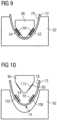
- Fig. 9 shows schematically the step of pressing the stamp 86.
- Fig. 10 shows schematically the step of removing the stamp 86.
- the method can also be used to assemble actuators for other purposes. Examples of this are in the WO 2007/071231 A1 shown, to which express reference is made for further details of other possible uses.
Landscapes
- Engineering & Computer Science (AREA)
- Manufacturing & Machinery (AREA)
- Aviation & Aerospace Engineering (AREA)
- Mechanical Engineering (AREA)
- Transportation (AREA)
- Physics & Mathematics (AREA)
- Fluid Mechanics (AREA)
- Control Of Resistance Heating (AREA)
- Body Structure For Vehicles (AREA)
- Aerodynamic Tests, Hydrodynamic Tests, Wind Tunnels, And Water Tanks (AREA)
- General Electrical Machinery Utilizing Piezoelectricity, Electrostriction Or Magnetostriction (AREA)
Description
- Die Erfindung betrifft ein Aktuatormontageverfahren zum Montieren wenigstens eines Aktuators. Insbesondere betrifft die Erfindung ein Aktuatormontageverfahren zur Herstellung einer mechanischen Eisschutzeinrichtung für ein Luftfahrzeug zum Vermeiden einer Eisbildung an einem Oberflächenbereich und/oder Enteisen des Oberflächenbereichs des Luftfahrzeuges. Außerdem betrifft die Erfindung eine Montagevorrichtung zur Verwendung in einem solchen Verfahren und ein Herstellverfahren zur Herstellung einer hybriden Vorrichtung zur Enteisung und/oder zur Vemeidung von Eisbildung für ein Luftfahrzeug.
- Die Erfindung liegt auf dem technischen Gebiet der Montage von Aktuatoren. Die Erfindung wird beispielhaft anhand der Herstellung und/oder Montage einer Vorrichtung zur Enteisung und/oder Vermeidung von Eisbildung für ein Luftfahrzeug erläutert, ist aber nicht auf dieses Gebiet beschränkt.
- Eis bildet sich an exponierten Stellen von Luftfahrzeugen wie Vorderkanten von Flügeln, Leitwerken, horizontalen Stabilisatoren oder auch Triebwerkseinläufen, wenn das Luftfahrzeug, wie beispielsweise ein Flugzeug, durch eine Wolke fliegt, die unterkühlte Wassertröpfchen enthält oder Tropfen/Feuchtigkeit auf eine unterkühlte Luftfahrzeugstruktur treffen. Wenn eine Eisschicht wächst, beeinträchtigt sie die Luftströmung über der betroffenen Oberfläche. Wenn die Schicht groß genug wird, können z.B. Tragprobleme oder Handhabungsprobleme für das Luftfahrzeug entstehen.
- Es sind bereits Eisschutzsysteme bei Luftfahrzeugen im Einsatz, um eine solche Eisbildung zu vermeiden. Die meisten Eisschutzsysteme sind als Anti-Eissysteme zum Vermeiden einer Eisbildung ausgebildet. Hierzu sind in der Regel Struktur-integrierte Heizsysteme vorgesehen. Während des Fluges unter Vereisungsbedingungen werden Flügelkanten z. B. mit heißer Abzweigluft oder Verdichterzapfluft (sog. bleed air) oder durch elektrische Heizungen in den Flügelkanten beheizt. Zudem sind, vor allem in kleineren Flugzeugen, pneumatisch betriebene Enteisungsvorrichtungen im Einsatz, welche an der Flügelvorderkante integrierte Gummimatten bzw. Gummischläuche in regelmäßigen Abständen aufblasen, wodurch ein Ablösen von angelagertem Eis erzielt wird.
- Dabei sind die herkömmlichen Enteisungsmaßnahmen mit einem hohen energetischen Aufwand während des Fluges verbunden. An energetischem Aufwand für das Freimachen von Oberflächen des Luftfahrzeuges von Eis fallen etwa 240 bis 260 kW an Abzweigluftleistung oder ca. 130 bis 150 kW elektrischer Heizleistung für eine zu enteisende Fläche von ca. 12 bis 15 m2 an. Diese Daten entsprechen im Falle von Abzweigluft Flächenleistungen von ca. 18,5 kW/m2 bzw. etwa 10 kW/m2 bei elektrischer Heizung.
- Bekannte Systeme oder Vorrichtungen zur Entfernung von Eisakkumulationen im Flug auf aerodynamisch effizienten Oberflächen lassen sich generell unterteilen in pneumatische, thermische und mechanische Enteisungssysteme. So ist in der
EP 0 658 478 B1 eine Vorrichtung zur pneumatischen Enteisung von Oberflächen an Luftfahrzeugen bekannt. Aus derUS 6 702 233 B1 ist eine Vorrichtung zur Enteisung beziehungsweise Vermeidung von Eisbildung an Oberflächenbereichen von Luftfahrzeugen unter Verwendung von warmer Abzweigluft aus dem Triebwerk bekannt. Aus derUS2013/032671 A1 ist eine Vorrichtung zur Vermeidung von Eisbildung unter Verwendung von piezoelektrischen Aktuatoren bekannt. - Aus der
DE 10 2010 045 450 B4 ist eine Anordnung zur Enteisung eines Oberflächenbereichs eines Luftfahrzeuges durch Bestrahlung des Oberflächenbereichs mit einem Laser bekannt. - Andere Vorrichtungen zur Enteisung und/oder Vermeidung von Eisbildung verwenden eine thermische Enteisung unter Verwendung von elektrischen Heizelementen. Insbesondere ist es bekannt, basierend auf der großflächigen Wärmezufuhr durch eine elektrothermische Heizmatte das Vereisen der Oberfläche eines Flügelprofils zu verhindern. Ein Beispiel für ein derartiges thermisches Enteisungssystem ist in der
EP 1 017 580 B1 beschrieben. - Weiter sind auch Vorrichtungen zur Enteisung und/oder Vermeidung von Eisbildung bekannt, die als hybride Vorrichtungen mehrere Möglichkeiten zur Enteisung, wie insbesondere den Einsatz thermischer Energie und mechanischer Verformungen nutzen. Beispiele von bekannten hybriden Enteisungssystemen sind aus den folgenden Literaturstellen bekannt:
- G. Fortin, M. Adomou, J. Perron, "Experimental Study of Hybrid Anti-Icing Systems Combining Thermoelectric and Hydrophobic Coatings", SAE International, Warrendale, Pa, 2011: Diese Publikation beschäftigt sich mit einem elektro-thermischen Anti-Eis-System in Kombination mit Eis abweisenden Oberflächenbeschichtungen zur Reduktion des Energiebedarfs bei der Enteisung. Die Wärmezufuhr erfolgt bei diesem System großflächig, um die gesamte, von Eisaufwuchs betroffene Oberfläche zu schützen. Der Nachteil des Systems ist somit die Tatsache, dass durch den permanenten Betrieb des großflächig anzubringenden Anti-Eis-Systems im Bereich der gesamten Flügelvorderkante ein grundsätzlich hoher Energieverbrauch auftritt.
- K. Al-Khalil, T. Ferguson, D. Phillips, "A Hybrid Anti-icing Ice Protection System", AIAA 97-0302 (1997): Diese Publikation befasst sich mit einem hybriden Enteisungssystem der Firma Cox & Company, Inc. welches sich aus einem thermischen "Running-wet"-Anti-Eis-Subsystem sowie einem Subsystem auf Basis von elektro-expulsiven Aktuatoren (EMEDS) zusammensetzt. Das thermische Subsystem bedeckt den Bereich des Tropfenaufschlags an der Flügelvorderkante in großflächiger Weise entweder teilweise oder auch vollständig. Somit lässt sich für das thermische Subsystem der Nachteil anführen, dass ein relativ großer Flächenanteil des Flügelvorderkantenbereichs beheizt werden muss, um die Wassertropfen weiter stromabwärts zu transportieren. Dort können die zu einer Eisakkumulation erstarrten Tropfen dann mittels der EMEDS-Aktuatoren periodisch entfernt werden. Ein weiterer Nachteil des bekannten hybriden Systems ist zudem die Größe der EMEDS-Aktuatoren.
- Aus der
WO 2007/071231 A1 sind beispielsweise dreidimensionale Piezoakutatoren bekannt, die komplexe Verformungszustände an unterschiedlichen Basisstrukturen erzeugen können. Basisstrukturen können etwa große Hohlspiegel von Teleskopen oder aerodynamische Profile sein. Insbesondere können die Piezoaktuatoren zur Untersuchung von Strömungseigenschaften der aerodynamischen Profile verwendet werden. - Der Erfindung liegt die Aufgabe zugrunde, die Montage von Aktuatoren zu verbessern.
- Diese Aufgabe wird durch ein Aktuatormontageverfahren nach Anspruch 1 gelöst. Eine vorteilhafte Verwendung des Aktuatormontageverfahrens bei der Herstellung einer mechanischen Vorrichtung zur Enteisung und/oder Vermeidung von Eisbildung und bei der Herstellung einer hybriden Vorrichtung zur Enteisung und/oder Vermeidung von Eisbildung sind Gegenstand der Nebenansprüche.
- Vorteilhafte Ausgestaltungen der Erfindung sind Gegenstand der Unteransprüche.
- Die Erfindung schafft ein Aktuatormontageverfahren zum Montieren wenigstens eines Aktuators in einer stark gekrümmten oder einen engen Raum einschließenden Schalenstruktur eines Profils eines Profilkörpers eines Luftfahrzeuges, umfassend die Schritte:
- a) Bereitstellen einer Schalenstruktur,
- b) Bereitstellen wenigstens eines Aktuators, der zur Verformung des Oberflächenbereichs der Schalenstruktur geeignet ist durch Bereitstellen wenigstens eines ersten Aktuators zur Verformung eines auf einer ersten Längshälfte der Schalenstruktur ausgebildeten Abschnitts des Oberflächenbereichs und Bereitstellen wenigstens eines zweiten Aktuators zur Verformung eines auf einer zweiten Längshälfte der Schalenstruktur ausgebildeten Abschnitts des Oberflächenbereichs, und
- c) Befestigen des wenigstens einen Aktuators an einer Innenseite der Schalenstruktur durch gleichzeitiges Befestigen des wenigstens einen ersten Aktuators an der Innenseite der ersten Längshälfte und des wenigstens einen zweiten Aktuators an der Innenseite der zweiten Längshälfte,
- c1) Anordnen des wenigstens einen Aktuators an einem Stempel zum flächigen Anpressen des wenigstens einen Aktuators an der Innenseite der Schalenstrukur,
- c2) Anhaften des Aktuators an den Stempel mittels eines lösbaren Haltemittels,
- c3) Anpressen des Aktuators an die Innenseite der Schalenstruktur innerhalb des Profils mittels des Stempels,
- c4) Verbinden des Aktuators mit der Innenseite,
- c5) Lösen und/oder Entfernen des Stempels.
- Es ist bevorzugt, dass Schritt c4) enthält:
c4.1) stoffschlüssiges Verbinden des Aktuators mit der Innenseite. - Es ist bevorzugt, dass Schritt c4) enthält:
c4.2)Verkleben des Aktuators mit der Innenseite. - Es ist bevorzugt, dass Schritt c4) enthält:
c4.2.1) Auftragen eines Klebemittels auf die Innenseite und/oder eine mit der Innenseite zu verklebende Fläche des Aktuators vor dem Anbringen des Aktuators an die Innenseite. - Es ist bevorzugt, dass Schritt c4) enthält:
c4.2.2) Aushärten des Klebemittels unter Anpressen des Aktuators an die Innenseite. - Es ist bevorzugt, dass Schritt c4.2.2) enthält:
Das Aushärten des Klebemittels unter Temperaturbeaufschlagung zum Erzeugen einer mechanischen Vorspannung aufgrund der unterschiedlichen Wärmeausdehnungskoeffizienten des Aktuatormaterials und der Schalenstruktur. - Es ist bevorzugt, dass Schritt c4) enthält:
c4.3)Zwischenlage einer elektrischen Isolationsschicht zwischen Aktuator und Innenseite. - Es ist bevorzugt, dass Schritt c2) enthält:
c2.1) Halten des Aktuators an dem Stempel beispielsweise mittels zweiseitigen Klebebands während des Einbringens in die Schalenstrukur und/oder des Anbringens an die Schalenstruktur. Alternativ oder zusätzlich kann eine temporäre, lösbare Verbindung des Aktuators mit dem Stempel, etwa durch elektrostatische Anziehung oder durch Ansaugen des Aktuators an den Stempel hergestellt werden. - Es ist bevorzugt, dass Schritt c3) enthält:
c3.1) geführtes Bewegen des Stempels durch eine Führungseinrichtung. - Es ist bevorzugt, dass Schritt c3) enthält:
c3.2)Aufrechterhalten und/oder Konstanthalten eines Pressdrucks mittels eines Kraftspeichers, wie z.B. wenigstens einer Tellerfeder. - Es ist bevorzugt, dass Schritt c3) enthält:
c3.3)Abstützen der Außenseite der Schalenstruktur mittels einer zu der Außenseite komplementären Stützform. - Es ist bevorzugt, dass Schritt a) enthält:
Bereitstellen der Schalenstrukur mit wenigstens einer ebenen Innenfläche auf der Innenseite der Schalenstrukur. Alternativ oder zusätzlich kann auch ein Aktuator verwendet werden, welcher die gleiche Krümmung wie die Schalenstruktur aufweist. - Es ist bevorzugt, dass Schritt c) enthält:
Befestigen des wenigstens einen Aktuators an der wenigstens einen ebenen Innenfläche. - Es ist bevorzugt, dass Schritt b) enthält:
b.1) Bereitstellen wenigstens eines piezoelektrischen Aktuators. - Gemäß einem weiteren Aspekt schafft die Erfindung ein Herstellverfahren zum Herstellen einer hybriden Enteisungsvorrichtung für ein Luftfahrzeug, zum thermischen und mechanischen Enteisen eines Oberflächenbereichs und/oder zum thermischen und mechanischen Freihalten des Oberflächenbereichs, umfassend:
Durchführen eines Aktuatormontageverfahren gemäß einer der zuvor beschriebenen Ausgestaltungen zwecks Herstellen und/oder Montage der mechanischen Eisschutzeinrichtung und durch den Schritt:
d) Anbringen einer Wärmeabgabeeinrichtung zum Erwärmen zumindest eines Teils der Schalenstruktur. - Es ist bevorzugt, dass Schritt d) enthält:
d1) Bereitstellen einer Wärmeabgabeeinrichtung (12), die zur linienförmigen Wärmeabgabe zwecks Erzeugung einer Sollbruchstelle oder Sollbruchlinie (32) oder Trennlinie in sich auf dem Oberflächenbereich ansammelndem Eis ausgebildet ist. - Es ist bevorzugt, dass Schritt d) enthält:
d2) Anbringen der Wärmeabgabeeinrichtung (12) an der Innenseite der Schalenstruktur im Bereich einer Vorderkante und/oder einer Stagnationslinie eines durch die Schalenstruktur zu bildenden aerodynamischen Profilkörpers. - Es ist bevorzugt, dass der zu montierende wenigstens eine piezoelektrische Aktuator als d33-Stapelaktuator oder Multilayeraktuator ausgebildet ist.
- Vorzugsweise erfolgt die Montage des Aktuators derart, dass die Ausdehungsrichtung des wenigstens einen Aktuators, insbesondere des wenigstens einen piezoelektrischen Aktuators bei Verwendung an einem Profil eines Flügels in Spannweitenrichtung ausgerichtet ist. Insbesondere ist die Ausdehnungsrichtung mit zumindest einer Richtungskomponente in parallel zu der zu verformenden Oberfläche ausgerichtet, vorzugsweise mit einer Richtungskomponente quer zur Anströmungsrichtung wie z.B. der Flugrichtung. Bei entsprechend fester Verbindung von Aktuator und Schalenstruktur bewirkt dann eine Änderung der Ausdehnung der Aktuatoren eine entsprechende Verspannung der Schalenstruktur, so dass eine Verformung wie z.B. eine Einbeulung oder Ausbeulung erzielbar ist.
- Anwendungsgebiete der Verfahren und Vorrichtungen der Erfindung betreffen bevorzugt die Montage und die Herstellung von Vorrichtungen zur Enteisung und/oder Vermeidung von Eisbildung. Insbesondere betrifft die Erfindung die Montage von Aktuatoren zur Verformung oder Bewegung von Oberflächenbereichen, um so mittels mechanischer Energie Eis zu entfernen oder die Entstehung von Eis zu vermeiden.
- Gemäß einem weiteren Aspekt schafft die Erfindung ein Herstellverfahren zur Herstellung einer mechanischen Eisschutzeinrichtung für ein Luftfahrzeug zum Enteisen eines Oberflächenbereichs des Luftfahrzeuges mittels Durchführen eines Aktuatormontageverfahrens zuvor beschriebenen Aktuatormontageverfahrens, wobei die Schalenstruktur den an deren Außenseite der von Eis freizuhaltenden und/oder zu enteisenden Oberflächenbereich aufweist.
- Es ist bevorzugt, dass die damit herzustellende Vorrichtung als hybride Vorrichtung zur Enteisung und/oder Vermeidung von Eisbildung mittels thermischer und mechanischer Energie ausgebildet ist.
- Vorzugsweise lässt sich eine Vorrichtung zur Enteisung und/oder Vermeidung von Eisbildung für ein Luftfahrzeug schaffen, mit einer Wärmeabgabeeinrichtung zur Abgabe von Wärme an einen Oberflächenbereich des Luftfahrzeuges, wobei die Wärmeabgabeeinrichtung zur linienförmigen Wärmeabgabe zwecks Erzeugung einer Sollbruchstelle oder Sollbruchlinie in sich auf dem Oberflächenbereich ansammelndem Eis ausgebildet ist.
- Eine bevorzugte Ausgestaltung der Vorrichtung zur Enteisung und/oder Vermeidung von Eisbildung umfasst eine Verformungseinrichtung zur Verformung zumindest eines Teils der Oberfläche des Oberflächenbereichs.
- Es ist bevorzugt, dass die Verformungseinrichtung wenigstens einen piezoelektrischen Aktuator oder eine Anordnung von piezoelektrischen Aktuatoren zur Verformung einer Oberfläche des Oberflächenbereichs aufweist.
- Vorzugsweise werden derartige Aktuatoren mit dem Montageverfahren gemäß der Erfindung an einer Schalenstruktur eines aerodynamischen Profilkörpers montiert.
- Eine vorzugsweise zusätzlich zu der mechanischen Eisschutzeinrichtung vorzusehende Wärmeabgabeeinrichtung ist zur Wärmeabgabe in Linienform ausgebildet, um so eine Sollbruchstelle oder Sollbruchlinie von sich auf dem Oberflächenbereich ansammelndem Eis zu erzeugen. Die Wärmeabgabeeinrichtung ist somit zur Wärmeabgabe entlang einer Wärmeabgabelinie ausgebildet. Je nach Energieeinsatz bildet sich entlang der Wärmeabgabelinie eine Schwächung von darauf befindlichem Eis aus, so dass das Eis aufgebrochen werden kann, oder es bildet sich entlang der Wärmeabgabelinie erst gar kein Eis aus, so dass sich allenfalls Eis an durch die Wärmeabgabelinie getrennten Abschnitten des Oberflächenbereichs ausbilden kann.
- Bei einer besonders bevorzugten Ausgestaltung der mit den Montageverfahren gemäß der Erfindung oder deren vorteilhaften Ausgestaltungen zu montierenden Vorrichtung weist die Verformungseinrichtung eine erste Verformungseinheit auf einem ersten Abschnitt des Oberflächenbereichs und eine zweite Verformungseinheit auf einer durch die Wärmeabgabelinie von dem ersten Abschnitt getrennten zweiten Oberflächenbereich auf.
- Bevorzugt umfasst die Verformungseinrichtung eine erste Verformungseinheit auf einer ersten Seite von einer Wärmeabgabelinie der Wärmeabgabeeinrichtung, zur Verformung eines auf der ersten Seite befindlichen ersten Abschnitts des Oberflächenbereichs und eine zweite Verformungseinheit auf der zweiten Seite von der Wärmeabgabelinie zur Verformung eines auf der zweiten Seite befindlichen zweiten Abschnitts des Oberflächenbereichs.
- In einer besonders bevorzugten Ausgestaltung umfasst die zu montierende Vorrichtung weiter eine Eisadhäsionskräfte herabsetzende Oberflächenbeschichtung für den Oberflächenbereich.
- Es ist bevorzugt, dass die Wärmeabgabeeinrichtung wenigstens einen Heizdraht und/oder wenigstens einen piezoelektrischen Aktuator, der derart ausgebildet und eingerichtet ist, dass er zur linienförmigen Wärmeabgabe fähig ist, aufweist.
- Ausführungsbeispiele der Erfindung werden nachfolgend anhand der beigefügten Zeichnungen näher erläutert. Darin zeigt:
- Fig. 1
- eine schematische, teilweise weggeschnittene Darstellung eines Luftfahrzeuges am Beispiel eines Flugzeuges, wobei die Vorderkanten von aerodynamischen Profilkörpern des Luftfahrzeuges, wie insbesondere Tragflügel, Flossen des Leitwerks und Triebwerkseinläufe mit einer Vorrichtung zur Enteisung und/oder Vermeidung von Eisbildung versehen sind;
- Fig. 2
- eine schematische, teils perspektivische, teils geschnittene Darstellung durch einen aerodynamischen Profilkörper, beispielsweise zum Bilden eines Tragflügels des Luftfahrzeugs von
Fig. 1 , gezeigt im Schnitt entlang der Linie II-II vonFig. 1 , wobei der Profilkörper mit der Vorrichtung zur Enteisung und/oder Vermeidung von Eisbildung versehen ist; - Fig. 3
- in schematischer geschnittener Darstellung einen Schnitt durch die Vorderkante des Profilkörpers von
Fig. 2 mit der Vorrichtung zur Enteisung und/oder Vermeidung von Eisbildung ohne Betrieb einer Wärmeabgabeeinrichtung; - Fig. 4
- eine Darstellung wie in
Fig. 3 bei Betrieb der Wärmeabgabeeinrichtung; - Fig. 5
- eine schematische Darstellung einer Schalenstruktur zum Bilden des Profilkörpers, an den Aktuatoren zum Bilden einer mechanischen Eisschutzeinrichtung der Vorrichtung zu montieren sind;
- Fig. 6
- eine Prinzipdarstellung einer Montagevorrichtung zur Durchführung einer Montage von Aktuatoren an der Schalenstruktur von
Fig. 5 ; und - Fig. 7 bis 10
- in schematischer Darstellung Längsschnitte durch die Montagevorrichtung mit der Schalenstruktur zur Verdeutlichung unterschiedlicher Schritte eines Montageverfahrens.
- Im Folgenden werden Ausführungsbeispiele eines Aktuatormontageverfahrens sowie eines unter Verwendung dieses Aktuatormontageverfahrens durchführbaren Herstellverfahrens zur Herstellung einer Vorrichtung 10 zur Enteisung und/oder Vermeidung von Eisbildung näher erläutert.
- Das Aktuatormontageverfahren ist nicht auf die Verwendung bei Vorrichtungen zur Enteisung und/oder Vermeidung von Eisbildung beschränkt, sondern kann allgemein zum Montieren eines Aktuators in einem schalenförmigen Körper verwendet werden.
- Hierzu werden zunächst anhand der
Figuren 1 bis 4 Ausführungsbeispiele einer unter Verwendung dieser Verfahren erhältlichen Vorrichtung 10 zur Enteisung und/oder Vermeidung von Eisbildung an einem Oberflächenbereich 14 eines Luftfahrzeuges 16 sowie deren Funktion näher erläutert, bevor auf die einzelnen Schritte der Montage anhand der verbleibenden Figuren näher eingegangen wird. - Die Darstellungen in den
Fig. 1 und 2 stellen lediglich Ausführungsbeispiele dar. Viele andere abweichende Ausgestaltungen der Vorrichtung 10 sind möglich. -
Fig. 1 zeigt ein Luftfahrzeug 16 in Form eines Flugzeuges 20. Das Flugzeug 20 weist jeweils durch Profilkörper 18 gebildete Flügel 22, Leitwerksflossen 24 und Triebwerkseinläufe 25 auf. Im Bereich um die Vorderkanten 26 der Profilkörper 18 der Flügel 22 sowie der Leitwerksflossen 24 und Triebwerkseinläufe 25 befindet sich der Oberflächenbereich 14, an dem sich im Flug Eis ansammeln kann. - Um dem entgegenzuwirken, weist das Luftfahrzeug 16 eine Vorrichtung 10 zur Enteisung und/oder Vermeidung von Eisbildung an dem Oberflächenbereich 14 auf. Die Vorrichtung 10 weist eine Wärmeabgabeeinrichtung 12 zur Abgabe von Wärme an den Oberflächenbereich 14 auf.
- Die Wärmeabgabeeinrichtung 12 ist vorzugsweise nicht zur großflächigen Wärmeabgabe ausgebildet, sondern zur linienförmigen Wärmeabgabe entlang einer Wärmeabgabelinie 28. Durch eine linienförmige Abgabe entlang der Wärmeabgabelinie 28 lässt sich an dem Oberflächenbereich 14 ansammelndes Eis 30 linienförmig schwächen und entlang der Wärmeabgabelinie 28 trennen. Insofern ist die Wärmeabgabeeinrichtung 12 zum Ausbilden einer Sollbruchstelle beziehungsweise einer Sollbruchlinie 32 für das Eis 30 ausgebildet.
- In bevorzugter Ausgestaltung ist die Wärmeabgabeeinrichtung 12 derart ausgebildet, dass die Wärme entlang der äußersten Vorderkante 26 und insbesondere entlang der Stagnationslinie 34 des jeweiligen aerodynamischen Profils 36 des jeweiligen Profilkörpers 18 linienförmig abgegeben wird. Die Stagnationslinie 34 ist die Linie, die die Staupunkte des aerodynamischen Profils 36 miteinander verbindet, oder mit anderen Worten diejenige Linie an einem aerodynamischen Profil 36, an der bei entsprechender Luftanströmung - in
Fig. 3 und 4 dargestellt durch den Pfeil und den Geschwindigkeitsvektor v - in Strömungen zu den beiden Seiten beziehungsweise nach oben und nach unten hin aufgeteilt wird. Entlang der Stagnationslinie 34 baut sich im Flug der höchste Druck auf. - Bei einer weiter bevorzugten Ausgestaltung ist die Wärmeabgabeeinrichtung 12 derart ausgebildet, dass die Wärme entlang der momentanen Stagnationslinie 34 des jeweiligen aerodynamischen Profils 36 des jeweiligen Profilkörpers 18 abgegeben wird. Dies kann beispielsweise durch mehrere, linienförmig im Bereich an der Flügelvorderkante angebrachte Heizdrähte realisiert werden. Somit kann auch unter Flugbedingungen mit verschiedener Anstellung der Flügeltragflächen bzw. des Flügelprofils gewährleistet werden, dass das Eis an bzw. nahe an der jeweiligen Stagnationslinie durch den linienförmigen Wärmeeintrag aufgespalten wird.
- Die Vorrichtung 10 weist weiter Eisschutzeinrichtungen 37 zur Entfernung von Eis und/oder zur Vermeidung einer Eisansammlung in oder an den durch die Wärmeabgabelinie 28 beziehungsweise Stagnationslinie 34 geteilten Abschnitten 38, 39 des Oberflächenbereich 14 auf.
- Bei der dargestellten Ausgestaltung ist als Beispiel für eine Eisschutzeinrichtung 37 eine Verformungseinrichtung 40 zur Verformung von entsprechenden Teilen oder Abschnitten 38, 39 des Oberflächenbereichs 14 vorgesehen.
- Weitere Maßnahmen können vorgesehen sein. Z.B. ist bei der dargestellten Ausgestaltung an dem Oberflächenbereich 14 zusätzlich eine Oberflächenbeschichtung 42 zur Verminderung von Eisadhäsionskräften vorgesehen.
- Die Vorrichtung 10 ist gemäß einer bevorzugten Ausgestaltung als hybrides Enteisungssystem 44 ausgebildet, das eine Eisentfernung oder Vermeidung von Eisbildung unter Einsatz von wenigstens zwei Prinzipien durchführt.
- Die Wärmeabgabeeinrichtung 12 ist vorzugsweise durch ein elektro-thermisches System 46 ausgebildet, das als Subsystem des hybriden Enteisungssystems 44 ausgebildet ist.
- Die Wärmeabgabeeinrichtung 12 weist in einer bevorzugten Ausgestaltung einen Heizdraht 48 zur definierten Bildung einer Sollbruchstelle an der Stagnationslinie 34 des Profils 36 auf.
- Wie insbesondere aus
Fig. 2 ersichtlich, wird hierzu zum Aufbauen der Vorrichtung 10 im Bereich der Vorderkante 26 des Profilkörpers 18, der beispielsweise zum Bilden des Flügels 22 oder zum Bilden von Leitwerksflossen 24 oder zum Bilden eines Triebwerkseinlaufs 25 dient, der elektro-thermische Heizdraht 48 entlang der Stagnationslinie 34 des Profils 36 eingebaut. In bevorzugter Ausgestaltung wird der Heizdraht 48 in eine Matrix aus Befestigungsmaterial, wie insbesondere eine Epoxidharzmatrix 50, eingebettet. - Anstelle der Verwendung einer Einbettungsmatrix kann der Heizdraht 48 auch mit einem dünnen Folienkleber an der Innenseite des Profils 36 befestigt werden. Als bevorzugter Heizdraht 48 wird ein einadriger Mantelheizleiter mit schlankem, kreisrunden Querschnitt verwendet. Alternativ kann auch eine Kohlefaserkordel als Heizelement verwendet werden. Z.B. wird diese mit Epoxidharz getränkt und/oder zur elektrischen Isolierung mit Glaslagen umwickelt.
- Anstelle des Heizdrahtes 48 kann die Wärmeabgabeeinrichtung 12 jedoch auch einen Piezoaktuator nutzen, der beispielsweise hochfrequent angesteuert wird und somit sowohl thermische als auch mechanische Energie abgibt. Ein solcher Piezoaktuator der hier nicht näher dargestellten weiteren Ausgestaltung ohne Heizdraht 48 sollte so ausgebildet sein, dass er die Wärme entlang der Wärmeabgabelinie 28 derart abgibt, dass eine Sollbruchstelle ausgebildet wird.
- Die hier dargestellte Vorrichtung 10 weist neben der Wärmeabgabeeinrichtung 12 auch ein elektro-mechanisches Enteisungssystem 52 als weiteres Subsystem des hybriden Enteisungssystems 44 auf. Das elektro-mechanische Enteisungssystem 52 kann als ein Beispiel für die Verformungseinrichtung 40 angesehen werden. Vorzugsweise weist das elektro-mechanische Enteisungssystem 52 wenigstens einen Piezoaktuator 54 auf.
- Besonders bevorzugt weist die Verformungseinrichtung 40 und deren elektro-mechanisches Enteisungssystem 52 eine erste Verformungseinheit 56 und eine zweite Verformungseinheit 57 auf. Die erste Verformungseinheit 56 dient zur Verformung eines ersten Abschnitts 38 des Oberflächenbereichs 14 auf einer ersten Seite der Wärmeabgabelinie 28. Bei dem in
Fig. 2 dargestellten Beispiel, wo der Profilkörper 18 ein Teil des Flügels 22 ist, ist der erste Abschnitt 38 beispielsweise der oberhalb der Stagnationslinie 34 liegende Abschnitt des die Vorderkante 26 einschließenden Oberflächenbereichs 14. Dementsprechend wäre der zweite Abschnitt 39, der durch die zweite Verformungseinheit 57 zu verformen ist, in dem dargestellten Beispiel der unterhalb der Stagnationslinie 34 gelegene Abschnitt des Vorderkanten-Oberflächenbereichs 14. - Dementsprechend weist das elektro-mechanische Enteisungssystem 52 vorzugsweise wenigstens zwei Piezoaktuatoren 54, 55 auf, nämlich wenigstens einen ersten Piezoaktuator 54 für die erste Verformungseinheit 56 und wenigstens einen zweiten Piezoaktuator 55 für die zweite Verformungseinheit 57. Der erste und der zweite Abschnitt 38, 39 können insbesondere durch eine erste und eine zweite Längshälfte des Profilkörpers 18 gebildet sein.
- Dementsprechend ist zum Beispiel zum Aufbau eines elektro-mechanischen Enteisungssystems 52 der Einbau von wenigstens zwei Piezoaktuatoren 54, 55 im Bereich einer Vorderkante 26 eines aerodynamischen Profils 36, wie beispielsweise dem Profilkörper 18 eines Flügels 22, vorgesehen. Die Piezoaktuatoren 54, 55 liegen in Strömungsrichtung hinter dem durch den Heizdraht 48 definierten linienförmigen Wärmeabgabebereich - Wärmeabgabelinie 28. Sie dienen damit zur Entfernung von Eisakkumulationen hinter dem Staupunkt des Profils 36 und zur Entfernung von Eisanlagerungen aus zurücklaufenden und erstarrenden Tropfen durch das elektro-thermische System 46.
- Als Piezoaktuatoren 54, 55 können insbesondere dss-Aktuatoren, beispielsweise mit einer Länge von ca. 30 mm, einer Breite von ca. 10 mm und einer Höhe von ca. 2 mm eingesetzt werden. Für nähere Einzelheiten in Bezug auf den Aufbau der Piezoaktuatoren wird ausdrücklich auf die
WO 2007/071231 A1 verwiesen. - Um eine möglichst effiziente mechanische Einkopplung in die Struktur zu ermöglichen, sind für die bevorzugten, quaderförmigen Piezoaktuatoren 54, 55 ebene Flächen 82 zur Applikation auf der Innenseite 76 des Profils 36 (z.B. des Flügelprofils 74) vorzusehen. Die bevorzugten, quaderförmigen Piezoaktuatoren sind insbesondere vorteilhaft, da sie als kostengünstige Standardbauteile erhältlich sind. Alternativ können auch formangepasste Piezoaktuatoren verwendet werden, welche die gleiche gekrümmte Kontur wie das Profil 36 vorweisen, um für eine möglichst effiziente mechanische Einkopplung in die Stuktur zu sorgen.
- Die Vorrichtung 10 zur Enteisung und/oder Vermeidung von Eisbildung weist in der bevorzugten Ausgestaltung als hybrides Enteisungssystem 44 vorzugsweise auch eine Einrichtung zur Verminderung der Eisadhäsion an dem Oberflächenbereich 14 auf. Diese Einrichtung kann als weiteres Subsystem zur Enteisung angesehen werden. Insbesondere weist diese Einrichtung die Oberflächenbeschichtung 42 auf.
- In bevorzugter Ausgestaltung wird der Oberflächenbereich 14 um die Vorderkante 26 des aerodynamischen Profils 36 oder zum Beispiel ein gesamter Oberflächenbereich des Profilkörpers 18 - beispielsweise der Flügel 22 - derart beschichtet, dass die Oberfläche minimale Adhäsionseigenschaften zwischen Eis (oder Wasser) und Profiloberfläche aufweist. Beispielsweise ist als Profilkörper 18 ein NACA-0012-Aluminium-Flügelprofil mit einer nanostrukturierten, superhydrophoben Oberflächenbeschichtung 42 im Bereich der Vorderkante 26 (z.B. Hydrobead) vorgesehen.
-
Fig. 2 zeigt demnach die bevorzugte Ausgestaltung der Vorrichtung 10 mit der mit dem Heizdraht 48 entlang der Stagnationslinie 34 versehenen Wärmeabgabeeinrichtung 12 als elektro-thermischem System 46, mit der mit Piezoaktuatoren 54, 55 gebildeten ersten und zweiten Verformungseinheit 56, 57 zum Verformen eines ersten Abschnitts und eines zweiten Abschnitts 38, 39 des Oberflächenbereichs 14 gebildeten Verformungseinrichtung 40 als elektro-mechanischem Enteisungssystem 52 und mit der Oberflächenbeschichtung 42 als weiterem Subsystem des hybriden Enteisungssystems 44. - Im Folgenden wird eine Funktionsweise eines derartigen hybriden Enteisungssystems 44 anhand der Darstellungen in den
Fig. 3 und 4 näher erläutert. -
Fig. 3 zeigt die Prinzipskizze des aerodynamischen Profils 36 am Beispiel des Profils des Flügels 22 mit einer vollständig durch Eis 30 bedeckten Vorderkante 26. Der angedeutete Heizdraht 48, welcher auf der Innenseite des Profils 36 auf Höhe der Stagnationslinie 34 aufgeklebt ist, wurde bei diesem Beispiel zu keiner Zeit elektro-thermisch beheizt. Selbst wenn nun durch Ansteuerung der angedeuteten piezoelektrischen Aktuatoren 54, 55 eine Bindung in der Grenzschicht zwischen Eis und der Oberfläche im Oberflächenbereich 14 des Profils 36 aufgebrochen wird, verbleibt die die Vorderkante 26 des Profils 36 umschließende Eisschicht dennoch an gleicher Stelle, da die aerodynamischen Kräfte der Strömung - dargestellt durch den Geschwindigkeitsvektor v - die Eisschicht weiterhin an die Vorderkante 26 des Profils 36 anpressen. - Dagegen zeigt die
Fig. 4 eine Prinzipskizze des Profils 36 des beispielsweise den Flügel 22 bildenden Profilkörpers 18 mit - z.B. permanent - betriebenem Heizdraht 48, welcher auf der Innenseite des Profils 36 auf Höhe der Stagnationslinie 34 aufgeklebt ist. Das in zweidimensionaler Betrachtung punktuelle beziehungsweise in dreidimensionaler Betrachtung linienförmige Einbringen thermischer Energie generiert eine Sollbruchstelle beziehungsweise eine Sollbruchlinie 32, welche dem Zweck der Partitionierung beziehungsweise Aufspaltung der Akkumulation von Eis 30 an der Stagnationslinie 34 des Profils 36 des Flügels 22 in einen oberen Anteil 60 und einen unteren Anteil 61 der Eisschicht dient. Allgemeiner gesehen wird das Eis 30 entlang der Sollbruchlinie 32 in einen ersten Anteil 60 und einen zweiten Anteil 61 aufgeteilt. Dadurch können beide Eisanteile 60, 61 durch die angedeuteten piezoelektrischen Aktuatoren 54, 55 entfernt werden. - Die anhand den
Fig. 3 und 4 ersichtliche Funktionsweise des hybriden Enteisungssystems 44 wird hiernach noch in näheren Einzelheiten am Beispiel einer möglichen Ausgestaltung eines - beispielsweise mit der Vorrichtung 10 durchführbaren - Verfahrens zur Enteisung oder zur Vermeidung von Eisbildung an Luftfahrzeugen näher erläutert. - Durch die Verwendung zum Beispiel eines Heizdrahtes 48 an der Stagnationslinie 34 des Profils 36 eines Flügels 22 oder dergleichen, welcher Heizdraht 48 auf die Innenseite des Profils 36 aufgeklebt ist, wird thermische Energie in Spannweitenrichtung linienförmig an das Profil 36 übertragen. Allgemeiner erfolgt eine Wärmeabgabe einer Wärmeabgabeeinrichtung 12 bei dreidimensionaler Betrachtung linienförmig beziehungsweise punktuell bei zweidimensionaler Betrachtung wie in
Fig. 4 dargestellt. Dies bedingt ein Aufschneiden der die Vorderkante 26 umschließenden Schicht Eis 30 und kann als bewusstes Einbringen einer Sollbruchstelle oder Sollbruchlinie 32 angesehen werden, welche dem Zweck der Partitionierung der Eisakkumulation in eine erste und eine zweite Eishälfte - zum Beispiel in eine obere Eishälfte und eine untere Eishälfte - dient. - Von besonderem Vorteil ist die gemeinsame Verwendung eines Heizdrahtes 48 zum Bilden des hybriden Enteisungssystems 44 in Kombination mit einer Verformung eines Oberflächenbereichs 14 des Profils 36 durch piezoelektrische Aktuatoren 54, 55.
- Verzichtet man auf den Einsatz des Heizdrahtes 48, sind die Piezoaktuatoren 54, 55 zwar in der Lage, die Oberfläche des Profils 36 des Flügels 22 zu verformen und somit die Bindung in der Grenzfläche von Eis und Oberfläche aufzubrechen. Das von der Oberfläche gelöste Eis 30 wird jedoch aufgrund des aerodynamischen Staudrucks der Anströmung weiterhin an das Profil 36 des Flügels 22 angepresst. Somit wird der Oberflächenbereich 14 nicht final von Eisakkumulation befreit - siehe
Fig. 3 . durch die Partitionierung in mehrere Abschnitte oder Anteile 60, 61, zum Beispiel eine obere und eine untere Eishälfte, mit der Wärmeabgabeeinrichtung 12, beispielsweise mittels des Heizdrahtes 48, wird ein mögliches Problem eines Anpressens des Eises 30 an das Profil 36 umgangen - siehe hierzuFig. 4 - und man kann sich zusätzlich den Effekt der aerodynamischen Anströmung des Profils 36 und der dadurch auf das Eis 30 wirkenden Kräfte zunutze machen. - Somit dient der Heizdraht 48 - im Gegensatz zu elektro-thermischen Systemen oder Wärmeabgabeeinrichtungen, die mit Heizmatten arbeiten - nicht zur großflächigen thermischen Entfernung von Eisakkumulationen auf dem aerodynamischen Profil 36, wie beispielsweise des Flügels 22, sondern zum linienförmigen Aufbrechen der Eisschicht.
- Dementsprechend weist ein zum Beispiel mit der Vorrichtung 10 durchführbares Enteisungsverfahren zur Enteisung eines Oberflächenbereichs 14 eines Luftfahrzeuges 16 und/oder zum Vermeiden von Eisbildung an dem Oberflächenbereich 14 des Luftfahrzeuges 16 den Schritt Einbringung von Wärme entlang einer Linie an dem Oberflächenbereich 14 auf, um eine Sollbruchlinie 32 in sich an dem Oberflächenbereich 14 ansammelndem Eis 30 oder eine Trennlinie in sich an dem Oberflächenbereich ansammelnden Eis oder in sich an dem Oberflächenbereich akkumulierenden Wassertropfenansammlungen zu bilden.
- Unter geschickter Ausnutzung der Anströmung kann so eventuell durch das Aufbrechen von Eis entlang einer Sollbruchlinie eine Eisentfernung stattfinden.
- Mehr bevorzugt wird das Einbringen von Wärme entlang einer Wärmeabgabelinie 28 zum Bilden einer Sollbruchlinie 32 oder Trennlinie entlang einer Stagnationslinie 34 eines aerodynamischen Profils 36 durchgeführt.
- Mehr bevorzugt weist das Enteisungsverfahren weiter noch wenigstens einen der Schritte Verformen des Oberflächenbereichs 14, um Eis entlang der Sollbruchlinie 32 aufzubrechen und/oder um entlang der Sollbruchlinie 32 aufgebrochenes Eis oder sich auf den Seiten der Trennlinie akkumulierende Wasseransammlungen zu entfernen und/oder Vorsehen eines Oberflächenbereichs 14 mit einer Eisadhäsionskräfte herabsetzenden Oberflächenbeschaffenheit - insbesondere mittels einer entsprechenden Oberflächenbeschichtung 42 - auf.
- In bevorzugter Ausgestaltung wird der Heizdraht 48 des elektro-thermischen Systems 46 im permanenten Running-Wet-Anti-Icing-Modus betrieben. Für einen niedrigeren Energieverbrauch kann der Heizdraht aber auch alternativ im zyklischen De-Icing-Modus betrieben werden, um das Entfernen der voneinander getrennten Anteile 60, 61 von Eis 30 auf dem Profil 36 mittels der Verformungseinrichtung 40 zu ermöglichen.
- Die Verformung des Oberflächenbereichs 14 erfolgt vorzugsweise durch Piezoaktuatoren 54, 55. Insbesondere erfolgt die Verformung der Oberfläche des Profils 36 durch Ansteuerung der Piezoaktuatoren 54, 55 im Bereich der Resonanzfrequenz der Struktur - hier wird vorzugsweise eine niedrige Ansteuerspannung bei einer Aufsetzspannung von 0 V eingesetzt - oder durch eine quasi-statische Anregung der Piezoaktuatoren - hier wird eine hohe Amplitude bei einer Aufsetzspannung >0 V vorzugsweise eingesetzt -, wodurch die Eisakkumulationen im Bereich in Strömungsrichtung hinter der Stagnationslinie 34 des Profils 36 entfernt werden.
- Eine weitere mögliche Ansteuerung liegt in einer kontinuierlichen, dynamischen Ansteuerung der piezoelektrischen Aktuatoren 54, 55 mit einem Rechtecksignal mit definierter Flankensteilheit bei einer Wiederholfrequenz von beispielsweise 1 Hz. Über das Rechtecksignal wird die Flügelstruktur in Resonanz versetzt, dieser Effekt wirkt sich zu der statischen Auslenkung weiter positiv auf das Abplatzen des Eises 30 aus.
- Bei Einbau von beispielsweise zwei oder mehreren Piezoaktuatoren 54, 55 jeweils auf dem ersten und dem zweiten Abschnitt 38, 39 des Profils 36 - beispielsweise auf der Oberseite und der Unterseite des Profils 36 des Flügels 22 - besteht des Weiteren die Möglichkeit, die Aktuatoren 54, 55 einzeln anzusteuern, um eine beliebige Schwingungsform auf der Oberfläche des Profils 36 zu erzeugen, beispielsweise eine Art Welle quer zur Oberfläche des Oberflächenbereichs 14.
- Die Bewegungsrichtung der Piezoaktuatoren 54, 55 kann in Spannweitenrichtung oder Flugrichtung (d33-Effekt) oder flächig (d31-Effekt) erfolgen.
- Durch die eisphoben Eigenschaften einer super-hydrophoben Beschichtung 42 werden die adhäsiven Bindungskräfte zwischen Eis 30 und der Oberfläche des Profils 36 auf ein Minimum reduziert. Dadurch wird eine energieeffiziente Entfernung aller Eisakkumulationen an dem Profil 36 ermöglicht.
- Zum Funktionsnachweis wurde ein Vereisen eines Profils 36 des Flügels 22 unter realen Flugbedingungen in einem Vereisungswindkanal in Labormaßstab durchgeführt. Durch Verwendung aller drei Subsysteme des hybriden Enteisungssystems 44 wurden alle auf dem Flügelprofil anhaftenden Eisackumulationen entfernt. Die drei Subsysteme wurden dabei gleichzeitig eingesetzt. Ein Vergleich des Energiebedarfs des hybriden Enteisungssystems 44 mit einem bereits für den Flugbetrieb zertifizierten Enteisungssystem - insbesondere einem rein elektro-thermischen Enteisungssystem - konnte eine sehr deutliche Energieeinsparung aufzeigen.
- Weitere Ausführungsbeispiele und Abwandlungen der Vorrichtung 10 befassen sich mit einer Erniedrigung der Ausfallwahrscheinlichkeit.
- So könnte die Wärmeabgabeeinrichtung 12 zur Sicherstellung der Redundanz eines hybriden Enteisungssystems 44 eine Mehrzahl von Heizdrähten 48 aufweisen.
- Beispielsweise könnte ein Heizdraht 48 unmittelbar an der Stagnationslinie 34 vorgesehen sein und weitere Heizdrähte (nicht näher dargestellt) werden im Bereich um die Stagnationslinie 34 angeordnet.
- Auch können jeweils mehrere Piezoaktuatoren 54, 55 auf den jeweiligen Abschnitten 38, 39 verwendet werden.
- Derartige Vorrichtungen 10 sind zum Durchführen besonders energieeffizienter Verfahren zum Enteisen bzw. zum Vermeiden von Eisbildung geeignet. Hierzu ist jedoch ein elektro-mechanisches Enteisungssystem 52 vorteilhaft, welches eine Verformung eines möglichst nahe der Vorderkante liegenden Oberflächenbereichs des Profilkörpers 18 ermöglicht.
- Im Folgenden werden anhand der Darstellungen in den
Fig. 5 bis 10 eine Montagevorrichtung 70 und ein Aktuatormontageverfahren zum Montieren von Aktuatoren 54, 55 näher erläutert, das eine derartige Anbringung erlaubt. Wenngleich die Montagevorrichtung 70 und das Aktuatormontageverfahren zu Darstellungszwecken anhand des Ausführungsbeispiels einer hybriden Vorrichtung 10 erläutert wird, so ist die Anwendbarkeit nicht darauf beschränkt. Sie können insbesondere überall dort eingesetzt werden, wo eine Verformung einer stark gekrümmten oder einen engen Raum einschließenden Schalenstruktur 72 mittels Akutatoren stattfinden soll. - Das Aktuatormontageverfahren ist zum Montieren wenigstens eines Aktuators 54, 55 geeignet und wird insbesondere zum Herstellens einer mechanischen Eisschutzeinrichtung 37 - z.B. das elektro-mechanische Enteisungssystem 52 - für ein Luftfahrzeug 16 zum Vermeiden einer Eisbildung an dem Oberflächenbereich 14 und/oder Enteisen des Oberflächenbereichs 14 des Luftfahrzeuges 16 verwendet. Das Aktuatormontageverfahren umfasst insbesondere die Schritte:
- a) Bereitstellen einer Schalenstruktur 72, an deren Außenseite der zu enteisenden Oberflächenbereich 14 auszubilden ist,
- b) Bereitstellen wenigstens eines Aktuators 54, 55, der zur Verformung des Oberflächenbereichs 14 der Schalenstruktur 72 geeignet ist, und
- c) Befestigen des wenigstens einen Aktuators 54, 55 an der Innenseite der Schalenstruktur 72.
- Bei dem Beispiel der in der
Fig. 2 gezeigten Vorrichtung 10 ist eine Grundvorraussetzung für die Montage der Piezoaktuatoren 54, 55 die Fertigung einer dünnen Schalenstruktur 72, mit welcher die Piezoaktuatoren 54, 55 verklebt werden. - In diesem Beispiel wird ein NACA-0012-Flügelprofil verwendet, welches aus dem Vollen gefräst wurde.
Fig. 5 zeigt die Schalenstruktur 72 des Profils 36 des Profilkörpers 18. Es handelt sich um ein z.B. aus dem Vollen gefrästes Profil 36 für einen Flügel 22 in Form eines symmetrischen schlanken NACA 0012 Profils. Selbstverständlich ist das Montageverfahren auch auf jedes andere Profil 36 der möglichen Profilkörper 18 des Luftfahrzeuges anwendbar. - An der Innenseite 76 der Schalenstruktur 72 sind im Bereich einer ersten Längshälfte 78 und einer zweiten Längshälfte 80 jeweils eine ebene Fläche 82 zur späteren Verklebung der vorzugsweise quaderförmigen piezoelektrischen Multilayer-Aktuatoren gebildet.
- Die Oberfläche an der Innenseite 76 des Profils 36, wo die Piezoaktuatoren 54, 55 später verklebt werden, sollte einen geeigneten Rauhigkeitswert haben und vor der weiteren Verwendung gereinigt sein. Des Weiteren ist in diesem Bereich eine (vorzugsweise) ebene Fläche 82 vorzusehen.
- Der Aktuator 54, 55 kann auch alternativ auf eine gekrümmte Schalenstruktur 72 aufgeklebt werden. In diesem Fall weisen die Schalenstruktur 72 und der Aktuator 54, 55 bevorzugt die gleiche Krümmung auf.
- Anschließend wird zum Montieren der Aktuatoren 54, 55 eine Montagevorrichtung 70 verwendet, wie sie z.B. in einem schematischen Demonstrationsaufbau in
Fig. 6 gezeigt und in denFig. 7 bis 10 angedeutet ist. - Die Montagevorrichtung 70 weist einen Stempel 86, eine Anpresseinrichtung 88, Haltemittel 90 und eine Stützform 92 auf.
- Der Stempel 86 dient zum Aufnehmen und Anpressen der Aktuatoren 54, 55 an die Innenseite 76 der Schalenstruktur 72.
- Der Stempel 86 weist hierzu einen Aufnahmebereich 84 auf, dessen Oberflächenform komplementär zu dem Teil der Oberflächenstruktur der Innenseite 76 ausgebildet ist, an dem die Aktuatoren 54, 55 zu befestigen sind. Sind z.B. die ebenen Flächen 82 vorgesehen, ist der Aufnahmebereich 84 mit mit entsprechenden Winkel geneigten ebenen Flächen ausgebildet. Hierzu kann der Stempel 86 z.B. insgesamt trapezförmig ausgebildet sein. Die Haltemittel 90 sind zum temporären Halten der Aktuatoren 54, 55 an dem Stempel 86 ausgebildet.
- Die Anpresseinrichtung 88 dient zum Anpressen des Stempels 86 an die Innenseite 76. Hierzu ist insbesondere eine Führungseinrichtung 94 und Druckkrafterzeugungseinrichtung 95 zum geführten Bewegen des Stempels 86 und Anpressen vorgesehen. Zum Aufrechterhalten eines konstanten Drucks ist insbesondere ein Kraftspeicherelement, wie z.B. eine Tellerfeder 97 vorgesehen.
- Die Stützform 92 dient zum Abstützen der dünnen Schalenstruktur 72 während des Anpressens. Hierzu ist die Oberfläche der Stützform 92 komplementär zu dem Oberflächenbereich 14 der Schalenstruktur 72 ausgebildet.
-
Fig. 6 zeigt einen Demonstrationsaufbau einer Montagevorrichtung 70 für die Montage von Aktuatoren an einem kleinskaligen Profil 36 für Windkanalversuche. Dargestellt sind das Profil 36, seitliche Führungsschienen 96 zum Bilden der Führungseinrichtung 94, der Stempel 86 mit daran anhaftenden Piezoaktuatoren 54, 55, eine Polyamidform 98 als Beispiel für die Stützform 92 sowie Muttern 100 für die Montage. Die Druckkrafterzeugungseinrichtung 95 weist Gewindestangen 112 auf. Mittels Schraubendrehern (nicht dargestellt) können die Muttern 100 an den Gewindestangen 112 in Richtung auf die Innenseite 76 zu gedreht werden, um den Stempel 86 gegen die Innenseite 76 zu drücken. Zwischen den Muttern 100 und dem Stempel 86 sind die Tellerfedern 97 als Kraftspeicherelemente zum Aufrechterhalten des konstanten Drucks vorgesehen. Es können auch Unterlegscheiben 99 vorgesehen sein, die zwischen der Mutter 100 und der Tellerfeder 97 angeordnet sein. - Im Folgenden wird der Klebeprozess anhand der Darstellung der
Fig. 7 bis 10 näher erläutert. - Stehen die Schalenstruktur 72 und die Aktuatoren 54, 55 bereit, wird zunächst der Schritt Applikation der Aktuatoren 54, 55 am Stempel 86 durchgeführt. Ein Ausführungsbeispiel dieses Schritts der Applikation oder der Anbringung der Aktuatoren am Stempel 86 wird hiernach näher erläutert.
- Es wird ein Klebemittel 102 zum Verkleben der Aktuatoren mit der Innenseite auf die Aktuatoren aufgetragen.
- Hierzu wird z.B. in einer bevorzugten Ausgestaltung eine dünne Schicht eines Folienklebers 104 zurechtgeschnitten und auf die Seite des Piezoaktuators 54, 55 aufgebracht, welche später mit dem Profil 36 verbunden werden soll.
- Falls die Innenseite des Profils 36 elektrisch leitend ist, wird zwischen der Innenseite und den Aktuatoren 54, 55 eine Isolationsschicht 106 aus einem elektrisch isolierenden Material vorgesehen.
- Hierzu wird, falls das Profil elektrisch leitend ist, zur elektrischen Isolierung von der Trägerstruktur beispielsweise ein Prepreg-Glasfasergewebe 108 zum Bilden der Isolationsschicht 106 vorgesehen. Der benötigte Isolationsabstand wird über die Anzahl der Prepreg-Lagen eingestellt. Je höher die elektrische Ansteuerspannung gewählt wird, desto größer wird der Isolationsabstand gewählt.
- Auf den Stempel 86, der hier mit trapezförmigem Querschnitt versehen ist, wird beidseitig je ein Piezoaktuator 54, 55 mit dem Haltemittel 90, das beispielsweise ein anhaftendes Medium aufweist, wie beispielsweise ein doppelseitiges Klebeband 110 für eine temporäre Verklebung zur späteren Lösbarkeit nach dem Klebeprozess, oder zum Anhaften mit einem physikalischen Prinzip ausgebildet ist (z.B. Ansaugen über Vakuum oder elektrostatische Aufladung), appliziert oder angehaftet.
- Bei Verwendung von empfindlichen Piezoaktuatoren 54, 55 ist es vorteilhaft, wenn keine punktuellen Querkräfte auf die Fläche des Piezoaktuators 54, 55 aufgebracht werden. Aufgrund dessen hat sich ein doppelseitiges Klebeband 110 als Haltemittel 90 besonders geeignet herausgestellt.
- Damit wird die spätere Positionierung der Piezoaktuatoren 54, 55 innerhalb des Profils 36 über die Positionierung der Piezoaktuatoren 54, 55 auf dem Stempel 86 festgelegt. Z.B. können die Piezoaktuatoren 54, 55 über Markierungen auf dem Stempel 86, über Anschläge auf dem Stempel oder eine sonstige zusätzliche Ausrichteinrichtung (alle nicht dargestellt) ausgerichtet werden.
- Nach dem Anbringen der Aktuatoren 54, 55 auf dem Stempel 86 kann der Schritt stoffschlüssiges Verbinden, insbesondere Verkleben, der Aktuatoren 54, 55 mit der Schalenstruktur 72 erfolgen, der hiernach näher erläutert wird.
- Zur exakten Positionierung und zur Einhaltung des Winkels vom Stempel 86 innerhalb des Profils 36 ist es vorteilhaft, wenn der Stempel 86 geführt ist, z.B. mit Führungsschienen 96 und Gewindestangen 112. Der Stempel 86 kann entweder beidseitig seitlich, einseitig seitlich oder bei offenen Profilen auch von hinten geführt werden.
- Der Anpressdruck sollte über den Klebeschritt während des Aushärtens des Klebemittels 102 konstant gehalten werden. Dies kann beispielsweise mittels Kraftspeicherelemente wie z.B. Tellerfedern (nicht dargestellt) erreicht werden. Der Anpressdruck wird mit einer Negativ-Form - Stützform 92 - des Profils 36 (z.B. aus Polyamid gefertigt) gegengehalten, um die Form des Profils 36 aufrecht zu erhalten.
- Zum Aushärten des Klebemittels 102 ist eine Aushärteeinrichtung vorgesehen, die zum Durchführen des für das jeweilige Klebemittel 102 durchzuführenden Aushärtschritts ausgebildet ist.
- Zum Beispiel erfolgt der Aushärtevorgang des Klebemittels 102 in einem Ofen (nicht dargestellt) bei geeigneter Temperatur, vorzugsweise unterhalb der Curie-Temperatur (120°C). Zur Einhaltung der Temperatur kann diese z.B. mit einer Kontrollbohrung nahe der Positionierungsstelle des Piezoaktuators am Stempel 86 kontrolliert werden.
- Durch die Aushärtung bei geeigneter Temperatur, kann wie benötigt oder gewünschet eine mechanische Vorspannung eingebracht werden. Die mechanische Vorspannung schützt den Aktuator besser vor Zugspannung und/oder vor Defekten, wie sie insbesondere im Resonanzbetrieb auftreten können.
- Optional kann zusätzlich mit dem gleichen Prinzip der Heizdraht 48 an der Innenseite 76 des Profils 36 im Bereich der Stagnationslinie 34 mit verklebt werden.
- Im Folgenden wird der Schritt Entfernen des Stempels 86 nach dem Verkleben der Piezoaktuatoren 54, 55 mit dem Profil 36 näher erläutert.
- Nach der Verklebung der Piezoaktuatoren 54, 55 wird der Anpressdruck gelöst und der Stempel 86 kann entfernt werden. Bei Verwendung eines doppelseitigen Klebebands 110 erweist sich eine vereinfachte Entnahme des Stempels 86 im warmen Zustand als besonders geeignet, da nur ein geringer Kraftaufwand zum Lösen des Klebebandes 110 von den Piezoaktuatoren 54, 55 benötigt wird.
-
Fig. 7 zeigt schematisch die beim Applikationsprozess der Aktuatoren an der Schalenstruktur verwendeten Komponenten. -
Fig. 8 zeigt schematisch den Schritt der Applikation der Aktuatoren 54, 55 an dem Stempel und das Einfahren des Stempels 86 in das Profil 36. -
Fig. 9 zeigt schematisch den Schritt des Anpressens des Stempels 86. -
Fig. 10 zeigt schematisch den Schritt des Abziehens des Stempels 86. - Neben der dargestellten möglichen Verwendung des Aktuatormontageverfahrens im Zuge der Herstellung von Eisschutzsystemen kann das Verfahren auch zur Montage von Aktuatoren zu anderen Einsatzzwecken verwendet werden. Beispiele hierfür sind in der
WO 2007/071231 A1 aufgezeigt, auf die ausdrücklich für weitere Einzelheiten der weiteren möglichen Einsatzzwecke verwiesen wird. -
- 10
- Vorrichtung zur Enteisung und/oder Vermeidung von Eisbildung
- 12
- Wärmeabgabeeinrichtung
- 14
- Oberflächenbereich
- 16
- Luftfahrzeug
- 18
- Profilkörper
- 20
- Flugzeug
- 22
- Flügel
- 24
- Leitwerksflossen
- 25
- Triebwerkseinlauf
- 26
- Vorderkante
- 28
- Wärmeabgabelinie
- 30
- Eis
- 32
- Sollbruchlinie (Trennlinie)
- 34
- Stagnationslinie
- 36
- Profil
- 37
- Eisschutzeinrichtung
- 38
- erster Abschnitt
- 39
- zweiter Abschnitt
- 40
- Verformungseinrichtung
- 42
- Oberflächenbeschichtung
- 44
- hybrides Enteisungssystem
- 46
- elektro-thermisches System
- 48
- Heizdraht
- 50
- Epoxidharzmatrix
- 52
- elektro-mechanisches Enteisungssystem
- 54
- erster Piezoaktuator
- 55
- zweiter Piezoaktuator
- 56
- erste Verformungseinheit
- 57
- zweite Verformungseinheit
- 60
- erster Anteil der Eisschicht
- 61
- zweiter Anteil der Eisschicht
- 70
- Montagevorrichtung
- 72
- Schalenstruktur
- 76
- Innenseite
- 78
- erste Längshälfte
- 80
- zweite Längshälfte
- 82
- ebene Fläche
- 84
- Aufnahmebereich
- 86
- Stempel
- 88
- Anpresseinrichtung
- 90
- Haltemittel
- 92
- Stützform
- 94
- Führungseinrichtung
- 95
- Druckkrafterzeugungseinrichtung
- 96
- seitliche Führungsschiene
- 97
- Tellerfeder
- 98
- Polyamidform
- 99
- Unterlegscheibe
- 100
- Mutter
- 102
- Klebemittel
- 104
- Folienkleber
- 106
- Isolationsschicht
- 108
- Prepreg-Glasfasergewebe
- 110
- beidseitiges Klebeband
- 112
- Gewindestangen
- 60
- erster Anteil der Eisschicht
- 61
- zweiter Anteil der Eisschicht
- 70
- Montagevorrichtung
- 72
- Schalenstruktur
- 76
- Innenseite
- 78
- erste Längshälfte
- 80
- zweite Längshälfte
- 82
- ebene Fläche
- 84
- Aufnahmebereich
- 86
- Stempel
- 88
- Anpresseinrichtung
- 90
- Haltemittel
- 92
- Stützform
- 94
- Führungseinrichtung
- 95
- Druckkrafterzeugungseinrichtung
- 96
- seitliche Führungsschiene
- 97
- Tellerfeder
- 98
- Polyamidform
- 99
- Unterlegscheibe
- 100
- Mutter
- 102
- Klebemittel
- 104
- Folienkleber
- 106
- Isolationsschicht
- 108
- Prepreg-Glasfasergewebe
- 110
- beidseitiges Klebeband
- 112
- Gewindestangen
Claims (10)
- Aktuatormontageverfahren zum Montieren wenigstens eines Aktuators (54, 55) in einer stark gekrümmten oder einen engen Raum einschließenden Schalenstruktur eines Profils (36) eines Profilkörpers (18) eines Luftfahrzeuges, umfassend die Schritte:a) Bereitstellen der Schalenstruktur (72),b) Bereitstellen wenigstens eines Aktuators (54, 55), der zur Verformung eines Oberflächenbereichs (14) der Schalenstruktur (72) geeignet ist, durch Bereitstellen wenigstens eines ersten Aktuators (54) zur Verformung eines auf einer ersten Längshälfte (78) der Schalenstruktur (72) ausgebildeten Abschnitts (38) des Oberflächenbereichs (14) und Bereitstellen wenigstens eines zweiten Aktuators (55) zur Verformung eines auf einer zweiten Längshälfte (80) der Schalenstruktur (72) ausgebildeten Abschnitts (39) des Oberflächenbereichs (14), undc) Befestigen des wenigstens einen Aktuators (54, 55) an einer Innenseite (76) der Schalenstruktur (72) durch gleichzeitiges Befestigen des wenigstens einen ersten Aktuators (54) an der Innenseite der ersten Längshälfte (78) und des wenigstens einen zweiten Aktuators (80) an der Innenseite der zweiten Längshälfte (80),dadurch gekennzeichnet, dass Schritt c) enthält:c1) Anordnen des wenigstens einen Aktuators (54, 55) an einem Stempel (86) zum flächigen Anpressen des wenigstens einen Aktuators (54, 55) an der Innenseite der Schalenstruktur (72),c2) Anhaften des Aktuators (54, 55) an den Stempel (86) mittels eines lösbaren Haltemittels (90),c3) Anpressen des Aktuators (54, 55) an die Innenseite der Schalenstruktur (72) innerhalb des Profils (36) mittels des Stempels (86), c4) Verbinden des Aktuators (54, 55) mit der Innenseite (76),c5) Lösen und/oder Entfernen des Stempels (86).
- Aktuatormontageverfahren nach Anspruch 1,
dadurch gekennzeichnet,
dass Schritt c4) wenigstens einen der folgenden Schritte enthält:c4.1) stoffschlüssiges Verbinden der Aktuatoren (54, 55) mit der Innenseite (76);c4.2) großflächiges oder vollflächiges Verkleben der Aktuatoren (54, 55) mit der Innenseite (76);c4.2.1) Auftragen eines Klebemittels (102) auf die Innenseite (76) und/oder eine mit der Innenseite (76) zu verklebende Fläche der Aktuatoren (54, 55) vor dem Anbringen der Aktuatoren (54, 55) an die Innenseite (76),c4.2.2) Aushärten des Klebemittels (102) unter Anpressen der Aktuatoren (54, 55) gemäß Schritt c3); und/oderc4.3) Zwischenlage einer elektrischen Isolationsschicht (106) zwischen Aktuator (54, 55) und Innenseite (76). - Aktuatormontageverfahren nach einem der voranstehenden Ansprüche, dadurch gekennzeichnet,
dass Schritt c2) enthält:
c2.1) Halten der Aktuatoren (54, 55) mittels zweiseitigen Klebebands (110) an dem Stempel während des Einbringens in die Schalenstrukur (72) und/oder des Anbringens an die Schalenstruktur (72). - Aktuatormontageverfahren nach einem der voranstehenden Ansprüche, dadurch gekennzeichnet,
dass Schritt c3) den Schritt enthält:
c3.1) geführtes Bewegen des Stempels (86) durch eine Führungseinrichtung (94). - Aktuatormontageverfahren nach einem der voranstehenden Ansprüche, dadurch gekennzeichnet,
dass Schritt c3) wenigstens einen der Schritte enthält:c3.2) Aufrechterhalten und/oder Konstanthalten eines Pressdrucks mittels eines
Kraftspeichers, wie z.B. Tellerfeder, und/oderc3.3) Abstützen der Außenseite der Schalenstruktur (72) mittels einer zu der Außenseite komplementären Stützform (92). - Aktuatormontageverfahren nach einem der voranstehenden Ansprüche, dadurch gekennzeichnet,
dass Schritt a) enthält:
Bereitstellen der Schalenstrukur (72) mit wenigstens einer ebenen Fläche (82) auf der Innenseite (76) der Schalenstrukur (72) und dass Schritt c) enthält:
Befestigen des wenigstens einen ersten Aktuators (54) und des wenigstens einen zweiten Aktuators (55) an der wenigstens einen ebenen Fläche (82). - Aktuatormontageverfahren nach einem der voranstehenden Ansprüche, dadurch gekennzeichnet,
dass Schritt b) enthält:
b.1) Bereitstellen wenigstens eines piezoelektrischen Aktuators (54, 55). - Herstellverfahren zum Herstellen einer mechanischen Eisschutzeinrichtung (37) für ein Luftfahrzeug zum Freihalten von Eis und/oder Enteisen eines Oberflächenbereichs (14) des Luftfahrzeuges (16) mittels Durchführen eines Aktuatormontageverfahrens nach einem der voranstehenden Ansprüche, wobei die Schalenstruktur (72) an deren Außenseite den von Eis freizuhaltenden und/oder zu enteisenden Oberflächenbereich (14) aufweist.
- Herstellverfahren zum Herstellen einer hybriden Eisschutzvorrichtung (10) für ein Luftfahrzeug, zum thermischen und mechanischen Freihalten von Eis und/oder Enteisen eines Oberflächenbereichs (14), umfassend:
Durchführen eines Herstellverfahrens zum Herstellen einer mechanischen Eisschutzeinrichtung (37) für ein Luftfahrzeug zum Freihalten von Eis und/oder Enteisen eines Oberflächenbereichs (14) des Luftfahrzeuges (16) nach Anspruch 8 und durch den Schritt:
d) Anbringen einer Wärmeabgabeeinrichtung (12) zum Erwärmen zumindest eines Teils der Schalenstruktur (72). - Herstellverfahren nach Anspruch 9,
dadurch gekennzeichnet,
dass Schritt d) enthält:d1) Bereitstellen einer Wärmeabgabeeinrichtung (12), die zur linienförmigen Wärmeabgabe zwecks Erzeugung einer Sollbruchstelle oder Sollbruchlinie (32) oder Trennlinie in sich auf dem Oberflächenbereich (14) ansammelndem Eis ausgebildet ist, undd2) Anbringen der Wärmeabgabeeinrichtung (12) an der Innenseite (76) der Schalenstruktur im Bereich einer Vorderkante (26) und/oder einer Stagnationslinie (34) eines durch die Schalenstruktur (72) zu bildenden Profilkörpers (18).
Applications Claiming Priority (1)
| Application Number | Priority Date | Filing Date | Title |
|---|---|---|---|
| DE102013020496.8A DE102013020496A1 (de) | 2013-12-11 | 2013-12-11 | Aktuatormontageverfahren und Herstellverfahren für eine Eisschutzvorrichtung sowie Montagevorrichtung |
Publications (2)
| Publication Number | Publication Date |
|---|---|
| EP2886463A1 EP2886463A1 (de) | 2015-06-24 |
| EP2886463B1 true EP2886463B1 (de) | 2024-02-07 |
Family
ID=52103199
Family Applications (1)
| Application Number | Title | Priority Date | Filing Date |
|---|---|---|---|
| EP14004165.8A Active EP2886463B1 (de) | 2013-12-11 | 2014-12-11 | Aktuatormontageverfahren und herstellverfahren für eine eisschutzvorrichtung |
Country Status (3)
| Country | Link |
|---|---|
| US (1) | US10131449B2 (de) |
| EP (1) | EP2886463B1 (de) |
| DE (1) | DE102013020496A1 (de) |
Families Citing this family (18)
| Publication number | Priority date | Publication date | Assignee | Title |
|---|---|---|---|---|
| US9193466B2 (en) * | 2012-07-13 | 2015-11-24 | Mra Systems, Inc. | Aircraft ice protection system and method |
| FR3004165B1 (fr) * | 2013-04-09 | 2015-03-27 | Aircelle Sa | Element d'aeronef necessitant un traitement contre le givre |
| CN105253305B (zh) * | 2015-10-10 | 2017-05-31 | 南京航空航天大学 | 一种基于压电除冰系统的前缘可拆卸式的实验机翼结构 |
| US9889940B2 (en) * | 2016-02-16 | 2018-02-13 | Peter Lenkey | Deicing apparatuses comprising at least one standoff |
| GB2550946B8 (en) * | 2016-05-26 | 2022-03-02 | Bae Systems Plc | De-icing system |
| US10875632B2 (en) * | 2017-11-08 | 2020-12-29 | Goodrich Corporation | Ice phobic material to reduce runback ice |
| GB2574184B (en) * | 2018-03-29 | 2020-12-02 | Gkn Aerospace Services Ltd | Ice removal system |
| EP3590842A1 (de) * | 2018-07-02 | 2020-01-08 | Airbus Operations, S.L. | Enteisungssystem für kritische flugzeugoberflächen |
| EP3825236B1 (de) * | 2019-11-25 | 2025-09-10 | Airbus SAS | Verfahren zur herstellung einer vorderkante, die aerodynamische störungen begrenzt, nach diesem verfahren erhaltene vorderkante und aerodynamisches flugzeugprofil, das eine solche vorderkante umfasst |
| US11591096B1 (en) * | 2021-08-06 | 2023-02-28 | Raytheon Technologies Corporation | Artificial ice for an aircraft component |
| DE102022115067B4 (de) | 2022-06-15 | 2024-11-14 | Deutsches Zentrum für Luft- und Raumfahrt e.V. | Triebwerksverkleidung für Triebwerke |
| US12510005B2 (en) | 2022-08-31 | 2025-12-30 | General Electric Company | Methods and apparatus for heating mount lugs |
| US12612167B2 (en) | 2023-08-01 | 2026-04-28 | Goodrich Corporation | Low-power ice protection system having zoned thermal elements integrated with zoned vibration elements |
| US12459655B2 (en) * | 2024-01-24 | 2025-11-04 | Goodrich Corporation | Hybrid ice protection system |
| US20250263171A1 (en) * | 2024-02-17 | 2025-08-21 | Goodrich Corporation | Integration of an ice protection system and an ice detector into a single line replaceable unit |
| FR3152492A1 (fr) * | 2024-05-30 | 2025-03-07 | Airbus Operations Ltd | Aile pour un aéronef et comportant un système de dégivrage |
| CN118514855A (zh) * | 2024-07-19 | 2024-08-20 | 中国民用航空飞行学院 | 一种冰层低附着飞行器机翼 |
| CN120805796B (zh) * | 2025-09-16 | 2025-11-25 | 中国石油集团工程材料研究院有限公司 | 一种储气库增压区管道的振型及谐响应过程的计算方法 |
Citations (3)
| Publication number | Priority date | Publication date | Assignee | Title |
|---|---|---|---|---|
| EP0739656A2 (de) * | 1993-01-29 | 1996-10-30 | Parallel Design, Inc. | Ultraschallwandlerarray und Herstellungsverfahren |
| DE102011078706A1 (de) * | 2011-07-05 | 2013-01-10 | Eads Deutschland Gmbh | Verfahren und herstellungsvorrichtung zur herstellung eines mehrschichtigen aktuators |
| US20130032671A1 (en) * | 2011-08-05 | 2013-02-07 | General Atomics | Method and apparatus for inhibiting formation of and/or removing ice from aircraft components |
Family Cites Families (20)
| Publication number | Priority date | Publication date | Assignee | Title |
|---|---|---|---|---|
| US3341835A (en) * | 1964-11-05 | 1967-09-12 | Rosemount Eng Co Ltd | Ice detector |
| US3519229A (en) | 1968-10-22 | 1970-07-07 | H H Son Gullberg Inc | Deicing boot and method of making the same |
| US5249785A (en) * | 1992-04-20 | 1993-10-05 | Boeing Commercial Airplane Group | Reconfigurable holding fixture |
| US5449133A (en) | 1993-07-30 | 1995-09-12 | The B. F. Goodrich Company | Pneumatic de-icer having improved aerodynamic characteristics |
| CA2227526A1 (en) | 1997-01-21 | 1998-07-21 | Michael J. Giamati | Hybrid deicer with element sequence control |
| US6097135A (en) | 1998-05-27 | 2000-08-01 | Louis J. Desy, Jr. | Shaped multilayer ceramic transducers and method for making the same |
| US5934617A (en) | 1997-09-22 | 1999-08-10 | Northcoast Technologies | De-ice and anti-ice system and method for aircraft surfaces |
| US6702233B1 (en) | 2001-02-07 | 2004-03-09 | Rohr, Inc. | Airfoil anti-icing assembly and method |
| AU2003283543A1 (en) | 2002-11-19 | 2004-06-15 | 1... Limited | Electro-active actuator |
| US6994762B2 (en) * | 2003-02-10 | 2006-02-07 | The Boeing Company | Single crystal piezo (SCP) apparatus and method of forming same |
| DE102004060675B4 (de) * | 2004-12-15 | 2024-06-20 | Eurocopter Deutschland Gmbh | Enteisung von Fluggeräten |
| DE102005061752A1 (de) | 2005-12-21 | 2007-07-05 | Eads Deutschland Gmbh | Dreidimensionales Stapelpiezoelement und piezoelektrischer Aktuator mit einem solchen Stapelpiezoelement |
| US7655168B2 (en) * | 2006-01-31 | 2010-02-02 | The Boeing Company | Tools for manufacturing composite parts and methods for using such tools |
| JP4746003B2 (ja) * | 2007-05-07 | 2011-08-10 | リンテック株式会社 | 移載装置及び移載方法 |
| CA2746267C (en) * | 2008-12-12 | 2013-09-24 | Android Industries Llc | Weight applicator for a wheel and method for utilizing the same |
| US20100206990A1 (en) * | 2009-02-13 | 2010-08-19 | The Trustees Of Dartmouth College | System And Method For Icemaker And Aircraft Wing With Combined Electromechanical And Electrothermal Pulse Deicing |
| DE102010045450B4 (de) | 2010-09-15 | 2013-04-25 | Eads Deutschland Gmbh | Anordnung zur Enteisung eines Oberflächenbereichs eines Luftfahrzeugs |
| FR2965249B1 (fr) * | 2010-09-28 | 2013-03-15 | Eurocopter France | Systeme de degivrage ameliore pour voilure fixe ou tournante d'un aeronef |
| FR2975929B1 (fr) * | 2011-06-01 | 2014-05-16 | Airbus Operations Sas | Procede de fabrication de la structure du bord d'attaque d'une surface aerodynamique |
| US9067685B2 (en) * | 2012-04-18 | 2015-06-30 | Zodiac Aerotechnics | De-icing systems and methods |
-
2013
- 2013-12-11 DE DE102013020496.8A patent/DE102013020496A1/de not_active Withdrawn
-
2014
- 2014-12-10 US US14/565,924 patent/US10131449B2/en active Active
- 2014-12-11 EP EP14004165.8A patent/EP2886463B1/de active Active
Patent Citations (3)
| Publication number | Priority date | Publication date | Assignee | Title |
|---|---|---|---|---|
| EP0739656A2 (de) * | 1993-01-29 | 1996-10-30 | Parallel Design, Inc. | Ultraschallwandlerarray und Herstellungsverfahren |
| DE102011078706A1 (de) * | 2011-07-05 | 2013-01-10 | Eads Deutschland Gmbh | Verfahren und herstellungsvorrichtung zur herstellung eines mehrschichtigen aktuators |
| US20130032671A1 (en) * | 2011-08-05 | 2013-02-07 | General Atomics | Method and apparatus for inhibiting formation of and/or removing ice from aircraft components |
Also Published As
| Publication number | Publication date |
|---|---|
| US10131449B2 (en) | 2018-11-20 |
| US20150183530A1 (en) | 2015-07-02 |
| EP2886463A1 (de) | 2015-06-24 |
| DE102013020496A1 (de) | 2015-06-11 |
Similar Documents
| Publication | Publication Date | Title |
|---|---|---|
| EP2873617B1 (de) | Vorrichtung und Verfahren zur Enteisung und/oder Vermeidung von Eisbildung sowie Profilkörper und Luftfahrzeug mit einer solchen Vorrichtung | |
| EP2886463A1 (de) | Aktuatormontageverfahren und Herstellverfahren für eine Eisschutzvorrichtung sowie Montagevorrichtung | |
| US10427798B2 (en) | Methods and system for deicing a surface | |
| EP3020638B1 (de) | Vorrichtung und verfahren zur enteisung und/oder vermeidung von eisbildung sowie profilkörper und luftfahrzeug mit einer solchen vorrichtung | |
| DE102011119844A1 (de) | Verbundstruktur mit Eisschutzvorrichtung sowie Herstellverfahren | |
| DE69015586T2 (de) | Strukturelles Flügelprofil mit integrierter Ablösevorrichtung. | |
| CN102941924B (zh) | 一种压电弹性波除冰方法 | |
| DE102005009349A1 (de) | Flugzeugflügel mit elektrothermischer Enteisungs- und/oder Anti-Vereisungsvorrichtung | |
| EP2602455A1 (de) | Windenergieanlagenrotorblatt mit einem elektrischen Heizelement | |
| DE10304530A1 (de) | Verformbares aerodynamisches Profil | |
| EP2979981B1 (de) | Blitzschutzschicht für Faserverbund-Strukturen | |
| WO2003058063A1 (de) | Rotorblattheizung | |
| US12104526B2 (en) | Aircraft part anti-icing treatment method | |
| EP2462023B1 (de) | Vorrichtung zur enteisung von fahrzeugen, insbesondere flugzeugen | |
| WO2017028843A1 (de) | Eisfreihalte - und -enteisungsanordnung für ein windenergieanlagen-rotorblatt | |
| EP1438727A1 (de) | Heizfolie aus mehreren schichten und verfahren zu deren herstellung | |
| DE19826168A1 (de) | Verfahren und Vorrichtung zum Reinigen von in einer Halterung angeordneten Gläsern und anderen außenliegenden Bauteilen | |
| DE102010045450B4 (de) | Anordnung zur Enteisung eines Oberflächenbereichs eines Luftfahrzeugs | |
| WO2019144981A1 (de) | Windenergieanlagenrotorblatteisfreihalte- und -enteisungssystem | |
| WO2009013323A2 (de) | Aerodynamisches profil, aktor zur verwendung darin sowie damit versehenes versuchsmodell | |
| EP3287271B1 (de) | Folie zum ausbilden einer luftströmungsfläche an einem körper, aussenhüllenteil für ein fahrzeug und verfahren zum ausbilden einer luftströmungsfläche an einem körper | |
| AT503398A1 (de) | Elektro thermo-mechanisches enteisungssystem für luftfahrzeuge | |
| DE102011050801A1 (de) | Verfahren zum Enteisen von Rotorblättern eines Hubschraubers und Vorrichtung zur Durchführung des Verfahrens an dem Hubschrauber | |
| DE102022115054B4 (de) | Flügelkörper | |
| DE102022121281A1 (de) | Schutzvorrichtung für einen Umfeldsensor eines Fahrzeugs zum Entfernen einer Ablagerung von einer Sensorabdeckung mittels elektromagnetischer Strahlung, Sensoranordnung, Fahrzeug sowie Verfahren |
Legal Events
| Date | Code | Title | Description |
|---|---|---|---|
| PUAI | Public reference made under article 153(3) epc to a published international application that has entered the european phase |
Free format text: ORIGINAL CODE: 0009012 |
|
| 17P | Request for examination filed |
Effective date: 20141211 |
|
| AK | Designated contracting states |
Kind code of ref document: A1 Designated state(s): AL AT BE BG CH CY CZ DE DK EE ES FI FR GB GR HR HU IE IS IT LI LT LU LV MC MK MT NL NO PL PT RO RS SE SI SK SM TR |
|
| AX | Request for extension of the european patent |
Extension state: BA ME |
|
| R17P | Request for examination filed (corrected) |
Effective date: 20150728 |
|
| RBV | Designated contracting states (corrected) |
Designated state(s): AL AT BE BG CH CY CZ DE DK EE ES FI FR GB GR HR HU IE IS IT LI LT LU LV MC MK MT NL NO PL PT RO RS SE SI SK SM TR |
|
| STAA | Information on the status of an ep patent application or granted ep patent |
Free format text: STATUS: EXAMINATION IS IN PROGRESS |
|
| 17Q | First examination report despatched |
Effective date: 20171208 |
|
| GRAP | Despatch of communication of intention to grant a patent |
Free format text: ORIGINAL CODE: EPIDOSNIGR1 |
|
| STAA | Information on the status of an ep patent application or granted ep patent |
Free format text: STATUS: GRANT OF PATENT IS INTENDED |
|
| INTG | Intention to grant announced |
Effective date: 20230714 |
|
| GRAS | Grant fee paid |
Free format text: ORIGINAL CODE: EPIDOSNIGR3 |
|
| GRAA | (expected) grant |
Free format text: ORIGINAL CODE: 0009210 |
|
| STAA | Information on the status of an ep patent application or granted ep patent |
Free format text: STATUS: THE PATENT HAS BEEN GRANTED |
|
| AK | Designated contracting states |
Kind code of ref document: B1 Designated state(s): AL AT BE BG CH CY CZ DE DK EE ES FI FR GB GR HR HU IE IS IT LI LT LU LV MC MK MT NL NO PL PT RO RS SE SI SK SM TR |
|
| REG | Reference to a national code |
Ref country code: GB Ref legal event code: FG4D Free format text: NOT ENGLISH |
|
| REG | Reference to a national code |
Ref country code: CH Ref legal event code: EP |
|
| REG | Reference to a national code |
Ref country code: DE Ref legal event code: R096 Ref document number: 502014016761 Country of ref document: DE |
|
| REG | Reference to a national code |
Ref country code: IE Ref legal event code: FG4D Free format text: LANGUAGE OF EP DOCUMENT: GERMAN |
|
| REG | Reference to a national code |
Ref country code: LT Ref legal event code: MG9D |
|
| REG | Reference to a national code |
Ref country code: NL Ref legal event code: MP Effective date: 20240207 |
|
| PG25 | Lapsed in a contracting state [announced via postgrant information from national office to epo] |
Ref country code: IS Free format text: LAPSE BECAUSE OF FAILURE TO SUBMIT A TRANSLATION OF THE DESCRIPTION OR TO PAY THE FEE WITHIN THE PRESCRIBED TIME-LIMIT Effective date: 20240607 |
|
| PG25 | Lapsed in a contracting state [announced via postgrant information from national office to epo] |
Ref country code: LT Free format text: LAPSE BECAUSE OF FAILURE TO SUBMIT A TRANSLATION OF THE DESCRIPTION OR TO PAY THE FEE WITHIN THE PRESCRIBED TIME-LIMIT Effective date: 20240207 |
|
| PG25 | Lapsed in a contracting state [announced via postgrant information from national office to epo] |
Ref country code: GR Free format text: LAPSE BECAUSE OF FAILURE TO SUBMIT A TRANSLATION OF THE DESCRIPTION OR TO PAY THE FEE WITHIN THE PRESCRIBED TIME-LIMIT Effective date: 20240508 |
|
| PG25 | Lapsed in a contracting state [announced via postgrant information from national office to epo] |
Ref country code: RS Free format text: LAPSE BECAUSE OF FAILURE TO SUBMIT A TRANSLATION OF THE DESCRIPTION OR TO PAY THE FEE WITHIN THE PRESCRIBED TIME-LIMIT Effective date: 20240507 Ref country code: HR Free format text: LAPSE BECAUSE OF FAILURE TO SUBMIT A TRANSLATION OF THE DESCRIPTION OR TO PAY THE FEE WITHIN THE PRESCRIBED TIME-LIMIT Effective date: 20240207 Ref country code: NL Free format text: LAPSE BECAUSE OF FAILURE TO SUBMIT A TRANSLATION OF THE DESCRIPTION OR TO PAY THE FEE WITHIN THE PRESCRIBED TIME-LIMIT Effective date: 20240207 |
|
| PG25 | Lapsed in a contracting state [announced via postgrant information from national office to epo] |
Ref country code: ES Free format text: LAPSE BECAUSE OF FAILURE TO SUBMIT A TRANSLATION OF THE DESCRIPTION OR TO PAY THE FEE WITHIN THE PRESCRIBED TIME-LIMIT Effective date: 20240207 |
|
| PG25 | Lapsed in a contracting state [announced via postgrant information from national office to epo] |
Ref country code: RS Free format text: LAPSE BECAUSE OF FAILURE TO SUBMIT A TRANSLATION OF THE DESCRIPTION OR TO PAY THE FEE WITHIN THE PRESCRIBED TIME-LIMIT Effective date: 20240507 Ref country code: NO Free format text: LAPSE BECAUSE OF FAILURE TO SUBMIT A TRANSLATION OF THE DESCRIPTION OR TO PAY THE FEE WITHIN THE PRESCRIBED TIME-LIMIT Effective date: 20240507 Ref country code: NL Free format text: LAPSE BECAUSE OF FAILURE TO SUBMIT A TRANSLATION OF THE DESCRIPTION OR TO PAY THE FEE WITHIN THE PRESCRIBED TIME-LIMIT Effective date: 20240207 Ref country code: LT Free format text: LAPSE BECAUSE OF FAILURE TO SUBMIT A TRANSLATION OF THE DESCRIPTION OR TO PAY THE FEE WITHIN THE PRESCRIBED TIME-LIMIT Effective date: 20240207 Ref country code: IS Free format text: LAPSE BECAUSE OF FAILURE TO SUBMIT A TRANSLATION OF THE DESCRIPTION OR TO PAY THE FEE WITHIN THE PRESCRIBED TIME-LIMIT Effective date: 20240607 Ref country code: HR Free format text: LAPSE BECAUSE OF FAILURE TO SUBMIT A TRANSLATION OF THE DESCRIPTION OR TO PAY THE FEE WITHIN THE PRESCRIBED TIME-LIMIT Effective date: 20240207 Ref country code: GR Free format text: LAPSE BECAUSE OF FAILURE TO SUBMIT A TRANSLATION OF THE DESCRIPTION OR TO PAY THE FEE WITHIN THE PRESCRIBED TIME-LIMIT Effective date: 20240508 Ref country code: FI Free format text: LAPSE BECAUSE OF FAILURE TO SUBMIT A TRANSLATION OF THE DESCRIPTION OR TO PAY THE FEE WITHIN THE PRESCRIBED TIME-LIMIT Effective date: 20240207 Ref country code: ES Free format text: LAPSE BECAUSE OF FAILURE TO SUBMIT A TRANSLATION OF THE DESCRIPTION OR TO PAY THE FEE WITHIN THE PRESCRIBED TIME-LIMIT Effective date: 20240207 Ref country code: BG Free format text: LAPSE BECAUSE OF FAILURE TO SUBMIT A TRANSLATION OF THE DESCRIPTION OR TO PAY THE FEE WITHIN THE PRESCRIBED TIME-LIMIT Effective date: 20240207 |
|
| PG25 | Lapsed in a contracting state [announced via postgrant information from national office to epo] |
Ref country code: PT Free format text: LAPSE BECAUSE OF FAILURE TO SUBMIT A TRANSLATION OF THE DESCRIPTION OR TO PAY THE FEE WITHIN THE PRESCRIBED TIME-LIMIT Effective date: 20240607 Ref country code: PL Free format text: LAPSE BECAUSE OF FAILURE TO SUBMIT A TRANSLATION OF THE DESCRIPTION OR TO PAY THE FEE WITHIN THE PRESCRIBED TIME-LIMIT Effective date: 20240207 |
|
| PG25 | Lapsed in a contracting state [announced via postgrant information from national office to epo] |
Ref country code: SE Free format text: LAPSE BECAUSE OF FAILURE TO SUBMIT A TRANSLATION OF THE DESCRIPTION OR TO PAY THE FEE WITHIN THE PRESCRIBED TIME-LIMIT Effective date: 20240207 Ref country code: PT Free format text: LAPSE BECAUSE OF FAILURE TO SUBMIT A TRANSLATION OF THE DESCRIPTION OR TO PAY THE FEE WITHIN THE PRESCRIBED TIME-LIMIT Effective date: 20240607 Ref country code: PL Free format text: LAPSE BECAUSE OF FAILURE TO SUBMIT A TRANSLATION OF THE DESCRIPTION OR TO PAY THE FEE WITHIN THE PRESCRIBED TIME-LIMIT Effective date: 20240207 Ref country code: LV Free format text: LAPSE BECAUSE OF FAILURE TO SUBMIT A TRANSLATION OF THE DESCRIPTION OR TO PAY THE FEE WITHIN THE PRESCRIBED TIME-LIMIT Effective date: 20240207 |
|
| PG25 | Lapsed in a contracting state [announced via postgrant information from national office to epo] |
Ref country code: DK Free format text: LAPSE BECAUSE OF FAILURE TO SUBMIT A TRANSLATION OF THE DESCRIPTION OR TO PAY THE FEE WITHIN THE PRESCRIBED TIME-LIMIT Effective date: 20240207 |
|
| PG25 | Lapsed in a contracting state [announced via postgrant information from national office to epo] |
Ref country code: SM Free format text: LAPSE BECAUSE OF FAILURE TO SUBMIT A TRANSLATION OF THE DESCRIPTION OR TO PAY THE FEE WITHIN THE PRESCRIBED TIME-LIMIT Effective date: 20240207 |
|
| PG25 | Lapsed in a contracting state [announced via postgrant information from national office to epo] |
Ref country code: EE Free format text: LAPSE BECAUSE OF FAILURE TO SUBMIT A TRANSLATION OF THE DESCRIPTION OR TO PAY THE FEE WITHIN THE PRESCRIBED TIME-LIMIT Effective date: 20240207 Ref country code: CZ Free format text: LAPSE BECAUSE OF FAILURE TO SUBMIT A TRANSLATION OF THE DESCRIPTION OR TO PAY THE FEE WITHIN THE PRESCRIBED TIME-LIMIT Effective date: 20240207 |
|
| PG25 | Lapsed in a contracting state [announced via postgrant information from national office to epo] |
Ref country code: SK Free format text: LAPSE BECAUSE OF FAILURE TO SUBMIT A TRANSLATION OF THE DESCRIPTION OR TO PAY THE FEE WITHIN THE PRESCRIBED TIME-LIMIT Effective date: 20240207 |
|
| PG25 | Lapsed in a contracting state [announced via postgrant information from national office to epo] |
Ref country code: SM Free format text: LAPSE BECAUSE OF FAILURE TO SUBMIT A TRANSLATION OF THE DESCRIPTION OR TO PAY THE FEE WITHIN THE PRESCRIBED TIME-LIMIT Effective date: 20240207 Ref country code: SK Free format text: LAPSE BECAUSE OF FAILURE TO SUBMIT A TRANSLATION OF THE DESCRIPTION OR TO PAY THE FEE WITHIN THE PRESCRIBED TIME-LIMIT Effective date: 20240207 Ref country code: RO Free format text: LAPSE BECAUSE OF FAILURE TO SUBMIT A TRANSLATION OF THE DESCRIPTION OR TO PAY THE FEE WITHIN THE PRESCRIBED TIME-LIMIT Effective date: 20240207 Ref country code: EE Free format text: LAPSE BECAUSE OF FAILURE TO SUBMIT A TRANSLATION OF THE DESCRIPTION OR TO PAY THE FEE WITHIN THE PRESCRIBED TIME-LIMIT Effective date: 20240207 Ref country code: DK Free format text: LAPSE BECAUSE OF FAILURE TO SUBMIT A TRANSLATION OF THE DESCRIPTION OR TO PAY THE FEE WITHIN THE PRESCRIBED TIME-LIMIT Effective date: 20240207 Ref country code: CZ Free format text: LAPSE BECAUSE OF FAILURE TO SUBMIT A TRANSLATION OF THE DESCRIPTION OR TO PAY THE FEE WITHIN THE PRESCRIBED TIME-LIMIT Effective date: 20240207 |
|
| REG | Reference to a national code |
Ref country code: DE Ref legal event code: R097 Ref document number: 502014016761 Country of ref document: DE |
|
| PG25 | Lapsed in a contracting state [announced via postgrant information from national office to epo] |
Ref country code: IT Free format text: LAPSE BECAUSE OF FAILURE TO SUBMIT A TRANSLATION OF THE DESCRIPTION OR TO PAY THE FEE WITHIN THE PRESCRIBED TIME-LIMIT Effective date: 20240207 |
|
| PLBE | No opposition filed within time limit |
Free format text: ORIGINAL CODE: 0009261 |
|
| STAA | Information on the status of an ep patent application or granted ep patent |
Free format text: STATUS: NO OPPOSITION FILED WITHIN TIME LIMIT |
|
| PG25 | Lapsed in a contracting state [announced via postgrant information from national office to epo] |
Ref country code: IT Free format text: LAPSE BECAUSE OF FAILURE TO SUBMIT A TRANSLATION OF THE DESCRIPTION OR TO PAY THE FEE WITHIN THE PRESCRIBED TIME-LIMIT Effective date: 20240207 |
|
| 26N | No opposition filed |
Effective date: 20241108 |
|
| PG25 | Lapsed in a contracting state [announced via postgrant information from national office to epo] |
Ref country code: SI Free format text: LAPSE BECAUSE OF FAILURE TO SUBMIT A TRANSLATION OF THE DESCRIPTION OR TO PAY THE FEE WITHIN THE PRESCRIBED TIME-LIMIT Effective date: 20240207 |
|
| PG25 | Lapsed in a contracting state [announced via postgrant information from national office to epo] |
Ref country code: MC Free format text: LAPSE BECAUSE OF FAILURE TO SUBMIT A TRANSLATION OF THE DESCRIPTION OR TO PAY THE FEE WITHIN THE PRESCRIBED TIME-LIMIT Effective date: 20240207 |
|
| REG | Reference to a national code |
Ref country code: CH Ref legal event code: PL |
|
| PG25 | Lapsed in a contracting state [announced via postgrant information from national office to epo] |
Ref country code: LU Free format text: LAPSE BECAUSE OF NON-PAYMENT OF DUE FEES Effective date: 20241211 |
|
| REG | Reference to a national code |
Ref country code: BE Ref legal event code: MM Effective date: 20241231 |
|
| PG25 | Lapsed in a contracting state [announced via postgrant information from national office to epo] |
Ref country code: BE Free format text: LAPSE BECAUSE OF NON-PAYMENT OF DUE FEES Effective date: 20241231 |
|
| PG25 | Lapsed in a contracting state [announced via postgrant information from national office to epo] |
Ref country code: CH Free format text: LAPSE BECAUSE OF NON-PAYMENT OF DUE FEES Effective date: 20241231 |
|
| PG25 | Lapsed in a contracting state [announced via postgrant information from national office to epo] |
Ref country code: IE Free format text: LAPSE BECAUSE OF NON-PAYMENT OF DUE FEES Effective date: 20241211 |
|
| PGFP | Annual fee paid to national office [announced via postgrant information from national office to epo] |
Ref country code: DE Payment date: 20251211 Year of fee payment: 12 |
|
| PGFP | Annual fee paid to national office [announced via postgrant information from national office to epo] |
Ref country code: GB Payment date: 20251219 Year of fee payment: 12 |
|
| PGFP | Annual fee paid to national office [announced via postgrant information from national office to epo] |
Ref country code: FR Payment date: 20251223 Year of fee payment: 12 |
|
| REG | Reference to a national code |
Ref country code: AT Ref legal event code: MM01 Ref document number: 1655220 Country of ref document: AT Kind code of ref document: T Effective date: 20241211 |
|
| PG25 | Lapsed in a contracting state [announced via postgrant information from national office to epo] |
Ref country code: AT Free format text: LAPSE BECAUSE OF NON-PAYMENT OF DUE FEES Effective date: 20241211 |
|
| PG25 | Lapsed in a contracting state [announced via postgrant information from national office to epo] |
Ref country code: CY Free format text: LAPSE BECAUSE OF FAILURE TO SUBMIT A TRANSLATION OF THE DESCRIPTION OR TO PAY THE FEE WITHIN THE PRESCRIBED TIME-LIMIT Effective date: 20240207 |