EP2886357B1 - Sicherheitsdokument sowie Verfahren zum Herstellen eines Sicherheitsdokuments - Google Patents
Sicherheitsdokument sowie Verfahren zum Herstellen eines Sicherheitsdokuments Download PDFInfo
- Publication number
- EP2886357B1 EP2886357B1 EP14004064.3A EP14004064A EP2886357B1 EP 2886357 B1 EP2886357 B1 EP 2886357B1 EP 14004064 A EP14004064 A EP 14004064A EP 2886357 B1 EP2886357 B1 EP 2886357B1
- Authority
- EP
- European Patent Office
- Prior art keywords
- optically variable
- security document
- lacquer layer
- relief
- document according
- Prior art date
- Legal status (The legal status is an assumption and is not a legal conclusion. Google has not performed a legal analysis and makes no representation as to the accuracy of the status listed.)
- Active
Links
Images
Classifications
-
- B—PERFORMING OPERATIONS; TRANSPORTING
- B42—BOOKBINDING; ALBUMS; FILES; SPECIAL PRINTED MATTER
- B42D—BOOKS; BOOK COVERS; LOOSE LEAVES; PRINTED MATTER CHARACTERISED BY IDENTIFICATION OR SECURITY FEATURES; PRINTED MATTER OF SPECIAL FORMAT OR STYLE NOT OTHERWISE PROVIDED FOR; DEVICES FOR USE THEREWITH AND NOT OTHERWISE PROVIDED FOR; MOVABLE-STRIP WRITING OR READING APPARATUS
- B42D25/00—Information-bearing cards or sheet-like structures characterised by identification or security features; Manufacture thereof
- B42D25/30—Identification or security features, e.g. for preventing forgery
- B42D25/324—Reliefs
-
- B—PERFORMING OPERATIONS; TRANSPORTING
- B32—LAYERED PRODUCTS
- B32B—LAYERED PRODUCTS, i.e. PRODUCTS BUILT-UP OF STRATA OF FLAT OR NON-FLAT, e.g. CELLULAR OR HONEYCOMB, FORM
- B32B37/00—Methods or apparatus for laminating, e.g. by curing or by ultrasonic bonding
- B32B37/14—Methods or apparatus for laminating, e.g. by curing or by ultrasonic bonding characterised by the properties of the layers
- B32B37/16—Methods or apparatus for laminating, e.g. by curing or by ultrasonic bonding characterised by the properties of the layers with all layers existing as coherent layers before laminating
- B32B37/18—Methods or apparatus for laminating, e.g. by curing or by ultrasonic bonding characterised by the properties of the layers with all layers existing as coherent layers before laminating involving the assembly of discrete sheets or panels only
- B32B37/182—Methods or apparatus for laminating, e.g. by curing or by ultrasonic bonding characterised by the properties of the layers with all layers existing as coherent layers before laminating involving the assembly of discrete sheets or panels only one or more of the layers being plastic
- B32B37/185—Laminating sheets, panels or inserts between two discrete plastic layers
-
- B—PERFORMING OPERATIONS; TRANSPORTING
- B42—BOOKBINDING; ALBUMS; FILES; SPECIAL PRINTED MATTER
- B42D—BOOKS; BOOK COVERS; LOOSE LEAVES; PRINTED MATTER CHARACTERISED BY IDENTIFICATION OR SECURITY FEATURES; PRINTED MATTER OF SPECIAL FORMAT OR STYLE NOT OTHERWISE PROVIDED FOR; DEVICES FOR USE THEREWITH AND NOT OTHERWISE PROVIDED FOR; MOVABLE-STRIP WRITING OR READING APPARATUS
- B42D25/00—Information-bearing cards or sheet-like structures characterised by identification or security features; Manufacture thereof
- B42D25/30—Identification or security features, e.g. for preventing forgery
- B42D25/328—Diffraction gratings; Holograms
-
- B—PERFORMING OPERATIONS; TRANSPORTING
- B42—BOOKBINDING; ALBUMS; FILES; SPECIAL PRINTED MATTER
- B42D—BOOKS; BOOK COVERS; LOOSE LEAVES; PRINTED MATTER CHARACTERISED BY IDENTIFICATION OR SECURITY FEATURES; PRINTED MATTER OF SPECIAL FORMAT OR STYLE NOT OTHERWISE PROVIDED FOR; DEVICES FOR USE THEREWITH AND NOT OTHERWISE PROVIDED FOR; MOVABLE-STRIP WRITING OR READING APPARATUS
- B42D25/00—Information-bearing cards or sheet-like structures characterised by identification or security features; Manufacture thereof
- B42D25/30—Identification or security features, e.g. for preventing forgery
- B42D25/36—Identification or security features, e.g. for preventing forgery comprising special materials
- B42D25/369—Magnetised or magnetisable materials
-
- B—PERFORMING OPERATIONS; TRANSPORTING
- B42—BOOKBINDING; ALBUMS; FILES; SPECIAL PRINTED MATTER
- B42D—BOOKS; BOOK COVERS; LOOSE LEAVES; PRINTED MATTER CHARACTERISED BY IDENTIFICATION OR SECURITY FEATURES; PRINTED MATTER OF SPECIAL FORMAT OR STYLE NOT OTHERWISE PROVIDED FOR; DEVICES FOR USE THEREWITH AND NOT OTHERWISE PROVIDED FOR; MOVABLE-STRIP WRITING OR READING APPARATUS
- B42D25/00—Information-bearing cards or sheet-like structures characterised by identification or security features; Manufacture thereof
- B42D25/30—Identification or security features, e.g. for preventing forgery
- B42D25/36—Identification or security features, e.g. for preventing forgery comprising special materials
- B42D25/373—Metallic materials
-
- B—PERFORMING OPERATIONS; TRANSPORTING
- B42—BOOKBINDING; ALBUMS; FILES; SPECIAL PRINTED MATTER
- B42D—BOOKS; BOOK COVERS; LOOSE LEAVES; PRINTED MATTER CHARACTERISED BY IDENTIFICATION OR SECURITY FEATURES; PRINTED MATTER OF SPECIAL FORMAT OR STYLE NOT OTHERWISE PROVIDED FOR; DEVICES FOR USE THEREWITH AND NOT OTHERWISE PROVIDED FOR; MOVABLE-STRIP WRITING OR READING APPARATUS
- B42D25/00—Information-bearing cards or sheet-like structures characterised by identification or security features; Manufacture thereof
- B42D25/30—Identification or security features, e.g. for preventing forgery
- B42D25/36—Identification or security features, e.g. for preventing forgery comprising special materials
- B42D25/378—Special inks
-
- B—PERFORMING OPERATIONS; TRANSPORTING
- B42—BOOKBINDING; ALBUMS; FILES; SPECIAL PRINTED MATTER
- B42D—BOOKS; BOOK COVERS; LOOSE LEAVES; PRINTED MATTER CHARACTERISED BY IDENTIFICATION OR SECURITY FEATURES; PRINTED MATTER OF SPECIAL FORMAT OR STYLE NOT OTHERWISE PROVIDED FOR; DEVICES FOR USE THEREWITH AND NOT OTHERWISE PROVIDED FOR; MOVABLE-STRIP WRITING OR READING APPARATUS
- B42D25/00—Information-bearing cards or sheet-like structures characterised by identification or security features; Manufacture thereof
- B42D25/40—Manufacture
- B42D25/405—Marking
- B42D25/425—Marking by deformation, e.g. embossing
-
- B—PERFORMING OPERATIONS; TRANSPORTING
- B42—BOOKBINDING; ALBUMS; FILES; SPECIAL PRINTED MATTER
- B42D—BOOKS; BOOK COVERS; LOOSE LEAVES; PRINTED MATTER CHARACTERISED BY IDENTIFICATION OR SECURITY FEATURES; PRINTED MATTER OF SPECIAL FORMAT OR STYLE NOT OTHERWISE PROVIDED FOR; DEVICES FOR USE THEREWITH AND NOT OTHERWISE PROVIDED FOR; MOVABLE-STRIP WRITING OR READING APPARATUS
- B42D25/00—Information-bearing cards or sheet-like structures characterised by identification or security features; Manufacture thereof
- B42D25/40—Manufacture
- B42D25/45—Associating two or more layers
- B42D25/455—Associating two or more layers using heat
-
- B—PERFORMING OPERATIONS; TRANSPORTING
- B42—BOOKBINDING; ALBUMS; FILES; SPECIAL PRINTED MATTER
- B42D—BOOKS; BOOK COVERS; LOOSE LEAVES; PRINTED MATTER CHARACTERISED BY IDENTIFICATION OR SECURITY FEATURES; PRINTED MATTER OF SPECIAL FORMAT OR STYLE NOT OTHERWISE PROVIDED FOR; DEVICES FOR USE THEREWITH AND NOT OTHERWISE PROVIDED FOR; MOVABLE-STRIP WRITING OR READING APPARATUS
- B42D25/00—Information-bearing cards or sheet-like structures characterised by identification or security features; Manufacture thereof
- B42D25/40—Manufacture
- B42D25/45—Associating two or more layers
- B42D25/46—Associating two or more layers using pressure
-
- B—PERFORMING OPERATIONS; TRANSPORTING
- B42—BOOKBINDING; ALBUMS; FILES; SPECIAL PRINTED MATTER
- B42D—BOOKS; BOOK COVERS; LOOSE LEAVES; PRINTED MATTER CHARACTERISED BY IDENTIFICATION OR SECURITY FEATURES; PRINTED MATTER OF SPECIAL FORMAT OR STYLE NOT OTHERWISE PROVIDED FOR; DEVICES FOR USE THEREWITH AND NOT OTHERWISE PROVIDED FOR; MOVABLE-STRIP WRITING OR READING APPARATUS
- B42D25/00—Information-bearing cards or sheet-like structures characterised by identification or security features; Manufacture thereof
- B42D25/40—Manufacture
- B42D25/45—Associating two or more layers
- B42D25/465—Associating two or more layers using chemicals or adhesives
- B42D25/47—Associating two or more layers using chemicals or adhesives using adhesives
-
- B—PERFORMING OPERATIONS; TRANSPORTING
- B32—LAYERED PRODUCTS
- B32B—LAYERED PRODUCTS, i.e. PRODUCTS BUILT-UP OF STRATA OF FLAT OR NON-FLAT, e.g. CELLULAR OR HONEYCOMB, FORM
- B32B37/00—Methods or apparatus for laminating, e.g. by curing or by ultrasonic bonding
- B32B37/14—Methods or apparatus for laminating, e.g. by curing or by ultrasonic bonding characterised by the properties of the layers
- B32B37/24—Methods or apparatus for laminating, e.g. by curing or by ultrasonic bonding characterised by the properties of the layers with at least one layer not being coherent before laminating, e.g. made up from granular material sprinkled onto a substrate
- B32B2037/243—Coating
-
- B—PERFORMING OPERATIONS; TRANSPORTING
- B32—LAYERED PRODUCTS
- B32B—LAYERED PRODUCTS, i.e. PRODUCTS BUILT-UP OF STRATA OF FLAT OR NON-FLAT, e.g. CELLULAR OR HONEYCOMB, FORM
- B32B2309/00—Parameters for the laminating or treatment process; Apparatus details
- B32B2309/02—Temperature
-
- B—PERFORMING OPERATIONS; TRANSPORTING
- B32—LAYERED PRODUCTS
- B32B—LAYERED PRODUCTS, i.e. PRODUCTS BUILT-UP OF STRATA OF FLAT OR NON-FLAT, e.g. CELLULAR OR HONEYCOMB, FORM
- B32B2425/00—Cards, e.g. identity cards, credit cards
-
- B—PERFORMING OPERATIONS; TRANSPORTING
- B41—PRINTING; LINING MACHINES; TYPEWRITERS; STAMPS
- B41M—PRINTING, DUPLICATING, MARKING, OR COPYING PROCESSES; COLOUR PRINTING
- B41M3/00—Printing processes to produce particular kinds of printed work, e.g. patterns
- B41M3/14—Security printing
- B41M3/144—Security printing using fluorescent, luminescent or iridescent effects
Definitions
- the invention relates to a security document with a monolithic laminate body produced from a plurality of films and to a method for producing a security document.
- security documents are often referred to as composite security documents or generally as data carriers.
- security documents a variety of security features can be incorporated, so that these as identification documents, eg. B. as identity cards, driving licenses, but also passports and other documents are used in which emphasis is placed on a high security against counterfeiting.
- the monolithic laminate body is composed of a plurality of laminated films fused in a lamination process into a monolithic block.
- the security documents generally have a greater extent transverse to a direction of lamination of the individual films which are laminated on one another than along the direction of lamination.
- the security documents are in the form of cards and are used as chip cards, in particular as bank cards, credit or debit cards, bonus cards and the like.
- chip cards are specified, for example, in the international standard ISO 7816.
- contactless cards e.g. according to the international standard ISO 14443 are understood as security document according to the present invention.
- the patent document DE 10 2005 045 567 A1 discloses a security document having the features of the preamble of claim 1. It is an object of the invention to provide a security document of the above kind and a method for producing such a security document, which solves the aforementioned problems, and in particular improves the forgery security of a security document can.
- a relief structure is a sublime structure.
- the relief structure has a multi-level topography, ie there are several height levels within the relief structure.
- the relief structure has a height above 2 ⁇ m, preferably above 10 ⁇ m, and is formed by means of suitable printing inks and / or paints.
- the ink or lacquer layer which is also referred to below as a relief lacquer, is dimensionally stable under the conditions of a lamination process.
- hot lamination While in the case of hot lamination the films of a laminate body to be produced are preferably heated to temperatures of ⁇ 150 ° C. and at the same time pressed together by means of pressure, a cold lamination process is carried out without the use of heat. In this case, however, adhesives are usually used, which provide a composite of the individual films. The pressure is applied in each case parallel to the layering direction of the films.
- the lacquer layer according to the invention By means of the lacquer layer according to the invention it is possible to produce a relief structure with comparatively large gradient gradients in the laminate body.
- the relief structure changes the optical appearance of the laminate body in a characteristic manner, in particular, creates a characteristic three-dimensional impression. This is particularly impressive when the lacquer layer is provided, for example, with an optically variable color or a hologram structure.
- the recognizability of such an optically variable structure can be substantially improved by the relief structure according to the invention.
- the relief structure changes the visual appearance of an optically variable color by structural changes, disturbances or inhomogeneities in the layer structure locally.
- an optical security feature is thus created, the review of which is possible without special expertise. Authenticity verification is easy and quick. This significantly improves the security against counterfeiting of the security document.
- the lacquer layer is covered by an optically variable structure.
- the optically variable structure directly adjoins the lacquer layer.
- the optically variable structure is formed by an optically variable color.
- the optically variable color is applied directly adjacent to the relief structure.
- An optically variable color produces a color shift effect in which the color varies depending on the viewing angle.
- the relief structure in conjunction with the optically variable color at a fixed viewing angle, produces an optical effect characterized by a characteristic color spectrum. This effect is caused by a local change in the property of the optically variable color due to deformation of this layer.
- an enhancement of the viewing angle-dependent change of the color spectrum occurs due to the relief structure.
- the optically variable color for example by a known printing method.
- the lacquer layer is first printed on a film to form the relief structure.
- the at least partial overprinting of the relief structure with the optically variable color takes place.
- the relief structure in the form of a lacquer layer on the optically variable color.
- the printing of the film takes place in a first step with the optically variable color.
- the further step is the at least partial overprinting of the optically variable color with the lacquer layer.
- relief structure and optically variable structure are applied to different films and brought together during the lamination in such a way that the optically variable structure directly adjoins the lacquer layer and at least partially covers it.
- the process of lamination results in a permanent bond between the relief structure and the optically variable structure, which provides a satisfactory optical effect even with highly detailed relief structures.
- An optically variable color can be formed for example by an interference color.
- Such an interference color comprises so-called interference pigments which have at least one interference-capable, multilayer structure. The color is printed with such a low surface coverage that it transmits significant amounts of visible light in transmitted light.
- the interference pigments can be irreversibly changed in a subarea by means of electromagnetic radiation, for example a laser, in such a way that the interference effect visually and / or mechanically clearly differs in this subarea.
- a further optically variable color can also be arranged as a further layer above the first optically variable color and completely or partially cover this first optically variable color.
- this further optically variable color can have a color spectrum which is substantially complementary to the color spectrum of the first optically variable color.
- the optically variable structure is formed by a paint containing metal particles and / or metallized particles.
- the optically variable structure is formed by a paint containing magnetizable particles.
- the relief structure formed by the relief layer is configured such that the structural elements of the relief structure are not resolvable with the naked eye.
- the relief structure is formed by thickness variation of the Relieflacks.
- the relief paint is applied by screen printing on a carrier layer.
- the relief varnish has thickness variations that at least partially form the relief structure.
- the thickness of the Relieflacks according to the invention locally have thicknesses of zero;
- the relief structure can also be formed by island-shaped paint sections.
- the relief coating layer has a pigmentation.
- the contrast can be increased and the relief effect can be increased.
- the relief coating layer may contain dark, preferably black pigments, so that the contrast to the one or more optically variable layers is increased.
- the laminate body has an opaque layer.
- the opaque layer preferably has a transparent window in the region of the projection of the recess in the direction of layering.
- the relief structure can also be viewed in transmitted light.
- the security document by a laser beam introduced markings in Shape of patterns, letters, numbers and / or images that are visible due to caused by the laser beam, resulting from material transformations local changes in the optical properties of the security document.
- the optically variable color can be applied locally with laser light.
- a method for producing a security document which comprises the following steps: application of a relief coating layer on a carrier film such that the relief coating layer has a relief structure with a structure size above 2 ⁇ m, arranging at least one further film above the carrier film , and laminating the films with a lamination process to a monolithic laminate body.
- the relief coating layer is preferably dimensionally stable in such a way that the relief structure is retained in the lamination process.
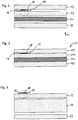
- Fig. 1 shows a film assembly in a first embodiment.
- the individual films are laminated by means of a laminating to the in Fig. 2 represented laminate body, which is a security document according to the invention 10 forms, joined together.
- Fig. 1 shown film assembly has a number of successive in a lamination 11 films.
- the film arrangement initially comprises a transparent film 12.
- a further film 14 is arranged which, depending on the embodiment, may be transparent or even opaque.
- the film 14 has a security feature 19 in a surface section.
- the area of the security feature 19 is in Fig. 1 marked with a broken circle.
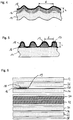
- FIG. 4 shows deisen area in an embodiment of the invention.
- Relieflack 16 is selected such that the applied to the film 14 resist layer is dimensionally stable under the conditions of a lamination process.
- the relief varnish 16 can also be selected as UV-curable varnish.
- the paint is irradiated after application to the film 14 with a UV light source and so the relief varnish 16 is fixed.
- the relief varnish 16 has a relief structure corresponding to the relief of the film 14.
- This relief structure has a feature size of greater than 2 microns.
- the relief lacquer forms a rigid protection for the embossed region of the film 14 and thus ensures that the relief of the film 14 is maintained in the following lamination process.
- the relief varnish 16 is screen-printed in the area of the security element 19 on the film 14, which in this case is flat.
- the lacquer layer 16 is formed from individual island-shaped relief elements 17.
- the relief elements 17 together form the relief structure.
- This relief structure also has a structure size of greater than 2 ⁇ m. Both the lateral distances d between the individual relief elements 17 and the respective height thereof are greater than 2 ⁇ m.
- the relief structure thus formed also remains dimensionally stable in the subsequent lamination process.
- the relief varnish 16 both according to Fig. 4 as well as according to Fig. 5 is coated with an optically variable color 18 in the form of an interference color.
- an interference color comprises so-called interference pigments which have at least one interference-capable, multilayer structure.
- the relief varnish 16 is coated with an effect color.
- the effect color may optionally or in combination have metal, gloss, pearlescent and / or mica.
- the relief structure formed according to the invention by means of the relief lacquer 16 is the basis for providing also the optically variable color 18 with a structure.
- the visual appearance of the optically variable color 18 is thus locally changed by structural changes, disturbances or inhomogeneities in the layer structure. The result is a clearly visible three-dimensional relief structure.
- the film 14 is printed with the optically variable ink 18.
- a coating is carried out with the relief varnish 16, which at least partially covers the optically variable ink.
- the film 14 formed at least locally transparent or translucent, so that the optically variable color 18 through the film 14 through the human eye is perceptible.
- an optically variable layer is not applied directly to the relief varnish 16 and thus to the film 14 but to the further film 12.
- the relief varnish 16 and the optically variable layer are arranged directly adjacent to each other and at least partially overlapping and possibly joined with further layers to form a monolithic laminate body.
- an optically variable color for example an interference color, can also be selected in this example.
- the relief lacquer 16 can be provided with a metal structure.
- a metal structure can be produced by writing fine structures in an embossing lacquer applied to the relief lacquer 16 or, if appropriate, directly in the relief lacquer 16. This is followed by vapor deposition with metal or a dielectric.
- the relief lacquer is part of a metal foil.
- the film arrangement according to Fig. 1 by means of a lamination process to that in Fig. 2 presented, the security document 10 forming monolithic laminate body fused.
- the laminate body then has layers formed from the corresponding films, which are designated by reference numerals 112, 114, 120 and 122.
- the security element 19 comprising the relief lacquer 16 and the optically variable color 18 is laminated on the inside in this embodiment.
- Fig. 5 shows another exemplary embodiment of a film assembly for producing a laminate body with an internally laminated security element 19.
- This film assembly comprises in this order three transparent films 12, 26 and 14 with a thickness of 100 microns each.
- the security element 19 having the relief lacquer 16 and the optically variable color 18 is arranged on the guilloche layer 18.
- the security element 19 is laminated and layered in all embodiments such that the optically variable color 18 is visible in plan view for the viewer and the relief varnish 16 is at least partially disposed below the optically variable color 18 and is concealed by it. Depending on the layering of the film arrangement, it is therefore necessary to arrange the desired motifs in mirror image on the films 14 and 12, respectively.
Landscapes
- Engineering & Computer Science (AREA)
- Manufacturing & Machinery (AREA)
- Health & Medical Sciences (AREA)
- Chemical & Material Sciences (AREA)
- Chemical Kinetics & Catalysis (AREA)
- General Chemical & Material Sciences (AREA)
- General Health & Medical Sciences (AREA)
- Toxicology (AREA)
- Credit Cards Or The Like (AREA)
- Laminated Bodies (AREA)
Description
- Die Erfindung betrifft ein Sicherheitsdokument mit einem aus mehreren Folien hergestellten monolithischen Laminatkörper sowie ein Verfahren zum Herstellen eines Sicherheitsdokuments. Derartige Sicherheitsdokumente werden oft auch als Verbundsicherheitsdokumente oder allgemein als Datenträger bezeichnet. In solche Sicherheitsdokumente können eine Vielzahl von Sicherheitsmerkmalen eingearbeitet werden, so dass diese als Identifikationsdokumente, z. B. als Personalausweise, Führerscheine, aber auch bei Reisepässen sowie weiteren Dokumenten zum Einsatz kommen, bei denen auf eine hohe Fälschungssicherheit Wert gelegt wird.
- Der monolithische Laminatkörper besteht aus mehreren in einem Laminationsprozess zu einem monolithischen Block verschmolzenen Schichtfolien. Die Sicherheitsdokumente weisen in der Regel quer zu einer Schichtungsrichtung der einzelnen Folien, die aufeinander laminiert werden, eine größere Ausdehnung auf als entlang der Schichtungsrichtung. Häufig liegen die Sicherheitsdokumente in Kartenform vor und werden als Chipkarten, insbesondere als Bankkarten, Kredit- oder Debitkarten, Bonuskarten und ähnliches eingesetzt. Derartige Chipkarten werden beispielsweise in der internationalen Norm ISO 7816 spezifiziert. Auch kontaktlose Karten z.B. gemäß dem internationalen Standard ISO 14443 werden als Sicherheitsdokument gemäß der vorliegenden Erfindung verstanden.
- Es ist bekannt, zum Schutz der beschriebenen Sicherheitsdokumente gegenüber Fälschung Effektfarben und/ oder außenliegende Reliefstrukturen vorzusehen. So ist in
DE 10 2007 037 982 A1 ein Verbundsicherheitsdokument beschrieben, welches zwischen zwei innenliegenden opaken Schichten eine aus einer Folie hergestellte Schicht mit einer Aussparung aufweist. Durch diese Aussparung ergibt sich eine an der Kartenoberfläche haptisch erkennbare hohl-reliefartige Struktur. Um die hohl-reliefartige Struktur optisch wahrnehmen zu können, ist in einem transparenten Oberflächenabschnitt des Laminatkörpers eine Interferenzfarbe eingebracht. Bei diesem vorbekannten Sicherheitsdokument ist jedoch problematisch, dass die optische Qualität des durch die hohl-reliefartige Struktur gebildeten Sicherheitsmerkmals oft unzureichend ist, wodurch das Sicherheitsmerkmal vielfach schlecht erkennbar ist. Das PatentdokumentDE 10 2005 045 567 A1 offenbart ein Sicherheitsdokument mit den Merkmalen des Oberbegriffs des Anspruchs 1. Es ist eine Aufgabe der Erfindung, ein Sicherheitsdokument der oben genannten Art sowie ein Verfahren zum Herstellen eines derartigen Sicherheitsdokuments bereitzustellen, womit die vorgenannten Probleme gelöst werden, und insbesondere die Fälschungssicherheit eines Sicherheitsdokuments verbessert werden kann. - Erfindungsgemäß wird die vorgenannte Aufgabe mit einem Sicherheitsdokument nach Anspruch 1, sowie das Verfahren nach Anspruch 15 gelöst. Unter einer Reliefstruktur ist eine erhabene Struktur zu verstehen. Gemäß einer vorteilhaften Ausführungsform weist die Reliefstruktur eine mehrstufige Topographie auf, d.h. es liegen mehrere Höhenniveaus innerhalb der Reliefstruktur vor. Erfindungsgemäß weist die Reliefstruktur eine Höhe oberhalb 2 µm, vorzugsweise oberhalb 10 µm auf und wird mithilfe von geeigneten Druckfarben und/ oder Lacken gebildet.
- Die Druckfarb- bzw. Lackschicht, die nachfolgend auch als Relieflack bezeichnet wird, ist unter den Bedingungen eines Laminierverfahrens formstabil. Es wird zwischen Heißlaminierung und Kaltlaminierung unterschieden. Während bei der Heißlaminierung die Folien eines herzustellenden Laminatkörpers bevorzugt auf Temperaturen von ≥ 150° C erwärmt und gleichzeitig mittels Druck aufeinander gepresst werden, wird ein Kaltlaminierverfahren ohne den Einsatz von Hitze durchgeführt. In diesem Fall werden jedoch in der Regel Klebstoffe eingesetzt, die für einen Verbund der einzelnen Folien sorgen. Der Druck wird jeweils parallel zu der Schichtungsrichtung der Folien aufgebracht.
- Mittels der erfindungsgemäßen Lackschicht ist es möglich, eine Reliefstruktur mit vergleichsweise großen Steigungsgradienten im Laminatkörper zu erzeugen. Die Reliefstruktur verändert das optische Erscheinungsbild des Laminatkörpers auf charakteristische Weise, insbesondere entsteht ein charakteristischer dreidimensionaler Eindruck. Dies ist besonders eindrucksvoll der Fall, wenn die Lackschicht beispielsweise mit einer optisch variablen Farbe oder einer Hologrammstruktur versehen wird. Die Erkennbarkeit einer derartigen optisch variablen Struktur kann durch die erfindungsgemäße Reliefstruktur wesentlich verbessert werden. Die Reliefstruktur verändert das optische Erscheinungsbild etwa einer optisch variablen Farbe durch strukturelle Änderungen, Störungen oder Inhomogenitäten im Schichtaufbau lokal.
- Erfindungsgemäß ist damit ein optisches Sicherheitsmerkmal geschaffen, dessen Überprüfung ohne spezielle Sachkenntnis möglich ist. Eine Echtheitsüberprüfung ist einfach und schnell durchführbar. Damit wird die Fälschungssicherheit des Sicherheitsdokuments wesentlich verbessert.
- In einer Ausführungsform nach der Erfindung ist die Lackschicht von einer optisch variablen Struktur bedeckt. Dabei grenzt die optisch variable Struktur unmittelbar an die Lackschicht an.
- Gemäß einer vorteilhaften Variante ist die optisch variable Struktur durch eine optisch variable Farbe gebildet. Insbesondere ist die optisch variable Farbe unmittelbar angrenzend auf die Reliefstruktur aufgebracht. Eine optisch variable Farbe erzeugt einen Farbkippeffekt, bei dem die Farbe abhängig vom Betrachtungswinkel variiert. Die Reliefstruktur erzeugt in Verbindung mit der optisch variablen Farbe bei einem festen Betrachtungswinkel einen optischen Effekt, der durch ein charakteristisches Farbspektrum gekennzeichnet ist. Dieser Effekt entsteht durch eine lokale Veränderung der Eigenschaft der optisch variablen Farbe infolge Verformung dieser Schicht. Zusätzlich tritt durch die Reliefstruktur eine Verstärkung der betrachtungswinkelabhängigen Änderung des Farbspektrums auf.
- Es kann nach einer Ausführungsform der Erfindung die optisch variable Farbe auf die Reliefstruktur aufgebracht werden, beispielsweise durch ein bekanntes Druckverfahren. Hierzu wird zur Bildung der Reliefstruktur zuerst die Lackschicht auf eine Folie gedruckt. In einem weiteren Schritt erfolgt das zumindest teilweise Überdrucken der Reliefstruktur mit der optisch variablen Farbe.
- Alternativ ist es auch denkbar, die Reliefstruktur in Form einer Lackschicht auf die optisch variable Farbe aufzubringen. Das Bedrucken der Folie erfolgt in einem ersten Schritt mit der optisch variablen Farbe. Den weiteren Schritt bildet das zumindest teilweise Überdrucken der optisch variablen Farbe mit der Lackschicht.
- Gemäß einer weiteren vorteilhaften Variante der Erfindung werden Reliefstruktur und optisch variable Struktur auf unterschiedlichen Folien aufgebracht und bei der Laminierung derart zusammengeführt, dass die optisch variable Struktur unmittelbar an die Lackschicht angrenzt und diese zumindest teilweise überdeckt. Durch den Vorgang des Laminierens ergibt sich eine dauerhafte Verbindung zwischen der Reliefstruktur und der optisch variablen Struktur, die auch bei sehr detailreichen Reliefstrukturen einen zufriedenstellenden optischen Effekt liefert.
- Eine optisch variable Farbe kann beispielsweise durch eine Interferenzfarbe gebildet werden. Eine derartige Interferenzfarbe umfasst sogenannte Interferenzpigmente, die mindestens einen interferenzfähigen, mehrschichtigen Aufbau aufweisen. Die Farbe ist mit einer derart geringen Flächendeckung gedruckt, dass sie im Durchlicht noch erhebliche Anteile des sichtbaren Lichts durchlässt. Die Interferenzpigmente können in einem Teilbereich mittels einer elektromagnetischen Strahlung, beispielsweise eines Lasers, irreversibel so verändert werden, dass sich in diesem Teilbereich der Interferenzeffekt visuell und/ oder maschinell deutlich erkennbar unterscheidet.
- In einer weiteren Ausführungsform nach der Erfindung kann auch eine weitere optisch variable Farbe als weitere Schicht oberhalb der ersten optisch variablen Farbe angeordnet werden und diese erste optisch variable Farbe ganz oder teilweise überdecken. Insbesondere kann diese weitere optisch variable Farbe ein Farbspektrum aufweisen, welches im wesentlichen komplementär zu dem Farbspektrum der ersten optisch variablen Farbe liegt.
- Gemäß einer alternativen Ausführungsform ist die optisch variable Struktur durch eine Farbe gebildet, die Metallpartikel und/ oder metallisierte Partikel enthält.
- Gemäß einer weiteren alternativen Ausführungsform der Erfindung ist die optisch variable Struktur durch eine Farbe gebildet, die magnetisierbare Partikel enthält.
- In einer weiteren Ausführungsform nach der Erfindung ist die von der Relieflackschicht gebildete Reliefstruktur derart konfiguriert, dass die Strukturelemente der Reliefstruktur mit dem bloßen Auge nicht auflösbar sind.
- In einer weiteren Ausführungsform nach der Erfindung ist die Reliefstruktur durch Dickenvariation des Relieflacks gebildet. Vorteilhafterweise wird der Relieflack im Siebdruckverfahren auf eine Trägerschicht aufgebracht. Als Ergebnis weist der Relieflack Dickenvariationen auf, die zumindest teilweise die Reliefstruktur bilden. Dabei kann die Dicke des Relieflacks im Sinne der Erfindung lokal auch Dicken von Null aufweisen; damit kann die Reliefstruktur auch durch inselförmige Lackabschnitte gebildet werden.
- In einer weiteren Ausführungsform nach der Erfindung weist die Relieflackschicht eine Pigmentierung auf. Auf diese Weise kann der Kontrast erhöht und der Reliefeffekt vergrößert werden. Erfindungsgemäß kann die Relieflackschicht dunkle, bevorzugt schwarze Pigmente enthalten, so dass der Kontrast zu der oder den optisch variablen Schichten erhöht wird.
- In einer weiteren Ausführungsform nach der Erfindung weist der Laminatkörper eine opake Schicht auf. Vorzugsweise weist die opake Schicht im Bereich der Projektion der Aussparung in Schichtungsrichtung ein transparentes Fenster auf. Damit kann die Reliefstruktur auch im Durchlicht betrachtet werden.
- In einer weiteren Ausführungsform nach der Erfindung weist das Sicherheitsdokument durch einen Laserstrahl eingebrachte Kennzeichnungen in Form von Mustern, Buchstaben, Zahlen und/ oder Bildern auf, die aufgrund von durch den Laserstrahl bewirkten, aus Materialumwandlungen resultierenden lokalen Änderungen der optischen Eigenschaften des Sicherheitsdokuments sichtbar sind. Hierzu kann die optisch variable Farbe lokal mit Laserlicht beaufschlagt werden.
- Die vorgenannte Aufgabe wird erfindungsgemäß weiterhin durch ein Verfahren zum Herstellen eines Sicherheitsdokuments gelöst, welches die folgenden Schritte aufweist: Aufbringen einer Relieflackschicht auf einer Trägerfolie derart, dass die Relieflackschicht eine Reliefstruktur mit einer Strukturgröße oberhalb 2 µm aufweist, Anordnen mindestens einer weiteren Folie oberhalb der Trägerfolie, sowie Laminieren der Folien mit einem Laminierverfahren zu einem monolithischen Laminatkörper.
- Die Relieflackschicht ist vorzugsweise derart formstabil, dass die Reliefstruktur bei dem Laminierverfahren erhalten bleibt. Hinsichtlich der Wirkungsweise des erfindungsgemäßen Verfahrens wird auf die vorstehenden Ausführungen zur Wirkungsweise des erfindungsgemäßen Sicherheitsdokuments verwiesen.
- Die bezüglich der vorstehend aufgeführten Ausführungsformen des erfindungsgemäßen Sicherheitsdokuments angegebenen Merkmale können entsprechend auf das erfindungsgemäße Verfahren übertragen werden. Umgekehrt können die bezüglich der vorstehend ausgeführten Ausführungsformen des erfindungsgemäßen Verfahrens angegebenen Merkmale entsprechend auf das erfindungsgemäße Sicherheitsdokument übertragen werden.
- Die vorstehenden, sowie weitere vorteilhafte Merkmale der Erfindung werden in der nachfolgenden detaillierten Beschreibung beispielhafter erfindungsgemäßer Ausführungsformen unter Bezugnahme auf die beigefügten schematischen Zeichnungen veranschaulicht. Es zeigt:
- Fig.1
- eine Schnittansicht einer Folienanordnung zur Herstellung eines Laminatkörpers in einer ersten Ausführungsform mit einer innenliegend laminierten Reliefstruktur;
- Fig. 2
- eine Schnittansicht eines aus der Folienanordnung gemäß
Fig. 1 durch einen Laminationsprozess hergestellten Laminatkörpers; - Fig. 3
- eine vergrößerte Ansicht der Reliefstruktur gemäß der
Figuren 1 bis 2 in einer Ausführungsform der nicht teil der Erfindung ist; - Fig. 4
- eine vergrößerte Ansicht der Reliefstruktur gemäß der
Figuren 1 bis 2 in einer zweiten Ausführungsform; sowie - Fig. 5
- eine Schnittansicht einer Folienanordnung zur Herstellung eines Laminatkörpers in einer dritten Ausführungsform mit einer innenliegend laminierten Reliefstruktur.
- In den nachstehend beschriebenen Ausführungsbeispielen sind funktionell oder strukturell einander ähnliche Elemente soweit wie möglich mit den gleichen oder ähnlichen Bezugszeichen versehen. Daher sollte zum Verständnis der Merkmale der einzelnen Elemente eines bestimmten Ausführungsbeispiels auf die Beschreibung anderer Ausführungsbeispiele oder die allgemeine Beschreibung der Erfindung Bezug genommen werden.
-
Fig. 1 zeigt eine Folienanordnung in einer ersten Ausführungsform. Die einzelnen Folien werden mittels eines Laminierverfahrens zu dem inFig. 2 dargestellten Laminatkörper, welcher ein erfindungsgemäßes Sicherheitsdokument 10 bildet, zusammengefügt. Die inFig. 1 gezeigte Folienanordnung weist eine Reihe von in einer Schichtungsrichtung 11 aufeinander folgenden Folien auf. - Von oben her beginnend umfasst die Folienanordnung zunächst eine transparente Folie 12. Unterhalb der Folie 12 ist eine weitere Folie 14 angeordnet, die je nach Ausführungsform transparent oder auch opak ausgebildet sein kann. Die Folie 14 weist in einem Flächenabschnitt ein Sicherheitsmerkmal 19 auf. Der Bereich des Sicherheitsmerkmals 19 ist in
Fig. 1 mit einem unterbrochenen Kreis gekennzeichnet.Figur 4 zeigt deisen Bereich in einer erfindungsgemäßen Ausführungsform. Relieflack 16 ist derart gewählt, dass die auf die Folie 14 aufgetragene Lackschicht unter den Bedingungen eines Laminierverfahrens formstabil ist. Gemäß einer Ausführungsform der Erfindung kann der Relieflack 16 auch als UV-härtbarer Lack gewählt werden. Hierzu wird der Lack nach dem Auftragen auf die Folie 14 mit einer UV-Lichtquelle bestrahlt und so der Relieflack 16 fixiert. - Durch das Lackieren der geprägten Folie 14 weist der Relieflack 16 eine dem Relief der Folie 14 entsprechende Reliefstruktur auf. Diese Reliefstruktur weist eine Strukturgröße von größer als 2 µm auf. Der Relieflack bildet einen starren Schutz für den geprägten Bereich der Folie 14 und sorgt damit dafür, dass bei dem folgenden Laminierverfahren das Relief der Folie 14 erhalten bleibt.
- In der Ausführungsform gemäß
Fig. 4 ist der Relieflack 16 im Siebdruckverfahren im Bereich des Sicherheitselements 19 auf die Folie 14, die in diesem Fall eben ist, aufgebracht. In der inFig. 4 gezeigten Ausführungsform wird die Lackschicht 16 aus einzelnen inselförmigen Reliefelementen 17 gebildet. Die Reliefelemente 17 bilden zusammen die Reliefstruktur. Auch diese Reliefstruktur weist eine Strukturgröße von größer als 2 µm auf. Sowohl die lateralen Abstände d zwischen den einzelnen Reliefelementen 17 als auch die jeweiligen Höhe derselben sind größer als 2 µm. Auch die derart gebildete Reliefstruktur bleibt bei dem nachfolgenden Laminierverfahren formstabil erhalten. - Der Relieflack 16 sowohl gemäß
Fig. 4 als auch gemäßFig. 5 wird mit einer optisch variablen Farbe 18 in Gestalt einer Interferenzfarbe beschichtet. Wie bereits vorstehend beschrieben, umfasst eine derartige Interferenzfarbe sogenannte Interferenzpigmente, die mindestens einen interferenzfähigen, mehrschichtigen Aufbau aufweisen. - Gemäß einer nicht dargestellten Ausführungsform der Erfindung wird der Relieflack 16 mit einer Effektfarbe beschichtet. Die Effektfarbe kann wahlweise oder in Kombination Metall-, Glanz-, Perlglanzpigmente und/ oder Glimmer aufweisen.
- Die erfindungsgemäß mittels des Relieflacks 16 gebildete Reliefstruktur ist die Basis dafür, dass auch die optisch variable Farbe 18 mit einer Struktur versehen wird. Das optische Erscheinungsbild der optisch variablen Farbe 18 wird damit durch strukturelle Änderungen, Störungen oder Inhomogenitäten im Schichtaufbau lokal verändert. Das Ergebnis ist eine gut sichtbare dreidimensionale Reliefstruktur.
- Gemäß einer alternativen Ausführungsform wird die Folie 14 mit der optisch variablen Farbe 18 bedruckt. In einem weiteren Schritt erfolgt eine Beschichtung mit dem Relieflack 16, die die optisch variable Farbe zumindest teilweise überdeckt. Zur Erzielung der gewünschten optischen Wirkung ist die Folie 14 zumindest lokal transparent bzw. transluzent ausgebildet, so dass die optisch variable Farbe 18 durch die Folie 14 hindurch für das menschliche Auge wahrnehmbar ist.
- Gemäß einer weiteren, nicht dargestellten Ausführungsform wird eine optisch variable Schicht nicht direkt auf dem Relieflack 16 und somit auf der Folie 14, sondern auf der weiteren Folie 12 aufgebracht. Bei dem sich anschließenden Laminierverfahren werden Relieflack 16 und optisch variable Schicht direkt aneinander angrenzend und sich zumindest teilweise überdeckend angeordnet und ggf. mit weiteren Schichten zu einem monolithischen Laminatkörper verbunden. Als optisch variable Schicht kann auch in diesem Beispiel eine optisch variable Farbe 18, beispielsweise eine Interferenzfarbe, gewählt werden. Ein Vorteil der Aufteilung des Relieflacks 16 und der optisch variablen Farbe 18 auf zwei unterschiedliche Folien liegt darin, den Druckprozess jeweils optimal steuern und den Relieflack 16 bzw. die optisch variable Farbe 18 unter jeweils angepassten Bedingungen aushärten zu lassen. Gerade bei sehr feinen, detailreichen Motiven ist dieses Verfahren von Vorteil. Die dreidimensionale Reliefstruktur entsteht bei dieser Ausführungsform erst mit der Laminierung beider Schichten.
- Alternativ zur optisch variablen Farbe 18 oder auch zusammen mit dieser kann der Relieflack 16 mit einer Metallstruktur versehen werden. Eine derartige Metallstruktur kann erzeugt werden, indem feine Strukturen in einen auf den Relieflack 16 aufgebrachten Prägelack oder ggf. direkt in den Relieflack 16 geschrieben werden. Daraufhin erfolgt eine Bedampfung mit Metall oder einem Dielektrikum. Gemäß einer erfindungsgemäßen Variante ist der Relieflack Teil einer Metallfolie.
- Wie bereits vorstehend erwähnt, wird die Folienanordnung gemäß
Fig. 1 mittels eines Laminierverfahrens zu dem inFig. 2 dargestellten, das Sicherheitsdokument 10 bildenden monolithischen Laminatkörper verschmolzen. Der Laminatkörper weist daraufhin aus den entsprechenden Folien gebildete Schichten auf, welche mit den Bezugszeichen 112,114,120 sowie 122 bezeichnet sind. Das den Relieflack 16 und die optisch variable Farbe 18 umfassende Sicherheitselement 19 ist in dieser Ausführungsform innenliegend laminiert angeordnet. -
Fig. 5 zeigt eine weitere beispielhafte Ausführungsform einer Folienanordnung zur Herstellung eines Laminatkörpers mit einem innenliegend laminierten Sicherheitselement 19. Diese Folienanordnung umfasst in dieser Reihenfolge drei transparente Folien 12, 26 und 14 mit einer Dicke von jeweils 100 µm. Auf der Oberseite der Folie 14 ist eine Guillochen-Schicht 28 angeordnet. Das den Relieflack 16 sowie die optisch variable Farbe 18 aufweisende Sicherheitselement 19 ist auf der Guillochenschicht 18 angeordnet. Dabei kann das Sicherheitselement 19 beispielsweise in einer der in denFiguren 4 und 5 dargestellten Ausführungsformen gestaltet sein. - Das Sicherheitselement 19 ist in allen Ausführungsformen derart laminiert und geschichtet, dass in Aufsicht für den Betrachter die optisch variable Farbe 18 sichtbar ist und der Relieflack 16 zumindest teilweise unterhalb der optisch variablen Farbe 18 angeordnet ist und durch diese verdeckt wird. Je nach Schichtung der Folienanordnung ist es daher erforderlich, die gewünschten Motive spiegelbildlich auf den Folien 14 bzw. 12 anzuordnen.
Claims (17)
- Sicherheitsdokument (10) mit einem aus mehreren aufeinander folgenden Folien hergestellten monolithischen Laminatkörper, dadurch gekennzeichnet, dass der Laminatkörper eine Lackschicht (16) aufweist, welche eine Reliefstruktur (17) bildet und unter den Bedingungen eines Laminierverfahrens formstabil ist, dadurch gekennzeichnet dass die Reliefstruktur innenliegend in der Laminatkörper ist und eine Strukturgröße von größer als 2 µm aufweist.
- Sicherheitsdokument nach Anspruch 1, dadurch gekennzeichnet, dass die Lackschicht von einer Effektfarbe bedeckt ist.
- Sicherheitsdokument nach Anspruch 1 dadurch gekennzeichnet, dass die Lackschicht von einer optisch variablen Struktur bedeckt ist.
- Sicherheitsdokument nach Anspruch 3, dadurch gekennzeichnet, dass die optisch variable Struktur durch eine erste optisch variable Farbe gebildet ist.
- Sicherheitsdokument nach Anspruch 3 oder 4 dadurch gekennzeichnet, dass die optisch variable Struktur durch wenigstens eine weitere optisch variable Farbe gebildet ist.
- Sicherheitsdokument nach Anspruch 3, dadurch gekennzeichnet, dass die optisch variable Struktur durch eine Farbe gebildet ist, welche Metallpartikel und/ oder metallisierte Partikel enthält.
- Sicherheitsdokument nach Anspruch 3, dadurch gekennzeichnet, dass die optisch variable Struktur durch eine Farbe gebildet ist, welche magnetisierbare Pigmente enthält.
- Sicherheitsdokument nach Anspruch 3, dadurch gekennzeichnet, dass die optisch variable Struktur durch eine Hologrammstruktur gebildet ist.
- Sicherheitsdokument nach wenigstens einem der Ansprüche 1 bis 8, dadurch gekennzeichnet, dass die von der Lackschicht gebildete Reliefstruktur derart konfiguriert ist, dass die Strukturelemente mit dem bloßen Auge nicht auflösbar sind.
- Sicherheitsdokument nach wenigstens einem der Ansprüche 1 bis 9, dadurch gekennzeichnet, dass die Lackschicht auf einer durch eine Folie gebildeten Trägerschicht angeordnet ist, wobei in die Trägerschicht eine der Reliefstruktur der Lackschicht entsprechende Reliefstruktur eingeprägt ist.
- Sicherheitsdokument nach wenigstens einem der Ansprüche 1 bis 10, dadurch gekennzeichnet, dass die Reliefstruktur durch Dickenvariation des Lacks gebildet ist.
- Sicherheitsdokument wenigstens einem der nach Ansprüche 1 bis 11, dadurch gekennzeichnet, dass die die Reliefstruktur bildende Lackschicht von einer vor dem Laminierverfahren als Folie aufgebrachten zumindest semi-transparenten Schicht bedeckt ist.
- Sicherheitsdokument nach wenigstens einem der Ansprüche 1 bis 12, dadurch gekennzeichnet, dass die die Reliefstruktur bildende Lackschicht an der Außenseite einer im Laminierverfahren aus Folien gebildeten Schichtenfolge angeordnet ist.
- Verfahren zum Herstellen eines Sicherheitsdokuments (10), mit den Schritten:- Aufbringen einer Lackschicht (16) auf einer Trägerfolie derart, dass die Lackschicht eine Reliefstruktur (17) mit einer Strukturgröße von größer als 2 µm aufweist,- Anordnen mindestens einer weiteren Folie oberhalb oder unterhalb der Trägerfolie, sowie- Laminieren der Folien zu einem monolithischen Laminatkörper, so dass der Laminatkörper ein innenliegendes Sicherheitselement (19) aufweist.
- Verfahren nach Anspruch 14, dadurch gekennzeichnet, dass vor dem Laminieren eine optisch variable Struktur auf die Lackschicht aufgebracht wird, derart, dass sich die optisch variable Struktur und die Lackschicht zumindest teilweise überdecken.
- Verfahren nach Anspruch 14, dadurch gekennzeichnet, dass vor dem Aufbringen der Lackschicht eine optisch variable Struktur auf die Trägerfolie aufgebracht wird, derart, dass sich die optisch variable Struktur und die Lackschicht zumindest teilweise überdecken.
- Verfahren nach Anspruch 14, dadurch gekennzeichnet, dass vor dem Laminieren eine optisch variable Struktur auf der mindestens einen weiteren Folie auf der der Lackschicht zugewandten Seite derart angebracht wird, dass die optisch variable Struktur der Lackschicht gegenüber liegt und nach dem Laminieren die Lackschicht zumindest teilweise überdeckt.
Applications Claiming Priority (1)
| Application Number | Priority Date | Filing Date | Title |
|---|---|---|---|
| DE102013021964.7A DE102013021964A1 (de) | 2013-12-20 | 2013-12-20 | Sicherheitsdokument sowie Verfahren zum Herstellen eines Sicherheitsdokuments |
Publications (3)
| Publication Number | Publication Date |
|---|---|
| EP2886357A2 EP2886357A2 (de) | 2015-06-24 |
| EP2886357A3 EP2886357A3 (de) | 2015-10-07 |
| EP2886357B1 true EP2886357B1 (de) | 2017-08-09 |
Family
ID=52100972
Family Applications (1)
| Application Number | Title | Priority Date | Filing Date |
|---|---|---|---|
| EP14004064.3A Active EP2886357B1 (de) | 2013-12-20 | 2014-12-02 | Sicherheitsdokument sowie Verfahren zum Herstellen eines Sicherheitsdokuments |
Country Status (2)
| Country | Link |
|---|---|
| EP (1) | EP2886357B1 (de) |
| DE (1) | DE102013021964A1 (de) |
Cited By (1)
| Publication number | Priority date | Publication date | Assignee | Title |
|---|---|---|---|---|
| DE102018112652A1 (de) * | 2018-05-25 | 2019-11-28 | Ovd Kinegram Ag | Verfahren zur Herstellung eines Laminatkörpers und einer Laminierfolie sowie Laminatkörper und Laminierfolie |
Families Citing this family (4)
| Publication number | Priority date | Publication date | Assignee | Title |
|---|---|---|---|---|
| DE102017006040A1 (de) | 2017-06-27 | 2018-12-27 | Giesecke+Devrient Mobile Security Gmbh | Sicherheitselement mit räumlich wirkendem Druckbild |
| EP3802144B1 (de) | 2018-05-25 | 2023-05-03 | OVD Kinegram AG | Verfahren zur herstellung eines laminatkörpers und einer laminierfolie sowie laminatkörper und laminierfolie |
| DE102022001819A1 (de) * | 2022-05-24 | 2023-11-30 | Giesecke+Devrient ePayments GmbH | Verfahren zur Herstellung eines Sicherheitsmerkmals, Sicherheitsmerkmal für einen Datenträger, Datenträger und Laminierblech |
| AT527002A1 (de) * | 2023-07-14 | 2024-08-15 | Hueck Folien Gmbh | Sicherheitselement für Wertpapiere, Sicherheitspapiere oder Sicherheitsgegenstände |
Family Cites Families (7)
| Publication number | Priority date | Publication date | Assignee | Title |
|---|---|---|---|---|
| DE102004022391A1 (de) * | 2004-05-06 | 2005-12-01 | Giesecke & Devrient Gmbh | Kartenschichtverbund |
| DE102005045567A1 (de) * | 2005-09-23 | 2007-03-29 | Giesecke & Devrient Gmbh | Verfahren zur Herstellung eines kartenförmigen Datenträgers |
| DE102006037431A1 (de) * | 2006-08-09 | 2008-04-17 | Ovd Kinegram Ag | Verfahren zur Herstellung eines Mehrschichtkörpers sowie Mehrschichtkörper |
| CN101541536A (zh) * | 2006-11-21 | 2009-09-23 | 西巴控股有限公司 | 用于制造安全产品的装置和方法 |
| DE102007037982A1 (de) | 2007-08-10 | 2009-02-12 | Bundesdruckerei Gmbh | Sicherheitsdokument mit wasserzeichenartiger Struktur |
| DE102009007778A1 (de) * | 2009-02-04 | 2010-08-05 | Bundesdruckerei Gmbh | Kunststoffbasierendes Wert- oder Sicherheitsdokument |
| US10479130B2 (en) * | 2009-07-24 | 2019-11-19 | Composecure, L.L.C. | Card with embedded image |
-
2013
- 2013-12-20 DE DE102013021964.7A patent/DE102013021964A1/de not_active Withdrawn
-
2014
- 2014-12-02 EP EP14004064.3A patent/EP2886357B1/de active Active
Non-Patent Citations (1)
| Title |
|---|
| None * |
Cited By (1)
| Publication number | Priority date | Publication date | Assignee | Title |
|---|---|---|---|---|
| DE102018112652A1 (de) * | 2018-05-25 | 2019-11-28 | Ovd Kinegram Ag | Verfahren zur Herstellung eines Laminatkörpers und einer Laminierfolie sowie Laminatkörper und Laminierfolie |
Also Published As
| Publication number | Publication date |
|---|---|
| DE102013021964A1 (de) | 2015-06-25 |
| EP2886357A2 (de) | 2015-06-24 |
| EP2886357A3 (de) | 2015-10-07 |
Similar Documents
| Publication | Publication Date | Title |
|---|---|---|
| EP2459387B1 (de) | Sicherheitselement für einen zu schützenden gegenstand sowie zu schützender gegenstand mit einem solchen sicherheitselement | |
| EP2665607B1 (de) | Verfahren zur herstellung eines mehrschichtigen datenträgers sowie nach diesem verfahren hergestellter datenträger | |
| EP3183124B1 (de) | Transferfolie sowie verfahren zur herstellung einer transferfolie | |
| EP2344342B1 (de) | Karte mit eingebettetem sicherheitselement | |
| EP3260302B1 (de) | Optisch variables sicherheitselement | |
| EP4112325B1 (de) | Sicherheitssubstrat und daraus hergestelltes wertdokument | |
| EP2393668B1 (de) | Sicherheitsmerkmal für dokument und herstellungsverfahren dessen | |
| DE102009053925A1 (de) | Sicherheitselement mit Mikrostruktur | |
| DE102009048145A1 (de) | Datenträger mit Fenster | |
| WO2014207165A1 (de) | Verfahren zur herstellung eines mehrschichtkörpers sowie mehrschichtkörper | |
| EP2886357B1 (de) | Sicherheitsdokument sowie Verfahren zum Herstellen eines Sicherheitsdokuments | |
| DE102015010945A1 (de) | Wertdokument | |
| EP3727871B1 (de) | Wertdokument | |
| DE102008028705B4 (de) | Verfahren zum Herstellen eines Wert- und/oder Sicherheitsdokuments sowie Wert- und/oder Sicherheitsdokument mit einer demetallisierten Struktur | |
| EP4461555A1 (de) | Sicherheitselement mit motivbildender flüssigkristallschicht | |
| EP4219182A2 (de) | Sicherheitselement, verfahren zum herstellen desselben und mit dem sicherheitselement ausgestatteter datenträger | |
| EP2886364B1 (de) | Sicherheitsdokument sowie Verfahren zum Herstellen eines Sicherheitsdokuments | |
| EP3609717B1 (de) | Sicherheitselement mit farbigem merkmalsbereich | |
| EP3418065B1 (de) | Mikrooptisches element mit farbwechsel | |
| EP3580068B1 (de) | Erzeugung eines optischen sicherheitselements | |
| EP3927561A1 (de) | Mehrschichtkörper sowie verfahren zur herstellung eines mehrschichtkörpers | |
| DE102006029397A1 (de) | Verfahren zur Herstellung eines laminierten Schichtverbunds, laminierter Schichtverbund und dessen Verwendung | |
| EP3666542B1 (de) | Verfahren zum herstellen eines laminats und laminat sowie sicherheits- oder wertdokument mit einem innenliegenden sicherheitsmerkmal | |
| DE102022129499A1 (de) | Sicherheitselement, Sicherheitsdokument und Verfahren zur Herstellung eines Sicherheitsdokuments | |
| EP1744878A1 (de) | Kartenschichtverbund |
Legal Events
| Date | Code | Title | Description |
|---|---|---|---|
| PUAI | Public reference made under article 153(3) epc to a published international application that has entered the european phase |
Free format text: ORIGINAL CODE: 0009012 |
|
| 17P | Request for examination filed |
Effective date: 20141202 |
|
| AK | Designated contracting states |
Kind code of ref document: A2 Designated state(s): AL AT BE BG CH CY CZ DE DK EE ES FI FR GB GR HR HU IE IS IT LI LT LU LV MC MK MT NL NO PL PT RO RS SE SI SK SM TR |
|
| AX | Request for extension of the european patent |
Extension state: BA ME |
|
| PUAL | Search report despatched |
Free format text: ORIGINAL CODE: 0009013 |
|
| AK | Designated contracting states |
Kind code of ref document: A3 Designated state(s): AL AT BE BG CH CY CZ DE DK EE ES FI FR GB GR HR HU IE IS IT LI LT LU LV MC MK MT NL NO PL PT RO RS SE SI SK SM TR |
|
| AX | Request for extension of the european patent |
Extension state: BA ME |
|
| RIC1 | Information provided on ipc code assigned before grant |
Ipc: B42D 25/324 20140101ALI20150902BHEP Ipc: B41M 3/14 20060101AFI20150902BHEP Ipc: B42D 25/21 20140101ALI20150902BHEP Ipc: B42D 25/378 20140101ALI20150902BHEP |
|
| R17P | Request for examination filed (corrected) |
Effective date: 20160407 |
|
| RBV | Designated contracting states (corrected) |
Designated state(s): AL AT BE BG CH CY CZ DE DK EE ES FI FR GB GR HR HU IE IS IT LI LT LU LV MC MK MT NL NO PL PT RO RS SE SI SK SM TR |
|
| RIC1 | Information provided on ipc code assigned before grant |
Ipc: B42D 25/324 20140101ALI20170125BHEP Ipc: B42D 25/47 20140101ALI20170125BHEP Ipc: B42D 25/369 20140101ALI20170125BHEP Ipc: B42D 25/425 20140101ALI20170125BHEP Ipc: B41M 3/14 20060101AFI20170125BHEP Ipc: B42D 25/373 20140101ALI20170125BHEP Ipc: B42D 25/378 20140101ALI20170125BHEP Ipc: B42D 25/328 20140101ALI20170125BHEP Ipc: B32B 37/18 20060101ALI20170125BHEP Ipc: B42D 25/21 20140101ALI20170125BHEP Ipc: B42D 25/46 20140101ALI20170125BHEP Ipc: B32B 37/24 20060101ALI20170125BHEP Ipc: B42D 25/455 20140101ALI20170125BHEP |
|
| GRAP | Despatch of communication of intention to grant a patent |
Free format text: ORIGINAL CODE: EPIDOSNIGR1 |
|
| INTG | Intention to grant announced |
Effective date: 20170323 |
|
| GRAS | Grant fee paid |
Free format text: ORIGINAL CODE: EPIDOSNIGR3 |
|
| GRAA | (expected) grant |
Free format text: ORIGINAL CODE: 0009210 |
|
| AK | Designated contracting states |
Kind code of ref document: B1 Designated state(s): AL AT BE BG CH CY CZ DE DK EE ES FI FR GB GR HR HU IE IS IT LI LT LU LV MC MK MT NL NO PL PT RO RS SE SI SK SM TR |
|
| REG | Reference to a national code |
Ref country code: GB Ref legal event code: FG4D Free format text: NOT ENGLISH |
|
| REG | Reference to a national code |
Ref country code: CH Ref legal event code: EP Ref country code: AT Ref legal event code: REF Ref document number: 916378 Country of ref document: AT Kind code of ref document: T Effective date: 20170815 |
|
| RAP2 | Party data changed (patent owner data changed or rights of a patent transferred) |
Owner name: GIESECKE+DEVRIENT MOBILE SECURITY GMBH |
|
| REG | Reference to a national code |
Ref country code: IE Ref legal event code: FG4D Free format text: LANGUAGE OF EP DOCUMENT: GERMAN |
|
| REG | Reference to a national code |
Ref country code: DE Ref legal event code: R096 Ref document number: 502014004871 Country of ref document: DE |
|
| REG | Reference to a national code |
Ref country code: AT Ref legal event code: HC Ref document number: 916378 Country of ref document: AT Kind code of ref document: T Owner name: GIESECKE+DEVRIENT MOBILE SECURITY GMBH, DE Effective date: 20170918 |
|
| REG | Reference to a national code |
Ref country code: NL Ref legal event code: MP Effective date: 20170809 |
|
| REG | Reference to a national code |
Ref country code: FR Ref legal event code: PLFP Year of fee payment: 4 |
|
| REG | Reference to a national code |
Ref country code: LT Ref legal event code: MG4D |
|
| PG25 | Lapsed in a contracting state [announced via postgrant information from national office to epo] |
Ref country code: SE Free format text: LAPSE BECAUSE OF FAILURE TO SUBMIT A TRANSLATION OF THE DESCRIPTION OR TO PAY THE FEE WITHIN THE PRESCRIBED TIME-LIMIT Effective date: 20170809 Ref country code: NL Free format text: LAPSE BECAUSE OF FAILURE TO SUBMIT A TRANSLATION OF THE DESCRIPTION OR TO PAY THE FEE WITHIN THE PRESCRIBED TIME-LIMIT Effective date: 20170809 Ref country code: FI Free format text: LAPSE BECAUSE OF FAILURE TO SUBMIT A TRANSLATION OF THE DESCRIPTION OR TO PAY THE FEE WITHIN THE PRESCRIBED TIME-LIMIT Effective date: 20170809 Ref country code: NO Free format text: LAPSE BECAUSE OF FAILURE TO SUBMIT A TRANSLATION OF THE DESCRIPTION OR TO PAY THE FEE WITHIN THE PRESCRIBED TIME-LIMIT Effective date: 20171109 Ref country code: HR Free format text: LAPSE BECAUSE OF FAILURE TO SUBMIT A TRANSLATION OF THE DESCRIPTION OR TO PAY THE FEE WITHIN THE PRESCRIBED TIME-LIMIT Effective date: 20170809 Ref country code: LT Free format text: LAPSE BECAUSE OF FAILURE TO SUBMIT A TRANSLATION OF THE DESCRIPTION OR TO PAY THE FEE WITHIN THE PRESCRIBED TIME-LIMIT Effective date: 20170809 |
|
| PG25 | Lapsed in a contracting state [announced via postgrant information from national office to epo] |
Ref country code: GR Free format text: LAPSE BECAUSE OF FAILURE TO SUBMIT A TRANSLATION OF THE DESCRIPTION OR TO PAY THE FEE WITHIN THE PRESCRIBED TIME-LIMIT Effective date: 20171110 Ref country code: RS Free format text: LAPSE BECAUSE OF FAILURE TO SUBMIT A TRANSLATION OF THE DESCRIPTION OR TO PAY THE FEE WITHIN THE PRESCRIBED TIME-LIMIT Effective date: 20170809 Ref country code: PL Free format text: LAPSE BECAUSE OF FAILURE TO SUBMIT A TRANSLATION OF THE DESCRIPTION OR TO PAY THE FEE WITHIN THE PRESCRIBED TIME-LIMIT Effective date: 20170809 Ref country code: LV Free format text: LAPSE BECAUSE OF FAILURE TO SUBMIT A TRANSLATION OF THE DESCRIPTION OR TO PAY THE FEE WITHIN THE PRESCRIBED TIME-LIMIT Effective date: 20170809 Ref country code: BG Free format text: LAPSE BECAUSE OF FAILURE TO SUBMIT A TRANSLATION OF THE DESCRIPTION OR TO PAY THE FEE WITHIN THE PRESCRIBED TIME-LIMIT Effective date: 20171109 Ref country code: IS Free format text: LAPSE BECAUSE OF FAILURE TO SUBMIT A TRANSLATION OF THE DESCRIPTION OR TO PAY THE FEE WITHIN THE PRESCRIBED TIME-LIMIT Effective date: 20171209 Ref country code: ES Free format text: LAPSE BECAUSE OF FAILURE TO SUBMIT A TRANSLATION OF THE DESCRIPTION OR TO PAY THE FEE WITHIN THE PRESCRIBED TIME-LIMIT Effective date: 20170809 |
|
| PG25 | Lapsed in a contracting state [announced via postgrant information from national office to epo] |
Ref country code: CZ Free format text: LAPSE BECAUSE OF FAILURE TO SUBMIT A TRANSLATION OF THE DESCRIPTION OR TO PAY THE FEE WITHIN THE PRESCRIBED TIME-LIMIT Effective date: 20170809 Ref country code: RO Free format text: LAPSE BECAUSE OF FAILURE TO SUBMIT A TRANSLATION OF THE DESCRIPTION OR TO PAY THE FEE WITHIN THE PRESCRIBED TIME-LIMIT Effective date: 20170809 Ref country code: DK Free format text: LAPSE BECAUSE OF FAILURE TO SUBMIT A TRANSLATION OF THE DESCRIPTION OR TO PAY THE FEE WITHIN THE PRESCRIBED TIME-LIMIT Effective date: 20170809 |
|
| REG | Reference to a national code |
Ref country code: DE Ref legal event code: R097 Ref document number: 502014004871 Country of ref document: DE |
|
| PG25 | Lapsed in a contracting state [announced via postgrant information from national office to epo] |
Ref country code: IT Free format text: LAPSE BECAUSE OF FAILURE TO SUBMIT A TRANSLATION OF THE DESCRIPTION OR TO PAY THE FEE WITHIN THE PRESCRIBED TIME-LIMIT Effective date: 20170809 Ref country code: SK Free format text: LAPSE BECAUSE OF FAILURE TO SUBMIT A TRANSLATION OF THE DESCRIPTION OR TO PAY THE FEE WITHIN THE PRESCRIBED TIME-LIMIT Effective date: 20170809 Ref country code: EE Free format text: LAPSE BECAUSE OF FAILURE TO SUBMIT A TRANSLATION OF THE DESCRIPTION OR TO PAY THE FEE WITHIN THE PRESCRIBED TIME-LIMIT Effective date: 20170809 Ref country code: SM Free format text: LAPSE BECAUSE OF FAILURE TO SUBMIT A TRANSLATION OF THE DESCRIPTION OR TO PAY THE FEE WITHIN THE PRESCRIBED TIME-LIMIT Effective date: 20170809 |
|
| PLBE | No opposition filed within time limit |
Free format text: ORIGINAL CODE: 0009261 |
|
| STAA | Information on the status of an ep patent application or granted ep patent |
Free format text: STATUS: NO OPPOSITION FILED WITHIN TIME LIMIT |
|
| 26N | No opposition filed |
Effective date: 20180511 |
|
| REG | Reference to a national code |
Ref country code: FR Ref legal event code: TP Owner name: GIESECKE+DEVRIENT MOBILE SECURITY GMBH, DE Effective date: 20180619 |
|
| REG | Reference to a national code |
Ref country code: CH Ref legal event code: PL |
|
| PG25 | Lapsed in a contracting state [announced via postgrant information from national office to epo] |
Ref country code: SI Free format text: LAPSE BECAUSE OF FAILURE TO SUBMIT A TRANSLATION OF THE DESCRIPTION OR TO PAY THE FEE WITHIN THE PRESCRIBED TIME-LIMIT Effective date: 20170809 |
|
| REG | Reference to a national code |
Ref country code: IE Ref legal event code: MM4A |
|
| PG25 | Lapsed in a contracting state [announced via postgrant information from national office to epo] |
Ref country code: MT Free format text: LAPSE BECAUSE OF FAILURE TO SUBMIT A TRANSLATION OF THE DESCRIPTION OR TO PAY THE FEE WITHIN THE PRESCRIBED TIME-LIMIT Effective date: 20170809 Ref country code: LU Free format text: LAPSE BECAUSE OF NON-PAYMENT OF DUE FEES Effective date: 20171202 |
|
| REG | Reference to a national code |
Ref country code: BE Ref legal event code: MM Effective date: 20171231 |
|
| PG25 | Lapsed in a contracting state [announced via postgrant information from national office to epo] |
Ref country code: IE Free format text: LAPSE BECAUSE OF NON-PAYMENT OF DUE FEES Effective date: 20171202 |
|
| PG25 | Lapsed in a contracting state [announced via postgrant information from national office to epo] |
Ref country code: CH Free format text: LAPSE BECAUSE OF NON-PAYMENT OF DUE FEES Effective date: 20171231 Ref country code: BE Free format text: LAPSE BECAUSE OF NON-PAYMENT OF DUE FEES Effective date: 20171231 Ref country code: LI Free format text: LAPSE BECAUSE OF NON-PAYMENT OF DUE FEES Effective date: 20171231 |
|
| PG25 | Lapsed in a contracting state [announced via postgrant information from national office to epo] |
Ref country code: MC Free format text: LAPSE BECAUSE OF FAILURE TO SUBMIT A TRANSLATION OF THE DESCRIPTION OR TO PAY THE FEE WITHIN THE PRESCRIBED TIME-LIMIT Effective date: 20170809 Ref country code: HU Free format text: LAPSE BECAUSE OF FAILURE TO SUBMIT A TRANSLATION OF THE DESCRIPTION OR TO PAY THE FEE WITHIN THE PRESCRIBED TIME-LIMIT; INVALID AB INITIO Effective date: 20141202 |
|
| GBPC | Gb: european patent ceased through non-payment of renewal fee |
Effective date: 20181202 |
|
| PG25 | Lapsed in a contracting state [announced via postgrant information from national office to epo] |
Ref country code: CY Free format text: LAPSE BECAUSE OF FAILURE TO SUBMIT A TRANSLATION OF THE DESCRIPTION OR TO PAY THE FEE WITHIN THE PRESCRIBED TIME-LIMIT Effective date: 20170809 |
|
| PG25 | Lapsed in a contracting state [announced via postgrant information from national office to epo] |
Ref country code: MK Free format text: LAPSE BECAUSE OF FAILURE TO SUBMIT A TRANSLATION OF THE DESCRIPTION OR TO PAY THE FEE WITHIN THE PRESCRIBED TIME-LIMIT Effective date: 20170809 |
|
| PG25 | Lapsed in a contracting state [announced via postgrant information from national office to epo] |
Ref country code: GB Free format text: LAPSE BECAUSE OF NON-PAYMENT OF DUE FEES Effective date: 20181202 |
|
| PG25 | Lapsed in a contracting state [announced via postgrant information from national office to epo] |
Ref country code: TR Free format text: LAPSE BECAUSE OF FAILURE TO SUBMIT A TRANSLATION OF THE DESCRIPTION OR TO PAY THE FEE WITHIN THE PRESCRIBED TIME-LIMIT Effective date: 20170809 |
|
| PG25 | Lapsed in a contracting state [announced via postgrant information from national office to epo] |
Ref country code: PT Free format text: LAPSE BECAUSE OF FAILURE TO SUBMIT A TRANSLATION OF THE DESCRIPTION OR TO PAY THE FEE WITHIN THE PRESCRIBED TIME-LIMIT Effective date: 20170809 |
|
| PG25 | Lapsed in a contracting state [announced via postgrant information from national office to epo] |
Ref country code: AL Free format text: LAPSE BECAUSE OF FAILURE TO SUBMIT A TRANSLATION OF THE DESCRIPTION OR TO PAY THE FEE WITHIN THE PRESCRIBED TIME-LIMIT Effective date: 20170809 |
|
| REG | Reference to a national code |
Ref country code: AT Ref legal event code: MM01 Ref document number: 916378 Country of ref document: AT Kind code of ref document: T Effective date: 20191202 |
|
| PG25 | Lapsed in a contracting state [announced via postgrant information from national office to epo] |
Ref country code: AT Free format text: LAPSE BECAUSE OF NON-PAYMENT OF DUE FEES Effective date: 20191202 |
|
| P01 | Opt-out of the competence of the unified patent court (upc) registered |
Effective date: 20230520 |
|
| REG | Reference to a national code |
Ref country code: DE Ref legal event code: R081 Ref document number: 502014004871 Country of ref document: DE Owner name: GIESECKE+DEVRIENT EPAYMENTS GMBH, DE Free format text: FORMER OWNER: GIESECKE+DEVRIENT MOBILE SECURITY GMBH, 81677 MUENCHEN, DE |
|
| PGFP | Annual fee paid to national office [announced via postgrant information from national office to epo] |
Ref country code: FR Payment date: 20251218 Year of fee payment: 12 |
|
| PGFP | Annual fee paid to national office [announced via postgrant information from national office to epo] |
Ref country code: DE Payment date: 20251222 Year of fee payment: 12 |