EP2885656B1 - Verfahren zur abbildung von seismischen daten - Google Patents
Verfahren zur abbildung von seismischen daten Download PDFInfo
- Publication number
- EP2885656B1 EP2885656B1 EP12886507.8A EP12886507A EP2885656B1 EP 2885656 B1 EP2885656 B1 EP 2885656B1 EP 12886507 A EP12886507 A EP 12886507A EP 2885656 B1 EP2885656 B1 EP 2885656B1
- Authority
- EP
- European Patent Office
- Prior art keywords
- tti
- propagation value
- side wavefield
- wavefield propagation
- hybrid
- Prior art date
- Legal status (The legal status is an assumption and is not a legal conclusion. Google has not performed a legal analysis and makes no representation as to the accuracy of the status listed.)
- Not-in-force
Links
Images


Classifications
-
- G—PHYSICS
- G01—MEASURING; TESTING
- G01V—GEOPHYSICS; GRAVITATIONAL MEASUREMENTS; DETECTING MASSES OR OBJECTS; TAGS
- G01V1/00—Seismology; Seismic or acoustic prospecting or detecting
- G01V1/28—Processing seismic data, e.g. for interpretation or for event detection
- G01V1/282—Application of seismic models, synthetic seismograms
-
- G—PHYSICS
- G06—COMPUTING OR CALCULATING; COUNTING
- G06T—IMAGE DATA PROCESSING OR GENERATION, IN GENERAL
- G06T7/00—Image analysis
- G06T7/50—Depth or shape recovery
-
- G—PHYSICS
- G06—COMPUTING OR CALCULATING; COUNTING
- G06V—IMAGE OR VIDEO RECOGNITION OR UNDERSTANDING
- G06V30/00—Character recognition; Recognising digital ink; Document-oriented image-based pattern recognition
- G06V30/40—Document-oriented image-based pattern recognition
- G06V30/42—Document-oriented image-based pattern recognition based on the type of document
- G06V30/422—Technical drawings; Geographical maps
-
- G—PHYSICS
- G01—MEASURING; TESTING
- G01V—GEOPHYSICS; GRAVITATIONAL MEASUREMENTS; DETECTING MASSES OR OBJECTS; TAGS
- G01V2210/00—Details of seismic processing or analysis
- G01V2210/50—Corrections or adjustments related to wave propagation
- G01V2210/51—Migration
- G01V2210/512—Pre-stack
-
- G—PHYSICS
- G01—MEASURING; TESTING
- G01V—GEOPHYSICS; GRAVITATIONAL MEASUREMENTS; DETECTING MASSES OR OBJECTS; TAGS
- G01V2210/00—Details of seismic processing or analysis
- G01V2210/50—Corrections or adjustments related to wave propagation
- G01V2210/58—Media-related
- G01V2210/586—Anisotropic media
Definitions
- the present invention generally relates to systems and methods for imaging seismic data. More particularly, the present invention relates to imaging seismic data using hybrid one-way wave equation migration in tilted transverse isotropic media ("hybrid TTI-WEM”) and/or hybrid two-way reverse time migration in tilted transverse isotropic media (“hybrid TTI-RTM”).
- TTI tilted transverse isotropic
- RTM reverse time migration
- TTI-RTM propagates a source wave field forward in time and a receiver wave field backward in time to image the subsurface reflector by any well-known two-way wave equation such as the two-way wave equation described in the paper “ Reverse Time Migration: Geophysics” by Baysal , et al. and in the paper “ Migration by Extrapolation of Time-Dependent Boundary Values: Geophysical Prospecting” by G. A. McMechan .
- wave equation migration and/or reverse time migration are referred to herein as two-way, they may also be referred to as full-way.
- a one-way wave equation can provide faster processing and handle strong lateral velocity variation.
- One-way wave equations such as a Finite Difference propagator, a Phase-Shift-Plus-Interpolation propagator, and/or a Generalized Screen propagator, demonstrate good accuracy in general.
- WEM isotropic wave equation migration
- a hybrid propagator for prestack migration in isotropic media was developed and is described in the paper "Hybrid One-Way and Full-Way Wave Equation Propagator and Prestack Migration" by Luo and Jin (" Luo and Jin ").
- the hybrid propagator combines one-way and two-way WEM to extrapolate a wavefield progressively. In this manner, a one-way propagator may be applied to less complex media while the two-way propagator may be applied to extremely complicated media.
- the Luo and Jin hybrid propagator in isotropic media generates comparable image results with two-way WEM for RTM with less noise and computational costs, it has not been applied to TTI media.
- the Luo and Jin hybrid propagator does not contemplate the use of Padé approximation, which could provide maximum accuracy for wave propagation.
- the present invention therefore, meets the above needs and overcomes one or more deficiencies in the prior art by providing systems and methods for imaging seismic data using hybrid TTI-WEM and/or hybrid TTI-RTM.
- the present invention includes a method for imaging seismic data, which comprises: i) approximating TTI coefficients using a Padé approximation and a dispersion relation equation; ii) applying hybrid TTI-WEM to a velocity model and anisotropic parameters for a pre-stack shot gather using the approximated TTI coefficients and a computer system to determine a source side wavefield propagation value and a receiver side wavefield propagation value in a frequency-space domain; iii) converting the source side wavefield propagation value and the receiver side wavefield propagation value from the frequency-space domain to a time-space domain; and iv) applying a zero-lag cross-correlation image condition equation to form a partial output image using the converted source side wavefield propagation value and the converted receiver side wavefield propagation value.
- the present invention includes a non-transitory program carrier device tangibly carrying computer executable instructions for imaging seismic data, the instructions being executable to implement: i) approximating TTI coefficients using a Padé approximation and a dispersion relation equation; ii) applying hybrid TTI-WEM to a velocity model and anisotropic parameters for a pre-stack shot gather using the approximated TTI coefficients and a computer system to determine a source side wavefield propagation value and a receiver side wavefield propagation value in a frequency-space domain; iii) converting the source side wavefield propagation value and the receiver side wavefield propagation value from the frequency-space domain to a time-space domain; and iv) applying a zero-lag cross-correlation image condition equation to form a partial output image using the converted source side wavefield propagation value and the converted receiver side wavefield propagation value.
- the present invention significantly reduces the computational time associated with conventional two-way TTI-RTM by applying a hybrid TTI-WEM with an implicit finite difference algorithm and by applying a hybrid TTI-RTM with an explicit finite difference algorithm.
- the present invention also provides better image quality with less artifacts and can also handle geological topography naturally.
- FIG. 1 a flow diagram of one embodiment of a method 100 for implementing the present invention is illustrated.
- seismic survey data such as, for example, prestack shot gathers in time-space ("T-X") domain
- a velocity model and anisotropic parameters such as, for example, epsilon ( ⁇ ), delta ( ⁇ ), tilted dip angle ( ⁇ ) and azimuth angle ( ⁇ ) are input using the client interface and/or the video interface described further in reference to FIG. 6 .
- a migration depth is set between the hybrid TTI-WEM and the hybrid TTI-RTM using the client interface and/or the video interface described further in reference to FIG. 6 .
- the migration depth may be used to separate the velocity model and anisotropic parameters into an area where the hybrid TTI-WEM will be applied from a surface of the earth to the migration depth below the surface and an area where the hybrid TTI-RTM will be applied below the migration depth to an extent of the velocity model.
- a prestack shot gather is selected from the prestack shot gathers in step 101 using the client interface and/or video interface described further in reference to FIG. 6 .
- the prestack shot gather may be selected automatically. In either event, it may be selected at random or in any other predetermined manner.
- step 103 the method 100 determines if the migration depth is zero. If the migration depth is zero, then the method 100 proceeds to step 111 where only the hybrid TTI-RTM will be applied in the T-X domain to the prestack shot gather selected in step 102b using the velocity model and anisotropic parameters from a surface of the earth to the extent of the velocity model.
- step 104 the hybrid TTI-WEM will be applied in the frequency-space ("F-X") domain to the prestack shot gather selected in step 102b using the velocity model and anisotropic parameters from a surface of the earth to the migration depth and the hybrid TTI-RTM will be applied in the T-X domain to the prestack shot gather selected in step 102b using the velocity model and anisotropic parameters from the migration depth to the extent of the velocity model.
- F-X frequency-space
- step 104 the prestack shot gather selected in step 102b is converted from its native T-X domain to the F-X domain using techniques well-known in the art such as, for example, a fast fourier transform (“FFT”) algorithm.
- FFT fast fourier transform
- a TTI dispersion relation equation which is also be referred to as a quartic equation, is created from the well-known phase velocity function and rotation matrix.
- step 106 TTI coefficients are approximated using the TTI dispersion relation equation (1).
- One embodiment of a method 500 for approximating the TTI coefficients is described further in reference to FIG. 5 .
- a hybrid TTI-WEM and/or a well-known phase shift algorithm are applied in the F-X domain to the velocity model and anisotropic parameters for the prestack shot gather selected in step 102b. If water is present in the velocity model and the migration depth is not below a subsurface where the water meets the earth, then only the phase shift algorithm is applied. If water is present in the velocity model and the migration depth is below a subsurface where the water meets the earth, then the hybrid TTI-WEM and the phase shift algorithm are applied. If water is not present in the velocity model, then only the hybrid TTI-WEM is applied. Because the velocity of water is a known constant, the anisotropic parameters are all zero when applying the phase shift algorithm.
- the hybrid TTI-WEM is applied from a surface of the earth or a subsurface where the water meets the earth to the migration depth.
- the phase shift algorithm is only applied from a water surface to a subsurface where the water meets the earth.
- the input is gather (t, x, y), which is the prestack shot gather selected in step 102b.
- P 2 (iw, ix, iy, iz) P 2 (iw, ix, iy, iz) + gather (iw, ix, iy), which is used to solve for P 2 in equation (3.1).
- P 1 and P 2 may be used as the input in equation (3.1) to solve for P 1 and P 2 when applying TTI-WEM in the FX-domain instead of using the assumed P 1 and P 2 described hereinabove when only hybrid TTI-WEM is applied.
- step 109 the source side wavefield propagation value (P 1 ) and the receiver side wavefield propagation value (P 2 ) from the hybrid TTI-WEM and/or the phase shift algorithm in step 107 are converted from the F-X domain to the T-X domain using techniques well-known in the art such as, for example, an inverse fast fourier transform (“IFFT”) algorithm.
- IFFT inverse fast fourier transform
- step 110 the following zero-lag cross-correlation image condition equation is applied to form a partial output image (I time (x, y, z)) using P 1 and P 2 from the hybrid TTI-WEM and/or the phase shift algorithm in step 107:
- a hybrid TTI-RTM is applied in the T-X domain to the velocity model and anisotropic parameters for the prestack shot gather selected in step 102b.
- the hybrid TTI-RTM is applied from the migration depth, which may be a surface of the earth if it is zero, to the extent of the velocity model.
- M ′ 1 ⁇ sin 2 ⁇ cos 2 ⁇ ⁇ 2 ⁇ x 2 + 1 ⁇ sin 2 ⁇ sin 2 ⁇ ⁇ 2 ⁇ y 2 + sin 2 ⁇ ⁇ 2 ⁇ z 2 ⁇ sin 2 ⁇ sin ⁇ ⁇ 2 ⁇ y ⁇ z ⁇ sin 2 ⁇ cos ⁇ ⁇ 2 ⁇ x
- Equation (5) thus, may be solved using a well-known explicit FD algorithm in the manner described in International Patent Application Publication No. WO/2011/053327 .
- equations (1) and (8) become hybrid VTI-RTM schemes, when ⁇ , ⁇ , ⁇ , and ⁇ are all set to zero, they will become traditional hybrid isotropic RTM schemes.
- step 112 the zero-lag cross-correlation image condition equation (4) is applied to form a partial output image (I time (x, y, z)) using P 1 and P 2 from the hybrid TTI-RTM in step 111.
- step 113 low wave number and migration artifacts are removed from the partial output images in steps 110 and 112 by filtering and smoothing to generate amplitude consistent partial output images.
- a well-known low-wave number filter is applied to the partial output images from steps 110 and 112, then each filtered partial output image is divided by the source-side wavefield propagation value P 1 from step 111 to generate the amplitude consistent partial output images.
- step 114 the method 100 determines if there are more prestack shot gathers from the seismic survey data in step 101. If there are more prestack shot gathers, then the method 100 returns to step 102b to select another prestack shot gather. If there are no more prestack shot gathers, then the method 100 proceeds to step 115.
- step 115 the amplitude consistent partial output images from each iteration of step 113 are stacked and displayed using techniques well-known in the art. As a result, noise will be significantly cancelled and the final image will be enhanced.
- FIG. 5 one embodiment of a method 500 is illustrated for performing step 106 in FIG. 1 .
- step 502 a Jenkins-Traub algorithm is applied to equation (1) to solve for T z which represents polynomial zeros that relate to a down-going P-wave.
- step 506 a least square optimization method is applied to equation (6), which forms equation (7) and is solved for ⁇ j and ⁇ i to ultimately approximate the TTI coefficients.
- the maximum propagation angle is up to 50°.
- the upper limit of T x and T y for least square optimization is less than +0.85 and the lower limit of T x and T y is greater than - 0.85.
- the maximum propagation angle is up to 70°.
- the upper limit of T x and T y for least square optimization is less than +0.90 and the lower limit of T x and T y is greater than -0.90. Because the hybrid TTI-WEM may be applied in shallow places, second order approximation is satisfactory for good image quality, however, any order for approximation could be used. In this manner, a large propagation angle is obtainable over other well-known methods that produces better image quality.
- T z T z 0 ⁇ a 1 T x 2 + c 1 T x 1 ⁇ b 1 T x 2 ⁇ a 2 T y 2 + c 2 T y 1 ⁇ b 2 T y 2
- the TTI coefficients ( a i , b i , c i ) from equation (8) may be saved in respective tables before applying the hybrid TTI-WEM.
- hybrid TTI-RTM and conventional two-way TTI-RTM are applied to offshore data for a comparison of their resulting images.
- a phase shift algorithm was applied according to step 107 in FIG. 1 from a water surface to a subsurface where the water meets the earth.
- the hybrid TTI-WEM was applied according to step 107 in FIG. 1 from the subsurface to a migration depth of 2 km.
- the hybrid TTI-WEM was applied from 2 km to the extent of the velocity model at 16 km according to step 111 in FIG. 1 .
- An image of the velocity model is illustrated in FIG. 2A .
- the anisotropic parameters for the velocity model in FIG. 2A are illustrated in FIGS. 2B ( ⁇ ), 2C ( ⁇ ) and 2D ( ⁇ ).
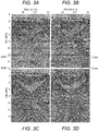
- the application of the hybrid TTI-RTM as a result of the method 100 in FIG. 1 produces a much cleaner and clearer image ( FIG. 3C ) than the images produced by conventional techniques in isotropic media ( FIG. 3A ) and conventional techniques in VTI media ( FIG. 3B ).
- the image in FIG. 3C is much cleaner and clearer than the image in FIG. 3D at the water layer, which was produced by a conventional two-way RTM in TTI media.
- the image ghost within circle 302d and circle 304d in FIG. 3D is not as evident within circle 302c and circle 304c in FIG. 3C .
- FIG. 3C the example illustrated by FIG.
- hybrid TTI-RTM saves 20% computational time than conventional two-way TTI-RTM when the migration depth is set at 2 km out of a total 16 km. If the migration depth is set deeper, more computational time may be saved.
- table 2 the relative computation time for hybrid TTI-RTM and two-way conventional TTI-RTM in isotropic, VTI and TTI media is illustrated for this example.
- Table 2 Two-Way TTI-RTM (s) Hybrid TTI-RTM (s) Isotropic 1.0 0.75 VTI 2.0 1.63 TTI 4.0 2.75
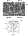
- the application of the hybrid TTI-RTM is tested on 2007 TTI data from BP.
- the image in FIG. 4A illustrates the results of conventional two-way TTI-RTM.
- the image in FIG. 4B illustrates the hybrid TTI-RTM as a result of the method 100 in FIG. 1 .
- the conventional two-way TTI-RTM image in FIG. 4A accurately illustrates a salt boundary, noise appears on the top of the image and an image ghost appears within the circle 402a.
- the noise at the top of the image in FIG. 4B weakens and the image ghost within the circle 402b beside a salt boundary is significantly reduced.
- Hybrid TTI-RTM thus, will handle rugged topography and complex near surface layers by wave equation datuming.
- Conventional two-way TTI-RTM cannot handle topography or must apply vertical static shift to the pre-stack shot gather.
- Wave equation datuming is therefore, more accurate than applying a vertical static shift, especially for areas where the velocity contrast between the near surface and the substratum is not large.
- Hybrid TTI-WEM will also generate better results than applying a vertical static shift.
- the present invention may be implemented through a computer-executable program of instructions, such as program modules, generally referred to as software applications or application programs executed by a computer.
- the software may include, for example, routines, programs, objects, components, and data structures that perform particular tasks or implement particular abstract data types.
- the software forms an interface to allow a computer to react according to a source of input.
- SeisSpaceTM which is a commercial software application marketed by Landmark Graphics Corporation, may be used as an interface application to implement the present invention.
- the software may also cooperate with other code segments to initiate a variety of tasks in response to data received in conjunction with the source of the received data.
- the software may be stored and/or carried on any variety of memory media such as CD-ROM, magnetic disk, bubble memory and semiconductor memory (e.g ., various types of RAM or ROM). Furthermore, the software and its results may be transmitted over a variety of carrier media such as optical fiber, metallic wire, free space and/or through any of a variety of networks such as the Internet.
- memory media such as CD-ROM, magnetic disk, bubble memory and semiconductor memory (e.g ., various types of RAM or ROM).
- the software and its results may be transmitted over a variety of carrier media such as optical fiber, metallic wire, free space and/or through any of a variety of networks such as the Internet.
- the invention may be practiced with a variety of computer-system configurations, including hand-held devices, multiprocessor systems, microprocessor-based or programmable-consumer electronics, minicomputers, mainframe computers, and the like. Any number of computer-systems and computer networks are acceptable for use with the present invention.
- the invention may be practiced in distributed-computing environments where tasks are performed by remote-processing devices that are linked through a communications network.
- program modules may be located in both local and remote computer-storage media including memory storage devices.
- the present invention may therefore, be implemented in connection with various hardware, software or a combination thereof, in a computer system or other processing system.
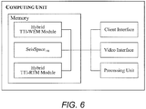
- the system includes a computing unit, sometimes referred to as a computing system, which contains memory, application programs, a client interface, a video interface and a processing unit that includes a graphics processor or graphics card.
- the computing unit is only one example of a suitable computing environment and is not intended to suggest any limitation as to the scope of use or functionality of the invention.
- the memory primarily stores the application programs, which may also be described as program modules containing computer-executable instructions, executed by the computing unit for implementing the present invention described herein and illustrated in FIGS. 1-5 .
- the memory therefore, includes a hybrid TTI-WEM module and a hybrid TTI-RTM module, which enable the method illustrated and described in reference to FIG. 1 . and integrates functionality from the remaining application programs illustrated in FIG. 6 .
- the hybrid TTI-WTM module therefore, may be used to implement steps 104-110 in FIG. 1 and the hybrid TTI-RTM module may be used to implement steps 111-113 in FIG. 1 .
- the TTI-WEM module and the TTI-RTM module may be combined into a single module to implement steps 104-113 in FIG.
- the memory also includes SeisSpace,TM which may be used as an interface application to supply input data to the hybrid TTI-WEM module and the hybrid TTI-RTM module and/or display the data results from the hybrid TTI-WEM module and the hybrid TTI-RTM module.
- SeisSpaceTM may be used to implement steps 101-102b and 114-115 in FIG. 1 .
- SeisSpaceTM may be used as an interface application, other interface applications may be used, instead, or each hybrid TTI-WEM module and hybrid TTI-RTM module may be used as a stand-alone application.
- the computing unit typically includes a variety of computer readable media.
- computer readable media may comprise computer storage media and communication media.
- the computing system memory may include computer storage media in the form of volatile and/or nonvolatile memory such as a read only memory (ROM) and random access memory (RAM).
- ROM read only memory
- RAM random access memory
- a basic input/output system (BIOS) containing the basic routines that help to transfer information between elements within the computing unit, such as during start-up, is typically stored in ROM.
- the RAM typically contains data and/or program modules that are immediately accessible to, and/or presently being operated on, the processing unit.
- the computing unit includes an operating system, application programs, other program modules, and program data.
- the components shown in the memory may also be included in other removable/nonremovable, volatile/nonvolatile computer storage media or they may be implemented in the computing unit through an application program interface ("API") or cloud computing, which may reside on a separate computing unit connected through a computer system or network.
- API application program interface
- a hard disk drive may read from or write to nonremovable, nonvolatile magnetic media
- a magnetic disk drive may read from or write to a removable, nonvolatile magnetic disk
- an optical disk drive may read from or write to a removable, nonvolatile optical disk such as a CD ROM or other optical media.
- removable/non-removable, volatile/nonvolatile computer storage media that can be used in the exemplary operating environment may include, but are not limited to, magnetic tape cassettes, flash memory cards, digital versatile disks, digital video tape, solid state RAM, solid state ROM, and the like.
- the drives and their associated computer storage media discussed above provide storage of computer readable instructions, data structures, program modules and other data for the computing unit.
- a client may enter commands and information into the computing unit through the client interface, which may be input devices such as a keyboard and pointing device, commonly referred to as a mouse, trackball or touch pad. Input devices may include a microphone, joystick, satellite dish, scanner, or the like. These and other input devices are often connected to the processing unit through the client interface that is coupled to a system bus, but may be connected by other interface and bus structures, such as a parallel port or a universal serial bus (USB).
- USB universal serial bus
- a monitor or other type of display device may be connected to the system bus via an interface, such as a video interface.
- a graphical user interface may also be used with the video interface to receive instructions from the client interface and transmit instructions to the processing unit.
- computers may also include other peripheral output devices such as speakers and printer, which may be connected through an output peripheral interface.
Landscapes
- Engineering & Computer Science (AREA)
- Physics & Mathematics (AREA)
- General Physics & Mathematics (AREA)
- Remote Sensing (AREA)
- Life Sciences & Earth Sciences (AREA)
- Computer Vision & Pattern Recognition (AREA)
- Theoretical Computer Science (AREA)
- Acoustics & Sound (AREA)
- General Life Sciences & Earth Sciences (AREA)
- Geophysics (AREA)
- Geology (AREA)
- Environmental & Geological Engineering (AREA)
- Artificial Intelligence (AREA)
- Multimedia (AREA)
- Geophysics And Detection Of Objects (AREA)
- Radar Systems Or Details Thereof (AREA)
- Image Processing (AREA)
Claims (11)
- Computerimplementiertes Verfahren (100) zur Abbildung von seismischen Daten, das Folgendes umfasst:Annähern (106) von TTI-Koeffizienten unter Verwendung einer Padé-Annäherung und einer Dispersionsbeziehungsgleichung;Anwenden (107) von Hybrid-TTI-WEM auf ein Geschwindigkeitsmodell und anisotrope Parameter für ein Prestack-Shot-Gather unter Verwendung der angenäherten TTI-Koeffizienten, um einen quellenseitigen Wellenfeldausbreitungswert und einen empfängerseitigen Wellenfeldausbreitungswert in einer Frequenz-Raum-Domäne zu bestimmen;Umwandeln (109) des quellenseitigen Wellenfeldausbreitungswertes und des empfängerseitigen Wellenfeldausbreitungswertes von der Frequenz-Raum-Domäne in eine Zeit-Raum-Domäne; undAnwenden (110) einer Nullverzögerungs-Kreuzkorrelations-Bildbedingungsgleichung, um unter Verwendung des umgewandelten quellenseitigen Wellenfeldausbreitungswertes und des umgewandelten reservoirseitigen Wellenfeldausbreitungswertes ein partielles Ausgabebild zu erzeugen.
- Verfahren nach Anspruch 1, ferner umfassend:Anwenden (111) von Hybrid-TTI-RTM auf das Geschwindigkeitsmodell und die anisotropen Parameter für das Prestack-Shot-Gather unter Verwendung des umgewandelten quellenseitigen Wellenfeldausbreitungswertes und des umgewandelten empfängerseitigen Wellenfeldausbreitungswertes, um einen anderen quellenseitigen Wellenfeldausbreitungswert und einen anderen empfängerseitigen Wellenfeldausbreitungswert in der Zeit-Raum-Domäne zu bestimmen; undAnwenden (112) der Nullverzögerungs-Kreuzkorrelations-Bildbedingungsgleichung, um unter Verwendung des anderen quellenseitigen Wellenfeldausbreitungswertes und des anderen empfängerseitigen Wellenfeldausbreitungswertes ein anderes partielles Ausgabebild zu bilden.
- Verfahren nach Anspruch 2, ferner umfassend:Stapeln jedes partiellen Ausgabebildes; undAnzeigen der gestapelten partiellen Ausgabebilder.
- Verfahren nach Anspruch 1, wobei die Dispersionsbeziehungsgleichung aus einer Phasengeschwindigkeitsfunktion und einer Rotationsmatrix erzeugt wird.
- Verfahren nach Anspruch 2, ferner umfassend das Anwenden eines Phasenverschiebungsalgorithmus auf das Geschwindigkeitsmodell und die anisotropen Parameter für das Prestack-Shot-Gather vor dem Anwenden des Hybrid-TTI-WEM, um den quellenseitigen Wellenfeldausbreitungswert und den empfängerseitigen Wellenfeldausbreitungswert zu bestimmen.
- Verfahren nach Anspruch 5, ferner umfassend das Festlegen (102a) einer Migrationstiefe zwischen der Hybrid-TTI-WEM und der Hybrid-TTI-RTM.
- Verfahren nach Anspruch 6, wobei der Phasenverschiebungsalgorithmus von einer Wasseroberfläche zu einer unterirdischen Fläche, an der das Wasser auf Erde trifft, auf das Geschwindigkeitsmodell und die anisotropen Parameter angewandt wird.
- Verfahren nach Anspruch 6, wobei die Hybrid-TTI-WEM von einer Erdoberfläche oder einer unterirdischen Fläche, an der Wasser auf Erde trifft, zu der Migrationstiefe auf das Geschwindigkeitsmodell und die anisotropen Parameter angewandt wird.
- Verfahren nach Anspruch 6, wobei die Hybrid-TTI-RTM von der Migrationstiefe zu einem Ausmaß des Geschwindigkeitsmodells auf das Geschwindigkeitsmodell und die anisotropen Parameter angewandt wird.
- Verfahren nach Anspruch 2, ferner umfassend:Filtern und Glätten (113) jedes partiellen Ausgabebildes, um ein jeweiliges amplitudenkonsistentes partielles Ausgabebild zu erzeugen;Stapeln jedes amplitudenkonsistenten partiellen Ausgabebildes; undAnzeigen der gestapelten amplitudenkonsistenten partiellen Ausgabebilder.
- Nichtflüchtige Programmträgervorrichtung, die greifbar computerausführbare Anweisungen zur Abbildung von seismischen Daten enthält, wobei die Anweisungen ausführbar sind, um das Verfahren nach einem vorhergehenden Anspruch durchzuführen.
Applications Claiming Priority (1)
| Application Number | Priority Date | Filing Date | Title |
|---|---|---|---|
| PCT/US2012/051387 WO2014028030A1 (en) | 2012-08-17 | 2012-08-17 | Systems and methods for imaging seismic data |
Publications (3)
| Publication Number | Publication Date |
|---|---|
| EP2885656A1 EP2885656A1 (de) | 2015-06-24 |
| EP2885656A4 EP2885656A4 (de) | 2016-04-06 |
| EP2885656B1 true EP2885656B1 (de) | 2018-09-26 |
Family
ID=50685678
Family Applications (1)
| Application Number | Title | Priority Date | Filing Date |
|---|---|---|---|
| EP12886507.8A Not-in-force EP2885656B1 (de) | 2012-08-17 | 2012-08-17 | Verfahren zur abbildung von seismischen daten |
Country Status (6)
| Country | Link |
|---|---|
| US (1) | US9536143B2 (de) |
| EP (1) | EP2885656B1 (de) |
| AU (1) | AU2012387658B2 (de) |
| CA (1) | CA2881807C (de) |
| RU (1) | RU2596182C1 (de) |
| WO (1) | WO2014028030A1 (de) |
Families Citing this family (24)
| Publication number | Priority date | Publication date | Assignee | Title |
|---|---|---|---|---|
| WO2011141440A1 (en) * | 2010-05-12 | 2011-11-17 | Shell Internationale Research Maatschappij B.V. | Seismic p-wave modelling in an inhomogeneous transversely isotropic medium with a tilted symmetry axis |
| WO2016008100A1 (zh) * | 2014-07-15 | 2016-01-21 | 杨顺伟 | 一种三维地震各向异性介质逆时偏移成像方法及装置 |
| CN104635267B (zh) * | 2015-02-10 | 2015-08-19 | 中国海洋大学 | 一种地震波分阶逆时偏移加权叠加成像方法 |
| US10302741B2 (en) * | 2015-04-02 | 2019-05-28 | Texas Instruments Incorporated | Method and apparatus for live-object detection |
| CN105425287B (zh) * | 2015-11-09 | 2017-10-27 | 中国地质大学(北京) | 地震波的叠前分离方法 |
| CN105652321B (zh) * | 2015-12-30 | 2016-10-12 | 中国石油大学(华东) | 一种粘声各向异性最小二乘逆时偏移成像方法 |
| US10535168B2 (en) * | 2016-03-02 | 2020-01-14 | Schlumberger Technology Corporation | Image enhancement using seismic partition images |
| CN106199717B (zh) * | 2016-07-08 | 2018-07-13 | 中国石油天然气集团公司 | 方位各向异性剩余时差校正方法及装置 |
| WO2018118733A2 (en) * | 2016-12-19 | 2018-06-28 | Schlumberger Technology Corporation | Cloud framework system |
| US10295685B2 (en) | 2017-04-06 | 2019-05-21 | Saudi Arabian Oil Company | Generating common image gather using wave-field separation |
| US11016212B2 (en) | 2017-04-11 | 2021-05-25 | Saudi Arabian Oil Company | Compressing seismic wavefields in three-dimensional reverse time migration |
| CN107193043B (zh) * | 2017-05-15 | 2019-03-29 | 中国石油大学(华东) | 一种起伏地表的地下构造成像方法 |
| US10557954B2 (en) * | 2017-06-12 | 2020-02-11 | Saudi Arabian Oil Company | Modeling angle domain common image gathers from reverse time migration |
| CN107179549B (zh) * | 2017-07-11 | 2019-02-26 | 中海石油(中国)有限公司 | 一种时间域声波方程显式有限差分地震响应模拟方法 |
| US10788597B2 (en) | 2017-12-11 | 2020-09-29 | Saudi Arabian Oil Company | Generating a reflectivity model of subsurface structures |
| US11275190B2 (en) | 2018-05-16 | 2022-03-15 | Saudi Arabian Oil Company | Generating diffraction images based on wave equations |
| CN108646294B (zh) * | 2018-06-29 | 2019-09-06 | 中海石油(中国)有限公司 | 一种复杂断裂系统下深水浊积砂岩储层高精度反演方法 |
| US11681043B2 (en) * | 2019-09-03 | 2023-06-20 | Saudi Arabian Oil Company | Diffraction imaging using pseudo dip-angle gather |
| US11313988B2 (en) | 2019-12-13 | 2022-04-26 | Saudi Arabian Oil Company | Identifying geologic features in a subterranean formation using seismic diffraction imaging |
| US11402529B2 (en) | 2020-01-09 | 2022-08-02 | Saudi Arabian Oil Company | Identifying geologic features in a subterranean formation using seismic diffraction and refraction imaging |
| US11467303B2 (en) | 2020-03-09 | 2022-10-11 | Saudi Arabian Oil Company | Identifying geologic features in a subterranean formation using a post-stack seismic diffraction imaging condition |
| US11320557B2 (en) | 2020-03-30 | 2022-05-03 | Saudi Arabian Oil Company | Post-stack time domain image with broadened spectrum |
| US11656378B2 (en) | 2020-06-08 | 2023-05-23 | Saudi Arabian Oil Company | Seismic imaging by visco-acoustic reverse time migration |
| CN114151066B (zh) * | 2021-10-09 | 2023-04-25 | 电子科技大学 | 一种超声Lamb波测井井壁声学界面逆时偏移成像方法 |
Family Cites Families (28)
| Publication number | Priority date | Publication date | Assignee | Title |
|---|---|---|---|---|
| US4809235A (en) * | 1987-09-28 | 1989-02-28 | Western Atlas International, Inc. | Method for removing doppler phase dispersion from seismic data |
| US5392213A (en) * | 1992-10-23 | 1995-02-21 | Exxon Production Research Company | Filter for removal of coherent noise from seismic data |
| US5933789A (en) * | 1996-11-12 | 1999-08-03 | Atlantic Richfield Company | Method and system for applying dispersive normal moveout corrections to seismic survey signals |
| US5999488A (en) | 1998-04-27 | 1999-12-07 | Phillips Petroleum Company | Method and apparatus for migration by finite differences |
| DE19841262C2 (de) | 1998-09-09 | 2000-12-28 | Ibs Integrierte Business Syste | Elektronische Schaltung zur Aufzeichnung von geografischen Positionsdaten auf dem Tonkanal eines Camcorders |
| US6021094A (en) | 1998-12-03 | 2000-02-01 | Sandia Corporation | Method of migrating seismic records |
| US6687659B1 (en) | 2000-03-24 | 2004-02-03 | Conocophillips Company | Method and apparatus for absorbing boundary conditions in numerical finite-difference acoustic applications |
| AU2001251019A1 (en) | 2000-03-27 | 2001-10-08 | Peter J. Ortoleva | Method for simulation of enhanced fracture detection in sedimentary basins |
| WO2002047011A1 (en) | 2000-12-08 | 2002-06-13 | Ortoleva Peter J | Methods for modeling multi-dimensional domains using information theory to resolve gaps in data and in theories |
| US6519532B2 (en) | 2001-01-31 | 2003-02-11 | Phillips Petroleum Company | Method and apparatus for 3D depth migration |
| US6748330B2 (en) * | 2002-04-10 | 2004-06-08 | Schlumberger Technology Corporation | Method and apparatus for anisotropic vector plane wave decomposition for 3D vertical seismic profile data |
| US6819628B2 (en) * | 2003-04-07 | 2004-11-16 | Paradigm Geophysical (Luxembourg) S.A.R.L. | Wave migration by a krylov space expansion of the square root exponent operator, for use in seismic imaging |
| US20070162249A1 (en) | 2006-01-06 | 2007-07-12 | Min Lou | Traveltime calculation in three dimensional transversely isotropic (3D TTI) media by the fast marching method |
| US7400553B1 (en) | 2006-11-30 | 2008-07-15 | Shengwen Jin | One-return wave equation migration |
| WO2008087505A2 (en) | 2007-01-20 | 2008-07-24 | Spectraseis Ag | Time reverse reservoir localization |
| US20080319726A1 (en) * | 2007-06-19 | 2008-12-25 | Schlumberger Technology Corporation | System and method for performing oilfield simulation operations |
| US8194498B2 (en) * | 2008-01-18 | 2012-06-05 | Westerngeco L.L.C. | Using a wave propagator for transversely isotropic media |
| US8116168B1 (en) * | 2008-06-18 | 2012-02-14 | Halliburton Energy Services, Inc. | Hybrid one-way and full-way wave equation migration |
| EA201170261A1 (ru) | 2008-07-30 | 2011-08-30 | Шеврон Ю.Эс.Эй. Инк. | Способ распространения псевдоакустической квази-р волны в анизотропной среде |
| EP2184620B1 (de) * | 2008-08-26 | 2011-10-26 | PGS Geophysical AS | Finite-Differenzen-Fouriermigration für dreidimensionale geneigte transversal-isotrope Medien |
| US20100054082A1 (en) | 2008-08-29 | 2010-03-04 | Acceleware Corp. | Reverse-time depth migration with reduced memory requirements |
| US8296069B2 (en) | 2008-10-06 | 2012-10-23 | Bp Corporation North America Inc. | Pseudo-analytical method for the solution of wave equations |
| US20100118651A1 (en) | 2008-11-10 | 2010-05-13 | Chevron U.S.A. Inc. | Method for generation of images related to a subsurface region of interest |
| US20100135115A1 (en) * | 2008-12-03 | 2010-06-03 | Chevron U.S.A. Inc. | Multiple anisotropic parameter inversion for a tti earth model |
| MX2011003850A (es) | 2009-01-20 | 2011-07-21 | Spectraseis Ag | Estimado de señal de dominio de imagen a interferencia. |
| MX2011003851A (es) | 2009-01-20 | 2011-07-21 | Spectraseis Ag | Operadores para procesamiento de imagen con inversion de tiempo para ubicacion de fuente. |
| CN102597808B (zh) * | 2009-11-02 | 2016-08-03 | 界标制图有限公司 | 采用倾斜的横向各向同性的3d逆向时间偏移的地震成像系统与方法 |
| WO2011141440A1 (en) * | 2010-05-12 | 2011-11-17 | Shell Internationale Research Maatschappij B.V. | Seismic p-wave modelling in an inhomogeneous transversely isotropic medium with a tilted symmetry axis |
-
2012
- 2012-08-17 AU AU2012387658A patent/AU2012387658B2/en not_active Ceased
- 2012-08-17 WO PCT/US2012/051387 patent/WO2014028030A1/en not_active Ceased
- 2012-08-17 CA CA2881807A patent/CA2881807C/en not_active Expired - Fee Related
- 2012-08-17 RU RU2015104566/28A patent/RU2596182C1/ru not_active IP Right Cessation
- 2012-08-17 US US14/422,096 patent/US9536143B2/en not_active Expired - Fee Related
- 2012-08-17 EP EP12886507.8A patent/EP2885656B1/de not_active Not-in-force
Non-Patent Citations (1)
| Title |
|---|
| None * |
Also Published As
| Publication number | Publication date |
|---|---|
| US9536143B2 (en) | 2017-01-03 |
| EP2885656A1 (de) | 2015-06-24 |
| AU2012387658B2 (en) | 2016-06-23 |
| US20150235081A1 (en) | 2015-08-20 |
| RU2596182C1 (ru) | 2016-08-27 |
| CA2881807A1 (en) | 2014-02-20 |
| AU2012387658A1 (en) | 2015-02-26 |
| WO2014028030A1 (en) | 2014-02-20 |
| CA2881807C (en) | 2017-10-17 |
| EP2885656A4 (de) | 2016-04-06 |
Similar Documents
| Publication | Publication Date | Title |
|---|---|---|
| EP2885656B1 (de) | Verfahren zur abbildung von seismischen daten | |
| US10620331B2 (en) | Reverse time migration in anisotropic media with stable attenuation compensation | |
| Nakata et al. | Shear wave imaging from traffic noise using seismic interferometry by cross-coherence | |
| EP3073296B1 (de) | Vollwellenforminversionsverfahren zur verarbeitung von seismischen daten mit amplitudenerhaltender umkehrzeitmigration | |
| Oh et al. | 3D elastic full-waveform inversion using P-wave excitation amplitude: Application to ocean bottom cable field data | |
| US10228476B2 (en) | Method for survey data processing compensating for visco-acoustic effects in tilted transverse isotropy reverse time migration | |
| EP3028071B1 (de) | Verfahren und vorrichtung zur erzeugung und anwendung von anisotropischen elastischen parametern in horizontalen transversal-isotropen (hti-)medien | |
| US11561312B2 (en) | Mapping near-surface heterogeneities in a subterranean formation | |
| CN103926619B (zh) | 一种三维vsp数据的逆时偏移方法 | |
| EP2755059B1 (de) | Verarbeitung seismischer Daten einschließlich datenabhängiger, oberflächenkonsistenter Korrektur | |
| US20170184748A1 (en) | A method and a computing system for seismic imaging a geological formation | |
| CN103635831A (zh) | 在3d各向异性介质中的基于敏感度内核的偏移速度分析 | |
| US9465125B2 (en) | Seismic data processing including compensating for source and receiver ghost effects in reverse time migration | |
| Wu et al. | Least-squares reverse-time migration with sparsity constraints | |
| CN102540253B (zh) | 一种陡倾角地层及裂缝地震偏移方法和装置 | |
| Takam Takougang et al. | Application of waveform tomography to marine seismic reflection data from the Queen Charlotte Basin of western Canada | |
| Yan et al. | The new angle-domain imaging condition for elastic RTM | |
| Liu et al. | Joint velocity building and imaging of compressional and shear waves: application to gas cloud imaging | |
| Alqatari et al. | Near-borehole imaging using full-waveform sonic data | |
| Jing et al. | Benefits and applications of elastic reverse time migration in salt-related imaging | |
| Dai et al. | Imaging beneath gas clouds using 3D prestack Kirchhoff time migration of PS-converted waves—A case study from the North Sea | |
| Lin et al. | Improving the image quality of high-angle interfaces and subsalt sediments using high-order scattered seismic waves | |
| Rusmanugroho et al. | Pre-Stack Depth Migration of High Resolution Distributed Acoustic Sensing VSP | |
| Wang et al. | L1-Norm Multi-Constraint Inversion Based on N-ADMM with an adaptive penalty | |
| Yan et al. | Seismic characterization of fractures by imaging scattered waves in the angle domain |
Legal Events
| Date | Code | Title | Description |
|---|---|---|---|
| PUAI | Public reference made under article 153(3) epc to a published international application that has entered the european phase |
Free format text: ORIGINAL CODE: 0009012 |
|
| 17P | Request for examination filed |
Effective date: 20150210 |
|
| AK | Designated contracting states |
Kind code of ref document: A1 Designated state(s): AL AT BE BG CH CY CZ DE DK EE ES FI FR GB GR HR HU IE IS IT LI LT LU LV MC MK MT NL NO PL PT RO RS SE SI SK SM TR |
|
| AX | Request for extension of the european patent |
Extension state: BA ME |
|
| DAX | Request for extension of the european patent (deleted) | ||
| RA4 | Supplementary search report drawn up and despatched (corrected) |
Effective date: 20160303 |
|
| RIC1 | Information provided on ipc code assigned before grant |
Ipc: G01V 1/28 20060101AFI20160226BHEP |
|
| REG | Reference to a national code |
Ref country code: DE Ref legal event code: R079 Ref document number: 602012051640 Country of ref document: DE Free format text: PREVIOUS MAIN CLASS: G01V0001000000 Ipc: G01V0001280000 |
|
| GRAP | Despatch of communication of intention to grant a patent |
Free format text: ORIGINAL CODE: EPIDOSNIGR1 |
|
| STAA | Information on the status of an ep patent application or granted ep patent |
Free format text: STATUS: GRANT OF PATENT IS INTENDED |
|
| RIC1 | Information provided on ipc code assigned before grant |
Ipc: G01V 1/28 20060101AFI20180321BHEP |
|
| INTG | Intention to grant announced |
Effective date: 20180411 |
|
| GRAS | Grant fee paid |
Free format text: ORIGINAL CODE: EPIDOSNIGR3 |
|
| GRAA | (expected) grant |
Free format text: ORIGINAL CODE: 0009210 |
|
| STAA | Information on the status of an ep patent application or granted ep patent |
Free format text: STATUS: THE PATENT HAS BEEN GRANTED |
|
| AK | Designated contracting states |
Kind code of ref document: B1 Designated state(s): AL AT BE BG CH CY CZ DE DK EE ES FI FR GB GR HR HU IE IS IT LI LT LU LV MC MK MT NL NO PL PT RO RS SE SI SK SM TR |
|
| REG | Reference to a national code |
Ref country code: GB Ref legal event code: FG4D |
|
| REG | Reference to a national code |
Ref country code: CH Ref legal event code: EP |
|
| REG | Reference to a national code |
Ref country code: AT Ref legal event code: REF Ref document number: 1046681 Country of ref document: AT Kind code of ref document: T Effective date: 20181015 |
|
| REG | Reference to a national code |
Ref country code: IE Ref legal event code: FG4D |
|
| REG | Reference to a national code |
Ref country code: DE Ref legal event code: R096 Ref document number: 602012051640 Country of ref document: DE |
|
| REG | Reference to a national code |
Ref country code: NO Ref legal event code: T2 Effective date: 20180926 |
|
| REG | Reference to a national code |
Ref country code: NL Ref legal event code: MP Effective date: 20180926 |
|
| PG25 | Lapsed in a contracting state [announced via postgrant information from national office to epo] |
Ref country code: LT Free format text: LAPSE BECAUSE OF FAILURE TO SUBMIT A TRANSLATION OF THE DESCRIPTION OR TO PAY THE FEE WITHIN THE PRESCRIBED TIME-LIMIT Effective date: 20180926 Ref country code: RS Free format text: LAPSE BECAUSE OF FAILURE TO SUBMIT A TRANSLATION OF THE DESCRIPTION OR TO PAY THE FEE WITHIN THE PRESCRIBED TIME-LIMIT Effective date: 20180926 Ref country code: BG Free format text: LAPSE BECAUSE OF FAILURE TO SUBMIT A TRANSLATION OF THE DESCRIPTION OR TO PAY THE FEE WITHIN THE PRESCRIBED TIME-LIMIT Effective date: 20181226 Ref country code: SE Free format text: LAPSE BECAUSE OF FAILURE TO SUBMIT A TRANSLATION OF THE DESCRIPTION OR TO PAY THE FEE WITHIN THE PRESCRIBED TIME-LIMIT Effective date: 20180926 Ref country code: GR Free format text: LAPSE BECAUSE OF FAILURE TO SUBMIT A TRANSLATION OF THE DESCRIPTION OR TO PAY THE FEE WITHIN THE PRESCRIBED TIME-LIMIT Effective date: 20181227 Ref country code: FI Free format text: LAPSE BECAUSE OF FAILURE TO SUBMIT A TRANSLATION OF THE DESCRIPTION OR TO PAY THE FEE WITHIN THE PRESCRIBED TIME-LIMIT Effective date: 20180926 |
|
| REG | Reference to a national code |
Ref country code: LT Ref legal event code: MG4D |
|
| PG25 | Lapsed in a contracting state [announced via postgrant information from national office to epo] |
Ref country code: AL Free format text: LAPSE BECAUSE OF FAILURE TO SUBMIT A TRANSLATION OF THE DESCRIPTION OR TO PAY THE FEE WITHIN THE PRESCRIBED TIME-LIMIT Effective date: 20180926 Ref country code: LV Free format text: LAPSE BECAUSE OF FAILURE TO SUBMIT A TRANSLATION OF THE DESCRIPTION OR TO PAY THE FEE WITHIN THE PRESCRIBED TIME-LIMIT Effective date: 20180926 Ref country code: HR Free format text: LAPSE BECAUSE OF FAILURE TO SUBMIT A TRANSLATION OF THE DESCRIPTION OR TO PAY THE FEE WITHIN THE PRESCRIBED TIME-LIMIT Effective date: 20180926 |
|
| REG | Reference to a national code |
Ref country code: AT Ref legal event code: MK05 Ref document number: 1046681 Country of ref document: AT Kind code of ref document: T Effective date: 20180926 |
|
| PG25 | Lapsed in a contracting state [announced via postgrant information from national office to epo] |
Ref country code: CZ Free format text: LAPSE BECAUSE OF FAILURE TO SUBMIT A TRANSLATION OF THE DESCRIPTION OR TO PAY THE FEE WITHIN THE PRESCRIBED TIME-LIMIT Effective date: 20180926 Ref country code: RO Free format text: LAPSE BECAUSE OF FAILURE TO SUBMIT A TRANSLATION OF THE DESCRIPTION OR TO PAY THE FEE WITHIN THE PRESCRIBED TIME-LIMIT Effective date: 20180926 Ref country code: IT Free format text: LAPSE BECAUSE OF FAILURE TO SUBMIT A TRANSLATION OF THE DESCRIPTION OR TO PAY THE FEE WITHIN THE PRESCRIBED TIME-LIMIT Effective date: 20180926 Ref country code: NL Free format text: LAPSE BECAUSE OF FAILURE TO SUBMIT A TRANSLATION OF THE DESCRIPTION OR TO PAY THE FEE WITHIN THE PRESCRIBED TIME-LIMIT Effective date: 20180926 Ref country code: PL Free format text: LAPSE BECAUSE OF FAILURE TO SUBMIT A TRANSLATION OF THE DESCRIPTION OR TO PAY THE FEE WITHIN THE PRESCRIBED TIME-LIMIT Effective date: 20180926 Ref country code: IS Free format text: LAPSE BECAUSE OF FAILURE TO SUBMIT A TRANSLATION OF THE DESCRIPTION OR TO PAY THE FEE WITHIN THE PRESCRIBED TIME-LIMIT Effective date: 20190126 Ref country code: EE Free format text: LAPSE BECAUSE OF FAILURE TO SUBMIT A TRANSLATION OF THE DESCRIPTION OR TO PAY THE FEE WITHIN THE PRESCRIBED TIME-LIMIT Effective date: 20180926 Ref country code: AT Free format text: LAPSE BECAUSE OF FAILURE TO SUBMIT A TRANSLATION OF THE DESCRIPTION OR TO PAY THE FEE WITHIN THE PRESCRIBED TIME-LIMIT Effective date: 20180926 |
|
| PG25 | Lapsed in a contracting state [announced via postgrant information from national office to epo] |
Ref country code: SK Free format text: LAPSE BECAUSE OF FAILURE TO SUBMIT A TRANSLATION OF THE DESCRIPTION OR TO PAY THE FEE WITHIN THE PRESCRIBED TIME-LIMIT Effective date: 20180926 Ref country code: SM Free format text: LAPSE BECAUSE OF FAILURE TO SUBMIT A TRANSLATION OF THE DESCRIPTION OR TO PAY THE FEE WITHIN THE PRESCRIBED TIME-LIMIT Effective date: 20180926 Ref country code: PT Free format text: LAPSE BECAUSE OF FAILURE TO SUBMIT A TRANSLATION OF THE DESCRIPTION OR TO PAY THE FEE WITHIN THE PRESCRIBED TIME-LIMIT Effective date: 20190126 |
|
| REG | Reference to a national code |
Ref country code: DE Ref legal event code: R097 Ref document number: 602012051640 Country of ref document: DE |
|
| PG25 | Lapsed in a contracting state [announced via postgrant information from national office to epo] |
Ref country code: ES Free format text: LAPSE BECAUSE OF FAILURE TO SUBMIT A TRANSLATION OF THE DESCRIPTION OR TO PAY THE FEE WITHIN THE PRESCRIBED TIME-LIMIT Effective date: 20180926 Ref country code: DK Free format text: LAPSE BECAUSE OF FAILURE TO SUBMIT A TRANSLATION OF THE DESCRIPTION OR TO PAY THE FEE WITHIN THE PRESCRIBED TIME-LIMIT Effective date: 20180926 |
|
| PLBE | No opposition filed within time limit |
Free format text: ORIGINAL CODE: 0009261 |
|
| STAA | Information on the status of an ep patent application or granted ep patent |
Free format text: STATUS: NO OPPOSITION FILED WITHIN TIME LIMIT |
|
| 26N | No opposition filed |
Effective date: 20190627 |
|
| PG25 | Lapsed in a contracting state [announced via postgrant information from national office to epo] |
Ref country code: SI Free format text: LAPSE BECAUSE OF FAILURE TO SUBMIT A TRANSLATION OF THE DESCRIPTION OR TO PAY THE FEE WITHIN THE PRESCRIBED TIME-LIMIT Effective date: 20180926 |
|
| PGFP | Annual fee paid to national office [announced via postgrant information from national office to epo] |
Ref country code: GB Payment date: 20190610 Year of fee payment: 8 Ref country code: FR Payment date: 20190830 Year of fee payment: 8 Ref country code: NO Payment date: 20190726 Year of fee payment: 8 |
|
| REG | Reference to a national code |
Ref country code: DE Ref legal event code: R119 Ref document number: 602012051640 Country of ref document: DE |
|
| PG25 | Lapsed in a contracting state [announced via postgrant information from national office to epo] |
Ref country code: TR Free format text: LAPSE BECAUSE OF FAILURE TO SUBMIT A TRANSLATION OF THE DESCRIPTION OR TO PAY THE FEE WITHIN THE PRESCRIBED TIME-LIMIT Effective date: 20180926 |
|
| PG25 | Lapsed in a contracting state [announced via postgrant information from national office to epo] |
Ref country code: CH Free format text: LAPSE BECAUSE OF NON-PAYMENT OF DUE FEES Effective date: 20190831 Ref country code: MC Free format text: LAPSE BECAUSE OF FAILURE TO SUBMIT A TRANSLATION OF THE DESCRIPTION OR TO PAY THE FEE WITHIN THE PRESCRIBED TIME-LIMIT Effective date: 20180926 Ref country code: LU Free format text: LAPSE BECAUSE OF NON-PAYMENT OF DUE FEES Effective date: 20190817 Ref country code: LI Free format text: LAPSE BECAUSE OF NON-PAYMENT OF DUE FEES Effective date: 20190831 |
|
| REG | Reference to a national code |
Ref country code: BE Ref legal event code: MM Effective date: 20190831 |
|
| PG25 | Lapsed in a contracting state [announced via postgrant information from national office to epo] |
Ref country code: DE Free format text: LAPSE BECAUSE OF NON-PAYMENT OF DUE FEES Effective date: 20200303 Ref country code: IE Free format text: LAPSE BECAUSE OF NON-PAYMENT OF DUE FEES Effective date: 20190817 |
|
| PG25 | Lapsed in a contracting state [announced via postgrant information from national office to epo] |
Ref country code: BE Free format text: LAPSE BECAUSE OF NON-PAYMENT OF DUE FEES Effective date: 20190831 |
|
| REG | Reference to a national code |
Ref country code: NO Ref legal event code: MMEP |
|
| GBPC | Gb: european patent ceased through non-payment of renewal fee |
Effective date: 20200817 |
|
| PG25 | Lapsed in a contracting state [announced via postgrant information from national office to epo] |
Ref country code: NO Free format text: LAPSE BECAUSE OF NON-PAYMENT OF DUE FEES Effective date: 20200831 |
|
| PG25 | Lapsed in a contracting state [announced via postgrant information from national office to epo] |
Ref country code: CY Free format text: LAPSE BECAUSE OF FAILURE TO SUBMIT A TRANSLATION OF THE DESCRIPTION OR TO PAY THE FEE WITHIN THE PRESCRIBED TIME-LIMIT Effective date: 20180926 |
|
| PG25 | Lapsed in a contracting state [announced via postgrant information from national office to epo] |
Ref country code: MT Free format text: LAPSE BECAUSE OF FAILURE TO SUBMIT A TRANSLATION OF THE DESCRIPTION OR TO PAY THE FEE WITHIN THE PRESCRIBED TIME-LIMIT Effective date: 20180926 Ref country code: HU Free format text: LAPSE BECAUSE OF FAILURE TO SUBMIT A TRANSLATION OF THE DESCRIPTION OR TO PAY THE FEE WITHIN THE PRESCRIBED TIME-LIMIT; INVALID AB INITIO Effective date: 20120817 Ref country code: FR Free format text: LAPSE BECAUSE OF NON-PAYMENT OF DUE FEES Effective date: 20200831 |
|
| PG25 | Lapsed in a contracting state [announced via postgrant information from national office to epo] |
Ref country code: GB Free format text: LAPSE BECAUSE OF NON-PAYMENT OF DUE FEES Effective date: 20200817 |
|
| PG25 | Lapsed in a contracting state [announced via postgrant information from national office to epo] |
Ref country code: MK Free format text: LAPSE BECAUSE OF FAILURE TO SUBMIT A TRANSLATION OF THE DESCRIPTION OR TO PAY THE FEE WITHIN THE PRESCRIBED TIME-LIMIT Effective date: 20180926 |