EP2885566B1 - Aufnahme für einen vorratsbehälter, anordnung solcher aufnahmen, fahrzeugbehandlungsanlage und vorratsbehälter - Google Patents
Aufnahme für einen vorratsbehälter, anordnung solcher aufnahmen, fahrzeugbehandlungsanlage und vorratsbehälter Download PDFInfo
- Publication number
- EP2885566B1 EP2885566B1 EP13753145.5A EP13753145A EP2885566B1 EP 2885566 B1 EP2885566 B1 EP 2885566B1 EP 13753145 A EP13753145 A EP 13753145A EP 2885566 B1 EP2885566 B1 EP 2885566B1
- Authority
- EP
- European Patent Office
- Prior art keywords
- coupling
- holder
- actuating
- holders
- supply container
- Prior art date
- Legal status (The legal status is an assumption and is not a legal conclusion. Google has not performed a legal analysis and makes no representation as to the accuracy of the status listed.)
- Not-in-force
Links
- 238000003860 storage Methods 0.000 title description 13
- 230000008878 coupling Effects 0.000 claims description 79
- 238000010168 coupling process Methods 0.000 claims description 79
- 238000005859 coupling reaction Methods 0.000 claims description 79
- 239000000654 additive Substances 0.000 claims description 13
- 238000003780 insertion Methods 0.000 claims description 11
- 230000037431 insertion Effects 0.000 claims description 11
- 238000009434 installation Methods 0.000 claims description 5
- 230000013011 mating Effects 0.000 claims 4
- 230000006835 compression Effects 0.000 description 11
- 238000007906 compression Methods 0.000 description 11
- 238000007789 sealing Methods 0.000 description 10
- 239000007788 liquid Substances 0.000 description 8
- 238000005406 washing Methods 0.000 description 7
- XLYOFNOQVPJJNP-UHFFFAOYSA-N water Substances O XLYOFNOQVPJJNP-UHFFFAOYSA-N 0.000 description 4
- 239000001993 wax Substances 0.000 description 4
- 230000000996 additive effect Effects 0.000 description 3
- 230000006378 damage Effects 0.000 description 3
- 230000002349 favourable effect Effects 0.000 description 3
- 239000002453 shampoo Substances 0.000 description 3
- 238000009423 ventilation Methods 0.000 description 3
- 238000013022 venting Methods 0.000 description 3
- 241000238631 Hexapoda Species 0.000 description 2
- 208000027418 Wounds and injury Diseases 0.000 description 2
- 238000004140 cleaning Methods 0.000 description 2
- 238000013461 design Methods 0.000 description 2
- 238000001035 drying Methods 0.000 description 2
- -1 drying aids Substances 0.000 description 2
- 239000004088 foaming agent Substances 0.000 description 2
- 208000014674 injury Diseases 0.000 description 2
- 239000000344 soap Substances 0.000 description 2
- 238000005273 aeration Methods 0.000 description 1
- 239000007640 basal medium Substances 0.000 description 1
- 230000005540 biological transmission Effects 0.000 description 1
- 230000001680 brushing effect Effects 0.000 description 1
- 150000001875 compounds Chemical class 0.000 description 1
- 238000010276 construction Methods 0.000 description 1
- 238000011161 development Methods 0.000 description 1
- 238000006073 displacement reaction Methods 0.000 description 1
- 239000012530 fluid Substances 0.000 description 1
- 238000004519 manufacturing process Methods 0.000 description 1
- 239000002609 medium Substances 0.000 description 1
- 238000000034 method Methods 0.000 description 1
- 238000005498 polishing Methods 0.000 description 1
- 239000012254 powdered material Substances 0.000 description 1
- 238000000926 separation method Methods 0.000 description 1
Images

Classifications
-
- F—MECHANICAL ENGINEERING; LIGHTING; HEATING; WEAPONS; BLASTING
- F16—ENGINEERING ELEMENTS AND UNITS; GENERAL MEASURES FOR PRODUCING AND MAINTAINING EFFECTIVE FUNCTIONING OF MACHINES OR INSTALLATIONS; THERMAL INSULATION IN GENERAL
- F16L—PIPES; JOINTS OR FITTINGS FOR PIPES; SUPPORTS FOR PIPES, CABLES OR PROTECTIVE TUBING; MEANS FOR THERMAL INSULATION IN GENERAL
- F16L37/00—Couplings of the quick-acting type
- F16L37/08—Couplings of the quick-acting type in which the connection between abutting or axially overlapping ends is maintained by locking members
- F16L37/084—Couplings of the quick-acting type in which the connection between abutting or axially overlapping ends is maintained by locking members combined with automatic locking
- F16L37/086—Couplings of the quick-acting type in which the connection between abutting or axially overlapping ends is maintained by locking members combined with automatic locking by means of latching members pushed radially by spring-like elements
-
- F—MECHANICAL ENGINEERING; LIGHTING; HEATING; WEAPONS; BLASTING
- F16—ENGINEERING ELEMENTS AND UNITS; GENERAL MEASURES FOR PRODUCING AND MAINTAINING EFFECTIVE FUNCTIONING OF MACHINES OR INSTALLATIONS; THERMAL INSULATION IN GENERAL
- F16L—PIPES; JOINTS OR FITTINGS FOR PIPES; SUPPORTS FOR PIPES, CABLES OR PROTECTIVE TUBING; MEANS FOR THERMAL INSULATION IN GENERAL
- F16L37/00—Couplings of the quick-acting type
- F16L37/28—Couplings of the quick-acting type with fluid cut-off means
- F16L37/30—Couplings of the quick-acting type with fluid cut-off means with fluid cut-off means in each of two pipe-end fittings
- F16L37/32—Couplings of the quick-acting type with fluid cut-off means with fluid cut-off means in each of two pipe-end fittings at least one of two lift valves being opened automatically when the coupling is applied
- F16L37/34—Couplings of the quick-acting type with fluid cut-off means with fluid cut-off means in each of two pipe-end fittings at least one of two lift valves being opened automatically when the coupling is applied at least one of the lift valves being of the sleeve type, i.e. a sleeve being telescoped over an inner cylindrical wall
-
- B—PERFORMING OPERATIONS; TRANSPORTING
- B60—VEHICLES IN GENERAL
- B60S—SERVICING, CLEANING, REPAIRING, SUPPORTING, LIFTING, OR MANOEUVRING OF VEHICLES, NOT OTHERWISE PROVIDED FOR
- B60S3/00—Vehicle cleaning apparatus not integral with vehicles
- B60S3/04—Vehicle cleaning apparatus not integral with vehicles for exteriors of land vehicles
Definitions
- the invention relates to a receptacle for a reservoir for additives in vehicle treatment plants for automatically holding the reservoir after insertion of the reservoir into the receptacle, an arrangement of such receptacles, a vehicle treatment plant and a recording with a reservoir.
- Such a reservoir discloses the DE 10 2007 017 615 A1 in the form of a cartridge for insertion into a receiving device of a vehicle treatment device.
- the cartridges are often laborious to exchange and difficult to handle.
- the US Pat. No. 6,158,486 discloses a receptacle for a reservoir with a coupling arranged at the inlet of the receptacle.
- a releasable snap connection formed by lips holds the container against a spring in the receptacle. This prevents that the container is pushed out of the receptacle within a predetermined by the snap connection force range. When the force range is exceeded However, the reservoir can be easily pulled out of the recording, a secure locking of the coupling between recording and container does not take place.
- the US 2002/093194 A1 discloses a quick coupling for connecting two tubes with a locking device, which allows a lock of the quick coupling via a push button.
- the US Pat. No. 6,382,593 B1 discloses a liquid coupling for dispensing liquids, which is provided for connection within a liquid source arranged inlets with a liquid receiving element.
- the fluid coupling comprises a housing defining a central passage between the front and rear openings and a first flow passage between the rear and a side openings.
- a lever drive is rotatably mounted on the housing to open or close the first flow passage.
- the US 2007/187 433 A1 discloses a metering and dispensing closure for a container in which two rotatable discs rotate in conjunction with a stationary cap member to allow accurate metering and dispensing of a powdered material.
- the DE 199 08 181 A1 discloses a container insertable into a receptacle with an outlet which is connected to a coupling of the receptacle. About a snap connection, the container can be held in the receptacle. Also there, the container can be easily pulled out when applying a predetermined force from the recording. Also there, no secure connection of the outlet of the container with the coupling of the recording can be ensured, a withdrawal is readily possible when applying the necessary force.
- the object of the invention is therefore to enable a simple and quick change of the reservoir.
- the recording should be designed to save space and also ensure a simple and quick change of the reservoir in conjunction with several juxtaposed identically constructed recordings.
- the receptacle according to the invention for a storage container comprises an inlet for conveying additives introduced in the storage container to a metering device and a coupling for releasable locking arranged at the inlet with a coupling counterpart arranged at an outlet of the container and an actuating element arranged on the receptacle for actuating the coupling ,
- the coupling with the actuator allows a quick and easy change of the reservoir.
- the clutch as provided for example in a snap coupling, spring-held in a closed, locked position, whereby the actuating element is used only for opening or unlocking the clutch. After insertion of the reservoir this is automatically held by this coupling automatically in the recording and can not be accidentally removed.
- a valve element is provided in the clutch, which is closed in the uncoupled state. This allows a leak-free change and easy storage of the reservoir.
- the actuating element along the insertion direction of the reservoir is arranged in the receptacle, so that in the inventive arrangement of at least two shots immediately next to each other and / or one above the other, the actuating element of at least one or all of the recordings of the front page or all recording is actuated.
- the actuating element may be guided at a first end to a front end side of the receptacle and having at a second end an actuating device for actuating the coupling.
- the actuating element can be almost completely integrated into the receptacle.
- the actuating element can be designed particularly advantageous as a push rod, which has a cam designed as actuating device for actuating the clutch. This is particularly advantageous in a snap-action coupling which is held spring-actuated in its locked position.
- the cam can be achieved by taking advantage of favorable leverage simple actuation of the clutch.
- the push rod can also be fully integrated into the receptacle, so that it does not project beyond the receptacle and reduces the risk of injury and damage to the push rod can be avoided.
- the push rod can be pulled out in its longitudinal direction from the receptacle while sliding past the contact surface of the slide element. As a result, the slider element is moved to its open position and the reservoir can be easily removed from the receptacle.
- the actuating element can also be embodied as a torsion bar and have an actuating device designed as a lever, which moves the coupling at least into the open position.
- an actuating device designed as a lever, which moves the coupling at least into the open position.
- This is particularly advantageous in a snap-action coupling which is held spring-actuated in its locked position.
- the use of a torsion bar allows a very space-saving design of the actuator, while still sufficient force can be transmitted to actuate the clutch on the lever.
- a rotational movement for actuating the clutch is particularly favorable, since this takes up less space compared to a linear movement and lower friction occurs.
- the coupling may have a form-locking engagement in an annular groove formed on the coupling counterpart of the container slide element, wherein the slide element is then actuated by the actuator between to open and / or locking the clutch.
- the slider element may advantageously have a contact surface for the actuating device, wherein this is advantageously designed for sliding contact with the contact surface.
- the lever may also be pivotably arranged on the coupling, so that the coupling can be moved back and forth via the rotation of the torsion bar between the open and the locked position.
- a spring which, for example, holds a snap-fit coupling in the locked position, is then not necessary.
- a snap-on coupling has the advantage, however, that the reservoir is held securely in the receptacle and the user can not forget the locking.
- torsion bar and the lever may be convenient to fully integrate the torsion bar and the lever into the receptacle.
- the risk of damaging the torsion bar or the lever is thus avoided and it results in an extremely compact design of the recording. In addition, this also reduces the risk of injury.
- the receptacle and the torsion bar can also advantageously have positioning means for fixing the position of the torsion bar in its longitudinal direction with respect to the receptacle, so that the lever of the torsion bar is always held in the position provided for actuating the coupling, but remains rotatable.
- positioning means may e.g. a groove on the torsion bar and an engaging in this groove elevation or clip connection, which holds the torsion bar to the recording.
- venting stamp on the receptacle for a venting valve provided on the reservoir.
- the ventilation valve is actuated simultaneously, which in turn greatly simplifies the installation of the reservoir.
- the recordings can be arranged one above the other or next to each other, wherein the torsion bar or the push rod is guided to a front end side of the receptacle.
- a vehicle treatment system has at least one receptacle or arrangement described above and below.
- the vehicle treatment system is preferably a vehicle cleaning system for washing vehicles with washing brushes and / or high pressure, for applying wax and / or polishing the vehicle surfaces.
- the vehicle treatment system can be advantageously equipped as a gantry system, drive-through system or as a system with forced promotion of the vehicles.
- the invention relates to a recording with a reservoir for additives of a vehicle treatment plant. It has an outlet for the additives and a coupling counterpart, which is detachably coupled with a coupling provided at an inlet of the receptacle of a metering device of the vehicle treatment system.
- the recording is as above and formed below.
- the reservoir may have in the outlet closed in the uncoupled state of the reservoir valve element to prevent leakage of the reservoir before insertion into or after removal from the receptacle safely.
- the coupling counterpart of the reservoir can have an annular groove for positive engagement by a slide element of the coupling of the receptacle.
- the storage container is preferably filled with a liquid or viscous additive, in particular washing shampoo, foaming agent, wax, drying aid, soap, rim cleaner and / or insect remover.
- a liquid or viscous additive in particular washing shampoo, foaming agent, wax, drying aid, soap, rim cleaner and / or insect remover.
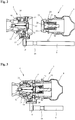
- Fig. 1 the receptacle 1 according to the invention is shown together with a storage container 2 according to the invention inserted therein.
- the receptacle 1 has a base body 3, on which a coupling designed as a snap-action coupling 4 is arranged at an inlet 5.
- the snap-action coupling 4 contains a slide element 6, which serves to detachably hold a coupling counterpart 7 at an outlet 8 of the reservoir 2.
- a torsion bar 9 is provided, which has at one end a lever 10, which bears in a sliding manner on a contact surface 6 'of the slide element 6.
- Fig. 2 shows a detailed view of the snap coupling 4 of the receptacle 1 with the coupling counterpart 7 of the reservoir 2 in uncoupled state in plan view.
- the snap-action coupling 4 has an outer housing 11 and an inner insert 12 fixedly connected thereto. Between the inner insert 12 and the outer housing 11 there is arranged a displaceable first valve element 13, which is held in a closed position by means of a first compression spring 14. In the closed position, a first sealing ring 15 seals the inner insert 12 with respect to the displaceable first valve element 13. A second sealing ring 16 also seals the displaceable first valve element 13 both in the closed position and during a displacement in an open position relative to the outer housing 11.
- a slide element 6 is movably mounted and biased by a second compression spring 17 in one direction.
- a lever 10 is provided which slidably bears against an outer contact surface 6 'of the slider element 6 and is rotatably attached to a trained as a torsion bar 9 actuator.
- the torsion bar 9 has at its end opposite the lever 10 on a key surface, not shown here, which is designed for engagement of a tool for rotating the torsion bar 9.
- actuating the torsion bar but also other lever elements, wheels or the like are conceivable.
- annular groove 18 is arranged on the torsion bar 9, in which clip elements engage the base body 3 of the receptacle 1 and thus keep the torsion bar 9 rotatable.
- positioning means for fixing the position of the torsion bar 9 in the longitudinal direction of the receptacle 1 are provided.
- the coupling counterpart 7 likewise shown has an outer housing 19 and a second valve element 20 movably arranged in the housing 19.
- the second valve element 20 is pressed by a third compression spring 21 against the outer housing 19, wherein between the second valve element 20 and the outer housing 19 for sealing a second sealing ring 22 is arranged.
- On the outside of the outer housing 19 also an oblique insertion surface 23 and an annular groove 24 are arranged.
- the coupling counterpart 7 comes over the oblique insertion surface 23 with the slide member 6 into contact and displaces it against the force of the second compression spring 17.
- the slide member engages spring actuated in the annular groove 24 of the coupling counterpart 7 and thus holds the two coupling parts together.
- the coupled state is in Fig. 3 shown.
- the outer housing 19 of the coupling counterpart comes to rest against the first valve element 13 of the snap-in coupling 4 and displaces this counter to the first compression spring 14 in an open position.
- a third sealing ring 25 is provided for sealing between the outer housing 19 and the first valve element 13.
- the fixed inner insert 12 comes into abutment against the movable second valve element 20 and also displaces it against the third compression spring 21 into an open position. Through this open position of both valve elements 13; 20 a flow of media of any kind is possible.
- Fig. 4 the release of the clutch is shown.
- the lever 10 By rotating the torsion bar 9, the lever 10 is pressed against the contact surface 6 'of the slider element 6 and displaces it against the second compression spring 17. Thereby, the slider element 6 is moved away from the holding engagement in the annular groove 24 and the coupling counterpart 7 so released.
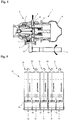
- FIG. 5 An arrangement 30 of a plurality of above-described receptacles 1a to 1e according to the invention with inserted storage containers 2a to 2e is shown in front view.
- To remove a reservoir only the respective torsion bar 9a to 9e which is arranged in the direction of insertion of the snap-in coupling and accessible from the end face of this arrangement 30, are actuated. This can be done for example via arranged on each torsion bar 9a to 9e key surfaces by means of a tool. Subsequently, the reservoir in question can be pulled out of the assembly 30.
- the use of a torsion bar and the implementation of this to the front end thus allow easy and quick change of cartridges and thus a rational workflow.
- a ventilation device 26 which can be opened via a attached to the receptacle 1 venting plunger 27.
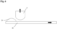
- the actuation of the snap coupling can also take place via a push rod 28 with a cam 29 arranged on it, as shown in FIG Fig. 6 is shown schematically. If, for example, the push rod 28 with the cam 29 is moved horizontally in the direction of the arrow, then the cam 29 comes into contact with the slide element 6 and pushes it upward in the direction of the arrow.
- the contour of the cam 29 and the slider element 6 are not on the in Fig. 6 shown embodiment limited. For example, angular, ramped contours or the like are also conceivable.
- the slider element 6 may also be pivotally articulated to the lever 10, so that over a rotation of the torsion bar 9, the slider element 6 can also be reciprocated between its open and its closed position.
Landscapes
- Engineering & Computer Science (AREA)
- General Engineering & Computer Science (AREA)
- Mechanical Engineering (AREA)
- Closures For Containers (AREA)
- Hydraulic Clutches, Magnetic Clutches, Fluid Clutches, And Fluid Joints (AREA)
- Containers And Packaging Bodies Having A Special Means To Remove Contents (AREA)
Description
- Die Erfindung betrifft eine Aufnahme für einen Vorratsbehälter für Zusatzstoffe in Fahrzeugbehandlungsanlagen zum selbsttätigen Halten des Vorratsbehälters nach dem Einsetzen des Vorratsbehälters in die Aufnahme, eine Anordnung solcher Aufnahmen, eine Fahrzeugbehandlungsanlage sowie eine Aufnahme mit einem Vorratsbehälter.
- Bei bekannten Fahrzeugbehandlungsanlagen, insbesondere Fahrzeugwaschanlagen, werden auf die Fahrzeuge unterschiedliche Behandlungsflüssigkeiten aufgebracht. Beispielsweise werden zu Beginn des Reinigungsvorgangs Schmutzlöser aufgebracht, welche den auf dem Fahrzeug befindlichen Schmutz anlösen und aufweichen. Anschließend wir der Schmutzlöser abgespült oder mittels Hochdruckwasserstrahl entfernt. Das eigentliche Waschschampoo wird anschließend während der nachfolgenden Bürstenwäsche aufgesprüht und danach nochmals mit klarem Wasser oder ggf. auch enthärtetem Wasser nachgespült. Abhängig vom gewünschten Waschprogramm kann dann ggf. noch ein Wachs aufgebracht werden. Üblicherweise werden diese Behandlungsflüssigkeiten dadurch bereitgestellt, dass in ein Grundmedium, in der Regel Wasser, hochdosierte Zusatzmitteln, wie z.B. Waschshampoos, Schaumbildner, Wachse, Trocknungshilfsmittel, Seifen, Felgenreiniger, Insektenentferner, etc. eindosiert werden. Diese in der Regel flüssigen oder viskosen Zusatzmittel sind üblicherweise in Vorratsbehälter abgefüllt, welche in Aufnahmen einer Dosiervorrichtung der Fahrzeugwaschanlage angeordnet und mit Dosierpumpen in das Grundmedium dosierbar sind.
- Eine solchen Vorratsbehälter offenbart die
DE 10 2007 017 615 A1 in Form einer Kartusche zum Einsetzen in eine Aufnahmevorrichtung einer Fahrzeugbehandlungseinrichtung. Bei solchen Aufnahmen besteht der Nachteil, dass die Kartuschen oft umständlich auszutauschen und schwierig zu handhaben sind. - Die
US 6 158 486 A offenbart eine Aufnahme für einen Vorratsbehälter mit einer am Einlass der Aufnahme angeordneten Kupplung. Eine daran durch Lippen gebildete lösbare Schnapp Verbindung hält den Behälter gegen eine Feder in der Aufnahme. Hierdurch wird verhindert, dass der Behälter innerhalb eines durch die Schnapp Verbindung vorgegebenen Kräftebereichs aus der Aufnahme herausgedrückt wird. Bei Überschreiten des Kräftebereichs
kann der Vorratsbehälter jedoch ohne weiteres aus der Aufnahme herausgezogen werden, eine sichere Verriegelung der Kupplung zwischen Aufnahme und Behälter findet nicht statt. - Die
US 2002/093 194 A1 offenbart eine Schnellkupplung zur Verbindung zweier Rohre mit einer Verriegelungsvorrichtung, die über einen Druckknopf eine Verriegelung der Schnellkupplung erlaubt. - Die
US 6 382 593 B1 offenbart eine Flüssigkeitskupplung zur Abgabe von Flüssigkeiten, die für den Anschluss innerhalb einer Flüssigkeitsquelle angeordneten Inlets mit einem Flüssigkeitsaufnahmeelement vorgesehen ist. Die Flüssigkeitskupplung umfasst ein Gehäuse, das einen zentralen Durchgang zwischen den vorderen und hinteren Öffnungen und einem ersten Strömungsdurchgang zwischen der Rückseite und ein Seitenöffnungen definiert. Dabei ist ein Hebelantrieb drehbar auf dem Gehäuse montiert, um den ersten Strömungsdurchgang zu Öffnen oder zu Schließen. - Die
US 2007/187 433 A1 offenbart einen Dosier- und Abgabeverschluss für einen Behälter, bei dem sich zwei drehbare Scheiben in Verbindung mit einem feststehenden Kappenelement drehen, um eine genaue Messung und Abgabe eines pulverförmigen Materials zu ermöglichen. - Die
DE 199 08 181 A1 offenbart einen in eine Aufnahme einsetzbaren Behälter mit einem Auslass, welcher mit einer Kupplung der Aufnahme verbunden wird. Über eine Schnapp Verbindung kann der Behälter in der Aufnahme gehalten werden. Auch dort kann der Behälter leicht bei Aufwenden einer vorgegebenen Kraft aus der Aufnahme herausgezogen werden. Auch dort kann keine sichere Verbindung des Auslasses des Behälters mit der Kupplung der Aufnahme sichergestellt werden, ein Herausziehen ist bei Aufbringen der dafür notwendigen Kraft ohne weiteres möglich. - Aufgabe der Erfindung ist es deshalb, ein einfaches und schnelles Wechseln des Vorratsbehälters zu ermöglichen. Zudem soll die Aufnahme platzsparend aufgebaut sein und auch im Verbund mit mehreren, nebeneinander angeordneten baugleichen Aufnahmen ein einfaches und schnelles Wechseln des Vorratsbehälters gewährleisten.
- Diese Aufgabe wird durch eine Aufnahme mit den Merkmalen des Anspruchs 1, eine Anordnung solcher Aufnahmen mit den Merkmalen des Anspruchs 9, eine Fahrzeugbehandlungsanlage mit den Merkmalen des Anspruchs 11 sowie eine Aufnahme mit einem Vorratsbehälter mit den Merkmalen des Anspruchs 12 gelöst. Vorteilhafte Ausgestaltungen der Erfindung sind in den Unteransprüchen angegeben.
- Die erfindungsgemäße Aufnahme für einen Vorratsbehälter umfasst einen Einlass zur Weiterleitung von in dem Vorratsbehälter eingebrachten Zusatzstoffen an eine Dosiervorrichtung und eine an dem Einlass angeordnete Kupplung zum lösbaren Verriegeln mit einem an einem Auslass des Behälters angeordneten Kupplungsgegenstück und einem an der Aufnahme angeordneten Betätigungselement zur Betätigung der Kupplung. Die Kupplung mit dem Betätigungselement ermöglicht ein schnelles und einfaches Wechseln der Vorratsbehälter. Bevorzugt kann die Kupplung, wie beispielsweise bei einer Schnappkupplung vorgesehen, federbewirkt in einer geschlossenen, verriegelten Stellung gehalten werden, wodurch das Betätigungselement nur zum Öffnen bzw. Entriegeln der Kupplung gebraucht wird. Nach dem Einsetzen des Vorratsbehälters wird dieser durch diese Kupplung selbsttätig sicher in der Aufnahme gehalten und kann nicht versehentlich herausgenommen werden.
- Bei der erfindungsgemäßen Aufnahme ist in der Kupplung ein Ventilelement vorgesehen, das im ungekuppelten Zustand geschlossen ist. Dies ermöglicht einen leckagefreien Wechsel und eine einfache Lagerung der Vorratsbehälter.
- Ferner ist das Betätigungselement längs der Einschubrichtung des Vorratsbehälters in der Aufnahme angeordnet, so dass bei der erfindungsgemäßen Anordnung von mindestens zwei Aufnahmen unmittelbar nebeneinander und/oder übereinander das Betätigungselement mindestens einer oder aller der Aufnahmen von der Stirnseite der oder aller Aufnahme betätigbar ist.
- In einer besonders vorteilhaften Ausführungsform kann das Betätigungselement an einem ersten Ende an eine vordere Stirnseite der Aufnahme geführt sein und an einem zweiten Ende eine Betätigungsvorrichtung zur Betätigung der Kupplung aufweisen. Hierdurch wird eine einfache Zugänglichkeit zu der Betätigungsvorrichtung und damit ein einfaches Lösen der Kupplungsverbindung ermöglicht. Bevorzugt kann hierbei das Betätigungselement in die Aufnahme fast vollständig integriert sein.
- Das Betätigungselement kann dabei besonders vorteilhaft als Schubstange ausgeführt sein, welche eine als Nocken ausgebildete Betätigungsvorrichtung zur Betätigung der Kupplung aufweist. Dies ist insbesondere bei einer Schnappkupplung von Vorteil, die federbewirkt in ihrer verriegelten Stellung gehalten wird. Durch die Nocke kann unter Ausnützung günstiger Hebelkräfte eine einfache Betätigung der Kupplung erreicht werden. Die Schubstange kann zudem vollständig in die Aufnahme integriert sein, so dass diese nicht über die Aufnahme hervorsteht und das Verletzungsrisiko reduziert sowie eine Beschädigung der Schubstange vermieden werden können. Zum Betätigen der Kupplung kann die Schubstange in ihrer Längsrichtung aus der Aufnahme herausgezogen und dabei an der Kontaktfläche des Schieberelements gleitend vorbeigezogen werden. Hierdurch wird das Schieberelement in seine geöffnete Stellung bewegt und der Vorratsbehälter kann einfach aus der Aufnahme herausgenommen werden.
- Ebenso vorteilhaft kann das Betätigungselement auch als Drehstab ausgeführt sein und eine als Hebel ausgebildete Betätigungsvorrichtung aufweisen, der die Kupplung zumindest in die geöffnete Stellung bewegt. Dies ist insbesondere bei einer Schnappkupplung von Vorteil, die federbewirkt in ihrer verriegelten Stellung gehalten wird. Die Verwendung eines Drehstabs ermöglicht einen äußerst platzsparenden Aufbau der Betätigungsvorrichtung, wobei über den Hebel dennoch ausreichend Kraft zur Betätigung der Kupplung übertragen werden kann. Eine Drehbewegung zur Betätigung der Kupplung ist besonders günstig, da dies im Vergleich zu einer Linearbewegung weniger Platz in Anspruch nimmt und geringere Reibungen auftreten.
- Vorteilhaft kann die Kupplung ein zum formschlüssigen Eingriff in eine ringförmige Nut an dem Kupplungsgegenstück des Behälters ausgebildetes Schieberelement aufweisen, wobei das Schieberelement dann über die Betätigungsvorrichtung zwischen zum Öffnen und/oder Verriegeln der Kupplung betätigbar ist. Hierzu kann das Schieberelement vorteilhaft eine Kontaktfläche für die Betätigungsvorrichtung aufweisen, wobei diese vorteilhaft zur gleitenden Anlage an der Kontaktfläche ausgebildet ist.
- Bei einer Drehung eines als Drehstabs ausgebildeten Betätigungselements wird der Hebel dann gegen das Schieberelement gedrückt, worauf dieses aus der ringförmigen Nut bewegt und die Kupplung gelöst wird. Bei der Verwendung einer Schubstange als Betätigungselement drückt diese bei einer Längsbewegung mit dem Nocken gegen das Schieberelement und löst hierdurch die Kupplung. Hierdurch ergibt sich eine einfach Konstruktion, welche die Betätigung der Kupplung auch über größere Entfernungen, insbesondere von der Stirnseite der Aufnahme aus ermöglicht.
- Besonders günstig kann es sein, wenn der Hebel oder der Nocke an einer Kontaktfläche eines Schieberelements der Kupplung gleitend anliegt. Dies ermöglicht eine einfache und verschleiß arme Kraftübertragung. Zudem können auch Fertigungstoleranzen ausgeglichen werden. Bei einer Drehung des Drehstabs wird folglich das Schieberelement von einer Haltestellung in eine Lösestellung verschoben.
- In einer vorteilhaften Weiterbildung kann der Hebel auch drehgelenkig an der Kupplung angeordnet sein, so dass die Kupplung über die Drehung des Drehstabs zwischen der geöffneten und der verriegelten Stellung hin und her bewegt werden kann. Eine Feder, welche z.B. eine Schnappkupplung in der verriegelten Stellung hält, ist dann nicht notwendig. Eine Schnappkupplung weist demgegenüber jedoch den Vorteil auf, dass der Vorratsbehälter jedoch sicher in der Aufnahme gehalten wird und der Benutzer das Verriegeln nicht vergessen kann.
- Des Weiteren kann es günstig sein, den Drehstab und den Hebel vollständig in die Aufnahme zu integrieren. Die Gefahr, den Drehstab oder den Hebel zu beschädigen wird so vermieden und es ergibt sich ein äußerst kompakter Aufbau der Aufnahme. Zudem wird hierdurch auch das Verletzungsrisiko reduziert.
- Die Aufnahme und der Drehstab können zudem in vorteilhafter Weise Positioniermittel zur Festlegung der Position des Drehstabs in seiner Längsrichtung bezüglich der Aufnahme aufweisen, damit der Hebel des Drehstabs immer in der zur Betätigung der Kupplung vorgesehenen Stellung gehalten wird, dabei aber drehbar bleibt. Solche Positioniermittel können z.B. eine Nut am Drehstab und eine in diese Nut eingreifende Erhöhung oder Clipsverbindung sein, welche den Drehstab an der Aufnahme hält.
- Vorteilhaft kann es auch sein, an der Aufnahme einen Belüftungsstempel für ein am Vorratsbehälter vorgesehenes Belüftungsventil anzuordnen. Bei einer Verbindung der Aufnahme mit dem Vorratsbehälter mittels der Kupplung wird somit gleichzeitig das Belüftungsventil betätigt, was den Einbau des Vorratsbehälters wiederum stark vereinfacht.
- Es wird außerdem eine Anordnung von mindestens zwei Aufnahmen der beschriebenen Art beansprucht. Die Aufnahmen können dabei übereinander oder nebeneinander angeordnet sein, wobei der Drehstab oder die Schubstange an eine vordere Stirnseite der Aufnahme geführt ist. Hierdurch wird eine einfache und schnelle Betätigung der Kupplung über den Drehstab oder die Schubstange gewährleistet.
- Eine Fahrzeugbehandlungsanlage weist erfindungsgemäß mindestens eine vorstehend und nachfolgend beschriebene Aufnahme bzw. Anordnung auf. Bevorzugt handelt es sich bei der Fahrzeugbehandlungsanlage um eine Fahrzeugreinigungsanlage zum Waschen von Fahrzeugen mit Waschbürsten und/oder Hochdruck, zum Aufbringen von Wachs und/oder Polieren der Fahrzeugoberflächen. Die Fahrzeugbehandlungsanlage kann vorteilhaft als Portalanlage, Durchfahranlage oder als Anlage mit Zwangsförderung der Fahrzeuge ausgestattet sein.
- Ferner betrifft die Erfindung eine Aufnahme mit einem Vorratsbehälter für Zusatzstoffe einer Fahrzeugbehandlungsanlage. Sie weist einen Auslass für die Zusatzstoffe und ein Kupplungsgegenstück auf, das mit einer an einem Einlass der Aufnahme einer Dosiervorrichtung der Fahrzeugbehandlungsanlage vorgesehenen Kupplung lösbar gekuppelt ist. Die Aufnahme ist wie oben und
nachfolgend beschrieben ausgebildet. Vorteilhaft kann der Vorratsbehälter im Auslass ein im ungekuppelten Zustand des Vorratsbehälters geschlossenes Ventilelement aufweisen, um eine Auslaufen des Vorratsbehälters vor dem Einsetzen in oder nach dem Herausnehmen aus der Aufnahme sicher zu verhindern. Bevorzugt kann das Kupplungsgegenstück des Vorratsbehälters eine ringförmige Nut zum formschlüssigen Eingriff durch ein Schieberelement der Kupplung der Aufnahme aufweisen. - Bevorzugt ist der Vorratsbehälter mit einem flüssigen oder viskosen Zusatzstoff, insbesondere Waschshampoo, Schaumbildner, Wachs, Trocknungshilfsmittel, Seife, Felgenreiniger und/oder Insektenentferner, befüllt.
- Weitere Besonderheiten und Vorzüge der Erfindung ergeben sich aus der folgenden Beschreibung bevorzugter Ausführungsbeispiele anhand der Zeichnungen. Es zeigen:
- Fig. 1
- eine Darstellung der erfindungsgemäßen Aufnahme mit einem darin eingesetzten erfindungsgemäßen Vorratsbehälter;
- Fig. 2
- eine Schnittdarstellung einer als Schnappkupplung ausgebildeten Kupplung der Aufnahme und eines Kupplungsgegenstücks des Vorratsbehälters im ungekuppelten Zustand;
- Fig. 3
- die Darstellung aus
Fig. 2 bei gekuppelter Schnappkupplung und Kupplungsgegenstück; - Fig. 4
- eine Schnittdarstellung der Schnappkupplung und des Kupplungsgegenstücks beim Entkuppeln mittels eines Drehstabs;
- Fig. 5
- eine Vorderansicht einer erfindungsgemäßen Anordnung von mehreren erfindungsgemäßen Aufnahmen mit darin angeordneten erfindungsgemäßen Vorratsbehältern;
- Fig. 6
- eine schematische Darstellung eines alternativen Betätigungselements in Form einer Schubstange mit einem Teil der Schnappkupplung.
- In
Fig. 1 ist die erfindungsgemäße Aufnahme 1 zusammen mit einem darin eingesetzten erfindungsgemäßen Vorratsbehälter 2 gezeigt. Die Aufnahme 1 weist einen Grundkörper 3 auf, an dem eine als Schnappkupplung 4 ausgebildete Kupplung an einem Einlass 5 angeordnet ist. Die Schnappkupplung 4 enthält ein Schieberelement 6, welches der lösbaren Halterung eines Kupplungsgegenstücks 7 an einem Auslass 8 des Vorratsbehälters 2 dient. Zur Betätigung der Schnappkupplung 4 ist ein Drehstab 9 vorgesehen, welcher an einem Ende einen Hebel 10 aufweist, der gleitend an einer Kontaktfläche 6' des Schieberelements 6 anliegt. -
Fig. 2 zeigt eine Detailansicht der Schnappkupplung 4 der Aufnahme 1 mit dem Kupplungsgegenstück 7 des Vorratsbehälters 2 in ungekuppelten Zustand in der Draufsicht. Die Schnappkupplung 4 besitzt ein äußeres Gehäuse 11 und einen mit diesem fest verbundenen inneren Einsatz 12. Zwischen dem inneren Einsatz 12 und dem äußeren Gehäuse 11 ist ein verschiebbares erstes Ventilelement 13 angeordnet, welches mittels einer ersten Druckfeder 14 in einer Schließstellung gehalten wird. In der Schließstellung dichtet ein erster Dichtungsring 15 den inneren Einsatz 12 gegenüber dem verschiebbaren ersten Ventilelement 13 ab. Ein zweiter Dichtungsring 16 dichtet zudem das verschiebbare erste Ventilelement 13 sowohl in der Schließstellung als auch bei einer Verschiebung in eine Öffnungsstellung gegenüber dem äußeren Gehäuse 11 ab. - Des Weiteren ist in der Schnappkupplung 4 ein Schieberelement 6 beweglich gelagert und mittels einer zweiten Druckfeder 17 in eine Richtung vorgespannt. Als Betätigungsvorrichtung des Schieberelements 6 ist ein Hebel 10 vorgesehen, welcher an einer äußeren Kontaktfläche 6' des Schieberelements 6 gleitend anliegt und an einem als Drehstab 9 ausgebildeten Betätigungselement drehfest befestigt ist. Der Drehstab 9 weist an seinem dem Hebel 10 gegenüberliegenden Ende eine hier nicht dargestellte Schlüsselfläche auf, welche zum Eingriff eines Werkzeugs zur Drehung des Drehstabs 9 ausgelegt ist. Zur Betätigung des Drehstabs sind aber auch weitere Hebelelemente, Räder oder dergleichen denkbar.
- Des Weiteren ist an dem Drehstab 9 auch eine ringförmige Nut 18 angeordnet, in welche Clipselemente an dem Grundkörper 3 der Aufnahme 1 eingreifen und so den Drehstab 9 drehbar halten. Hierdurch werden Positioniermittel zum Festlegen der Position des Drehstabs 9 in Längsrichtung der Aufnahme 1 bereitgestellt.
- Das ebenfalls dargestellte Kupplungsgegenstück 7 weist ein äußeres Gehäuse 19 und ein in dem Gehäuse 19 beweglich angeordnetes zweites Ventilelement 20 auf. Das zweite Ventilelement 20 wird durch eine dritte Druckfeder 21 gegen das äußere Gehäuse 19 gepresst, wobei zwischen dem zweiten Ventilelement 20 und dem äußeren Gehäuse 19 zur Abdichtung ein zweiter Dichtungsring 22 angeordnet ist. An der Außenseite des äußeren Gehäuses 19 sind zudem eine schräge Einschubfläche 23 und eine Ringnut 24 angeordnet.
- Bei einer Kupplung kommt das Kupplungsgegenstück 7 über die schräge Einschubfläche 23 mit dem Schieberelement 6 in Kontakt und verschiebt dieses entgegen der Kraft der zweiten Druckfeder 17. In der Schließstellung der Kupplung greift das Schieberelement federbetätigt in die Ringnut 24 des Kupplungsgegenstücks 7 ein und hält somit die beiden Kupplungsteile zusammen.
- Der gekuppelte Zustand ist in
Fig. 3 gezeigt. Das äußere Gehäuse 19 des Kupplungsgegenstücks kommt dabei zur Anlage an dem ersten Ventilelement 13 der Schnappkupplung 4 und verschiebt dieses entgegen der ersten Druckfeder 14 in eine Öffnungsstellung. Zur Abdichtung zwischen dem äußeren Gehäuse 19 und dem ersten Ventilelement 13 ist ein dritter Dichtungsring 25 vorgesehen. Bei der Kupplung kommt zudem der feste innere Einsatz 12 zur Anlage an dem beweglichen zweiten Ventilelement 20 und verschiebt dies entgegen der dritten Druckfeder 21 ebenfalls in eine Öffnungsstellung. Durch diese Öffnungsstellung beider Ventilelemente 13; 20 wird ein Durchfluss von Medien jeglicher Art ermöglicht. - In
Fig. 4 ist das Lösen der Kupplung gezeigt. Durch ein Verdrehen des Drehstabs 9 wird der Hebel 10 gegen die Kontaktfläche 6' des Schieberelements 6 gedrückt und verschiebt dieses entgegen der zweiten Druckfeder 17. Dadurch wird das Schieberelement 6 aus dem haltenden Eingriff in der Ringnut 24 wegbewegt und das Kupplungsgegenstück 7 damit freigegeben. Die Trennung der beiden Kupplungsteile, Schnappkupplung 4 und Kupplungsgegenstück 7, wird durch die Vorspannung der beiden Druckfedern 14; 21 unterstützt. - In
Fig. 5 ist eine Anordnung 30 von mehreren oben beschriebenen erfindungsgemäßen Aufnahmen 1a bis 1e mit eingesetzten Vorratsbehältern 2a bis 2e in der Vorderansicht dargestellt. Zum Herausnehmen eines Vorratsbehälters muss nur der jeweilige Drehstab 9a bis 9e welcher in Einschubrichtung der Schnappkupplung angeordnet und von der Stirnseite dieser Anordnung 30 zugänglich ist, betätigt werden. Dies kann beispielsweise über an jedem Drehstab 9a bis 9e angeordnete Schlüsselflächen mittels eines Werkzeugs erfolgen. Anschließend kann der betreffende Vorratsbehälter aus der Anordnung 30 herausgezogen werden. Die Verwendung eines Drehstabs und die Durchführung dessen an die vordere Stirnseite ermöglichen somit ein einfaches und schnelles Wechseln der Kartuschen und damit einen rationalen Arbeitsablauf. - Um den Abfluss des im Vorratsbehälter 2 bevorrateten Zusatzmittels zu erleichtern, kann vorteilhaft am Vorratsbehälter 2 eine Belüftungsvorrichtung 26 vorgesehen werden, welche über einen an der Aufnahme 1 angebrachten Belüftungsstempel 27 geöffnet werden kann. Hierdurch kann ein beim Abfluss des Zusatzmittels aus dem Vorratsbehälter 2 entstehender zunehmender Unterdruck im Vorratsbehälter 2 verhindert werden.
- Die Betätigung der Schnappkupplung kann jedoch auch über eine Schubstange 28 mit einem an dieser angeordneten Nocken 29 erfolgen, wie dies in
Fig. 6 schematisch dargestellt ist. Wird beispielsweise die Schubstange 28 mit dem Nocken 29 in Pfeilrichtung horizontal bewegt, so kommt der Nocken 29 in Kontakt mit dem Schieberelement 6 in Kontakt und drückt diese in Pfeilrichtung nach oben. Die Kontur des Nockens 29 und des Schieberelements 6 sind dabei nicht auf die inFig. 6 gezeigte Ausführungsform beschränkt. So sind beispielsweise auch eckige, rampenförmige Konturen oder dergleichen denkbar. - Anstelle der Schnappkupplung 4 können vorteilhaft auch andere geeignete, manuell betätigbare, bevorzugt selbsttätig verriegelnde, Kupplungen verwendet werden. Beispielsweise kann das Schieberelement 6 auch drehgelenkig an dem Hebel 10 angelenkt sein, so dass über eine Drehung des Drehstabs 9 das Schieberelement 6 auch zwischen seiner geöffneten und seiner geschlossenen Stellung hin- und herbewegt werden kann.
-
- 1
- Aufnahme
- 2
- Vorratsbehälter
- 3
- Grundkörper
- 4
- Schnappkupplung
- 5
- Einlass
- 6
- Schieberelement
- 6'
- Kontaktfläche an Schieberelement
- 7
- Kupplungsgegenstück
- 8
- Auslass
- 9
- Drehstab
- 10
- Hebel
- 11
- Äußeres Gehäuse der Kupplung
- 12
- Innerer Einsatz
- 13
- Erstes Ventilelement
- 14
- Erste Druckfeder
- 15
- Erster Dichtungsring
- 16
- Zweiter Dichtungsring
- 17
- Zweite Druckfeder
- 18
- Ringförmige Nut
- 19
- Äußeres Gehäuse des Kupplungsgegenstücks
- 20
- Zweites Ventilelement
- 21
- Dritte Druckfeder
- 22
- Zweiter Dichtungsring
- 23
- Schräge Einschubfläche
- 24
- Ringnut
- 25
- Dritter Dichtungsring
- 26
- Belüftungsvorrichtung
- 27
- Belüftungsstempel
- 28
- Schubstange
- 29
- Nocken
- 30
- Anordnung von mehreren Aufnahmen
Claims (13)
- Aufnahme (1) für einen Vorratsbehälter (2) von Zusatzstoffen in einer Fahrzeugbehandlungsanlage zum selbsttätigen Halten des Vorratsbehälters (2) nach dem Einsetzen des Vorratsbehälters (2) in die Aufnahme (1), mit einem Einlass (5) zur Weiterleitung der Zusatzstoffe an eine Dosiervorrichtung, einer an dem Einlass (5) angeordneten Kupplung (4) zum lösbaren Verriegeln mit einem an einem Auslass (8) des Behälters (2) angeordneten Kupplungsgegenstück (7), dadurch gekennzeichnet
dass an der Aufnahme (1) ein Betätigungselement (9; 28) zur Betätigung der Kupplung (4) angeordnet ist,
dass in der Kupplung (4) ein Ventilelement (13) vorgesehen ist, das im ungekuppelten Zustand geschlossen ist und
dass das Betätigungselement (9; 28) längs der Einschubrichtung des Vorratsbehälters (2) in der Aufnahme (1) angeordnet ist. - Aufnahme nach Anspruch 1, dadurch gekennzeichnet, dass das Betätigungselement (9; 28) an einem ersten Ende an eine vordere Stirnseite der Aufnahme (1) geführt ist und an einem zweiten Ende eine Betätigungsvorrichtung (10; 29) zur Betätigung der Kupplung (4) angeordnet ist.
- Aufnahme nach Anspruch 2, dadurch gekennzeichnet, dass die Kupplung (4) ein zum formschlüssigen Eingriff in eine ringförmige Nut (18) an dem Kupplungsgegenstück (7) des Vorratsbehälters (2) ausgebildetes Schieberelement (6) aufweist.
- Aufnahme nach Anspruch 3, dadurch gekennzeichnet, dass das Schieberelement (6) eine Kontaktfläche (6') für die Betätigungsvorrichtung (10; 29) aufweist.
- Aufnahme nach Anspruch 4, dadurch gekennzeichnet, dass die Betätigungsvorrichtung (10; 29) zur gleitenden Anlage an der Kontaktfläche (6') ausgebildet ist.
- Aufnahme nach einem der Ansprüche 2 bis 5, dadurch gekennzeichnet, dass das Betätigungselement als Drehstab (9) und die Betätigungsvorrichtung als Hebel (10) zum Öffnen der Kupplung (4) ausgebildet sind.
- Aufnahme nach Anspruch 6, dadurch gekennzeichnet, dass die Kupplung (4) durch eine Drehung des Drehstabs (9) mittels des Hebels (10) lösbar ist.
- Aufnahme nach einem der Ansprüche 6 oder 7, dadurch gekennzeichnet, dass an der Aufnahme (1) und dem Drehstab (9) Positioniermittel zur Festlegung der Position des Drehstabs (9) in seiner Längsrichtung bezüglich der Aufnahme (1) vorgesehen sind.
- Anordnung (30) von mindestens zwei Aufnahmen nach einem der Ansprüche 1 bis 8, dadurch gekennzeichnet, dass die Aufnahmen (1) unmittelbar nebeneinander und/oder übereinander angeordnet sind und das Betätigungselement (9) mindestens einer der Aufnahmen (1) von der Stirnseite der Aufnahme (1) betätigbar ist.
- Anordnung nach Anspruch 9, dadurch gekennzeichnet, dass die Betätigungselemente (9) aller Aufnahmen (1) von den Stirnseiten der Aufnahmen (1) betätigbar sind.
- Fahrzeugbehandlungsanlage mit mindestens einer Aufnahme nach einem der Ansprüche 1 bis 8, insbesondere in einer Anordnung (30) nach einem der Ansprüche 9 oder 10.
- Aufnahme (1) mit einem Vorratsbehälter (2) für Zusatzstoffe einer Fahrzeugbehandlungsanlage, mit einem Auslass (8) für die Zusatzstoffe und einem Kupplungsgegenstück (7), das mit einer an einem Einlass (5) der Aufnahme (1) nach einem der Ansprüche 1 bis 8 einer Dosiervorrichtung der Fahrzeugbehandlungsanlage vorgesehenen Kupplung (4) lösbar gekuppelt ist, wobei das Kupplungsgegenstück (7) eine schräge Einschubfläche (23) und eine ringförmige Nut (18) zum formschlüssigen Eingriff durch ein Schieberelement (6) der Kupplung (4) aufweist.
- Aufnahme (1) nach Anspruch 12, dadurch gekennzeichnet, dass im Auslass (8) ein im ungekuppelten Zustand des Vorratsbehälters (2) geschlossenes Ventilelement (20) vorgesehen ist.
Applications Claiming Priority (2)
| Application Number | Priority Date | Filing Date | Title |
|---|---|---|---|
| DE102012107628.6A DE102012107628B4 (de) | 2012-08-20 | 2012-08-20 | Aufnahme für einen Vorratsbehälter, Anordnung solcher Aufnahmen, Fahrzeugbehandlungsanlage und Vorratsbehälter |
| PCT/EP2013/067229 WO2014029730A1 (de) | 2012-08-20 | 2013-08-19 | Aufnahme für einen vorratsbehälter, anordnung solcher aufnahmen, fahrzeugbehandlungsanlage und vorratsbehälter |
Publications (2)
| Publication Number | Publication Date |
|---|---|
| EP2885566A1 EP2885566A1 (de) | 2015-06-24 |
| EP2885566B1 true EP2885566B1 (de) | 2018-10-10 |
Family
ID=49035559
Family Applications (1)
| Application Number | Title | Priority Date | Filing Date |
|---|---|---|---|
| EP13753145.5A Not-in-force EP2885566B1 (de) | 2012-08-20 | 2013-08-19 | Aufnahme für einen vorratsbehälter, anordnung solcher aufnahmen, fahrzeugbehandlungsanlage und vorratsbehälter |
Country Status (3)
| Country | Link |
|---|---|
| EP (1) | EP2885566B1 (de) |
| DE (1) | DE102012107628B4 (de) |
| WO (1) | WO2014029730A1 (de) |
Family Cites Families (6)
| Publication number | Priority date | Publication date | Assignee | Title |
|---|---|---|---|---|
| US6109480A (en) | 1998-07-27 | 2000-08-29 | Ecolab Inc. | Liquid dispenser and docking station for mating container |
| US6158486A (en) | 1998-11-19 | 2000-12-12 | Ecolab Inc. | Closed package liquid dispensing system |
| US6382593B1 (en) * | 2000-03-06 | 2002-05-07 | Colder Products Company | Fluid coupling |
| FR2819038A1 (fr) * | 2000-12-28 | 2002-07-05 | Staubli Sa Ets | Element femelle d'un raccord et raccord rapide incorporant un tel element |
| US7950550B2 (en) * | 2004-05-06 | 2011-05-31 | Diversey, Inc. | Metering and dispensing closure |
| DE102007017615B4 (de) | 2007-04-12 | 2018-01-04 | Washtec Holding Gmbh | Fahrzeugwaschanlage und Verfahren zur Dosierung von Zusatzstoffen in Behandlungsflüssigkeiten |
-
2012
- 2012-08-20 DE DE102012107628.6A patent/DE102012107628B4/de not_active Expired - Fee Related
-
2013
- 2013-08-19 EP EP13753145.5A patent/EP2885566B1/de not_active Not-in-force
- 2013-08-19 WO PCT/EP2013/067229 patent/WO2014029730A1/de not_active Ceased
Non-Patent Citations (1)
| Title |
|---|
| None * |
Also Published As
| Publication number | Publication date |
|---|---|
| DE102012107628B4 (de) | 2019-05-29 |
| DE102012107628A1 (de) | 2014-03-13 |
| WO2014029730A1 (de) | 2014-02-27 |
| EP2885566A1 (de) | 2015-06-24 |
Similar Documents
| Publication | Publication Date | Title |
|---|---|---|
| DE69731772T2 (de) | Kupplung | |
| DE69325653T2 (de) | Verschlussvorrichtung | |
| DE102009034715A1 (de) | Spritzgusswerkzeug, Verfahren zum Spritzgießen eines Spritzgussbauteils sowie Verschluss- und/oder Anschlusseinrichtung eines Spritzpistolenfarbbechers | |
| DE2736551A1 (de) | Pipette | |
| EP0455650B1 (de) | Zapfkopf für keg-armaturen | |
| DE202016100531U1 (de) | Injektionsvorrichtung | |
| DE10038882A1 (de) | Vorrichtung zum Ausgeben einer gemischten Mehrkomponentenmasse, insbesondere für zahnärztliche Zwecke | |
| EP2682661A1 (de) | Vorrichtung zur kontaminationsfreien Befüllung eines Tanks aus einem Kanister | |
| EP3181245A1 (de) | Düsenanordnung für fliessfähige substanzen | |
| EP2130609B1 (de) | Austragvorrichtung für Medien | |
| EP1826393B1 (de) | Filtersystem für Flüssigkeiten | |
| DE202016101580U1 (de) | Selbstschließender Ausgabekopf für einen Druckbehälter | |
| EP0796668A1 (de) | Vorrichtung zum Auftragen von Farbe auf Flächen | |
| DE102007044180A1 (de) | Selbstschließender Ausgabekopf | |
| DE202006020389U1 (de) | Vorrichtung zum Füllen eines Aerosolbehälters mit Flüssigkeit, Fülleinrichtung, die dazu geeignet ist, eine derartige Vorrichtung aufzunehmen und Verschlusskappe und Aerosolbehälter, der mit einer derartigen Füllvorichtung ausgerüstet ist | |
| DE2624013C2 (de) | Rohr- oder Schlauchleitungskupplung | |
| DE2823886A1 (de) | Kuppler zum anschliessen an ein einsatzstueck | |
| EP2858864B1 (de) | Vorratsbehälter, aufnahme für einen vorratsbehälter und fahrzeugbehandlungsanlage | |
| DE102012107628B4 (de) | Aufnahme für einen Vorratsbehälter, Anordnung solcher Aufnahmen, Fahrzeugbehandlungsanlage und Vorratsbehälter | |
| DE202012103146U1 (de) | Vorratsbehälter, Aufnahme für einen Vorratsbehälter und Fahrzeugbehandlungsanlage | |
| EP3429869B1 (de) | Vorrichtung zum spitzen von stiften | |
| EP4358894B1 (de) | Adapter zur kopplung eines hohlkörpers im medizinischen bereich mit einem vorratsbehälter für ein behandlungsmittel | |
| EP1336484B1 (de) | Waschvorrichtung für Druckmaschinenzylinder | |
| DE102018109370A1 (de) | Form zur Herstellung eines Gussartikels, umfassend eine Vorrichtung zum Auswerfen eines rohrförmigen Teils des Gussartikel | |
| EP1660239B1 (de) | Vorrichtung zum füllen von vorratsbehältern an austraggeräten |
Legal Events
| Date | Code | Title | Description |
|---|---|---|---|
| PUAI | Public reference made under article 153(3) epc to a published international application that has entered the european phase |
Free format text: ORIGINAL CODE: 0009012 |
|
| 17P | Request for examination filed |
Effective date: 20150320 |
|
| AK | Designated contracting states |
Kind code of ref document: A1 Designated state(s): AL AT BE BG CH CY CZ DE DK EE ES FI FR GB GR HR HU IE IS IT LI LT LU LV MC MK MT NL NO PL PT RO RS SE SI SK SM TR |
|
| AX | Request for extension of the european patent |
Extension state: BA ME |
|
| DAX | Request for extension of the european patent (deleted) | ||
| 17Q | First examination report despatched |
Effective date: 20160420 |
|
| STAA | Information on the status of an ep patent application or granted ep patent |
Free format text: STATUS: EXAMINATION IS IN PROGRESS |
|
| GRAP | Despatch of communication of intention to grant a patent |
Free format text: ORIGINAL CODE: EPIDOSNIGR1 |
|
| STAA | Information on the status of an ep patent application or granted ep patent |
Free format text: STATUS: GRANT OF PATENT IS INTENDED |
|
| INTG | Intention to grant announced |
Effective date: 20180409 |
|
| GRAS | Grant fee paid |
Free format text: ORIGINAL CODE: EPIDOSNIGR3 |
|
| GRAJ | Information related to disapproval of communication of intention to grant by the applicant or resumption of examination proceedings by the epo deleted |
Free format text: ORIGINAL CODE: EPIDOSDIGR1 |
|
| GRAL | Information related to payment of fee for publishing/printing deleted |
Free format text: ORIGINAL CODE: EPIDOSDIGR3 |
|
| STAA | Information on the status of an ep patent application or granted ep patent |
Free format text: STATUS: EXAMINATION IS IN PROGRESS |
|
| GRAR | Information related to intention to grant a patent recorded |
Free format text: ORIGINAL CODE: EPIDOSNIGR71 |
|
| STAA | Information on the status of an ep patent application or granted ep patent |
Free format text: STATUS: GRANT OF PATENT IS INTENDED |
|
| INTC | Intention to grant announced (deleted) | ||
| INTG | Intention to grant announced |
Effective date: 20180718 |
|
| GRAA | (expected) grant |
Free format text: ORIGINAL CODE: 0009210 |
|
| STAA | Information on the status of an ep patent application or granted ep patent |
Free format text: STATUS: THE PATENT HAS BEEN GRANTED |
|
| AK | Designated contracting states |
Kind code of ref document: B1 Designated state(s): AL AT BE BG CH CY CZ DE DK EE ES FI FR GB GR HR HU IE IS IT LI LT LU LV MC MK MT NL NO PL PT RO RS SE SI SK SM TR |
|
| REG | Reference to a national code |
Ref country code: GB Ref legal event code: FG4D Free format text: NOT ENGLISH |
|
| REG | Reference to a national code |
Ref country code: CH Ref legal event code: EP Ref country code: AT Ref legal event code: REF Ref document number: 1051651 Country of ref document: AT Kind code of ref document: T Effective date: 20181015 |
|
| REG | Reference to a national code |
Ref country code: IE Ref legal event code: FG4D Free format text: LANGUAGE OF EP DOCUMENT: GERMAN |
|
| REG | Reference to a national code |
Ref country code: DE Ref legal event code: R096 Ref document number: 502013011313 Country of ref document: DE |
|
| REG | Reference to a national code |
Ref country code: NL Ref legal event code: MP Effective date: 20181010 |
|
| REG | Reference to a national code |
Ref country code: LT Ref legal event code: MG4D |
|
| PG25 | Lapsed in a contracting state [announced via postgrant information from national office to epo] |
Ref country code: NL Free format text: LAPSE BECAUSE OF FAILURE TO SUBMIT A TRANSLATION OF THE DESCRIPTION OR TO PAY THE FEE WITHIN THE PRESCRIBED TIME-LIMIT Effective date: 20181010 |
|
| PG25 | Lapsed in a contracting state [announced via postgrant information from national office to epo] |
Ref country code: HR Free format text: LAPSE BECAUSE OF FAILURE TO SUBMIT A TRANSLATION OF THE DESCRIPTION OR TO PAY THE FEE WITHIN THE PRESCRIBED TIME-LIMIT Effective date: 20181010 Ref country code: PL Free format text: LAPSE BECAUSE OF FAILURE TO SUBMIT A TRANSLATION OF THE DESCRIPTION OR TO PAY THE FEE WITHIN THE PRESCRIBED TIME-LIMIT Effective date: 20181010 Ref country code: LT Free format text: LAPSE BECAUSE OF FAILURE TO SUBMIT A TRANSLATION OF THE DESCRIPTION OR TO PAY THE FEE WITHIN THE PRESCRIBED TIME-LIMIT Effective date: 20181010 Ref country code: ES Free format text: LAPSE BECAUSE OF FAILURE TO SUBMIT A TRANSLATION OF THE DESCRIPTION OR TO PAY THE FEE WITHIN THE PRESCRIBED TIME-LIMIT Effective date: 20181010 Ref country code: FI Free format text: LAPSE BECAUSE OF FAILURE TO SUBMIT A TRANSLATION OF THE DESCRIPTION OR TO PAY THE FEE WITHIN THE PRESCRIBED TIME-LIMIT Effective date: 20181010 Ref country code: BG Free format text: LAPSE BECAUSE OF FAILURE TO SUBMIT A TRANSLATION OF THE DESCRIPTION OR TO PAY THE FEE WITHIN THE PRESCRIBED TIME-LIMIT Effective date: 20190110 Ref country code: LV Free format text: LAPSE BECAUSE OF FAILURE TO SUBMIT A TRANSLATION OF THE DESCRIPTION OR TO PAY THE FEE WITHIN THE PRESCRIBED TIME-LIMIT Effective date: 20181010 Ref country code: IS Free format text: LAPSE BECAUSE OF FAILURE TO SUBMIT A TRANSLATION OF THE DESCRIPTION OR TO PAY THE FEE WITHIN THE PRESCRIBED TIME-LIMIT Effective date: 20190210 Ref country code: NO Free format text: LAPSE BECAUSE OF FAILURE TO SUBMIT A TRANSLATION OF THE DESCRIPTION OR TO PAY THE FEE WITHIN THE PRESCRIBED TIME-LIMIT Effective date: 20190110 |
|
| PG25 | Lapsed in a contracting state [announced via postgrant information from national office to epo] |
Ref country code: RS Free format text: LAPSE BECAUSE OF FAILURE TO SUBMIT A TRANSLATION OF THE DESCRIPTION OR TO PAY THE FEE WITHIN THE PRESCRIBED TIME-LIMIT Effective date: 20181010 Ref country code: GR Free format text: LAPSE BECAUSE OF FAILURE TO SUBMIT A TRANSLATION OF THE DESCRIPTION OR TO PAY THE FEE WITHIN THE PRESCRIBED TIME-LIMIT Effective date: 20190111 Ref country code: PT Free format text: LAPSE BECAUSE OF FAILURE TO SUBMIT A TRANSLATION OF THE DESCRIPTION OR TO PAY THE FEE WITHIN THE PRESCRIBED TIME-LIMIT Effective date: 20190210 Ref country code: AL Free format text: LAPSE BECAUSE OF FAILURE TO SUBMIT A TRANSLATION OF THE DESCRIPTION OR TO PAY THE FEE WITHIN THE PRESCRIBED TIME-LIMIT Effective date: 20181010 Ref country code: SE Free format text: LAPSE BECAUSE OF FAILURE TO SUBMIT A TRANSLATION OF THE DESCRIPTION OR TO PAY THE FEE WITHIN THE PRESCRIBED TIME-LIMIT Effective date: 20181010 |
|
| REG | Reference to a national code |
Ref country code: DE Ref legal event code: R097 Ref document number: 502013011313 Country of ref document: DE |
|
| PG25 | Lapsed in a contracting state [announced via postgrant information from national office to epo] |
Ref country code: DK Free format text: LAPSE BECAUSE OF FAILURE TO SUBMIT A TRANSLATION OF THE DESCRIPTION OR TO PAY THE FEE WITHIN THE PRESCRIBED TIME-LIMIT Effective date: 20181010 Ref country code: CZ Free format text: LAPSE BECAUSE OF FAILURE TO SUBMIT A TRANSLATION OF THE DESCRIPTION OR TO PAY THE FEE WITHIN THE PRESCRIBED TIME-LIMIT Effective date: 20181010 Ref country code: IT Free format text: LAPSE BECAUSE OF FAILURE TO SUBMIT A TRANSLATION OF THE DESCRIPTION OR TO PAY THE FEE WITHIN THE PRESCRIBED TIME-LIMIT Effective date: 20181010 |
|
| PLBE | No opposition filed within time limit |
Free format text: ORIGINAL CODE: 0009261 |
|
| STAA | Information on the status of an ep patent application or granted ep patent |
Free format text: STATUS: NO OPPOSITION FILED WITHIN TIME LIMIT |
|
| PG25 | Lapsed in a contracting state [announced via postgrant information from national office to epo] |
Ref country code: SK Free format text: LAPSE BECAUSE OF FAILURE TO SUBMIT A TRANSLATION OF THE DESCRIPTION OR TO PAY THE FEE WITHIN THE PRESCRIBED TIME-LIMIT Effective date: 20181010 Ref country code: SM Free format text: LAPSE BECAUSE OF FAILURE TO SUBMIT A TRANSLATION OF THE DESCRIPTION OR TO PAY THE FEE WITHIN THE PRESCRIBED TIME-LIMIT Effective date: 20181010 Ref country code: EE Free format text: LAPSE BECAUSE OF FAILURE TO SUBMIT A TRANSLATION OF THE DESCRIPTION OR TO PAY THE FEE WITHIN THE PRESCRIBED TIME-LIMIT Effective date: 20181010 Ref country code: RO Free format text: LAPSE BECAUSE OF FAILURE TO SUBMIT A TRANSLATION OF THE DESCRIPTION OR TO PAY THE FEE WITHIN THE PRESCRIBED TIME-LIMIT Effective date: 20181010 |
|
| 26N | No opposition filed |
Effective date: 20190711 |
|
| PG25 | Lapsed in a contracting state [announced via postgrant information from national office to epo] |
Ref country code: SI Free format text: LAPSE BECAUSE OF FAILURE TO SUBMIT A TRANSLATION OF THE DESCRIPTION OR TO PAY THE FEE WITHIN THE PRESCRIBED TIME-LIMIT Effective date: 20181010 |
|
| REG | Reference to a national code |
Ref country code: DE Ref legal event code: R119 Ref document number: 502013011313 Country of ref document: DE |
|
| PG25 | Lapsed in a contracting state [announced via postgrant information from national office to epo] |
Ref country code: TR Free format text: LAPSE BECAUSE OF FAILURE TO SUBMIT A TRANSLATION OF THE DESCRIPTION OR TO PAY THE FEE WITHIN THE PRESCRIBED TIME-LIMIT Effective date: 20181010 |
|
| GBPC | Gb: european patent ceased through non-payment of renewal fee |
Effective date: 20190819 |
|
| PG25 | Lapsed in a contracting state [announced via postgrant information from national office to epo] |
Ref country code: LI Free format text: LAPSE BECAUSE OF NON-PAYMENT OF DUE FEES Effective date: 20190831 Ref country code: MC Free format text: LAPSE BECAUSE OF FAILURE TO SUBMIT A TRANSLATION OF THE DESCRIPTION OR TO PAY THE FEE WITHIN THE PRESCRIBED TIME-LIMIT Effective date: 20181010 Ref country code: CH Free format text: LAPSE BECAUSE OF NON-PAYMENT OF DUE FEES Effective date: 20190831 Ref country code: LU Free format text: LAPSE BECAUSE OF NON-PAYMENT OF DUE FEES Effective date: 20190819 |
|
| REG | Reference to a national code |
Ref country code: BE Ref legal event code: MM Effective date: 20190831 |
|
| PG25 | Lapsed in a contracting state [announced via postgrant information from national office to epo] |
Ref country code: FR Free format text: LAPSE BECAUSE OF NON-PAYMENT OF DUE FEES Effective date: 20190831 Ref country code: IE Free format text: LAPSE BECAUSE OF NON-PAYMENT OF DUE FEES Effective date: 20190819 Ref country code: DE Free format text: LAPSE BECAUSE OF NON-PAYMENT OF DUE FEES Effective date: 20200303 |
|
| PG25 | Lapsed in a contracting state [announced via postgrant information from national office to epo] |
Ref country code: BE Free format text: LAPSE BECAUSE OF NON-PAYMENT OF DUE FEES Effective date: 20190831 Ref country code: GB Free format text: LAPSE BECAUSE OF NON-PAYMENT OF DUE FEES Effective date: 20190819 |
|
| REG | Reference to a national code |
Ref country code: AT Ref legal event code: MM01 Ref document number: 1051651 Country of ref document: AT Kind code of ref document: T Effective date: 20190819 |
|
| PG25 | Lapsed in a contracting state [announced via postgrant information from national office to epo] |
Ref country code: AT Free format text: LAPSE BECAUSE OF NON-PAYMENT OF DUE FEES Effective date: 20190819 |
|
| PG25 | Lapsed in a contracting state [announced via postgrant information from national office to epo] |
Ref country code: CY Free format text: LAPSE BECAUSE OF FAILURE TO SUBMIT A TRANSLATION OF THE DESCRIPTION OR TO PAY THE FEE WITHIN THE PRESCRIBED TIME-LIMIT Effective date: 20181010 |
|
| PG25 | Lapsed in a contracting state [announced via postgrant information from national office to epo] |
Ref country code: MT Free format text: LAPSE BECAUSE OF FAILURE TO SUBMIT A TRANSLATION OF THE DESCRIPTION OR TO PAY THE FEE WITHIN THE PRESCRIBED TIME-LIMIT Effective date: 20181010 Ref country code: HU Free format text: LAPSE BECAUSE OF FAILURE TO SUBMIT A TRANSLATION OF THE DESCRIPTION OR TO PAY THE FEE WITHIN THE PRESCRIBED TIME-LIMIT; INVALID AB INITIO Effective date: 20130819 |
|
| PG25 | Lapsed in a contracting state [announced via postgrant information from national office to epo] |
Ref country code: MK Free format text: LAPSE BECAUSE OF FAILURE TO SUBMIT A TRANSLATION OF THE DESCRIPTION OR TO PAY THE FEE WITHIN THE PRESCRIBED TIME-LIMIT Effective date: 20181010 |