EP2885142B1 - Operating device for adjusting an air conditioning device of a vehicle and corresponding method - Google Patents
Operating device for adjusting an air conditioning device of a vehicle and corresponding method Download PDFInfo
- Publication number
- EP2885142B1 EP2885142B1 EP13744556.5A EP13744556A EP2885142B1 EP 2885142 B1 EP2885142 B1 EP 2885142B1 EP 13744556 A EP13744556 A EP 13744556A EP 2885142 B1 EP2885142 B1 EP 2885142B1
- Authority
- EP
- European Patent Office
- Prior art keywords
- touch
- vehicle
- sensitive surface
- switching
- display
- Prior art date
- Legal status (The legal status is an assumption and is not a legal conclusion. Google has not performed a legal analysis and makes no representation as to the accuracy of the status listed.)
- Active
Links
- 238000004378 air conditioning Methods 0.000 title claims description 33
- 238000000034 method Methods 0.000 title claims description 18
- 238000001514 detection method Methods 0.000 claims description 45
- 238000009423 ventilation Methods 0.000 claims description 40
- 238000013459 approach Methods 0.000 claims description 10
- 230000005855 radiation Effects 0.000 description 8
- 230000008859 change Effects 0.000 description 6
- 230000003247 decreasing effect Effects 0.000 description 5
- 239000011888 foil Substances 0.000 description 3
- 238000013022 venting Methods 0.000 description 3
- 230000008901 benefit Effects 0.000 description 2
- 238000011161 development Methods 0.000 description 2
- 230000018109 developmental process Effects 0.000 description 2
- 238000010079 rubber tapping Methods 0.000 description 2
- 230000004888 barrier function Effects 0.000 description 1
- 238000004891 communication Methods 0.000 description 1
- 230000003750 conditioning effect Effects 0.000 description 1
- 230000001276 controlling effect Effects 0.000 description 1
- 230000008878 coupling Effects 0.000 description 1
- 238000010168 coupling process Methods 0.000 description 1
- 238000005859 coupling reaction Methods 0.000 description 1
- 230000001419 dependent effect Effects 0.000 description 1
- 230000012447 hatching Effects 0.000 description 1
- 238000005286 illumination Methods 0.000 description 1
- 239000004973 liquid crystal related substance Substances 0.000 description 1
- 230000001105 regulatory effect Effects 0.000 description 1
- 230000004044 response Effects 0.000 description 1
- 230000002123 temporal effect Effects 0.000 description 1
Images


Classifications
-
- B—PERFORMING OPERATIONS; TRANSPORTING
- B60—VEHICLES IN GENERAL
- B60K—ARRANGEMENT OR MOUNTING OF PROPULSION UNITS OR OF TRANSMISSIONS IN VEHICLES; ARRANGEMENT OR MOUNTING OF PLURAL DIVERSE PRIME-MOVERS IN VEHICLES; AUXILIARY DRIVES FOR VEHICLES; INSTRUMENTATION OR DASHBOARDS FOR VEHICLES; ARRANGEMENTS IN CONNECTION WITH COOLING, AIR INTAKE, GAS EXHAUST OR FUEL SUPPLY OF PROPULSION UNITS IN VEHICLES
- B60K35/00—Instruments specially adapted for vehicles; Arrangement of instruments in or on vehicles
-
- B—PERFORMING OPERATIONS; TRANSPORTING
- B60—VEHICLES IN GENERAL
- B60H—ARRANGEMENTS OF HEATING, COOLING, VENTILATING OR OTHER AIR-TREATING DEVICES SPECIALLY ADAPTED FOR PASSENGER OR GOODS SPACES OF VEHICLES
- B60H1/00—Heating, cooling or ventilating [HVAC] devices
- B60H1/00642—Control systems or circuits; Control members or indication devices for heating, cooling or ventilating devices
- B60H1/0065—Control members, e.g. levers or knobs
-
- B—PERFORMING OPERATIONS; TRANSPORTING
- B60—VEHICLES IN GENERAL
- B60H—ARRANGEMENTS OF HEATING, COOLING, VENTILATING OR OTHER AIR-TREATING DEVICES SPECIALLY ADAPTED FOR PASSENGER OR GOODS SPACES OF VEHICLES
- B60H1/00—Heating, cooling or ventilating [HVAC] devices
- B60H1/00642—Control systems or circuits; Control members or indication devices for heating, cooling or ventilating devices
- B60H1/00814—Control systems or circuits characterised by their output, for controlling particular components of the heating, cooling or ventilating installation
- B60H1/00821—Control systems or circuits characterised by their output, for controlling particular components of the heating, cooling or ventilating installation the components being ventilating, air admitting or air distributing devices
- B60H1/00871—Air directing means, e.g. blades in an air outlet
-
- B—PERFORMING OPERATIONS; TRANSPORTING
- B60—VEHICLES IN GENERAL
- B60H—ARRANGEMENTS OF HEATING, COOLING, VENTILATING OR OTHER AIR-TREATING DEVICES SPECIALLY ADAPTED FOR PASSENGER OR GOODS SPACES OF VEHICLES
- B60H1/00—Heating, cooling or ventilating [HVAC] devices
- B60H1/00642—Control systems or circuits; Control members or indication devices for heating, cooling or ventilating devices
- B60H1/00985—Control systems or circuits characterised by display or indicating devices, e.g. voice simulators
-
- B—PERFORMING OPERATIONS; TRANSPORTING
- B60—VEHICLES IN GENERAL
- B60K—ARRANGEMENT OR MOUNTING OF PROPULSION UNITS OR OF TRANSMISSIONS IN VEHICLES; ARRANGEMENT OR MOUNTING OF PLURAL DIVERSE PRIME-MOVERS IN VEHICLES; AUXILIARY DRIVES FOR VEHICLES; INSTRUMENTATION OR DASHBOARDS FOR VEHICLES; ARRANGEMENTS IN CONNECTION WITH COOLING, AIR INTAKE, GAS EXHAUST OR FUEL SUPPLY OF PROPULSION UNITS IN VEHICLES
- B60K35/00—Instruments specially adapted for vehicles; Arrangement of instruments in or on vehicles
- B60K35/10—Input arrangements, i.e. from user to vehicle, associated with vehicle functions or specially adapted therefor
-
- B—PERFORMING OPERATIONS; TRANSPORTING
- B60—VEHICLES IN GENERAL
- B60K—ARRANGEMENT OR MOUNTING OF PROPULSION UNITS OR OF TRANSMISSIONS IN VEHICLES; ARRANGEMENT OR MOUNTING OF PLURAL DIVERSE PRIME-MOVERS IN VEHICLES; AUXILIARY DRIVES FOR VEHICLES; INSTRUMENTATION OR DASHBOARDS FOR VEHICLES; ARRANGEMENTS IN CONNECTION WITH COOLING, AIR INTAKE, GAS EXHAUST OR FUEL SUPPLY OF PROPULSION UNITS IN VEHICLES
- B60K35/00—Instruments specially adapted for vehicles; Arrangement of instruments in or on vehicles
- B60K35/20—Output arrangements, i.e. from vehicle to user, associated with vehicle functions or specially adapted therefor
- B60K35/28—Output arrangements, i.e. from vehicle to user, associated with vehicle functions or specially adapted therefor characterised by the type of the output information, e.g. video entertainment or vehicle dynamics information; characterised by the purpose of the output information, e.g. for attracting the attention of the driver
-
- B—PERFORMING OPERATIONS; TRANSPORTING
- B60—VEHICLES IN GENERAL
- B60K—ARRANGEMENT OR MOUNTING OF PROPULSION UNITS OR OF TRANSMISSIONS IN VEHICLES; ARRANGEMENT OR MOUNTING OF PLURAL DIVERSE PRIME-MOVERS IN VEHICLES; AUXILIARY DRIVES FOR VEHICLES; INSTRUMENTATION OR DASHBOARDS FOR VEHICLES; ARRANGEMENTS IN CONNECTION WITH COOLING, AIR INTAKE, GAS EXHAUST OR FUEL SUPPLY OF PROPULSION UNITS IN VEHICLES
- B60K2360/00—Indexing scheme associated with groups B60K35/00 or B60K37/00 relating to details of instruments or dashboards
- B60K2360/143—Touch sensitive instrument input devices
- B60K2360/1438—Touch screens
-
- B—PERFORMING OPERATIONS; TRANSPORTING
- B60—VEHICLES IN GENERAL
- B60K—ARRANGEMENT OR MOUNTING OF PROPULSION UNITS OR OF TRANSMISSIONS IN VEHICLES; ARRANGEMENT OR MOUNTING OF PLURAL DIVERSE PRIME-MOVERS IN VEHICLES; AUXILIARY DRIVES FOR VEHICLES; INSTRUMENTATION OR DASHBOARDS FOR VEHICLES; ARRANGEMENTS IN CONNECTION WITH COOLING, AIR INTAKE, GAS EXHAUST OR FUEL SUPPLY OF PROPULSION UNITS IN VEHICLES
- B60K2360/00—Indexing scheme associated with groups B60K35/00 or B60K37/00 relating to details of instruments or dashboards
- B60K2360/16—Type of output information
- B60K2360/161—Explanation of functions, e.g. instructions
-
- B—PERFORMING OPERATIONS; TRANSPORTING
- B60—VEHICLES IN GENERAL
- B60K—ARRANGEMENT OR MOUNTING OF PROPULSION UNITS OR OF TRANSMISSIONS IN VEHICLES; ARRANGEMENT OR MOUNTING OF PLURAL DIVERSE PRIME-MOVERS IN VEHICLES; AUXILIARY DRIVES FOR VEHICLES; INSTRUMENTATION OR DASHBOARDS FOR VEHICLES; ARRANGEMENTS IN CONNECTION WITH COOLING, AIR INTAKE, GAS EXHAUST OR FUEL SUPPLY OF PROPULSION UNITS IN VEHICLES
- B60K2360/00—Indexing scheme associated with groups B60K35/00 or B60K37/00 relating to details of instruments or dashboards
- B60K2360/16—Type of output information
- B60K2360/165—Videos and animations
Definitions
- the present invention relates to an operating device for setting an air conditioning device of a vehicle.
- the air conditioning device comprises ventilation elements for conditioning the interior of the vehicle.
- the operating device has a display surface and an input device for inputting control commands for the air conditioning device of the vehicle.
- the operating device comprises a control device, which is coupled to the display surface and the input device with which graphics data can be generated for a display on the display surface. With the control device, control commands entered by means of the input device can be converted into control signals for the air conditioning device of the vehicle.
- the invention relates to a method for adjusting an air conditioning device of a vehicle.
- a motor vehicle there are a variety of functional devices that are required to run the vehicle, which serve the safety and comfort of the vehicle occupants and finally display information and warnings to the vehicle occupants.
- the functional devices serve the communication of the vehicle occupants with arranged outside the vehicle facilities.
- These functional devices include, for example, devices for controlling the lighting equipment of the vehicle, an air conditioning device, driver assistance systems, navigation systems, telecommunication systems and multimedia systems.
- at least one device for inputs of the user and a display device for displaying information displays of the functional devices are required.
- the operation of the functional devices is often supported by displays on a display, which is arranged for example in the center console of the vehicle.
- an operating device for adjusting an air conditioning device of a vehicle which comprises a touch-sensitive display which is coupled to a control device.
- the current settings and available setting options are shown on the display.
- At least the air flow rate, the air distribution and the air temperature are displayed in the form of analogue symbols whose settings can be changed by touching them.
- the display and operating component comprises a display and operating area in which, inter alia, an air conditioning and ventilation control is arranged.
- an air conditioning and ventilation control is arranged.
- the DE 10 2010 011 039 A1 describes a method for operating a user interface in which a rotatable surface is shown, are provided at the front and back for various settings.
- a rotatable surface is shown
- the settings of the air conditioning system of a vehicle can be displayed, while the rear side allows for making detailed adjustments.
- a sectional view of the vehicle interior is provided for the front side, wherein arrows can indicate the direction of air flows and furthermore setting parameters, such as a temperature value, can be displayed.
- the JP S64 22619 A describes a display controller of an air conditioner, wherein the air outlets are displayed on the dashboard of a vehicle. By tapping one or more times in the area of an air outlet, the intensity of the incoming air can be regulated, whereby one or more arrows are displayed. The adjustment is made simply by tapping a specific area on the surface of the touchscreen.
- the operation takes place in the vehicle, namely, among others, by the driver. The operation should therefore not lead to a distraction of the driver while driving. For this purpose, the operation should be as intuitive as possible by the driver detectable and be carried out very quickly, so that the driver when performing the operation must avert his view at best very briefly from the driving.
- the present invention is therefore based on the object to provide an operating device and a method of the type mentioned, which allow a simple, quick and intuitive adjustment of the air conditioning device of the vehicle.
- the operating device described above is characterized in that the control device is designed such that graphic data is generated such that a graphical representation of the interior of the vehicle is displayed on the display surface, wherein switching symbols are displayed within the graphical representation of the interior of the vehicle, which Inlet direction and / or the inflow rate and / or the inflow of the air flowing through the ventilation elements in the interior air.
- the input device has a detection device, by means of which inputs of a user which are executed with respect to the symbols on or in front of the display area.
- the operating device makes it possible in particular for the driver of the vehicle to set the air conditioning device quickly and intuitively.
- the representation of the interior of the vehicle on the display surface of the operating device the driver can quickly orientate.
- Within this graphic representation of the interior will be the switching symbols for setting the air conditioning device displayed.
- This allows the driver to quickly and intuitively establish a relationship between the switching symbols for the settings and the associated ventilation elements in the interior of the vehicle.
- the operation itself can then be carried out simply and intuitively by means of the switching symbols.
- the user therefore does not have to remember which operating elements belong to which ventilation elements of the vehicle. Also, it does not have to interpret pictogram-like symbols, since the displayed switching symbols correspond directly to the display of the interior of the vehicle.
- the input device comprises a touch-sensitive surface which is formed on the display surface and can be executed on the inputs. It is thus provided a so-called touch screen.
- a touchscreen as an input device has the advantage that no or only a small number of mechanical operating elements must be arranged in the vehicle interior. Furthermore, an operating concept, which is supported by a touchscreen, can be easily adapted to different vehicle versions.
- the operating device may comprise a proximity detection device, by means of which an approach of an actuating object to the display surface can be detected by an entry of the actuating object into a detection area in front of the display surface.
- a proximity detection device by means of which an approach of an actuating object to the display surface can be detected by an entry of the actuating object into a detection area in front of the display surface.
- the display on the display area can be changed by the control device.
- the switching symbols can be highlighted so that the user quickly and intuitively recognizes which graphical elements can be actuated to set the air conditioning device.
- the proximity detection device may, for example, comprise a reflection light barrier which comprises at least one light source for emitting electromagnetic detection radiation into the detection area and a reception element for detecting a portion of the detection radiation which is scattered and / or reflected by the actuation object. In particular, it can be designed to detect the actuation object in the detection area on the basis of the intensity of the received detection radiation.
- the proximity detection device may further comprise different illumination means for the individual detection zones, which each emit electromagnetic detection radiation into the respective detection zone.
- a modulation device may be provided for modulating the emitted detection radiation so that the detection radiation emitted into the individual detection zones differs in each case with regard to their modulation.
- the proximity detection device may also comprise an analysis unit which is designed so that the received reflected and / or scattered detection radiation can be analyzed for its modulation in order to determine in which detection zone the detection radiation was scattered or reflected on an actuating object.
- a graphic display of the interior of the vehicle is reproduced by a display surface. For example, this graphical representation of the interior of the vehicle in perspective three-dimensional play.
- switching symbols are also displayed which represent the inflow direction and / or the inflow rate and / or the inflow temperature of the air flowing into the interior through ventilation elements.
- an input of a user that is executed with respect to a switching symbol on or in front of the display area is detected.
- a control command is generated for the air conditioning device of the vehicle.
- the method according to the invention can be carried out in particular by the above-described operating device according to the invention. It thus has the same advantages as this operating device.
- the input is performed on a touch-sensitive surface formed on the display surface.
- the input is executed by the touch-sensitive Surface is touched when a switching icon with an actuating object, then a belonging to the switching symbol switching element is displayed, which is operated by the user, whereupon the operation of the user is detected and converted into a control command for the air conditioning device of the vehicle.
- the inflow temperature of the air of a specific ventilation element in the interior of the vehicle can be adjusted.
- the switching element indicates the current inflow temperature of the corresponding ventilation element, as well as buttons for increasing and decreasing this inflow temperature.
- the touch-sensitive surface is touched on a switching symbol with an actuating object. Thereafter, the operation object is moved on the touch-sensitive surface. Subsequently, the touch of the actuating object is released from the touch-sensitive surface again.
- the inflow direction of the air flowing through the ventilation elements into the interior air can be adjusted.
- the switching symbols in this case comprise, for example, arrow representations.
- the touch-sensitive surface is touched when the arrow symbol of a switching symbol with the actuating object. Thereafter, the actuator is moved on the touch-sensitive surface in the direction of the desired inflow direction. Subsequently, the touch of the actuating object is released from the touch-sensitive surface again. In this way, the user can change the arrow display by means of the touch screen and thereby easily and intuitively set the inflow direction for a specific ventilation element in the representation of the interior of the vehicle.
- the inflow rate of the air flowing through the ventilation elements into the interior can be adjusted.
- the touch-sensitive surface is touched in the arrow display of a switching symbol with the operation object.
- the actuator is then moved on the touch-sensitive surface in the direction of the arrow or in the opposite direction.
- the touch of the actuating object is released from the touch-sensitive surface again.
- the user can thereby extend or shorten the arrow of the arrow display and increase in this way the inflow rate of a particular ventilation element or humiliate. This operation is very simple and intuitive to the user.
- both the inflow and the inflow rate of a certain ventilation element can be adjusted by a single operation by the user in the arrow display of a switching symbol, which belongs to a specific actuation object, both the length of the arrow and the direction of the arrow by a movement of the actuation object changed on the touch-sensitive surface.
- a switching symbol which belongs to a specific actuation object
- both the length of the arrow and the direction of the arrow by a movement of the actuation object changed on the touch-sensitive surface.
- a switching symbol, a switching element and a button are understood as meaning control elements of a graphical user interface.
- a switching symbol, a switching element and a button differ from elements and surfaces for purely information display, so-called display elements or advertising surfaces, in that they can be selected. Selecting a switching symbol, a switching element, and a button performs an associated function. The function can only change the information display.
- devices, the operation of which is supported by the information display can be controlled via the switching symbol, the switching element and the button.
- the switching symbols, switching elements and buttons can thus replace conventional mechanical switches. They can be generated and displayed as desired for a freely programmable display area.
- the invention relates to a vehicle with the operating device according to the invention.
- the display area is arranged in this case so that it can be easily reached by the driver and / or the passenger.
- the display surface is arranged in the center console of the vehicle.
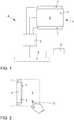
- the operating device 6 comprises a display device 1 with a display surface 2, which is arranged in the interior of the vehicle 10 so that it is clearly visible to at least one vehicle occupant, in particular the driver.
- the display surface 2 can be provided by a display, in particular a liquid crystal display, of any type.
- the operating device 6 further comprises a control device 3 and an input device.
- the control device 3 is connected to the display device 1, with which graphics data for displaying information on the display surface 2 can be generated.
- the input device is designed as a touch-sensitive surface 4 on the display surface 2. It is thus provided a so-called touch screen.
- a film may be arranged above the display surface 2, with which the position of a touch of an actuating object 13 can be detected.
- the actuating object is, in particular, the fingertip 13 of a user.
- the film can z. B. be formed as a resistive touch foil, capacitive touch foil or piezoelectric film. Further, the film may be formed so that a heat flow, the z. B. starting from the fingertip 13 of a user, is measured. From the temporal development of the contact of the film, various inputs can be obtained. For example, in the simplest case, the touching of the foil at a certain position can be detected and assigned to a graphic object displayed on the display surface 2. Furthermore, the length of the touch can be detected at a certain position or within a certain range. On the display surface 2 operable switching symbols, switching elements or buttons can be displayed.
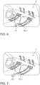
- the operating device 6 comprises an approach detection device 7.
- an actuation object 13 can be detected in a detection area 8.
- the detection area 8 is in Fig. 2 shown in detail.
- the detection area 8 is formed so that an approach of an operation object 13 to the touch-sensitive surface 4 on the display surface 2 is detected.
- the detection area 8 forms at least one volume in front of the touch-sensitive surface 4.
- a cuboid is formed which completely encloses the touch-sensitive surface 4 with its side surfaces in the extension which runs parallel to the touch-sensitive surface 4.
- the cuboid extends from the touch-sensitive surface 4 or immediately in front of the touch-sensitive surface 4 to a distance of z. B. about 40 cm.
- the distance of the outer boundary of the detection area 8 in front of the touch-sensitive surface 4 is chosen so that an approach to the touch-sensitive surface 4 can be detected in time so that the display on the display surface 2 can be changed soon enough to the user at a Input support.
- the distance of the detection area 8 from the touch-sensitive surface 4 should be selected so that the operation object 13 or another object is moved as rarely as possible into the detection area 8 when no operation of the touch-sensitive surface 4 is intended.
- the approach detection device 7 continuously transmits the current position of an operation object 13 in the detection area 8 to the control device 3.
- the control device 3 can change the display on the display surface 2.
- control device 3 is coupled to a data bus 5. Via this data bus 5, the control device 3 is connected to other devices of the vehicle 10, to which information is to be displayed on the display surface 2 and which are to be operated by means of the operating device 6. By means of operating device 6 and by the method information can be displayed to the vehicle occupants. Furthermore, the vehicle occupants can operate means of the vehicle 10 by means of the operating device 6 and control the display.
- the air conditioning device 9 of the vehicle 10 can be adjusted by means of the operating device 6.
- the air conditioning device 9 comprises ventilation elements 12-1 and 12-2, via which air can flow into the interior 11 of the vehicle 10.
- ventilation elements 12-1 and 12-2 By means of adjustment motors known per se for changing the position of the ventilation elements 12-1 and 12-2, the direction of the air flowing into the interior 11 of the vehicle 10 can be changed by means of the control device 3.
- the control device 3 Furthermore, by means of the control device 3, the inflow rate and the inflow temperature of the air flowing into the interior 11 through the ventilation elements 12-1 and 12-2 can be adjusted in a manner known per se.
- the air conditioning device 9 the temperature in the interior 11 of the vehicle 10 can be arbitrarily controlled. The temperature can be increased or decreased relative to the ambient temperature.
- FIGS. 4 to 9 an embodiment of the method according to the invention and the embodiment of the operating device 6 according to the invention, in particular the control device 3, explains:
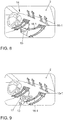
- FIG. 4 the display is shown on the display surface 2, which has been generated by the control device 3.
- the interior 11 of the vehicle 10 is reproduced by means of a perspective illustration 14.
- the viewer can quickly and intuitively recognize the physical elements of the interior 11 of the vehicle 10.
- the ventilation elements 12-1, 12-2 are visualized by means of the graphical objects 15-1 and 15-2.
- switching symbols 16-1 and 16-2 are displayed.
- Each switching symbol 16-1, 16-2 is assigned a separately adjustable ventilation element 12-1, 12-2. This is visualized by the proximity of the graphical representation of the switching symbols 16-1, 16-2 to corresponding graphical objects 15-1, 15-2 associated with the venting elements 12-1, 12-2.
- the switching symbols 16-1, 16-2 include arrow representations.
- the arrow of these arrow representations begins at the graphical object 15-1, 15-2 for the representation of the ventilation elements 12-1, 12-2 and shows in the flow direction the air flowing into the interior 11 of the vehicle 10 through the corresponding ventilation element 12-1 , 12-2 enters.
- the length of the arrow display visualizes the inflow rate.
- the inflow temperature of the air flowing into the interior through the ventilation elements 12-1, 12-2 can be visualized.
- FIG. 4 the display of the display area 2 is displayed in a display state when no operation is performed. If the user now enters the detection area 8 with his fingertip 13, this is detected by the proximity detection device 7. The control device 3 then changes the graphic data for the display on the display surface 2. After the user's fingertip 13 has entered the detection area 8, the in FIG. 5 shown display of the display surface 2 is displayed. This ad is different from the one in FIG. 4 display shown by the shift symbols 16-1, 16-2 are highlighted. The viewer can thus quickly and intuitively recognize which graphic objects displayed on the display area 2 are operated can. In FIG. 5 this emphasis is represented by a hatching of the switching symbols 16-1, 16-2. In the exemplary embodiment, however, the highlighting of these switching symbols 16 - 1, 16 - 2 can take place in various ways, for example by changing the color saturation, the transparency and / or the color of the switching symbols 16 - 1, 16 - 2.
- the control device 3 changes the graphic data for the display surface 2 so as to change the arrow shape of the switching symbol 16-1.
- the arrow follows the fingertip 13 of the user.
- the arrow display is thus longer. This is interpreted by the control device 3 as a control command for increasing the inflow rate from the associated venting element 12-1.
- the control device 3 generates a corresponding control signal for the air-conditioning device 9, which is transmitted to the same via the data bus 5.
- the user can reduce the arrow shape and reduce the inflow rate through the corresponding vent 12-1.
- the user can, starting from the in Fig. 6 illustrated situation, the inflow of the air change, which flows through a particular ventilation element 12-1, 12-2 in the interior 11 of the vehicle 10.
- a particular ventilation element 12-1, 12-2 in the interior 11 of the vehicle 10.
- the user moves his fingertip 13 on the touch-sensitive surface 4 to a position which in the perspective view 14 of the interior 11 of the vehicle desired inflow corresponds.
- the arrow display of the switching symbol 16-1 changes accordingly, as shown in FIG FIG. 8 is shown.
- the inflow rate can be changed by the user by the end position of the arrow of the switching symbol 16-1 determines the length of the arrow and the direction of the arrow. This is interpreted by the control device 3 as a corresponding control command for the inflow rate and the inflow direction, whereupon the control device 3 generates and transmits corresponding control signals for the air conditioning device 9.
- the user can also set the inflow temperature for the ventilation elements 12-1, 12-2 based on the symbols 16-1, 16-2.
- the user touches, for example with his fingertip 13, a specific switching symbol 16-1 for a certain time interval without moving the fingertip 13 on the touch-sensitive surface 4, as shown in FIG FIG. 9 is shown.
- graphic data is generated by the control device 3, which results in a switching element 17 being displayed for the temperature setting of the associated ventilation element 12-1.
- the current temperature of the air is displayed, which flows through the associated ventilation element 12-1 in the interior 11 of the vehicle 10.
- buttons for increasing and decreasing this temperature are shown.
- the user can generate control commands, which are converted by the control device 3 into control signals for raising and lowering the corresponding temperature and transmitted to the air-conditioning device 9.
- the switching element 17 can also be displayed permanently. Furthermore, it is possible that initially only the inflow temperature is displayed. When the user touches the touch-sensitive surface 4 with his fingertip 13 at a corresponding switching symbol 16-1, 16-2, the buttons for increasing or decreasing the corresponding inflow temperature are displayed.
Landscapes
- Engineering & Computer Science (AREA)
- Mechanical Engineering (AREA)
- Physics & Mathematics (AREA)
- Thermal Sciences (AREA)
- Chemical & Material Sciences (AREA)
- Combustion & Propulsion (AREA)
- Transportation (AREA)
- Air-Conditioning For Vehicles (AREA)
- User Interface Of Digital Computer (AREA)
Description
Die vorliegende Erfindung betrifft eine Bedienvorrichtung zum Einstellen einer Klimatisierungsvorrichtung eines Fahrzeugs. Die Klimatisierungsvorrichtung umfasst Belüftungselemente zum Klimatisieren des Innenraums des Fahrzeugs. Die Bedienvorrichtung weist eine Anzeigefläche und eine Eingabevorrichtung zum Eingeben von Steuerbefehlen für die Klimatisierungsvorrichtung des Fahrzeugs auf. Ferner umfasst die Bedienvorrichtung eine Steuervorrichtung, die mit der Anzeigefläche und der Eingabevorrichtung gekoppelt ist, mit der Graphikdaten für eine Anzeige auf der Anzeigefläche erzeugbar sind. Mit der Steuervorrichtung sind mittels der Eingabevorrichtung eingegebene Steuerbefehle in Steuersignale für die Klimatisierungsvorrichtung des Fahrzeugs umsetzbar. Des Weiteren betrifft die Erfindung ein Verfahren zum Einstellen einer Klimatisierungsvorrichtung eines Fahrzeugs.The present invention relates to an operating device for setting an air conditioning device of a vehicle. The air conditioning device comprises ventilation elements for conditioning the interior of the vehicle. The operating device has a display surface and an input device for inputting control commands for the air conditioning device of the vehicle. Furthermore, the operating device comprises a control device, which is coupled to the display surface and the input device with which graphics data can be generated for a display on the display surface. With the control device, control commands entered by means of the input device can be converted into control signals for the air conditioning device of the vehicle. Furthermore, the invention relates to a method for adjusting an air conditioning device of a vehicle.
In einem Kraftfahrzeug gibt es eine Vielzahl von Funktionseinrichtungen, die erforderlich sind, um das Fahrzeug zu führen, die der Sicherheit und dem Komfort der Fahrzeuginsassen dienen und die den Fahrzeuginsassen schließlich Informationen und Warnungen anzeigen. Außerdem dienen die Funktionseinrichtungen der Kommunikation der Fahrzeuginsassen mit außerhalb des Fahrzeugs angeordneten Einrichtungen. Zu diesen Funktionseinrichtungen zählen beispielsweise Einrichtungen zum Steuern der lichttechnischen Einrichtungen des Fahrzeugs, eine Klimatisierungsvorrichtung, Fahrerassistenzsysteme, Navigationssysteme, Telekommunikationssysteme und Multimediasysteme. Um diese Funktionseinrichtungen zu bedienen ist zumindest eine Vorrichtung für Eingaben des Nutzers und eine Anzeigevorrichtung zum Darstellen von Informationsanzeigen der Funktionseinrichtungen erforderlich. Ferner wird die Bedienung der Funktionseinrichtungen häufig von Anzeigen auf einem Display unterstützt, welches beispielsweise in der Mittelkonsole des Fahrzeugs angeordnet ist.In a motor vehicle, there are a variety of functional devices that are required to run the vehicle, which serve the safety and comfort of the vehicle occupants and finally display information and warnings to the vehicle occupants. In addition, the functional devices serve the communication of the vehicle occupants with arranged outside the vehicle facilities. These functional devices include, for example, devices for controlling the lighting equipment of the vehicle, an air conditioning device, driver assistance systems, navigation systems, telecommunication systems and multimedia systems. In order to operate these functional devices, at least one device for inputs of the user and a display device for displaying information displays of the functional devices are required. Furthermore, the operation of the functional devices is often supported by displays on a display, which is arranged for example in the center console of the vehicle.
Aus der
Aus der
Die
Die
Der vorliegenden Erfindung liegt daher die Aufgabe zugrunde, eine Bedienvorrichtung und ein Verfahren der eingangs genannten Art bereitzustellen, die eine einfache, schnelle und intuitive Einstellung der Klimatisierungsvorrichtung des Fahrzeugs erlauben.The present invention is therefore based on the object to provide an operating device and a method of the type mentioned, which allow a simple, quick and intuitive adjustment of the air conditioning device of the vehicle.
Erfindungsgemäß wird diese Aufgabe durch eine Bedienvorrichtung mit den Merkmalen des Anspruchs 1 und ein Verfahren mit den Merkmalen des Anspruchs 2 gelöst. Vorteilhafte Ausgestaltungen und Weiterbildungen ergeben sich aus den abhängigen Ansprüchen.According to the invention this object is achieved by an operating device having the features of
Die eingangs beschriebene Bedienvorrichtung ist dadurch gekennzeichnet, dass die Steuervorrichtung so ausgebildet ist, dass solche Graphikdaten erzeugt werden, dass auf der Anzeigefläche eine graphische Darstellung des Innenraums des Fahrzeugs wiedergegeben wird, wobei innerhalb der graphischen Darstellung des Innenraums des Fahrzeugs Schaltsymbole angezeigt werden, welche die Einströmrichtung und/oder die Einströmrate und/oder die Einströmtemperatur der durch die Belüftungselemente in den Innenraum einströmenden Luft darstellen. Ferner weist erfindungsgemäß die Eingabevorrichtung eine Erfassungseinrichtung auf, mittels welcher Eingaben eines Nutzers erfasst werden, die in Bezug auf die Schaltsymbole auf oder vor der Anzeigefläche ausgeführt werden.The operating device described above is characterized in that the control device is designed such that graphic data is generated such that a graphical representation of the interior of the vehicle is displayed on the display surface, wherein switching symbols are displayed within the graphical representation of the interior of the vehicle, which Inlet direction and / or the inflow rate and / or the inflow of the air flowing through the ventilation elements in the interior air. Furthermore, according to the invention, the input device has a detection device, by means of which inputs of a user which are executed with respect to the symbols on or in front of the display area.
Die erfindungsgemäße Bedienvorrichtung ermöglicht es insbesondere dem Fahrer des Fahrzeugs die Klimatisierungsvorrichtung schnell und intuitiv einzustellen. Durch die Darstellung des Innenraums des Fahrzeugs auf der Anzeigefläche der Bedienvorrichtung kann sich der Fahrer schnell orientieren. Innerhalb dieser graphischen Darstellung des Innenraums werden die Schaltsymbole zum Einstellen der Klimatisierungsvorrichtung angezeigt. Dies ermöglicht es dem Fahrer schnell und intuitiv einen Zusammenhang zwischen den Schaltsymbolen für die Einstellungen und den zugehörigen Belüftungselementen im Innenraum des Fahrzeugs herzustellen. Der Bedienvorgang selbst kann dann einfach und intuitiv anhand der Schaltsymbole ausgeführt werden. Der Nutzer muss sich also nicht merken, welche Bedienelemente zu welchen Belüftungselementen des Fahrzeugs gehören. Auch muss er nicht piktogrammartige Symbole interpretieren, da die angezeigten Schaltsymbole direkt zur Anzeige des Innenraums des Fahrzeugs korrespondieren.The operating device according to the invention makes it possible in particular for the driver of the vehicle to set the air conditioning device quickly and intuitively. The representation of the interior of the vehicle on the display surface of the operating device, the driver can quickly orientate. Within this graphic representation of the interior will be the switching symbols for setting the air conditioning device displayed. This allows the driver to quickly and intuitively establish a relationship between the switching symbols for the settings and the associated ventilation elements in the interior of the vehicle. The operation itself can then be carried out simply and intuitively by means of the switching symbols. The user therefore does not have to remember which operating elements belong to which ventilation elements of the vehicle. Also, it does not have to interpret pictogram-like symbols, since the displayed switching symbols correspond directly to the display of the interior of the vehicle.
Gemäß einer Ausgestaltung der erfindungsgemäßen Bedienvorrichtung umfasst die Eingabevorrichtung eine berührungsempfindliche Oberfläche, die auf der Anzeigefläche ausgebildet ist und auf der Eingaben ausführbar sind. Es wird somit ein sogenannter Touchscreen bereitgestellt. Die Verwendung eines Touchscreens als Eingabevorrichtung hat den Vorteil, dass keine oder nur eine geringe Anzahl an mechanischen Bedienelementen im Fahrzeuginnenraum angeordnet sein müssen. Ferner lässt sich ein Bedienkonzept, welches von einem Touchscreen unterstützt wird, sehr einfach an verschiedene Fahrzeugversionen anpassen.According to one embodiment of the operating device according to the invention, the input device comprises a touch-sensitive surface which is formed on the display surface and can be executed on the inputs. It is thus provided a so-called touch screen. The use of a touchscreen as an input device has the advantage that no or only a small number of mechanical operating elements must be arranged in the vehicle interior. Furthermore, an operating concept, which is supported by a touchscreen, can be easily adapted to different vehicle versions.
Ferner kann die Bedienvorrichtung eine Annäherungserfassungseinrichtung umfassen, mittels der eine Annäherung eines Betätigungsobjekts an die Anzeigefläche durch einen Eintritt des Betätigungsobjekts in einen Detektionsbereich vor der Anzeigefläche erfassbar ist. In Abhängigkeit von dem Erfassen des Eintritts des Betätigungsobjekts, wie beispielsweise der Hand oder der Fingerspitze eines Nutzers, in den Detektionsbereich kann die Anzeige auf der Anzeigefläche von der Steuervorrichtung verändert werden. Es können insbesondere die Schaltsymbole hervorgehoben dargestellt werden, damit der Nutzer schnell und intuitiv erkennt, welche graphische Elemente zum Einstellen der Klimatisierungsvorrichtung betätigbar sind.Furthermore, the operating device may comprise a proximity detection device, by means of which an approach of an actuating object to the display surface can be detected by an entry of the actuating object into a detection area in front of the display surface. Depending on the detection of the entry of the operating object, such as the hand or the fingertip of a user, into the detection area, the display on the display area can be changed by the control device. In particular, the switching symbols can be highlighted so that the user quickly and intuitively recognizes which graphical elements can be actuated to set the air conditioning device.
Die Annäherungserfassungseinrichtung kann beispielsweise eine Reflektionslichtschranke umfassen, die mindestens ein Leuchtmittel zum Emittieren von elektromagnetischer Detektionsstrahlung in den Detektionsbereich und ein Empfangselement zum Detektieren eines an dem Betätigungsobjekt gestreuten und/oder reflektierten Anteils der Detektionsstrahlung umfassen. Sie kann insbesondere so ausgebildet sein, das Betätigungsobjekt in dem Detektionsbereich anhand der Intensität der empfangenen Detektionsstrahlung zu erkennen. Die Annäherungserfassungseinrichtung kann ferner verschiedene Leuchtmittel für die einzelnen Detektionszonen umfassen, die jeweils elektromagnetische Detektionsstrahlung in die jeweilige Detektionszone emittieren. Des Weiteren kann eine Modulationsvorrichtung zum Modulieren der emittierten Detektionsstrahlung vorgesehen sein, so dass sich die Detektionsstrahlung, die in die einzelnen Detektionszonen emittiert wird, jeweils hinsichtlich ihrer Modulation unterscheidet. In diesem Fall kann die Annäherungserfassungseinrichtung auch eine Analyseeinheit umfassen, die so ausgebildet ist, dass die empfangene reflektierte und/oder gestreute Detektionsstrahlung hinsichtlich ihrer Modulation analysiert werden kann, um zu ermitteln, in welcher Detektionszone die Detektionsstrahlung an einem Betätigungsobjekt gestreut oder reflektiert wurde.The proximity detection device may, for example, comprise a reflection light barrier which comprises at least one light source for emitting electromagnetic detection radiation into the detection area and a reception element for detecting a portion of the detection radiation which is scattered and / or reflected by the actuation object. In particular, it can be designed to detect the actuation object in the detection area on the basis of the intensity of the received detection radiation. The proximity detection device may further comprise different illumination means for the individual detection zones, which each emit electromagnetic detection radiation into the respective detection zone. Furthermore, a modulation device may be provided for modulating the emitted detection radiation so that the detection radiation emitted into the individual detection zones differs in each case with regard to their modulation. In this case, the proximity detection device may also comprise an analysis unit which is designed so that the received reflected and / or scattered detection radiation can be analyzed for its modulation in order to determine in which detection zone the detection radiation was scattered or reflected on an actuating object.
Bei dem erfindungsgemäßen Verfahren zum Einstellen der Klimatisierungsvorrichtung des Fahrzeugs wird von einer Anzeigefläche eine graphische Darstellung des Innenraums des Fahrzeugs wiedergegeben. Beispielsweise kann diese graphische Darstellung den Innenraum des Fahrzeugs perspektivisch dreidimensional wiedergeben. Bei der graphischen Darstellung des Innenraums des Fahrzeugs werden ferner Schaltsymbole angezeigt, welche die Einströmrichtung und/oder die Einströmrate und/oder die Einströmtemperatur der durch Belüftungselemente in den Innenraum einströmenden Luft darstellen. Bei dem Verfahren wird eine Eingabe eines Nutzers erfasst, die in Bezug auf ein Schaltsymbol auf oder vor der Anzeigefläche ausgeführt wird. In Abhängigkeit von der Art der erfassten Eingabe und in Abhängigkeit davon, in Bezug zu welchem Schaltsymbol die Eingabe ausgeführt wurde, wird ein Steuerbefehl für die Klimatisierungsvorrichtung des Fahrzeugs erzeugt.In the method according to the invention for adjusting the air-conditioning device of the vehicle, a graphic display of the interior of the vehicle is reproduced by a display surface. For example, this graphical representation of the interior of the vehicle in perspective three-dimensional play. In the graphical representation of the interior of the vehicle, switching symbols are also displayed which represent the inflow direction and / or the inflow rate and / or the inflow temperature of the air flowing into the interior through ventilation elements. In the method, an input of a user that is executed with respect to a switching symbol on or in front of the display area is detected. Depending on the type of input detected and depending on which switching symbol the input has been made for, a control command is generated for the air conditioning device of the vehicle.
Das erfindungsgemäße Verfahren kann insbesondere von der vorstehend beschriebenen erfindungsgemäßen Bedienvorrichtung ausgeführt werden. Es weist somit dieselben Vorteile wie diese Bedienvorrichtung auf.The method according to the invention can be carried out in particular by the above-described operating device according to the invention. It thus has the same advantages as this operating device.
Gemäß dem erfindungsgemäßen Verfahren wird die Eingabe auf einer berührungsempfindlichen Oberfläche ausgeführt, die auf der Anzeigefläche ausgebildet ist. Dabei wird die Eingabe dadurch ausgeführt, dass die berührungsempfindliche Oberfläche bei einem Schaltsymbol mit einem Betätigungsobjekt berührt wird, daraufhin ein zu dem Schaltsymbol gehöriges Schaltelement angezeigt wird, welches vom Nutzer betätigt wird, woraufhin schließlich die Betätigung des Nutzers erfasst und in ein Steuerbefehl für die Klimatisierungsvorrichtung des Fahrzeugs umgesetzt wird. Durch diese Art der Eingabe auf der berührungsempfindlichen Oberfläche kann insbesondere die Einströmtemperatur der Luft eines bestimmten Belüftungselements im Innenraum des Fahrzeugs eingestellt werden. Hierfür zeigt beispielsweise das Schaltelement die aktuelle Einströmtemperatur des entsprechenden Belüftungselements an, sowie Schaltflächen zum Erhöhen und Erniedrigen dieser Einströmtemperatur.According to the method of the invention, the input is performed on a touch-sensitive surface formed on the display surface. The input is executed by the touch-sensitive Surface is touched when a switching icon with an actuating object, then a belonging to the switching symbol switching element is displayed, which is operated by the user, whereupon the operation of the user is detected and converted into a control command for the air conditioning device of the vehicle. By means of this type of input on the touch-sensitive surface, in particular the inflow temperature of the air of a specific ventilation element in the interior of the vehicle can be adjusted. For this purpose, for example, the switching element indicates the current inflow temperature of the corresponding ventilation element, as well as buttons for increasing and decreasing this inflow temperature.
Gemäß dem erfindungsgemäßen Verfahren wird die berührungsempfindliche Oberfläche bei einem Schaltsymbol mit einem Betätigungsobjekt berührt. Daraufhin wird das Betätigungsobjekt auf der berührungsempfindlichen Oberfläche bewegt. Anschließend wird die Berührung des Betätigungsobjekts von der berührungsempfindlichen Oberfläche wieder gelöst.According to the method of the invention, the touch-sensitive surface is touched on a switching symbol with an actuating object. Thereafter, the operation object is moved on the touch-sensitive surface. Subsequently, the touch of the actuating object is released from the touch-sensitive surface again.
Auf diese Weise kann beispielsweise die Einströmrichtung der durch die Belüftungselemente in den Innenraum einströmenden Luft eingestellt werden. Die Schaltsymbole umfassen in diesem Fall beispielsweise Pfeildarstellungen. Die berührungsempfindliche Oberfläche wird bei der Pfeildarstellung eines Schaltsymbols mit dem Betätigungsobjekt berührt. Daraufhin wird das Betätigungsobjekt auf der berührungsempfindlichen Oberfläche in Richtung der gewünschten Einströmrichtung bewegt. Anschließend wird die Berührung des Betätigungsobjekts von der berührungsempfindlichen Oberfläche wieder gelöst. Der Nutzer kann auf diese Weise mittels des Touchscreens die Pfeildarstellung verändern und hierdurch in der Darstellung des Innenraums des Fahrzeugs die Einströmrichtung für ein bestimmtes Belüftungselement einfach und intuitiv einstellen.In this way, for example, the inflow direction of the air flowing through the ventilation elements into the interior air can be adjusted. The switching symbols in this case comprise, for example, arrow representations. The touch-sensitive surface is touched when the arrow symbol of a switching symbol with the actuating object. Thereafter, the actuator is moved on the touch-sensitive surface in the direction of the desired inflow direction. Subsequently, the touch of the actuating object is released from the touch-sensitive surface again. In this way, the user can change the arrow display by means of the touch screen and thereby easily and intuitively set the inflow direction for a specific ventilation element in the representation of the interior of the vehicle.
Gleichermaßen kann auf diese Weise die Einströmrate der durch die Belüftungselemente in den Innenraum einströmenden Luft eingestellt werden. Auch in diesem Fall wird die berührungsempfindliche Oberfläche bei der Pfeildarstellung eines Schaltsymbols mit dem Betätigungsobjekt berührt. Das Betätigungsobjekt wird darauf auf der berührungsempfindlichen Oberfläche in Richtung des Pfeils oder in entgegengesetzte Richtung bewegt. Anschließend wird die Berührung des Betätigungsobjekts von der berührungsempfindlichen Oberfläche wieder gelöst. Der Nutzer kann hierdurch den Pfeil der Pfeildarstellung verlängern oder verkürzen und auf diese Weise die Einströmrate eines bestimmten Belüftungselements erhöhen oder erniedrigen. Auch dieser Bedienvorgang ist für den Nutzer sehr einfach und intuitiv durchführbar.Likewise, in this way the inflow rate of the air flowing through the ventilation elements into the interior can be adjusted. Also in this case, the touch-sensitive surface is touched in the arrow display of a switching symbol with the operation object. The actuator is then moved on the touch-sensitive surface in the direction of the arrow or in the opposite direction. Subsequently, the touch of the actuating object is released from the touch-sensitive surface again. The user can thereby extend or shorten the arrow of the arrow display and increase in this way the inflow rate of a particular ventilation element or humiliate. This operation is very simple and intuitive to the user.
Ferner kann durch einen einzigen Bedienvorgang sowohl die Einströmrichtung als auch die Einströmrate eines bestimmten Belüftungselements eingestellt werden, indem der Nutzer bei der Pfeildarstellung eines Schaltsymbols, welches zu einem bestimmten Betätigungsobjekt gehört, sowohl die Länge des Pfeils auch die Richtung des Pfeils durch eine Bewegung des Betätigungsobjekts auf der berührungsempfindlichen Oberfläche verändert. Auf diese Weise lassen sich verschiedene Parameter der Klimatisierungsvorrichtung des Fahrzeugs in einem einzigen Bedienvorgang schnell und intuitiv verändern.Furthermore, both the inflow and the inflow rate of a certain ventilation element can be adjusted by a single operation by the user in the arrow display of a switching symbol, which belongs to a specific actuation object, both the length of the arrow and the direction of the arrow by a movement of the actuation object changed on the touch-sensitive surface. In this way, various parameters of the air conditioning device of the vehicle can be changed quickly and intuitively in a single operation.
Ferner ist es möglich, dass eine Annäherung eines Betätigungsobjekts an die Anzeigefläche durch einen Eintritt des Betätigungsobjekts in einen Detektionsbereich vor der Anzeigefläche erfasst wird und, wenn der Eintritt des Betätigungsobjekts in den Detektionsbereich erfasst wurde, werden die Schaltsymbole verändert dargestellt. Hierdurch werden insbesondere die graphischen Elemente, welche auf der Anzeigefläche angezeigt werden, hervorgehoben, die bedienbar sind.Further, it is possible that an approach of an operation object to the display surface is detected by an entrance of the operation object into a detection area in front of the display area, and when the entry of the operation object into the detection area has been detected, the switching symbols are changed. As a result, in particular the graphic elements which are displayed on the display surface are highlighted, which are operable.
Unter einem Schaltsymbol, einem Schaltelement und einer Schaltfläche werden im Sinne der Erfindung Steuerelemente einer graphischen Benutzerschnittstelle verstanden. Ein Schaltsymbol, ein Schaltelement und eine Schaltfläche unterscheiden sich von Elementen und Flächen zur reinen Informationsanzeige, so genannten Anzeigeelementen bzw. Anzeigenflächen, darin, dass sie auswählbar sind. Bei einer Auswahl eines Schaltsymbols, eines Schaltelements und einer Schaltfläche wird eine zugeordnete Funktion ausgeführt. Die Funktion kann nur zu einer Veränderung der Informationsanzeige führen. Ferner können über das Schaltsymbol, das Schaltelement und die Schaltfläche Einrichtungen gesteuert werden, deren Bedienung von der Informationsanzeige unterstützt wird. Die Schaltsymbole, Schaltelemente und Schaltflächen können somit herkömmliche mechanische Schalter ersetzen. Sie können beliebig für eine frei programmierbaren Anzeigefläche erzeugt und von dieser angezeigt werden.For the purposes of the invention, a switching symbol, a switching element and a button are understood as meaning control elements of a graphical user interface. A switching symbol, a switching element and a button differ from elements and surfaces for purely information display, so-called display elements or advertising surfaces, in that they can be selected. Selecting a switching symbol, a switching element, and a button performs an associated function. The function can only change the information display. Furthermore, devices, the operation of which is supported by the information display, can be controlled via the switching symbol, the switching element and the button. The switching symbols, switching elements and buttons can thus replace conventional mechanical switches. They can be generated and displayed as desired for a freely programmable display area.
Des Weiteren betrifft die Erfindung ein Fahrzeug mit der erfindungsgemäßen Bedienvorrichtung. Die Anzeigefläche ist in diesem Fall so angeordnet, dass sie gut von dem Fahrer und/oder dem Beifahrer erreicht werden kann. Beispielsweise ist die Anzeigefläche in der Mittelkonsole des Fahrzeugs angeordnet.Furthermore, the invention relates to a vehicle with the operating device according to the invention. The display area is arranged in this case so that it can be easily reached by the driver and / or the passenger. For example, the display surface is arranged in the center console of the vehicle.
Die Erfindung wird nun anhand von Ausführungsbeispielen mit Bezug zu den Zeichnungen erläutert.
Figur 1- zeigt schematisch ein Ausführungsbeispiel der erfindungsgemäßen Bedienvorrichtung und die Kopplung der Bedienvorrichtung mit anderen Einrichtungen des Fahrzeugs,
Figur 2- zeigt eine Seitenansicht der Anzeigevorrichtung des Ausführungsbeispiels der Bedienvorrichtung zur Darstellung des Detektionsbereichs,
Figur 3- zeigt den Innenraum des Fahrzeugs, in welchem das Ausführungsbeispiel der erfindungsgemäßen Bedienvorrichtung untergebracht ist,
Figuren 4bis 9- zeigen Anzeigen, die auf der Anzeigefläche des Ausführungsbeispiels der erfindungsgemäßen Bedienvorrichtung angezeigt werden und die von einem Ausführungsbeispiel des erfindungsgemäßen Verfahrens erzeugt werden, und
- FIG. 1
- shows schematically an embodiment of the operating device according to the invention and the coupling of the operating device with other devices of the vehicle,
- FIG. 2
- shows a side view of the display device of the embodiment of the operating device for displaying the detection area,
- FIG. 3
- shows the interior of the vehicle, in which the embodiment of the operating device according to the invention is housed,
- FIGS. 4 to 9
- show displays which are displayed on the display surface of the embodiment of the operating device according to the invention and which are produced by an embodiment of the inventive method, and
Mit Bezug zu den
Die Bedienvorrichtung 6 umfasst eine Anzeigevorrichtung 1 mit einer Anzeigefläche 2, die so im Innenraum des Fahrzeugs 10 angeordnet ist, dass sie für zumindest einen Fahrzeuginsassen, insbesondere den Fahrer, gut sichtbar ist. Die Anzeigefläche 2 kann von einem Display, insbesondere einem Flüssigkeitskristalldisplay, beliebiger Bauart bereitgestellt werden.Related to the
The operating
Die Bedienvorrichtung 6 umfasst ferner eine Steuervorrichtung 3 und eine Eingabevorrichtung. Die Steuervorrichtung 3 ist mit der Anzeigevorrichtung 1 verbunden, mit welcher Graphikdaten zur Informationsdarstellung auf der Anzeigefläche 2 erzeugbar sind. Die Eingabevorrichtung ist als berührungsempfindliche Oberfläche 4 auf der Anzeigefläche 2 ausgebildet. Es wird somit ein sogenannter Touchscreen bereitgestellt.The operating
Beispielsweise kann eine Folie über der Anzeigefläche 2 angeordnet sein, mit welcher die Position einer Berührung eines Betätigungsobjekt 13 detektiert werden kann. Bei dem Betätigungsobjekt handelt es sich insbesondere um die Fingerspitze 13 eines Nutzers. Die Folie kann z. B. als resistive Touchfolie, kapazitive Touchfolie oder piezoelektrische Folie ausgebildet sein. Ferner kann die Folie so ausgebildet sein, dass ein Wärmestrom, der z. B. von der Fingerspitze 13 eines Nutzers ausgeht, gemessen wird. Aus der zeitlichen Entwicklung der Berührung der Folie lassen sich verschiedene Eingaben gewinnen. Beispielsweise kann im einfachsten Fall das Berühren der Folie bei einer bestimmten Position erfasst und einem auf der Anzeigefläche 2 angezeigten graphischen Objekt zugeordnet werden. Des Weiteren kann die Länge der Berührung bei einer bestimmten Position oder innerhalb eines bestimmten Bereichs erfasst werden. Auf der Anzeigefläche 2 können betätigbare Schaltsymbole, Schaltelemente oder Schaltflächen angezeigt werden.For example, a film may be arranged above the
Des Weiteren umfasst die Bedienvorrichtung 6 eine Annäherungserfassungseinrichtung 7. Mittels der Annäherungserfassungseinrichtung 7 kann ein Betätigungsobjekt 13 in einem Detektionsbereich 8 erfasst werden. Der Detektionsbereich 8 ist in
In dem hier beschriebenen Ausführungsbeispiel bildet der Detektionsbereich 8 zumindest ein Volumen vor der berührungsempfindliche Oberfläche 4. Es ist insbesondere ein Quader gebildet, der mit seinen Seitenflächen in der Erstreckung, die parallel zu der berührungsempfindlichen Oberfläche 4 verläuft, die berührungsempfindliche Oberfläche 4 vollständig umschließt. In einer Richtung senkrecht zur berührungsempfindlichen Oberfläche 4 reicht der Quader von der berührungsempfindlichen Oberfläche 4 oder unmittelbar vor der berührungsempfindlichen Oberfläche 4 bis zu einem Abstand von z. B. etwa 40 cm. Der Abstand der äußeren Grenze des Detektionsbereichs 8 vor der berührungsempfindlichen Oberfläche 4 wird dabei so gewählt, dass eine Annäherung an die berührungsempfindliche Oberfläche 4 so rechtzeitig detektiert werden kann, dass die Anzeige auf der Anzeigefläche 2 früh genug verändert werden kann, um den Nutzer bei einer Eingabe zu unterstützen. Ferner sollte der Abstand des Detektionsbereichs 8 von der berührungsempfindlichen Oberfläche 4 so gewählt werden, dass das Betätigungsobjekt 13 oder ein anderes Objekt so selten wie möglich in den Detektionsbereich 8 bewegt wird, wenn keine Bedienung der berührungsempfindlichen Oberfläche 4 beabsichtigt ist.In the exemplary embodiment described here, the
Weitere Details zu verschiedenen Ausbildungen der Annäherungserfassungseinrichtung 7 sind beispielsweise in der
Die Annäherungserfassungseinrichtung 7 überträgt die aktuelle Position eines Betätigungsobjekts 13 im Detektionsbereich 8 fortwährend an die Steuervorrichtung 3. In Abhängigkeit von diesem Signal kann die Steuervorrichtung 3 die Anzeige auf der Anzeigefläche 2 verändern.The
Schließlich ist die Steuervorrichtung 3 mit einem Datenbus 5 gekoppelt. Über diesen Datenbus 5 ist die Steuervorrichtung 3 mit weiteren Einrichtungen des Fahrzeugs 10 verbunden, zu denen Informationen auf der Anzeigefläche 2 angezeigt werden sollen und die mittels der Bedienvorrichtung 6 bedient werden sollen. Mittels Bedienvorrichtung 6 und durch das Verfahren können den Fahrzeuginsassen Informationen angezeigt werden. Ferner können die Fahrzeuginsassen mittels der Bedienvorrichtung 6 Einrichtungen des Fahrzeugs 10 bedienen und die Anzeige steuern.Finally, the
Im vorliegenden Ausführungsbeispiel kann mittels der Bedienvorrichtung 6 die Klimatisierungsvorrichtung 9 des Fahrzeugs 10 eingestellt werden. Die Klimatisierungsvorrichtung 9 umfasst Belüftungselemente 12-1 und 12-2, über welche Luft in den Innenraum 11 des Fahrzeugs 10 einströmen kann. Mittels an sich bekannter Einstellmotoren zur Lageveränderung der Belüftungselemente 12-1 und 12-2 kann mittels der Steuervorrichtung 3 die Richtung der in den Innenraum 11 des Fahrzeugs 10 einströmenden Luft verändert werden. Ferner kann mittels der Steuervorrichtung 3 auf an sich bekannte Weise die Einströmrate und die Einströmtemperatur der durch die Belüftungselemente 12-1 und 12-2 in den Innenraum 11 einströmenden Luft eingestellt werden. Durch die Klimatisierungsvorrichtung 9 kann die Temperatur im Innenraum 11 des Fahrzeugs 10 beliebig geregelt werden. Die Temperatur kann dabei relativ zur Umgebungstemperatur erhöht oder erniedrigt werden.In the present embodiment, the
Im Folgenden wird mit Bezug zu den
In
In
Zusätzlich zu der graphischen Darstellung 14 des Innenraums 11 werden Schaltsymbole 16-1 und 16-2 angezeigt.In addition to the
Jedem Schaltsymbol 16-1, 16-2 ist dabei ein separat einstellbares Belüftungselement 12-1, 12-2 zugeordnet. Dies wird durch die Nähe der graphischen Darstellung der Schaltsymbole 16-1, 16-2 zu entsprechenden graphischen Objekten 15-1, 15-2 visualisiert, die den Belüftungselementen 12-1, 12-2 zugeordnet sind.Each switching symbol 16-1, 16-2 is assigned a separately adjustable ventilation element 12-1, 12-2. This is visualized by the proximity of the graphical representation of the switching symbols 16-1, 16-2 to corresponding graphical objects 15-1, 15-2 associated with the venting elements 12-1, 12-2.
Die Schaltsymbole 16-1, 16-2 umfassen Pfeildarstellungen. Der Pfeil dieser Pfeildarstellungen beginnt bei dem graphischen Objekt 15-1, 15-2 für die Darstellung der Belüftungselemente 12-1, 12-2 und zeigt in Strömungsrichtung die Luft, die in den Innenraum 11 des Fahrzeugs 10 durch das entsprechende Belüftungselement 12-1, 12-2 eintritt. Die Länge der Pfeildarstellung visualisiert die Einströmrate. Ferner kann durch die Wahl der Farbe bei der Darstellung der Schaltsymbole 16-1, 16-2 die Einströmtemperatur der durch die Belüftungselemente 12-1, 12-2 in den Innenraum einströmenden Luft visualisiert werden.The switching symbols 16-1, 16-2 include arrow representations. The arrow of these arrow representations begins at the graphical object 15-1, 15-2 for the representation of the ventilation elements 12-1, 12-2 and shows in the flow direction the air flowing into the interior 11 of the
In
Wenn der Nutzer nun einen Parameter eines Belüftungselements 12-1 bzw. 12-2 der Klimatisierungsvorrichtung 9 verändern will, berührt er mit der Fingerspitze 13 die berührungsempfindliche Oberfläche 4 bei dem Schaltsymbol 16-1, welches dem graphischen Objekt 15-1 zugeordnet ist, welches wiederum dem Belüftungselement 12-1 zugeordnet ist, welches der Nutzer verstellen will, wie es in
Wenn der Nutzer nun die Einströmrate dieses Belüftungselements 12-1 vergrößern will, bewegt er die Fingerspitze 13 auf der berührungsempfindlichen Oberfläche 4 in Richtung des Pfeils des Schaltsymbols 16-1. Diese Bewegung auf der berührungsempfindlichen Oberfläche 4 wird von der Steuervorrichtung 3 erfasst. Im Wesentlichen gleichzeitig mit dem Erfassen dieser Bewegung auf der berührungsempfindlichen Oberfläche 4, verändert die Steuervorrichtung 3 die Graphikdaten für die Anzeigefläche 2 so, dass die Pfeildarstellung des Schaltsymbols 16-1 verändert wird. Der Pfeil folgt der Fingerspitze 13 des Nutzers. Die Pfeildarstellung wird somit länger. Dies interpretiert die Steuervorrichtung 3 als Steuerbefehl zum Erhöhen der Einströmrate aus dem zugeordneten Belüftungselement 12-1. Die Steuervorrichtung 3 erzeugt ein entsprechendes Steuersignal für die Klimatisierungsvorrichtung 9, welches derselben über den Datenbus 5 übertragen wird. Wenn der Nutzer durch Ziehen seiner Fingerspitze 13 auf der berührungsempfindlichen Oberfläche 4 die gewünschte Einströmrate erreicht hat, löst er die Fingerspitze 13 wieder von der berührungsempfindlichen Oberfläche 4. Es verbleibt ein verlängerter Pfeil des Schaltsymbols 16-1, welcher die erhöhte Einströmrate durch das zugeordnete Belüftungselement 12-1 visualisiert.If the user now wants to increase the inflow rate of this ventilation element 12-1, he moves the
Auf analoge Weise kann der Nutzer durch die Bewegung seiner Fingerspitze 13 auf der berührungsempfindlichen Oberfläche 4 in entgegengesetzter Richtung die Pfeildarstellung verkleinern und die Einströmrate durch das entsprechende Belüftungselement 12-1 verringern.Similarly, by moving his
Des Weiteren kann der Nutzer ausgehend von der in
Gemeinsam mit der Einströmrichtung kann auch die Einströmrate verändert werden, indem der Nutzer durch die Endposition des Pfeils des Schaltsymbols 16-1 die Länge des Pfeils und die Richtung des Pfeils festlegt. Dies wird von der Steuervorrichtung 3 als entsprechender Steuerbefehl für die Einströmrate und die Einströmrichtung interpretiert, woraufhin die Steuervorrichtung 3 entsprechende Steuersignale für die Klimatisierungsvorrichtung 9 erzeugt und an dieselbe überträgt.Together with the inflow direction, the inflow rate can be changed by the user by the end position of the arrow of the switching symbol 16-1 determines the length of the arrow and the direction of the arrow. This is interpreted by the
Schließlich kann der Nutzer anhand der Schaltsymbole 16-1, 16-2 auch die Einströmtemperatur für die Belüftungselemente 12-1, 12-2 einstellen. Hierfür berührt der Nutzer beispielsweise mit seiner Fingerspitze 13 ein bestimmtes Schaltsymbol 16-1 für ein bestimmtes Zeitintervall ohne die Fingerspitze 13 auf der berührungsempfindlichen Oberfläche 4 zu bewegen, wie dies in
Alternativ oder zusätzlich kann das Schaltelement 17 auch dauerhaft angezeigt werden. Ferner wäre es möglich, dass zunächst nur die Einströmtemperatur angezeigt wird. Wenn der Nutzer die berührungsempfindliche Oberfläche 4 mit seiner Fingerspitze 13 bei einem entsprechenden Schaltsymbol 16-1, 16-2 berührt, werden die Schaltflächen zum Erhöhen oder Erniedrigen der entsprechenden Einströmtemperatur eingeblendet.Alternatively or additionally, the switching
- 11
- Anzeigevorrichtungdisplay device
- 22
- Anzeigeflächedisplay area
- 33
- Steuervorrichtungcontrol device
- 44
- berührungsempfindliche Oberfläche, Eingabevorrichtungtouch-sensitive surface, input device
- 55
- Datenbusbus
- 66
- Bedienvorrichtungoperating device
- 77
- AnnäherungserfassungseinrichtungApproach detection device
- 88th
- Detektionsbereichdetection range
- 99
- KlimatisierungsvorrichtungAir conditioning device
- 1010
- Fahrzeugvehicle
- 1111
- Innenraum des FahrzeugsInterior of the vehicle
- 12-1, 12-212-1, 12-2
- Belüftungselementeventilation elements
- 1313
- Fingerspitze der Hand eines NutzersFingertip of a user's hand
- 1414
- perspektivische graphische Darstellung des Innenraums des Fahrzeugsperspective graphic representation of the interior of the vehicle
- 15-1, 15-215-1, 15-2
- graphische Objekte zur Darstellung der Belüftungselementegraphical objects for displaying the ventilation elements
- 16-1, 16-216-1, 16-2
- Schaltsymbolesymbols
- 1717
- Schaltelementswitching element
Claims (6)
- An operating device (6) for adjusting an air conditioning device (9) of a vehicle (10), which comprises air ventilation elements (12-1, 12-2) for air-conditioning the interior (11) of the vehicle (10), having- a display surface (2),- an input device (4) for entering control commands for the air conditioning device (9) of the vehicle (10), and- a control device (3), which is coupled to the display surface (2) and to the input device (4), with which graphic data for a display on the display surface (2) can be generated and with which control commands entered by means of the input device (4) can be converted into control signals for the air conditioning device (9) of the vehicle 10), wherein- the control device (3) is designed such that such graphic data are generated, that a graphic representation (14) of the interior (11) of the vehicle (10) is depicted on the display surface (2) with graphic objects (15-1, 15-2) which are associated with the ventilation elements (12-1, 12-2), wherein within the graphic representation (14) of the interior (11) of the vehicle (10) switching symbols (16-1, 16-2) are displayed, which represent the inflow direction and/or the inflow rate and/or the inflow temperature of the air flowing into the interior (11) through the ventilation elements (12-1, 12-2),- to each switching symbol (16-1, 16-2) a separately adjustable ventilation element (12-1, 12-2) is assigned, which is visualized by the proximity of the graphic representation of the switching symbols (16-1, 16-2) to the corresponding graphic objects (15-1, 15-2),- the input device (4) has a detection device (4; 18), by means of which a user's inputs are detected, which are performed with respect to the switching symbols (16-1, 16-2) on or in front of the display device (2), and- the input device (4) comprises a touch-sensitive surface (4), which is formed on the display surface (2) and on which inputs can be performed,characterized in that
the inputs can be performed on a touch-sensitive surface (4), which is formed on the display surface, in that the touch-sensitive surface (4) in the case of a switching symbol (16-1, 16-2) is touched with an actuating object (13), which actuating object (13) thereupon is moved on the touch-sensitive surface (4) and subsequently the contact of the actuating object (13) is released again from the touch-sensitive surface (4). - A method for adjusting an air conditioning device (9) of a vehicle (10), in which- a graphic representation (14) of the interior (11) of the vehicle (10) is depicted by the display surface (2) with graphic objects (15-1, 15-2), which are associated with the ventilation elements (12-1, 12-2), in which switching symbols (16-1, 16-2) are displayed, which represent the inflow direction and/or the inflow rate and/or the inflow temperature of the air flowing into the interior (11) through the ventilation elements (12-1, 12-2),- wherein to each switching symbol (16-1, 16-2) a separately adjustable ventilation element (12-1, 12-2) is assigned, which is visualized by the proximity of the graphic representation of the switching symbols (16-1, 16-2) to the corresponding graphic objects (15-1, 15-2),- an input of a user is detected, which is performed with respect to the switching symbols (16-1, 16-2) on or in front of the display device (2), wherein the input is performed on a touch-sensitive surface (4), which is formed on the display surface, in that the touch-sensitive surface (4) is touched in the case of a switching symbol (16-1, 16-2) with an actuating object (13), which actuating object (13) is thereupon moved on the touch-sensitive surface (4) and subsequently the contact of the actuating object (13) is released again from the touch-sensitive surface (4), and- depending on the type of the input detected and depending on, in respect to which switching symbol (16-1, 16-2) the input was performed, a control command is generated for the air conditioning device (9) of the vehicle.
- The method according to Claim 2,
characterized in
that the input is performed on a touch-sensitive surface (4), which is formed on the display surface (2) in that the touch-sensitive surface (4) is touched in the case of a switching symbol (16-1, 16-2) with an actuating object (13), thereupon a switching element(17) belonging to the switching symbol (16-1, 16-2) is displayed, which is actuated by the user, which actuation of the user is detected and is converted into a control command for the air conditioning device (9) of the vehicle (10). - The method according to Claim 2 or 3,
characterized in
that the switching symbols (16-1, 16-2) comprise arrow representations and to adjust the inflow rate of the air flowing into the interior (11) through the ventilation elements (12-1, 12-2) the touch-sensitive surface (4) is touched in the case of the arrow representation of a switching symbol (16-1, 16-2) with the actuating object (13), which actuating object (13) is thereupon moved on the touch-sensitive surface (4) in the direction of the desired inflow direction and subsequently the contact of the actuating object (13) is released again from the touch-sensitive surface (4). - The method according to any one of Claims 2 to 4,
characterized in
that the switching symbols (16-1, 16-2) comprise arrow representations and to adjust the inflow direction of the air flowing into the interior (11) through the ventilation elements (12-1, 12-2) the touch-sensitive surface (4) is touched in the case of the arrow representation of a switching symbol (16-1, 16-2) with the actuating object (13), which actuating object (13) is thereupon moved on the touch-sensitive surface (4) in the direction of the arrow or in the opposite direction and subsequently the contact of the actuating object (13) is released again from the touch-sensitive surface (4). - The method according to any one of Claims 2 to 5,
characterized in
that an approach of an actuating object (13) to the display surface (2) is detected by the entry of the actuating object (13) into a detection region (8) in front of the display surface (2) and, if the entry of the actuating object (123) into the detection region (8) was detected, the switching symbols (16-1, 16-2) are represented changed.
Applications Claiming Priority (2)
| Application Number | Priority Date | Filing Date | Title |
|---|---|---|---|
| DE102012016109.3A DE102012016109A1 (en) | 2012-08-15 | 2012-08-15 | Operating device for setting an air conditioning device of a vehicle and method thereof |
| PCT/EP2013/066195 WO2014026854A1 (en) | 2012-08-15 | 2013-08-01 | Operating device for adjusting an air conditioning device of a vehicle and corresponding method |
Publications (2)
| Publication Number | Publication Date |
|---|---|
| EP2885142A1 EP2885142A1 (en) | 2015-06-24 |
| EP2885142B1 true EP2885142B1 (en) | 2019-11-13 |
Family
ID=48914299
Family Applications (1)
| Application Number | Title | Priority Date | Filing Date |
|---|---|---|---|
| EP13744556.5A Active EP2885142B1 (en) | 2012-08-15 | 2013-08-01 | Operating device for adjusting an air conditioning device of a vehicle and corresponding method |
Country Status (6)
| Country | Link |
|---|---|
| EP (1) | EP2885142B1 (en) |
| KR (1) | KR101701017B1 (en) |
| CN (1) | CN104540695B (en) |
| DE (1) | DE102012016109A1 (en) |
| ES (1) | ES2764380T3 (en) |
| WO (1) | WO2014026854A1 (en) |
Cited By (1)
| Publication number | Priority date | Publication date | Assignee | Title |
|---|---|---|---|---|
| US20210039473A1 (en) * | 2019-08-05 | 2021-02-11 | Hyundai Motor Company | Vehicle and Control Method of Vehicle |
Families Citing this family (22)
| Publication number | Priority date | Publication date | Assignee | Title |
|---|---|---|---|---|
| CN105144070B (en) * | 2014-03-03 | 2018-04-13 | 大众汽车有限公司 | Method and apparatus for providing graphic user interface in the car |
| DE102014207383A1 (en) * | 2014-04-17 | 2015-10-22 | Bayerische Motoren Werke Aktiengesellschaft | Operation of an air conditioning system for the interior of a motor vehicle |
| DE102015202414B4 (en) * | 2015-02-11 | 2021-04-22 | Volkswagen Aktiengesellschaft | Method for adapting a setting of a heating / air conditioning function for a means of transport |
| US9840128B2 (en) | 2015-03-10 | 2017-12-12 | Ford Global Technologies, Llc | Vent adjusting system |
| DE102015204380A1 (en) * | 2015-03-11 | 2016-09-15 | Volkswagen Aktiengesellschaft | Means of transport, user interface and method for operating a heating air conditioning of a means of transport |
| JP6443188B2 (en) * | 2015-04-02 | 2018-12-26 | 株式会社デンソー | Display device for vehicle air conditioning |
| DE102015207975A1 (en) | 2015-04-30 | 2016-11-03 | Volkswagen Aktiengesellschaft | Method and operating device for setting an air conditioning device of a vehicle |
| DE102015209860A1 (en) | 2015-05-28 | 2016-12-01 | Volkswagen Aktiengesellschaft | Method for visualizing ventilation flows and sound waves in a vehicle |
| DE102015222039B4 (en) * | 2015-11-10 | 2020-11-19 | Volkswagen Aktiengesellschaft | Method and system for operating a ventilation device in a vehicle |
| JP6597506B2 (en) * | 2016-07-19 | 2019-10-30 | 株式会社デンソー | Vehicle control device |
| DE102016114354A1 (en) * | 2016-08-03 | 2018-02-08 | Volkswagen Ag | Method and operating device for operating an air conditioning device of a vehicle |
| KR20180062883A (en) * | 2016-12-01 | 2018-06-11 | 이래오토모티브시스템 주식회사 | Apparatus and user interface for infotainment |
| DE102017212056A1 (en) * | 2017-07-13 | 2019-01-17 | Zf Friedrichshafen Ag | Operating device for operating a touch-sensitive surface for a vehicle, surface control device with an operating device and method and control device for operating a touch-sensitive surface by means of an operating device |
| DE102018205690A1 (en) * | 2018-04-13 | 2019-10-17 | Bayerische Motoren Werke Aktiengesellschaft | Method and system for controlling a user interface and an air conditioning unit |
| DE102018222124A1 (en) * | 2018-12-18 | 2020-06-18 | Volkswagen Aktiengesellschaft | Method and system for setting a value of a parameter |
| JP7052712B2 (en) * | 2018-12-27 | 2022-04-12 | 株式会社Jvcケンウッド | Display device |
| DE102019105121A1 (en) * | 2019-02-28 | 2020-09-03 | Bayerische Motoren Werke Aktiengesellschaft | Vehicle interior ventilation system and vehicle |
| KR102316921B1 (en) * | 2019-04-26 | 2021-10-25 | 한국아이티더블유 유한책임회사 | Method and apparatus for controlling airvent through display device |
| DE102019218405A1 (en) * | 2019-11-27 | 2021-05-27 | Faurecia Innenraum Systeme Gmbh | AIR FLOW CONTROL UNIT AND A METHOD OF REGULATING AN AIR FLOW |
| ES2930480A1 (en) * | 2021-06-08 | 2022-12-13 | Seat Sa | SYSTEM, METHOD AND COMPUTER PROGRAM FOR THE CONTROL OF AN AIR EXHAUST DEVICE (Machine-translation by Google Translate, not legally binding) |
| DE102022203784A1 (en) | 2022-04-14 | 2023-10-19 | Psa Automobiles Sa | User interface of a vehicle |
| WO2023247505A1 (en) * | 2022-06-21 | 2023-12-28 | Jaguar Land Rover Limited | Climate controller and climate control method |
Family Cites Families (8)
| Publication number | Priority date | Publication date | Assignee | Title |
|---|---|---|---|---|
| JPS6422619A (en) * | 1987-07-16 | 1989-01-25 | Diesel Kiki Co | Air-conditioning display control for vehicle |
| ES2194623T3 (en) | 2001-09-11 | 2006-02-16 | TRW AUTOMOTIVE ELECTRONICS & COMPONENTS GMBH & CO. KG | REGULATION SYSTEM FOR A VEHICLE AIR CONDITIONING DEVICE. |
| JP2003211944A (en) * | 2002-01-18 | 2003-07-30 | Tokai Rika Co Ltd | Display device for air conditioner |
| DE102007023502A1 (en) * | 2006-05-23 | 2007-12-06 | Wolfgang Kirchner | Display/operating unit for vehicle, heating or air conditioning system displays status of temperature, air feed and air speed automatically set by air conditioning system in three cells of person symbol, seat symbol divided into two regions |
| DE102009011709A1 (en) | 2009-03-09 | 2010-09-16 | Volkswagen Ag | Instrument panel with a display and control component |
| DE102009051202A1 (en) | 2009-10-29 | 2011-05-12 | Volkswagen Ag | Method for operating an operating device and operating device |
| DE102010011039A1 (en) * | 2010-03-11 | 2011-09-15 | Volkswagen Ag | Method and device for operating a user interface |
| KR101695644B1 (en) * | 2010-08-27 | 2017-01-12 | 한온시스템 주식회사 | Controller of Air conditioner in vehicle |
-
2012
- 2012-08-15 DE DE102012016109.3A patent/DE102012016109A1/en not_active Withdrawn
-
2013
- 2013-08-01 CN CN201380043582.5A patent/CN104540695B/en active Active
- 2013-08-01 KR KR1020147035897A patent/KR101701017B1/en active IP Right Grant
- 2013-08-01 WO PCT/EP2013/066195 patent/WO2014026854A1/en active Application Filing
- 2013-08-01 EP EP13744556.5A patent/EP2885142B1/en active Active
- 2013-08-01 ES ES13744556T patent/ES2764380T3/en active Active
Non-Patent Citations (1)
| Title |
|---|
| None * |
Cited By (2)
| Publication number | Priority date | Publication date | Assignee | Title |
|---|---|---|---|---|
| US20210039473A1 (en) * | 2019-08-05 | 2021-02-11 | Hyundai Motor Company | Vehicle and Control Method of Vehicle |
| US11590823B2 (en) * | 2019-08-05 | 2023-02-28 | Hyundai Motor Company | Vehicle and control method of vehicle |
Also Published As
| Publication number | Publication date |
|---|---|
| CN104540695B (en) | 2017-06-13 |
| ES2764380T3 (en) | 2020-06-03 |
| WO2014026854A1 (en) | 2014-02-20 |
| EP2885142A1 (en) | 2015-06-24 |
| CN104540695A (en) | 2015-04-22 |
| KR20150020225A (en) | 2015-02-25 |
| KR101701017B1 (en) | 2017-01-31 |
| DE102012016109A1 (en) | 2014-02-20 |
Similar Documents
| Publication | Publication Date | Title |
|---|---|---|
| EP2885142B1 (en) | Operating device for adjusting an air conditioning device of a vehicle and corresponding method | |
| EP3040245B1 (en) | Device and method for supporting a user before operation of a switch for electromotive adjustment of a part of a means of locomotion | |
| EP2493718B1 (en) | Method for operating a control device, and control device | |
| EP3484738B1 (en) | Vehicle having an operator control and display device and method for operating such a vehicle | |
| EP3114554B1 (en) | Method and apparatus for providing a graphical user interface in a vehicle | |
| EP3237250B1 (en) | Finger-operated control bar, and use of said control bar | |
| EP3279018B1 (en) | Method and operating device for operating an air conditioning device of a vehicle | |
| DE102015005126B3 (en) | Method and operating device for operating an air conditioning system of a vehicle | |
| EP3508967B1 (en) | Human-machine interface and method for operating a human-machine interface | |
| EP3508968A1 (en) | Human-machine interface and method for operating a human-machine interface | |
| DE102015011650B4 (en) | Motor vehicle operating device with touchscreen operation | |
| DE102013009603A1 (en) | Method for achieving a desired comfort setting in a motor vehicle and device for carrying out the method | |
| DE102014011118B4 (en) | Method for operating a light function of motor vehicle headlights and motor vehicle with a display device and a control element for operating the light function of the motor vehicle headlights | |
| EP3088220B1 (en) | Method and operating device for adjusting an air conditioning device of a vehicle | |
| DE102010018140A1 (en) | Temperature adjusting device for air conditioning apparatus of motor car, for heating e.g. driver seat, has display integrated into housing for displaying variable information, where keys and rotary knobs are integrated into housing | |
| DE102016207611B4 (en) | Display and operating system | |
| DE102019218386B4 (en) | Method and device for adjusting a position of an adjustable vehicle part | |
| EP2885153B1 (en) | Method for providing an operating device in a vehicle and operating device for a vehicle | |
| WO2018002262A1 (en) | Method and device for controlling the air-conditioning function of a vehicle seat | |
| DE102015225248B4 (en) | System for acquiring a value for one of at least two setting parameters of a motor vehicle | |
| EP3067227B1 (en) | Means of locomotion, user interface and method for operating a heating air conditioner of a means of locomotion | |
| DE102014014336A1 (en) | Operating device for a motor vehicle | |
| EP3102453B1 (en) | Method and device for indicating a change to a setting of at least one parameter of a vehicle function | |
| DE102021207897A1 (en) | Operating unit for the exterior mirrors of a vehicle | |
| WO2013113731A1 (en) | Method for producing an operating device in a vehicle and operating device for a vehicle |
Legal Events
| Date | Code | Title | Description |
|---|---|---|---|
| PUAI | Public reference made under article 153(3) epc to a published international application that has entered the european phase |
Free format text: ORIGINAL CODE: 0009012 |
|
| 17P | Request for examination filed |
Effective date: 20150316 |
|
| AK | Designated contracting states |
Kind code of ref document: A1 Designated state(s): AL AT BE BG CH CY CZ DE DK EE ES FI FR GB GR HR HU IE IS IT LI LT LU LV MC MK MT NL NO PL PT RO RS SE SI SK SM TR |
|
| AX | Request for extension of the european patent |
Extension state: BA ME |
|
| RIN1 | Information on inventor provided before grant (corrected) |
Inventor name: KUHN, MATHIAS Inventor name: BUDZYNSKI, TOBIAS Inventor name: JUN, MI-RAN Inventor name: PETERSEN, SOENKE |
|
| RIN1 | Information on inventor provided before grant (corrected) |
Inventor name: KUHN, MATHIAS Inventor name: BUDZYNSKI, TOBIAS Inventor name: PETERSEN, SOENKE Inventor name: JUN, MI-RAN |
|
| DAX | Request for extension of the european patent (deleted) | ||
| STAA | Information on the status of an ep patent application or granted ep patent |
Free format text: STATUS: EXAMINATION IS IN PROGRESS |
|
| 17Q | First examination report despatched |
Effective date: 20171103 |
|
| REG | Reference to a national code |
Ref country code: DE Ref legal event code: R079 Ref document number: 502013013901 Country of ref document: DE Free format text: PREVIOUS MAIN CLASS: B60H0001000000 Ipc: B60K0035000000 |
|
| RIC1 | Information provided on ipc code assigned before grant |
Ipc: B60K 35/00 20060101AFI20190724BHEP Ipc: B60H 1/00 20060101ALI20190724BHEP Ipc: B60K 37/06 20060101ALI20190724BHEP |
|
| GRAP | Despatch of communication of intention to grant a patent |
Free format text: ORIGINAL CODE: EPIDOSNIGR1 |
|
| STAA | Information on the status of an ep patent application or granted ep patent |
Free format text: STATUS: GRANT OF PATENT IS INTENDED |
|
| GRAS | Grant fee paid |
Free format text: ORIGINAL CODE: EPIDOSNIGR3 |
|
| INTG | Intention to grant announced |
Effective date: 20190912 |
|
| GRAA | (expected) grant |
Free format text: ORIGINAL CODE: 0009210 |
|
| STAA | Information on the status of an ep patent application or granted ep patent |
Free format text: STATUS: THE PATENT HAS BEEN GRANTED |
|
| AK | Designated contracting states |
Kind code of ref document: B1 Designated state(s): AL AT BE BG CH CY CZ DE DK EE ES FI FR GB GR HR HU IE IS IT LI LT LU LV MC MK MT NL NO PL PT RO RS SE SI SK SM TR |
|
| REG | Reference to a national code |
Ref country code: CH Ref legal event code: EP Ref country code: AT Ref legal event code: REF Ref document number: 1201306 Country of ref document: AT Kind code of ref document: T Effective date: 20191115 |
|
| REG | Reference to a national code |
Ref country code: DE Ref legal event code: R096 Ref document number: 502013013901 Country of ref document: DE |
|
| REG | Reference to a national code |
Ref country code: IE Ref legal event code: FG4D Free format text: LANGUAGE OF EP DOCUMENT: GERMAN |
|
| REG | Reference to a national code |
Ref country code: NL Ref legal event code: MP Effective date: 20191113 |
|
| REG | Reference to a national code |
Ref country code: LT Ref legal event code: MG4D |
|
| PG25 | Lapsed in a contracting state [announced via postgrant information from national office to epo] |
Ref country code: NL Free format text: LAPSE BECAUSE OF FAILURE TO SUBMIT A TRANSLATION OF THE DESCRIPTION OR TO PAY THE FEE WITHIN THE PRESCRIBED TIME-LIMIT Effective date: 20191113 Ref country code: PL Free format text: LAPSE BECAUSE OF FAILURE TO SUBMIT A TRANSLATION OF THE DESCRIPTION OR TO PAY THE FEE WITHIN THE PRESCRIBED TIME-LIMIT Effective date: 20191113 Ref country code: LT Free format text: LAPSE BECAUSE OF FAILURE TO SUBMIT A TRANSLATION OF THE DESCRIPTION OR TO PAY THE FEE WITHIN THE PRESCRIBED TIME-LIMIT Effective date: 20191113 Ref country code: GR Free format text: LAPSE BECAUSE OF FAILURE TO SUBMIT A TRANSLATION OF THE DESCRIPTION OR TO PAY THE FEE WITHIN THE PRESCRIBED TIME-LIMIT Effective date: 20200214 Ref country code: NO Free format text: LAPSE BECAUSE OF FAILURE TO SUBMIT A TRANSLATION OF THE DESCRIPTION OR TO PAY THE FEE WITHIN THE PRESCRIBED TIME-LIMIT Effective date: 20200213 Ref country code: PT Free format text: LAPSE BECAUSE OF FAILURE TO SUBMIT A TRANSLATION OF THE DESCRIPTION OR TO PAY THE FEE WITHIN THE PRESCRIBED TIME-LIMIT Effective date: 20200313 Ref country code: BG Free format text: LAPSE BECAUSE OF FAILURE TO SUBMIT A TRANSLATION OF THE DESCRIPTION OR TO PAY THE FEE WITHIN THE PRESCRIBED TIME-LIMIT Effective date: 20200213 Ref country code: FI Free format text: LAPSE BECAUSE OF FAILURE TO SUBMIT A TRANSLATION OF THE DESCRIPTION OR TO PAY THE FEE WITHIN THE PRESCRIBED TIME-LIMIT Effective date: 20191113 Ref country code: LV Free format text: LAPSE BECAUSE OF FAILURE TO SUBMIT A TRANSLATION OF THE DESCRIPTION OR TO PAY THE FEE WITHIN THE PRESCRIBED TIME-LIMIT Effective date: 20191113 Ref country code: SE Free format text: LAPSE BECAUSE OF FAILURE TO SUBMIT A TRANSLATION OF THE DESCRIPTION OR TO PAY THE FEE WITHIN THE PRESCRIBED TIME-LIMIT Effective date: 20191113 |
|
| PG25 | Lapsed in a contracting state [announced via postgrant information from national office to epo] |
Ref country code: HR Free format text: LAPSE BECAUSE OF FAILURE TO SUBMIT A TRANSLATION OF THE DESCRIPTION OR TO PAY THE FEE WITHIN THE PRESCRIBED TIME-LIMIT Effective date: 20191113 Ref country code: IS Free format text: LAPSE BECAUSE OF FAILURE TO SUBMIT A TRANSLATION OF THE DESCRIPTION OR TO PAY THE FEE WITHIN THE PRESCRIBED TIME-LIMIT Effective date: 20200313 Ref country code: RS Free format text: LAPSE BECAUSE OF FAILURE TO SUBMIT A TRANSLATION OF THE DESCRIPTION OR TO PAY THE FEE WITHIN THE PRESCRIBED TIME-LIMIT Effective date: 20191113 |
|
| REG | Reference to a national code |
Ref country code: ES Ref legal event code: FG2A Ref document number: 2764380 Country of ref document: ES Kind code of ref document: T3 Effective date: 20200603 |
|
| PG25 | Lapsed in a contracting state [announced via postgrant information from national office to epo] |
Ref country code: AL Free format text: LAPSE BECAUSE OF FAILURE TO SUBMIT A TRANSLATION OF THE DESCRIPTION OR TO PAY THE FEE WITHIN THE PRESCRIBED TIME-LIMIT Effective date: 20191113 |
|
| PG25 | Lapsed in a contracting state [announced via postgrant information from national office to epo] |
Ref country code: RO Free format text: LAPSE BECAUSE OF FAILURE TO SUBMIT A TRANSLATION OF THE DESCRIPTION OR TO PAY THE FEE WITHIN THE PRESCRIBED TIME-LIMIT Effective date: 20191113 Ref country code: EE Free format text: LAPSE BECAUSE OF FAILURE TO SUBMIT A TRANSLATION OF THE DESCRIPTION OR TO PAY THE FEE WITHIN THE PRESCRIBED TIME-LIMIT Effective date: 20191113 Ref country code: DK Free format text: LAPSE BECAUSE OF FAILURE TO SUBMIT A TRANSLATION OF THE DESCRIPTION OR TO PAY THE FEE WITHIN THE PRESCRIBED TIME-LIMIT Effective date: 20191113 |
|
| REG | Reference to a national code |
Ref country code: DE Ref legal event code: R097 Ref document number: 502013013901 Country of ref document: DE |
|
| PG25 | Lapsed in a contracting state [announced via postgrant information from national office to epo] |
Ref country code: SK Free format text: LAPSE BECAUSE OF FAILURE TO SUBMIT A TRANSLATION OF THE DESCRIPTION OR TO PAY THE FEE WITHIN THE PRESCRIBED TIME-LIMIT Effective date: 20191113 Ref country code: SM Free format text: LAPSE BECAUSE OF FAILURE TO SUBMIT A TRANSLATION OF THE DESCRIPTION OR TO PAY THE FEE WITHIN THE PRESCRIBED TIME-LIMIT Effective date: 20191113 |
|
| PLBE | No opposition filed within time limit |
Free format text: ORIGINAL CODE: 0009261 |
|
| STAA | Information on the status of an ep patent application or granted ep patent |
Free format text: STATUS: NO OPPOSITION FILED WITHIN TIME LIMIT |
|
| 26N | No opposition filed |
Effective date: 20200814 |
|
| PG25 | Lapsed in a contracting state [announced via postgrant information from national office to epo] |
Ref country code: SI Free format text: LAPSE BECAUSE OF FAILURE TO SUBMIT A TRANSLATION OF THE DESCRIPTION OR TO PAY THE FEE WITHIN THE PRESCRIBED TIME-LIMIT Effective date: 20191113 |
|
| PG25 | Lapsed in a contracting state [announced via postgrant information from national office to epo] |
Ref country code: IT Free format text: LAPSE BECAUSE OF FAILURE TO SUBMIT A TRANSLATION OF THE DESCRIPTION OR TO PAY THE FEE WITHIN THE PRESCRIBED TIME-LIMIT Effective date: 20191113 |
|
| PG25 | Lapsed in a contracting state [announced via postgrant information from national office to epo] |
Ref country code: MC Free format text: LAPSE BECAUSE OF FAILURE TO SUBMIT A TRANSLATION OF THE DESCRIPTION OR TO PAY THE FEE WITHIN THE PRESCRIBED TIME-LIMIT Effective date: 20191113 |
|
| REG | Reference to a national code |
Ref country code: CH Ref legal event code: PL |
|
| PG25 | Lapsed in a contracting state [announced via postgrant information from national office to epo] |
Ref country code: LU Free format text: LAPSE BECAUSE OF NON-PAYMENT OF DUE FEES Effective date: 20200801 Ref country code: LI Free format text: LAPSE BECAUSE OF NON-PAYMENT OF DUE FEES Effective date: 20200831 Ref country code: CH Free format text: LAPSE BECAUSE OF NON-PAYMENT OF DUE FEES Effective date: 20200831 |
|
| REG | Reference to a national code |
Ref country code: BE Ref legal event code: MM Effective date: 20200831 |
|
| PG25 | Lapsed in a contracting state [announced via postgrant information from national office to epo] |
Ref country code: BE Free format text: LAPSE BECAUSE OF NON-PAYMENT OF DUE FEES Effective date: 20200831 Ref country code: IE Free format text: LAPSE BECAUSE OF NON-PAYMENT OF DUE FEES Effective date: 20200801 |
|
| REG | Reference to a national code |
Ref country code: AT Ref legal event code: MM01 Ref document number: 1201306 Country of ref document: AT Kind code of ref document: T Effective date: 20200801 |
|
| PG25 | Lapsed in a contracting state [announced via postgrant information from national office to epo] |
Ref country code: AT Free format text: LAPSE BECAUSE OF NON-PAYMENT OF DUE FEES Effective date: 20200801 |
|
| PG25 | Lapsed in a contracting state [announced via postgrant information from national office to epo] |
Ref country code: TR Free format text: LAPSE BECAUSE OF FAILURE TO SUBMIT A TRANSLATION OF THE DESCRIPTION OR TO PAY THE FEE WITHIN THE PRESCRIBED TIME-LIMIT Effective date: 20191113 Ref country code: MT Free format text: LAPSE BECAUSE OF FAILURE TO SUBMIT A TRANSLATION OF THE DESCRIPTION OR TO PAY THE FEE WITHIN THE PRESCRIBED TIME-LIMIT Effective date: 20191113 Ref country code: CY Free format text: LAPSE BECAUSE OF FAILURE TO SUBMIT A TRANSLATION OF THE DESCRIPTION OR TO PAY THE FEE WITHIN THE PRESCRIBED TIME-LIMIT Effective date: 20191113 |
|
| PG25 | Lapsed in a contracting state [announced via postgrant information from national office to epo] |
Ref country code: MK Free format text: LAPSE BECAUSE OF FAILURE TO SUBMIT A TRANSLATION OF THE DESCRIPTION OR TO PAY THE FEE WITHIN THE PRESCRIBED TIME-LIMIT Effective date: 20191113 |
|
| P01 | Opt-out of the competence of the unified patent court (upc) registered |
Effective date: 20230523 |
|
| PGFP | Annual fee paid to national office [announced via postgrant information from national office to epo] |
Ref country code: GB Payment date: 20230822 Year of fee payment: 11 Ref country code: ES Payment date: 20230914 Year of fee payment: 11 Ref country code: CZ Payment date: 20230801 Year of fee payment: 11 |
|
| PGFP | Annual fee paid to national office [announced via postgrant information from national office to epo] |
Ref country code: FR Payment date: 20230824 Year of fee payment: 11 Ref country code: DE Payment date: 20230831 Year of fee payment: 11 |