JP6443188B2 - Display device for vehicle air conditioning - Google Patents
Display device for vehicle air conditioning Download PDFInfo
- Publication number
- JP6443188B2 JP6443188B2 JP2015076212A JP2015076212A JP6443188B2 JP 6443188 B2 JP6443188 B2 JP 6443188B2 JP 2015076212 A JP2015076212 A JP 2015076212A JP 2015076212 A JP2015076212 A JP 2015076212A JP 6443188 B2 JP6443188 B2 JP 6443188B2
- Authority
- JP
- Japan
- Prior art keywords
- air
- image
- vehicle
- wind
- conditioning
- Prior art date
- Legal status (The legal status is an assumption and is not a legal conclusion. Google has not performed a legal analysis and makes no representation as to the accuracy of the status listed.)
- Expired - Fee Related
Links
Images


Classifications
-
- B—PERFORMING OPERATIONS; TRANSPORTING
- B60—VEHICLES IN GENERAL
- B60H—ARRANGEMENTS OF HEATING, COOLING, VENTILATING OR OTHER AIR-TREATING DEVICES SPECIALLY ADAPTED FOR PASSENGER OR GOODS SPACES OF VEHICLES
- B60H1/00—Heating, cooling or ventilating [HVAC] devices
- B60H1/34—Nozzles; Air-diffusers
- B60H1/3414—Nozzles; Air-diffusers with means for adjusting the air stream direction
-
- B—PERFORMING OPERATIONS; TRANSPORTING
- B60—VEHICLES IN GENERAL
- B60H—ARRANGEMENTS OF HEATING, COOLING, VENTILATING OR OTHER AIR-TREATING DEVICES SPECIALLY ADAPTED FOR PASSENGER OR GOODS SPACES OF VEHICLES
- B60H1/00—Heating, cooling or ventilating [HVAC] devices
- B60H1/00642—Control systems or circuits; Control members or indication devices for heating, cooling or ventilating devices
- B60H1/00814—Control systems or circuits characterised by their output, for controlling particular components of the heating, cooling or ventilating installation
- B60H1/00821—Control systems or circuits characterised by their output, for controlling particular components of the heating, cooling or ventilating installation the components being ventilating, air admitting or air distributing devices
- B60H1/00871—Air directing means, e.g. blades in an air outlet
-
- B—PERFORMING OPERATIONS; TRANSPORTING
- B60—VEHICLES IN GENERAL
- B60H—ARRANGEMENTS OF HEATING, COOLING, VENTILATING OR OTHER AIR-TREATING DEVICES SPECIALLY ADAPTED FOR PASSENGER OR GOODS SPACES OF VEHICLES
- B60H1/00—Heating, cooling or ventilating [HVAC] devices
- B60H1/00642—Control systems or circuits; Control members or indication devices for heating, cooling or ventilating devices
- B60H1/00985—Control systems or circuits characterised by display or indicating devices, e.g. voice simulators
-
- B—PERFORMING OPERATIONS; TRANSPORTING
- B60—VEHICLES IN GENERAL
- B60H—ARRANGEMENTS OF HEATING, COOLING, VENTILATING OR OTHER AIR-TREATING DEVICES SPECIALLY ADAPTED FOR PASSENGER OR GOODS SPACES OF VEHICLES
- B60H1/00—Heating, cooling or ventilating [HVAC] devices
- B60H1/34—Nozzles; Air-diffusers
- B60H1/345—Nozzles; Air-diffusers with means for adjusting divergence, convergence or oscillation of air stream
-
- B—PERFORMING OPERATIONS; TRANSPORTING
- B60—VEHICLES IN GENERAL
- B60R—VEHICLES, VEHICLE FITTINGS, OR VEHICLE PARTS, NOT OTHERWISE PROVIDED FOR
- B60R11/00—Arrangements for holding or mounting articles, not otherwise provided for
- B60R11/02—Arrangements for holding or mounting articles, not otherwise provided for for radio sets, television sets, telephones, or the like; Arrangement of controls thereof
- B60R11/0229—Arrangements for holding or mounting articles, not otherwise provided for for radio sets, television sets, telephones, or the like; Arrangement of controls thereof for displays, e.g. cathodic tubes
-
- B—PERFORMING OPERATIONS; TRANSPORTING
- B60—VEHICLES IN GENERAL
- B60R—VEHICLES, VEHICLE FITTINGS, OR VEHICLE PARTS, NOT OTHERWISE PROVIDED FOR
- B60R11/00—Arrangements for holding or mounting articles, not otherwise provided for
- B60R11/02—Arrangements for holding or mounting articles, not otherwise provided for for radio sets, television sets, telephones, or the like; Arrangement of controls thereof
- B60R11/0264—Arrangements for holding or mounting articles, not otherwise provided for for radio sets, television sets, telephones, or the like; Arrangement of controls thereof for control means
-
- B—PERFORMING OPERATIONS; TRANSPORTING
- B60—VEHICLES IN GENERAL
- B60K—ARRANGEMENT OR MOUNTING OF PROPULSION UNITS OR OF TRANSMISSIONS IN VEHICLES; ARRANGEMENT OR MOUNTING OF PLURAL DIVERSE PRIME-MOVERS IN VEHICLES; AUXILIARY DRIVES FOR VEHICLES; INSTRUMENTATION OR DASHBOARDS FOR VEHICLES; ARRANGEMENTS IN CONNECTION WITH COOLING, AIR INTAKE, GAS EXHAUST OR FUEL SUPPLY OF PROPULSION UNITS IN VEHICLES
- B60K35/00—Arrangement of adaptations of instruments
-
- B—PERFORMING OPERATIONS; TRANSPORTING
- B60—VEHICLES IN GENERAL
- B60K—ARRANGEMENT OR MOUNTING OF PROPULSION UNITS OR OF TRANSMISSIONS IN VEHICLES; ARRANGEMENT OR MOUNTING OF PLURAL DIVERSE PRIME-MOVERS IN VEHICLES; AUXILIARY DRIVES FOR VEHICLES; INSTRUMENTATION OR DASHBOARDS FOR VEHICLES; ARRANGEMENTS IN CONNECTION WITH COOLING, AIR INTAKE, GAS EXHAUST OR FUEL SUPPLY OF PROPULSION UNITS IN VEHICLES
- B60K37/00—Dashboards
Description
本発明は、車両において空調の状態を表示するために用いられる車両空調用表示装置に関する。 The present invention relates to a vehicle air-conditioning display device used for displaying a state of air conditioning in a vehicle.
特許文献1には、車両に搭載される空調コントロール装置が開示されている。この装置は、空調の3種類の状態を設定する操作部、具体的には、吹き出し口の切り替え、風量変更、温度変更に関する設定を行う操作部を備える。操作部は、空調の3種類の状態のいずれかを選択するプッシュノブと、このプッシュノブの外周に配置されたダイヤルノブとを備える。
また、特許文献1の空調コントロール装置は、操作部により設定された空調の状態を表示する液晶表示部を、操作部の横に備える。この液晶表示部には、どの吹き出し口から風が吹き出されているか、その吹き出し口から吹き出されている風量、設定温度が表示される。
In addition, the air conditioning control device of
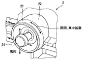
また、従来、吹き出し口に配置されたルーバの向きにより、一つの吹き出し口から吹き出される風の向きを調整する技術が広く知られている。特許文献2に開示の風向き調整装置は、吹き出し口のルーバに機械的に連結された操作子を左右に移動させることで、ルーバの左右の向きを変更する。また、この操作子とは別にルーバに機械的に連結された操作ノブを左右に移動させると、ルーバの向きが、風の流れの上流側に対して下流側が狭まり、あるいは、その反対に、上流側に対して下流側が広がる。これにより、風の集中拡散度合いが変化する。さらに、操作ノブおよび操作子とは別体のシャッタ操作ノブもルーバに機械的に連結されており、このシャッタ操作ノブを上下に回動操作することによって、吹き出し口の開閉を行う。
Conventionally, a technique for adjusting the direction of wind blown from one blowout port according to the direction of a louver arranged at the blowout port is widely known. The wind direction adjusting device disclosed in
また、特許文献3−6に開示されているように、吹き出し口よりも、風の流路の上流側で、その吹き出し口から吹き出される風の上下左右の向きの調整、風の集中拡散度合いの調整、風の流路の開閉を電子制御により行う技術も広く知られている。 Further, as disclosed in Patent Documents 3-6, on the upstream side of the air flow path from the air outlet, adjustment of the vertical and horizontal directions of the wind blown from the air outlet, the degree of concentrated concentration of the wind A technique for adjusting the air flow and opening / closing the air flow path by electronic control is also widely known.
1つの吹き出し口から吹き出される風の向きを、吹出し口から離れた操作部により設定できる車両用空調装置が考えられる。1つの吹き出し口から吹き出される風の向きを、吹き出し口から離れた操作部で調整できる場合、特許文献1のように、どの吹き出し口から風が吹き出されているかが表示されるだけでは、吹き出し口から吹き出されている風の向きを把握することは困難である。
A vehicle air conditioner is conceivable in which the direction of the wind blown out from one blowout port can be set by an operation unit away from the blowout port. When the direction of the wind blown from one blowout port can be adjusted by the operation unit away from the blowout port, as shown in
特に、風向きを調整する機構が吹き出し口よりも風の流路の上流側に位置している場合、吹き出し口を見ることによっても、その吹き出し口から吹き出される風の向きを把握することが困難である。 In particular, when the mechanism for adjusting the wind direction is located on the upstream side of the air flow path from the air outlet, it is difficult to grasp the direction of the air blown from the air outlet even by looking at the air outlet. It is.
本発明は、この事情に基づいて成されたものであり、その目的とするところは、車両用空調装置とともに用いられ、吹き出し口から吹き出される風の向きを容易に把握することができる車両空調用表示装置を提供することにある。 The present invention has been made based on this situation, and the object of the present invention is to be used together with a vehicle air conditioner and to easily grasp the direction of the wind blown from the outlet. It is to provide a display device.
上記目的は独立請求項に記載の特徴の組み合わせにより達成され、また、下位請求項は、発明の更なる有利な具体例を規定する。特許請求の範囲に記載した括弧内の符号は、一つの態様として後述する実施形態に記載の具体的手段との対応関係を示すものであって、本発明の技術的範囲を限定するものではない。 The above object is achieved by a combination of the features described in the independent claims, and the subclaims define further advantageous embodiments of the invention. Reference numerals in parentheses described in the claims indicate a correspondence relationship with specific means described in the embodiments described later as one aspect, and do not limit the technical scope of the present invention. .
上記目的を達成するための第1発明は、1つの吹き出し口(4)から吹き出される風の向きを、吹き出し口から離れた操作部(2)により調整でき、かつ、吹き出し口から吹き出される風の向きを調整する機構(14、15、16、17)が吹き出し口よりも風の流路の上流側に位置しており、吹き出し口から吹き出される風の集中拡散度合いを調整する機能を備えている車両用空調装置(1)とともに用いられ、車両の車室において運転席から視認可能な位置に設置された表示部(52)と、表示部に、吹き出し口から吹き出される風の向きを表示する表示制御部(51)とを備え、表示制御部は、表示部に、車両の車室を三次元的に表す車室画像(7)を表示するとともに、車両用空調装置が空調を行っている領域に対応する車室画像内の位置に、車両用空調装置が行っている空調の状態を示す空調画像(8、9)を重畳表示するものであって、車室画像に、空調画像として、吹き出し口またはその付近から風の吹き出される向きに延びる風情報画像を重畳表示し、風情報画像は、集中拡散度合いに応じて幅が変化することを特徴とする車両空調用表示装置であって、車両用空調装置は、吹き出し口から吹き出される風の向きを、車両の前席乗員の顔およびその周辺を含むエリアである顔周辺エリアの一部を選択したエリアに向かう向きとすることができ、車室画像は、車室を、車室の斜め後方の上方より見た三次元画像であり、表示制御部は、車室画像に加えて、車両の正面から見た前席乗員の顔を表す画像を含んでいる顔周辺エリア画像(10、210)に、顔周辺エリアにおいて吹き出し口から吹き出される風が向かう方向を表す風向き図形(103)を重畳した画像を、表示部に表示することを特徴とする車両空調用表示装置である。
第2発明は、1つの吹き出し口(4)から吹き出される風の向きを、吹き出し口から離れた操作部(2)により調整でき、かつ、吹き出し口から吹き出される風の向きを調整する機構(114、115、116、117)が吹き出し口よりも風の流路の上流側に位置しており、吹き出し口から吹き出される風の向きを、車両の前席乗員の顔およびその周辺を含むエリアである顔周辺エリアの一部を選択したエリアに向かう向きとすることができる車両用空調装置(1)とともに用いられ、車両の車室において運転席から視認可能な位置に設置された表示部(52)と、表示部に、吹き出し口から吹き出される風の向きを表示する表示制御部(51)とを備え、表示制御部は、車両の正面から見た前席乗員の顔を表す画像を含んでいる顔周辺エリア画像(10、210)に、顔周辺エリアにおいて吹き出し口から吹き出される風が向かう方向を表す風向き図形(103)を重畳した画像を、表示部に表示することを特徴とする車両空調用表示装置である。
In the first invention for achieving the above object, the direction of the wind blown out from one blowout port (4) can be adjusted by the operation unit (2) away from the blowout port, and blown out from the blowout port. The mechanism (14, 15, 16, 17) for adjusting the direction of the wind is positioned upstream of the air flow path from the air outlet, and has a function of adjusting the degree of concentrated diffusion of the air blown from the air outlet. The display unit (52) used in the vehicle air conditioner (1) and installed at a position visible from the driver's seat in the vehicle cabin, and the direction of the wind blown from the outlet to the display unit The display control unit (51) displays a vehicle cabin image (7) that three-dimensionally represents the vehicle cabin on the display unit, and the vehicle air conditioner performs air conditioning. In the cabin image corresponding to the area you are going to An air-conditioning image (8, 9) indicating the state of air-conditioning performed by the vehicle air-conditioning apparatus is superimposed on the position, and air is blown out from the outlet or the vicinity thereof as an air-conditioning image on the cabin image. superimposed display wind information image extending in a direction that is, wind information image is a display device for vehicle air conditioning, wherein the width of which changes in accordance with concentration degree of diffusion, air conditioning system, outlet The direction of the wind blown out from the vehicle can be set to a direction toward a selected area of the face peripheral area, which is an area including the face of the front seat occupant of the vehicle and the periphery thereof. Is a three-dimensional image viewed from above obliquely behind the passenger compartment, and the display control unit includes a peripheral image including an image representing the face of the front seat occupant viewed from the front of the vehicle in addition to the passenger compartment image. Area around the face (10, 210) An image obtained by superimposing the wind direction figure (103) that represents the direction in which air blown out from the left and outlet is directed, is a display device for vehicle air conditioning, characterized in that the display unit.
The second aspect of the invention is a mechanism that can adjust the direction of the wind blown from one blowout port (4) by the operation unit (2) away from the blowout port and adjust the direction of the wind blown from the blowout port. (114, 115, 116, 117) are positioned upstream of the air flow path from the air outlet, and the direction of the air blown out from the air outlet includes the face of the front seat occupant of the vehicle and its surroundings. A display unit that is used together with the vehicle air conditioner (1) that can be directed to a selected area of a face peripheral area that is an area, and that is installed at a position that is visible from the driver's seat in the vehicle cabin (52) and a display control unit (51) for displaying the direction of the wind blown from the air outlet on the display unit, and the display control unit is an image representing the front seat occupant's face as viewed from the front of the vehicle Including face around A vehicle air-conditioning display characterized in that an image (10, 210) is superimposed on a wind direction figure (103) representing a direction in which a wind blown from a blowout port is directed in a face peripheral area on a display unit. Device.
本発明によれば、運転席から視認可能な位置に設置された表示部に、吹き出し口から吹き出される風の向きが表示される。したがって、操作部を操作する者は、この表示部を見ることで、吹き出し口から吹き出される風の向きを容易に把握することができる。 According to the present invention, the direction of the wind blown out from the air outlet is displayed on the display unit installed at a position visible from the driver's seat. Therefore, the person who operates the operation unit can easily grasp the direction of the wind blown out from the air outlet by looking at the display unit.
以下、本発明の実施形態について図面を用いて説明する。 Hereinafter, embodiments of the present invention will be described with reference to the drawings.
(車両用空調システム100の構成)
図1に示す車両用空調システム100は、車両に搭載される。この車両用空調システム100は、車両用空調装置(以下、空調装置)1、操作デバイス2、操作スイッチ3、表示装置5、顔位置認識装置6を含んでいる。以降では、車両用空調システム100を搭載した車両を自車と呼ぶ。
(Configuration of vehicle air conditioning system 100)
A vehicle
空調装置1は、複数の空調部を備える。具体的には、空調装置1は、空調部として、主空調部11、輻射ヒータ12、シート空調部13、加湿部14を備える。
The
輻射ヒータ12は、ダッシュボードの下部や、前席シートの下部などの所定位置に、1つまたは複数備えられている。
One or a plurality of
シート空調部13は、シート内部に配置されており、シートを介して、そのシートに着座した乗員に対する空調を行う。シート空調部13の方式は、公知の種々の方式を用いることができる。たとえば、シート空調部13は、シート内部に吸い込み口を備え、その吸い込み口から車室の空気を吸い込む方式や、シート内部にダクトを備え、そのダクト内に冷房空気や暖房空気を流す方式などを用いることができる。加湿部14は、車室を加湿する。
The seat air-
主空調部11は、自車の車室に複数設けられた吹き出し口4(図2参照)から吹き出す風に関する調整(つまり、空調)を行う装置である。また、車室に、1つまたは複数の空気吸い込み口を備え、車室の空気をその吸い込み口から吸い込む構成を備えていてもよい。
The main air-
主空調部11が行う吹き出し口4を用いた空調としては、吹き出し口4の開閉、吹き出す風の集中拡散度合いの調整、吹き出す風の向き(以下、風向)の調整、吹き出す風の温度の調整、吹き出す風の量(以下、風量)の調整、風を吹き出す吹き出し口4の選択などがある。また、吸い込み口に関する空調としては、吸い込み口から吸い込む空気の流量の調整がある。なお、吹き出し口4と吸い込み口とを総称して空調口ということもできる。
The air conditioning using the air outlet 4 performed by the main
図2には、3つの吹き出し口4a、4b、4cが示されている。これらの吹き出し口4a、4b、4cを特に区別しないときは、単に吹き出し口4とする。また、吹き出し口4は、3つの吹き出し口4a、4b、4c以外にも、インストゥルパネル下部や、前席背面、前席下などにも設けられている。
FIG. 2 shows three
吹き出し口4aは、フロントウィンドシールドの付近であって、運転席前方に設けられている。吹き出し口4bは、フロントウィンドシールドの付近であって、助手席前方に設けられている。したがって、これらの吹き出し口4a、4bは、運転席に着座した運転者の手が届かない位置にある。これらの吹き出し口4a、4bの形状は、車幅方向に延びる長手直線状である。一方、吹き出し口4cは、メータフードの隙間に形成されている。
The
説明を図1に戻す。操作デバイス2a、2bは、吹き出し口4の開閉、吹き出し口4から吹き出す風の集中拡散度合いの調整、吹き出し口4から吹き出す風の風向の調整を行うための操作デバイスである。2つの操作デバイス2a、2bを区別しない場合には、単に操作デバイス2とする。この操作デバイス2は操作部に相当する。
Returning to FIG. The
操作デバイス2a、2bが設けられている位置は、図2に示すように、自車のダッシュボードの幅方向中央付近であり、ダッシュボードから車室後方に向けて突き出して設けられる。
As shown in FIG. 2, the position where the
2つの操作デバイス2a、2bのうち、右側の操作デバイス2aが運転席用、左側の操作デバイス2bが助手席用である。これらの操作デバイス2a、2bは、運転席に着座した運転者が操作できる位置にあり、また、助手席用の操作デバイス2bは、助手席に着座した乗員も操作できる位置にある。
Of the two
運転席用の操作デバイス2aは、運転席用の吹き出し口4aの開閉等を行うためのものであり、助手席用の操作デバイス2bは、助手席用の吹き出し口4bの開閉等を行うためのものである。
The driver's
操作スイッチ3は、操作デバイス2により設定できる種類以外の空調に関する調整を行うためのスイッチである。たとえば、操作スイッチ3は、吹き出し口4の選択、空調温度の設定、風量の設定、輻射ヒータ12の操作、シート空調部13の操作などを行うためのスイッチである。なお、シート空調部13の操作を行うための操作スイッチ3を、各シート付近に設けてもよい。
The
車両空調用表示装置である表示装置5は、ディスプレイECU51と、表示部52を備えている。表示部52は、カラー表示が可能なものであり、液晶ディスプレイ等を用いて構成することができる。ディスプレイECU51は、表示制御部に相当しており、表示部52に、空調装置1で設定されている風向などの空調の状態を表示させる。
A
表示部52は、自車を運転中の運転者から見やすい位置に設けられる。具体的には、本実施形態では、図2に示すように、自車のダッシュボード上に、そのダッシュボードの車幅方向中央付近に設けられる。したがって、操作デバイス2、操作スイッチ3よりも、車両前方に設置されていることになる。
The
この表示装置5は、車両用空調システム100とは別の車載システム、たとえば、オーディオシステムなどと兼用で用いられてもよい。なお、表示部52として、HUD(Head-Up Dispray)を用いる構成としてもよい。
The
顔位置認識装置6は、前席乗員の顔およびその付近を撮影するカメラと、そのカメラが撮影した画像を解析して、前席乗員の顔位置を決定する制御部とを備えた公知の構成である。顔位置認識装置6は、決定した前席乗員(すなわち運転者と助手席の乗員)の顔位置を表す信号をディスプレイECU51に逐次出力する。
The face
(操作デバイス2の説明)
操作デバイス2は、図3に示すように、ダッシュボードに固定された円筒状の基部22を有している。基部22は、おおよそ円筒状の形状をしている。基部22は、軸心が自車の前後方向に平行となるように設けられている。
(Description of operation device 2)
As shown in FIG. 3, the
円筒型操作部21も円筒状であり、基部22に対して、右回りおよび左回りの両方向に相対回転可能に基部22と嵌合している。円筒型操作部21は、この円筒型操作部21を備える操作デバイス2に対応する吹き出し口4の開閉、吹き出し口4から吹き出す風の集中拡散度合いの調整を行うために乗員が操作する操作部である。
The
円筒型操作部21の基部22に対する相対回転位置は、本実施形態では、「閉」、「集中」、「通常」、「拡散」の4つの位置が可能である。「閉」は、操作デバイス2に対応する吹き出し口4から風が出ないようにする場合の位置である。「集中」は、操作デバイス2に対応する吹き出し口4から狭い幅に集中した風が出るようにする場合の位置である。「拡散」は、操作デバイス2に対応する吹き出し口4から、広い幅に広がる風が出るようにする場合の位置である。「通常」は、操作デバイス2に対応する吹き出し口4から、「集中」よりも拡散するが、「拡散」よりも集中した風を吹き出す場合の位置である。
In this embodiment, four positions of “closed”, “concentration”, “normal”, and “diffusion” are possible as relative rotation positions of the
これら4つの位置は、円筒型操作部21が基部22に対して一方向に相対回転されることで、「閉」、「集中」、「通常」、「拡散」の順に変化し、反対方向に円筒型操作部21が操作されることで、「拡散」、「通常」、「集中」、「閉」の順に変化する。
These four positions change in the order of “closed”, “concentration”, “normal”, and “diffusion” by rotating the
操作デバイス2は、円筒型操作部21が上記「閉」、「集中」、「通常」、「拡散」のいずれかの位置である場合に、その位置を表す信号をエアコンECU111に出力する。
The
また、操作デバイス2は、風向の調整を行うためのスティック型操作部24を備えている。スティック型操作部24は、その軸心が円筒型操作部21の軸心と一致する位置が可能であり、この位置から、スティック型操作部24は、先端が円筒型操作部21の軸心から上下左右に離れる方向に傾けることができるようになっている。操作デバイス2は、円筒型操作部21の位置を表す信号をエアコンECU111に出力することに加えて、スティック型操作部24が傾いている方向を表す信号もエアコンECU111に出力する。
Further, the
(主空調部11の説明)
続いて、図1を用いて、主空調部11の構成を説明する。主空調部11は、図1に示すように、エアコンECU111、閉塞板112、開閉用モータ113、横ルーバ114、横ルーバ用モータ115、縦ルーバ116、縦ルーバ用モータ117、ブロア118、温度調整部119を備えている。
(Description of the main air conditioning unit 11)
Then, the structure of the main air-
閉塞板112は、吹き出し口4よりも風の流路の上流側でその風邪の流路を塞ぐための可動式の閉塞板であり、一部または全部の吹き出し口4に対して設けられる。開閉用モータ113は、各閉塞板112を、別々に駆動するモータである。
The
横ルーバ114は、吹き出し口4a、4bよりも風の流路の上流側であって、吹き出し口4a、4bの付近に設けられている。なお、横ルーバ114は、運転席に着座した運転者からは視認できない位置に設けられている。
The
横ルーバ114は、吹き出し口4a、4bの長手方向(つまり、自車の車幅方向)に延びるように形成されている複数の長板を備える。これら複数の長板は、吹き出し口4a、4bの短手方向に互いに間隔をおいて配列されている。横ルーバ114の各長板は、それぞれ吹き出し口4a、4bの長手方向に延びたシャフトを中心に回動可能に配置されている。
The
横ルーバ用モータ115は、横ルーバ114の各長板のシャフト駆動用のモータであって、各長板のシャフトを個別に駆動できるように例えば複数個のモータからなる。
The
縦ルーバ116も、吹き出し口4a、4bよりも風の流路の上流側であって、吹き出し口4a、4bの付近に設けられている。この縦ルーバ116も、運転席に着座した運転者からは視認できない位置に設けられている。
The
縦ルーバ116は、吹き出し口4a、4bの短手方向に延びるように形成されている複数の長板を備える。これら複数の長板は、吹き出し口4a、4bの長手方向に互いに間隔をおいて配列されている。縦ルーバ116の各長板は、それぞれ吹き出し口4a、4bの短手方向に延びたシャフトを中心に回動可能に配置されている。
The
縦ルーバ用モータ117は、縦ルーバ116の各長板のシャフト駆動用のモータであって、各長板のシャフトを個別に駆動できるように例えば複数個のモータからなる。
The vertical louver motor 117 is a motor for driving the shaft of each long plate of the
横ルーバ114の向きが横ルーバ用モータ115により制御されることで、その横ルーバ114の下流にある吹き出し口4から吹き出される風の上下方向の向きが調整される。また、縦ルーバ116の向きが縦ルーバ用モータ117により制御されることで、その縦ルーバ116の下流にある吹き出し口4から吹き出される風の左右方向の向きが調整される。本実施形態では、これら横ルーバ114、縦ルーバ116、横ルーバ用モータ115、縦ルーバ用モータ117が、吹き出し口4から吹き出される風の向きを調整する機構である。
By controlling the direction of the
ブロア118は、吹き出し口4から吹き出される風の風量を調整する。温度調整部119は、熱交換器を備えており、吹き出し口4から吹き出す風の温度を調整する。これらブロア118、温度調整部119を備えていることから、主空調部11は、吹き出し口4から吹き出される風の風量を調整する機能、吹き出し口4から吹き出される風の温度を調整する機能を備える。
The blower 118 adjusts the air volume of the air blown from the air outlet 4. The
エアコンECU111は、CPU、ROMやRAM等のメモリなどを備え、操作デバイス2、操作スイッチ3から入力される信号をもとに、ROMに記憶された制御プログラムを実行することで、自車の空調に関する処理を実行する。
The
例えば、エアコンECU111は、操作スイッチ3から入力される信号をもとに、開閉用モータ113を制御することで、風を吹き出す吹き出し口4を切り替える。また、操作スイッチ3から入力される信号をもとに、ブロア118、温度調整部119を調整して、風量、風の温度を制御する。また、エアコンECU111は、操作スイッチ3から入力される信号をもとに、輻射ヒータ12、シート空調部13、加湿部14の制御を行う。
For example, the
また、エアコンECU111は、操作デバイス2から入力される信号をもとに、吹き出し口4a、4bの開閉、および吹き出し口4a、4bから吹き出される風の集中拡散度合いを調整する。本実施形態では、吹き出し口4の開閉、および風の集中拡散度合いの調整は、前述した「閉」、「集中」、「通常」、「拡散」の4段階である。
Further, the
円筒型操作部21の位置が「閉」であれば、操作デバイス2に対応する吹き出し口4の上流側に設けられたに対する閉塞板112が流路を閉じるように、その閉塞板112を移動させる開閉用モータ113を駆動させる。
If the position of the
円筒型操作部21の位置が「集中」、「通常」、「拡散」の場合には、操作デバイス2に対応する吹き出し口4の上流側に設けられた閉塞板112が流路を開く位置となるように、その閉塞板112を移動させる開閉用モータ113を駆動させる。
When the position of the
さらに、円筒型操作部21の位置が「集中」の場合、エアコンECU111は、この円筒型操作部21を備える操作デバイス2に対応する吹き出し口4の上流側に設けられた縦ルーバ116を回転させるために縦ルーバ用モータ117を制御する。縦ルーバ用モータ117による縦ルーバ116の制御は、具体的には、縦ルーバ116の隣接する長板同士の間隔が、吹き出し方向に向かうほど狭くなるように各長板を回動させる。これにより、吹き出す風の左右方向の幅が狭くなる。
Further, when the position of the
加えて、円筒型操作部21の位置が「集中」の場合、エアコンECU111は、横ルーバ用モータ115を制御して、横ルーバ114の隣接する長板同士の間隔が、吹き出し方向に向かうほど狭くなるように各長板を回動させてもよい。この場合、吹き出し口4から吹き出す風の上下方向の幅も狭くなる。なお、縦ルーバ用モータ117を制御せずに、横ルーバ用モータ115を制御することで、吹き出す風が上下方向に集中するように調整してもよい。
In addition, when the position of the
円筒型操作部21の位置が「通常」の場合、エアコンECU111は、「集中」の場合と同じ縦ルーバ用モータ117を制御して、縦ルーバ116の隣接する長板同士が平行に並ぶように各長板を回動させる。これにより、吹き出す風が集中も拡散もし過ぎないように調整される。加えて、エアコンECU111は、横ルーバ用モータ115を制御して、横ルーバ114の隣接する長板同士が平行に並ぶように各長板を回動させてもよい。
When the position of the
円筒型操作部21の位置が「拡散」の場合、エアコンECU111は、「集中」の場合と同じ縦ルーバ用モータ117を制御して、縦ルーバ116の隣接する長板同士の間隔が、吹き出し方向に向かうほど広くなるように各長板を回動させる。これにより、縦ルーバ116の下流にある吹き出し口4から吹き出す風が拡散する。加えて、エアコンECU111は、横ルーバ用モータ115を制御して、横ルーバ114の隣接する長板同士の間隔が、吹き出し方向に向かうほど広くなるように各長板を回動させてもよい。この場合、吹き出す風の上下方向の幅が拡散する。なお、縦ルーバ用モータ117を制御せずに、横ルーバ用モータ115を制御することで、吹き出す風が上下方向に拡散するように調整してもよい。
When the position of the
また、エアコンECU111は、スティック型操作部24の傾きを表す信号に応じて、このスティック型操作部24を備える操作デバイス2に対応する吹き出し口4から吹き出される風向きを調整する。
Further, the
例えば、スティック型操作部24の傾き方向が自車の上方向や下方向であれば、横ルーバ用モータ115を制御して、横ルーバ114の各長板間の吹き出し口4側の間隔を維持したまま、横ルーバ114の各長板を回動させる。これにより、風の集中拡散度合いが保持されたまま、風向が自車の上方向や下方向に調整される。
For example, if the tilt direction of the stick
また、スティック型操作部24の傾き方向が自車の右方向や左方向であれば、縦ルーバ用モータ117を制御して、縦ルーバ116の各長板間の吹き出し口4側の間隔を維持したまま、縦ルーバ116の各長板を回動させる。これにより、風の集中拡散度合いが保持されたまま、風向が自車の右方向や左方向に調整される。風向の調整は、上下左右の4方向に限らず、横ルーバ用モータ115と縦ルーバ用モータ117との両方を制御することで、4方向よりも細分化して行う構成としてもよい。
Further, if the tilt direction of the stick
なお、エアコンECU111が実行する機能の一部または全部を、一つあるいは複数のIC等によりハードウェア的に構成してもよい。
Note that some or all of the functions executed by the
(表示部52に表示される表示例)
図4は、ディスプレイECU51が表示部52に表示させる画像である。この画像には、車室画像7が含まれている。車室画像7は、この車両用空調システム100が搭載される車種の車室とは異なる画像であってもよいし、この車両用空調システム100が搭載される車種の車室を表している画像であってもよい。
(Display example displayed on the display unit 52)
FIG. 4 is an image displayed on the
この車室画像7は、横長の矩形形状であり車両の車室を三次元的に表している。より詳しくは、車室画像7は、車室を、車室の斜め後方の上方より見た三次元画像である。したがって、車室画像7には、吹き出し口4a、4bが示されている。この車室画像7に、空調装置1が行なっている空調の状態を示す複数の風情報画像8、空調画像9が重畳表示されている。なお、風情報画像8も、請求項の空調画像に相当する。
This vehicle compartment image 7 has a horizontally long rectangular shape and three-dimensionally represents the vehicle compartment. More specifically, the passenger compartment image 7 is a three-dimensional image of the passenger compartment as viewed from above obliquely behind the passenger compartment. Therefore, the passenger compartment image 7 shows the
風情報画像8は、複数の吹き出し口4から吹き出される風に関する情報を表す画像である。図4において、車室画像7に重畳表示されている風情報画像8は、具体的には、風情報画像8a〜8dである。風情報画像8aは、吹き出し口4aの付近から延びており、吹き出し口4aから吹き出される風に関する情報を表している。風情報画像8bは、吹き出し口4bの付近から延びており、吹き出し口4bから吹き出される風に関する情報を表している。風情報画像8cは、運転席背面から後席に向けて吹き出す風に関する情報を表している。風情報画像8dは、助手席背面から後席に向けて吹き出す風に関する情報を表している。
The
また、図4において、車室画像7に重畳表示されている空調画像9は、具体的には、運転席に対してシート空調部13により空調をしていることを示す空調画像9a、助手席に対してシート空調部13により空調をしていることを示す空調画像9b、右後席に対してシート空調部13により空調をしていることを示す空調画像9c、左後席に対してシート空調部13により空調をしていることを示す空調画像9dである。
In FIG. 4, the air-conditioning image 9 superimposed on the passenger compartment image 7 specifically includes an air-
風情報画像8、空調画像9は、全て、それら風情報画像8、空調画像9に対応する領域の空調温度を表す色で表示される。なお、ここでの温度は、空調をしていない場合の室温に対する相対温度である。たとえば、室温よりも低い温度、すなわち、冷房である場合には、風情報画像8、空調画像9は水色とする。なお、冷房である場合に、常に同じ水色である必要はなく、室温との温度差に応じた濃さの色となっていてもよい。
The
風情報画像8は、各風情報画像8に対応する吹き出し口4またはその付近から、風の吹き出される向きに延びる長手形状である。
The
図5には、車室画像7に、図4とは一部別の風情報画像8b、8e、8f、空調画像9a、9b、9e、9f、9g、9h、9iが表示されている例である。図4は冷房時の表示例であり、この図5は暖房時の表示例である。
FIG. 5 shows an example in which the passenger compartment image 7 displays
図5において、風情報画像8eは、運転席前方であってダッシュボードの下部から斜め下方に向けて吹き出される風に関する情報を表している。風情報画像8fは、助手席前方であってダッシュボードの下部から斜め下方に向けて吹き出される風に関する情報を表している。
In FIG. 5, a
空調画像9eは、運転席前方であってダッシュボードの下部に配置された輻射ヒータ12により空調が行われていることを示す画像である。空調画像9fは、助手席前方であってダッシュボードの下部に配置された輻射ヒータ12により空調が行われていることを示す画像である。空調画像9gは、運転席下部に配置された輻射ヒータ12により空調が行われていることを示す画像である。空調画像9hは、助手席下部に配置された輻射ヒータ12により空調が行われていることを示す画像である。空調画像9iは、加湿部14が作動していることを表す画像である。
The air-
図5においても、風情報画像8、空調画像9は、それら風情報画像8、空調画像9に対応する領域の空調温度を表す色で表示される。図5は、前述したように暖房時の表示例であり、暖房である場合には、風情報画像8、空調画像9の色は、たとえばオレンジ色とする。
Also in FIG. 5, the
なお、冷房の場合と同様、暖房の場合の風情報画像8、空調画像9の色も、常に同じオレンジ色である必要はなく、室温との温度差に応じた濃さの色となっていてもよい。
As in the case of cooling, the colors of the
また、風情報画像8e、8fも、各風情報画像8e、8fに対応する吹き出し口4またはその付近から、風の吹き出される向きに延びる画像である。
The
さらに、吹き出し口4a、4bから吹き出される風は、風向および集中拡散度合いが調整できるので、この吹き出し口4a、4bから吹き出される風に関する情報を表す風情報画像8a、8bは、風向に応じて向きが変化し、集中拡散度合いに応じて幅が変化する。また、いずれの風情報画像8も、風量が大きいほど長くなる。すなわち、風量に応じて長さが変化する。
Further, since the wind blown from the
図4、図5の表示例には、車室画像7の下に、助手席設定温度71、風が吹き出されている吹き出し口4がどれであるかを示す図形である作動中吹き出し口図形72、設定風量図形73、運転席設定温度74も表示されている。
In the display examples of FIGS. 4 and 5, an operating air outlet graphic 72, which is a figure indicating the front passenger seat set
また、表示部52には、車室画像7の左右の下部の、部分的にその車室画像7に重畳する位置に、顔周辺エリア画像10a、10bも表示されている。
In addition, on the
右側の顔周辺エリア画像10aは、車両の正面から見た運転者の顔を表す運転者画像101と運転者の周辺を含んだ画像である。本実施形態の運転者画像101は、実際の運転者を撮影した画像ではなく、予め用意された画像である。ただし、実際の運転者を撮影した画像を運転者画像101としてもよい。
The right face
顔周辺エリア画像10aは、予め固定されたエリアである。一方、ディスプレイECU51は、顔位置認識装置6から運転者の顔位置を表す信号を取得し、顔周辺エリア画像10a内において、その信号が表す運転者の顔の位置に対応した位置に運転者画像101を表示する。よって、運転者画像101の位置は、顔位置認識装置6が検出した運転者の顔位置に応じて移動する。
The face
左側の顔周辺エリア画像10bは、車両の正面から見た助手席の乗員の顔を表す助手席乗員画像102と助手席の乗員の周辺を含んだ画像である。この助手席乗員画像102も、実際の助手席の乗員を撮影した画像ではなく、予め用意された画像である。ただし、実際の助手席の乗員を撮影した画像を助手席乗員画像102としてもよい。
The left face
顔周辺エリア画像10bも、予め固定されたエリアである。一方、助手席乗員画像102は、運転者画像101と同様、顔位置認識装置6が検出した助手席の乗員の顔位置に応じて移動する。
The face
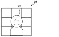
また、図4に示す顔周辺エリア画像10a、10b、図5に示す顔周辺エリア画像10bには、風向き図形103が重畳表示されている。この風向き図形103は、互いに平行な2本の縦線103aと、互いに平行な2本の横線103bとにより囲まれる矩形範囲により、吹き出し口4a、4bから吹き出される風が向かう向きを表している画像である。
Further, the wind direction graphic 103 is superimposed and displayed on the face
右側の顔周辺エリア画像10aに重畳表示されている風向き図形103は、矩形範囲が、運転者画像101における頭の位置のすぐ上に位置している。また、この矩形範囲は左右方向の長さ、および、上下方向の長さともに、大きさの目安として一定間隔で示されている格子状の目盛線104の3本分である。
In the wind direction graphic 103 superimposed on the right face
この風向き図形103から、吹き出し口4aから吹き出される風が、運転者のすぐ上の狭い範囲を通過することが分かる。
From this wind direction figure 103, it can be seen that the wind blown from the
これに対して、図4、図5において、左側の顔周辺エリア画像10bに重畳表示されている風向き図形103は、矩形範囲が、助手席乗員画像102における顔の位置を通っている。また、この矩形範囲の左右方向の長さは、目盛線104の5本分である。この風向き図形103から、吹き出し口4bから吹き出される風が、助手席の乗員の顔付近に、横方向に比較的広い幅で向かうことが分かる。
On the other hand, in FIG. 4 and FIG. 5, the wind direction graphic 103 superimposed on the left face
(実施形態のまとめ)
以上、説明した本実施形態では、運転席から視認可能な位置に設置された表示部52に、吹き出し口4から吹き出される風の向きが表示される。したがって、操作デバイス2を操作する者は、この表示部52を見ることで、吹き出し口4から吹き出される風の向きを容易に把握することができる。
(Summary of embodiment)
As described above, in the present embodiment described above, the direction of the wind blown out from the outlet 4 is displayed on the
特に、本実施形態では、表示部52に、三次元的に車両の車室を表す車室画像7が表示され、この車室画像7に、吹き出し口4またはその付近から風の吹き出される向きに延びる風情報画像8a〜8fが重畳表示される。したがって、風情報画像8a〜8fが車室画像7に重畳表示された表示部52を運転者が見ることにより、運転者は、複数の風情報画像8a〜8fに対応する吹き出し口4から吹き出されている風の向きを、一度に把握することができる。
In particular, in the present embodiment, a vehicle compartment image 7 that three-dimensionally represents a vehicle compartment is displayed on the
また、三次元的に車両の車室を表す車室画像7に風情報画像8を重畳表示することで、風向きだけでなく、吹き出し口4から吹き出される風に関する種々の情報を、表示部52を見た運転者は一度に把握することができる。
In addition, by displaying the
具体的には、風情報画像8は、風量に応じて長さが変化することから、運転者は、複数の吹き出し口4から吹き出されている風の風量も、一度に把握することができる。また、集中拡散度合いを調整できる吹き出し口4a、4bに対応する風情報画像8a、8bは、風の集中拡散度合いに応じて幅が変化することから、運転者は、複数の吹き出し口4から吹き出されている風の集中拡散度合いも、一度に把握することができる。また、風情報画像8は、風の温度に応じて色が変化することから、運転者は、複数の吹き出し口4から吹き出されている風の温度も、一度に把握することができる。
Specifically, since the length of the
さらに、車室画像7には、輻射ヒータ12、シート空調部13、加湿部14により空調が行われていることを表している空調画像9も表示される。したがって、車室画像7を見ることで、運転者は、輻射ヒータ12、シート空調部13、加湿部14が作動しているかどうかも、一度に把握することができる。
Further, in the passenger compartment image 7, an air-conditioning image 9 indicating that air-conditioning is being performed by the
また、本実施形態では、操作デバイス2、操作スイッチ3は、運転席に着座した運転者の手が届く位置に配置されている一方、表示部52は操作デバイス2、操作スイッチ3よりも、車両前方に設置されている。したがって、運転中に空調の状態を確認あるいは空調の状態を変更する場合に、視線移動を少なくすることができる。
Further, in the present embodiment, the
また、本実施形態では、風情報画像8により、吹き出し口4から吹き出される風の状態を表示することに加え、顔周辺エリア画像10に風向き図形103を重畳表示することでも、吹き出し口4a、4bから吹き出される風の向き、風の温度を表示する。
Further, in the present embodiment, in addition to displaying the state of the wind blown out from the blowout port 4 by the
車室画像7に風情報画像8を重畳表示することで、複数の吹き出し口4から吹き出される風に関する情報を一度に表すことができる。しかし、車室画像7に風情報画像8を重畳表示しても、前席乗員に対してどの位置に風が向かっているかは分かりにくい。そこで、顔周辺エリア画像10に風向き図形103を重畳表示する。これにより、前席乗員に対してどの位置に風が向かっているかも容易に把握することができる。
By superimposing and displaying the
以上、本発明の実施形態を説明したが、本発明は上述の実施形態に限定されるものではなく、次の変形例も本発明の技術的範囲に含まれ、さらに、下記以外にも要旨を逸脱しない範囲内で種々変更して実施できる。 As mentioned above, although embodiment of this invention was described, this invention is not limited to the above-mentioned embodiment, The following modification is also contained in the technical scope of this invention, Furthermore, the summary other than the following is also included. Various modifications can be made without departing from the scope.
<変形例1>
たとえば、前述の実施形態では、運転者は、操作デバイス2と操作スイッチ3により、空調装置1を操作するが、これらに代えて、タッチパネルを用いて空調装置1を操作してもよい。
<
For example, in the above-described embodiment, the driver operates the
<変形例2>
前述の実施形態では、吹き出し口4a、4bから吹き出される風の向き、および、風の集中拡散度合いを調整できるようになっていたが、その他の吹き出し口4から吹き出される風の向き、および集中拡散度合いも調整できるようになっていてもよい。なお、コアンダ効果を利用して風向きの調整を行なってもよい。
<
In the above-described embodiment, the direction of the wind blown from the
<変形例3>
前述の実施形態では、閉塞板112を用いて吹き出し口4から吹き出される風を止めていたが、ブロア18を停止させて吹き出し口4から吹き出される風を止めてもよい。
<
In the above-described embodiment, the air blown from the blowout port 4 is stopped using the
<変形例4>
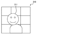
図6、図7は、前述の実施形態の顔周辺エリア画像10とは別の顔周辺エリア画像210を示している。図7の前席乗員画像211は、図6の前席乗員画像211とは顔の位置が異なっている。これら図6、図7から分かるように、前席乗員の顔を表す前席乗員画像211は、顔位置認識装置6が検出した前席乗員の顔位置に応じて移動する。
<Modification 4>
6 and 7 show a face
1:空調装置 2:操作デバイス 3:操作スイッチ 4:吹き出し口 5:表示装置 6:顔位置認識装置 7:車室画像 8:風情報画像 9:空調画像 10:顔周辺エリア画像 11:主空調部 12:輻射ヒータ 13:シート空調部 14:加湿部 18:ブロア 21:円筒型操作部 22:基部 24:スティック型操作部 51:ディスプレイECU 52:表示部 71:助手席設定温度 72:作動中吹き出し口図形 73:設定風量図形 74:運転席設定温度 100:車両用空調システム 101:運転者画像 102:助手席乗員画像 103:風向き図形 104:目盛線 111:エアコンECU 112:閉塞板 113:開閉用モータ 114:横ルーバ 115:横ルーバ用モータ 116:縦ルーバ 117:縦ルーバ用モータ 118:ブロア 119:温度調整部 210:顔周辺エリア画像 211:前席乗員画像 1: Air conditioner 2: Operation device 3: Operation switch 4: Outlet 5: Display device 6: Face position recognition device 7: Cabin image 8: Wind information image 9: Air condition image 10: Face peripheral area image 11: Main air conditioner Unit 12: Radiation heater 13: Seat air conditioning unit 14: Humidification unit 18: Blower 21: Cylindrical operation unit 22: Base 24: Stick type operation unit 51: Display ECU 52: Display unit 71: Passenger seat set temperature 72: In operation Air outlet graphic 73: Set air volume graphic 74: Driver seat set temperature 100: Vehicle air conditioning system 101: Driver image 102: Passenger seat passenger image 103: Wind direction graphic 104: Scale line 111: Air conditioner ECU 112: Blocking plate 113: Opening and closing Motor 114: horizontal louver 115: motor for horizontal louver 116: vertical louver 117: for vertical louver Motor 118: Blower 119: Temperature adjustment unit 210: Face peripheral area image 211: Front seat occupant image
Claims (9)
車両の車室において運転席から視認可能な位置に設置された表示部(52)と、
前記表示部に、前記吹き出し口から吹き出される風の向きを表示する表示制御部(51)とを備え、
前記表示制御部は、前記表示部に、車両の車室を三次元的に表す車室画像(7)を表示するとともに、前記車両用空調装置が空調を行っている領域に対応する前記車室画像内の位置に、前記車両用空調装置が行っている空調の状態を示す空調画像(8、9)を重畳表示するものであって、前記車室画像に、前記空調画像として、前記吹き出し口またはその付近から前記風の吹き出される向きに延びる風情報画像を重畳表示し、前記風情報画像は、前記集中拡散度合いに応じて幅が変化する車両空調用表示装置であって、
前記車両用空調装置は、前記吹き出し口から吹き出される風の向きを、前記車両の前席乗員の顔およびその周辺を含むエリアである顔周辺エリアの一部を選択したエリアに向かう向きとすることができ、
前記車室画像は、前記車室を、前記車室の斜め後方の上方より見た三次元画像であり、
前記表示制御部は、前記車室画像に加えて、前記車両の正面から見た前記前席乗員の顔を表す画像を含んでいる顔周辺エリア画像(10、210)に、前記顔周辺エリアにおいて前記吹き出し口から吹き出される風が向かう方向を表す風向き図形(103)を重畳した画像を、前記表示部に表示することを特徴とする車両空調用表示装置。 A mechanism for adjusting the direction of the wind blown from one blowout port (4) and the direction of the wind blown from the blowout port can be adjusted by the operation unit (2) away from the blowout port (114, 115, 116, 117) are located upstream of the air flow path from the air outlet and have a function of adjusting the degree of concentrated diffusion of the air blown out from the air outlet. Used with (1),
A display unit (52) installed at a position visible from the driver's seat in the vehicle cabin;
The display unit includes a display control unit (51) for displaying the direction of the wind blown from the outlet.
The display control unit displays, on the display unit, a vehicle compartment image (7) that three-dimensionally represents a vehicle compartment of the vehicle, and the vehicle compartment corresponding to a region in which the vehicle air conditioner is air-conditioned. An air-conditioning image (8, 9) indicating the state of air-conditioning performed by the vehicle air-conditioning apparatus is superimposed and displayed at a position in the image, and the air outlet image is displayed on the vehicle cabin image as the air-conditioning image. or superimpose wind information image extending in a direction that is blown out from the vicinity of the wind, the wind information image is a display device for a vehicle both conditioning width you change depending on the concentration degree of diffusion,
In the vehicle air conditioner, the direction of the wind blown from the outlet is directed to an area selected from a part of the face peripheral area, which is an area including the face of the front seat occupant of the vehicle and its periphery. It is possible,
The passenger compartment image is a three-dimensional image of the passenger compartment as viewed from above obliquely behind the passenger compartment.
In addition to the passenger compartment image, the display control unit includes a face peripheral area image (10, 210) including an image representing the face of the front seat occupant viewed from the front of the vehicle in the face peripheral area. A display device for vehicle air conditioning, wherein an image on which a wind direction graphic (103) representing a direction in which a wind blown from the blowout port is directed is superimposed is displayed on the display unit.
前記車両用空調装置は、前記吹き出し口から吹き出される風量を調整する機能を備え、
前記風情報画像は、前記風量に応じて長さが変化することを特徴とする車両空調用表示装置。 In claim 1,
The vehicle air conditioner has a function of adjusting the amount of air blown from the outlet,
The vehicle air-conditioning display device, wherein the wind information image changes in length according to the air volume.
前記車両用空調装置は、吹き出す風の向きが前記操作部により調整される前記吹き出し口を複数備え、
前記表示制御部は、前記車室画像に、複数の前記吹き出し口から吹き出される風に対応する複数の前記風情報画像を重畳表示することを特徴とする車両空調用表示装置。 In claim 1 or 2,
The vehicle air conditioner includes a plurality of the air outlets in which the direction of the blowing air is adjusted by the operation unit,
The said display control part superimposes and displays the said several wind information image corresponding to the wind which blows off from the said several blower outlet on the said vehicle interior image, The display apparatus for vehicles characterized by the above-mentioned.
車両の車室において運転席から視認可能な位置に設置された表示部(52)と、
前記表示部に、前記吹き出し口から吹き出される風の向きを表示する表示制御部(51)とを備え、
前記表示制御部は、前記車両の正面から見た前記前席乗員の顔を表す画像を含んでいる顔周辺エリア画像(10、210)に、前記顔周辺エリアにおいて前記吹き出し口から吹き出される風が向かう方向を表す風向き図形(103)を重畳した画像を、前記表示部に表示することを特徴とする車両空調用表示装置。 A mechanism for adjusting the direction of the wind blown from one blowout port (4) and the direction of the wind blown from the blowout port can be adjusted by the operation unit (2) away from the blowout port (114, 115, 116, 117) are located on the upstream side of the air flow path from the air outlet, and the direction of the air blown out from the air outlet includes the face of the front seat occupant of the vehicle and its surroundings. It is used with the vehicle air conditioner (1) that can be directed to a selected area of a part of the face peripheral area that is an area,
A display unit (52) installed at a position visible from the driver's seat in the vehicle cabin;
The display unit includes a display control unit (51) for displaying the direction of the wind blown from the outlet.
The display control unit applies a wind blown from the outlet in the face peripheral area to the face peripheral area image (10, 210) including an image representing the face of the front seat occupant as viewed from the front of the vehicle. The vehicle air-conditioning display device displays an image on which the wind direction graphic (103) representing the direction of the vehicle is superimposed on the display unit.
前記表示制御部は、前記顔周辺エリア画像に前記風向き図形(103)を重畳した画像を、前記表示部に表示することに加えて、前記表示部に、車両の車室を前記車室の斜め後方の上方より見て三次元的に表す車室画像(7)を表示するとともに、前記車両用空調装置が空調を行っている領域に対応する前記車室画像内の位置に、前記車両用空調装置が行っている空調の状態を示す空調画像(8、9)を重畳表示するものであり、前記空調画像として、前記吹き出し口またはその付近から前記風の吹き出される向きに延びる風情報画像を表示することを特徴とする車両空調用表示装置。 In claim 4 ,
The display control unit displays an image obtained by superimposing the wind direction graphic (103) on the face peripheral area image on the display unit, and displays a vehicle compartment on the display unit. A vehicle compartment image (7) represented three-dimensionally as viewed from above is displayed, and the vehicle air conditioner is positioned at a position in the vehicle compartment image corresponding to a region where the vehicle air conditioner performs air conditioning. An air-conditioning image (8, 9) indicating the state of air-conditioning performed by the apparatus is displayed in a superimposed manner, and as the air-conditioning image, a wind information image extending in the direction in which the wind is blown out from the outlet or the vicinity thereof. A vehicle air-conditioning display device characterized by displaying.
前記車両用空調装置は、前記吹き出し口から吹き出される風量を調整する機能を備え、
前記風情報画像は、前記風量に応じて長さが変化することを特徴とする車両空調用表示装置。 In claim 5 ,
The vehicle air conditioner has a function of adjusting the amount of air blown from the outlet,
The vehicle air-conditioning display device, wherein the wind information image changes in length according to the air volume.
前記車両用空調装置は、前記吹き出し口から吹き出される風の集中拡散度合いを調整する機能を備え、
前記風情報画像は、前記集中拡散度合いに応じて幅が変化することを特徴とする車両空調用表示装置。 In claim 5 or 6 ,
The vehicle air conditioner has a function of adjusting a concentrated diffusion degree of wind blown from the blowout port,
The vehicle air-conditioning display device, wherein the wind information image changes in width according to the concentrated diffusion degree.
前記車両用空調装置は、吹き出す風の向きが前記操作部により調整される前記吹き出し口を複数備え、
前記表示制御部は、前記車室画像に、複数の前記吹き出し口から吹き出される風に対応する複数の前記風情報画像を重畳表示することを特徴とする車両空調用表示装置。 In any one of claims 5-7,
The vehicle air conditioner includes a plurality of the air outlets in which the direction of the blowing air is adjusted by the operation unit,
The said display control part superimposes and displays the said several wind information image corresponding to the wind which blows off from the said several blower outlet on the said vehicle interior image, The display apparatus for vehicles characterized by the above-mentioned.
前記車両に、前記前席乗員の顔位置を検出する顔位置認識装置(6)が備えられ、
前記表示制御部は、前記顔周辺エリア画像内における前記前席乗員の顔を表す画像の位置を、前記顔位置認識装置が検出した前記前席乗員の顔位置に応じて移動させることを特徴とする車両空調用表示装置。 In any one of Claims 1-3 , 8,
The vehicle is provided with a face position recognition device (6) for detecting the face position of the front seat occupant,
The display control unit moves a position of an image representing the face of the front seat occupant in the face peripheral area image according to the face position of the front seat occupant detected by the face position recognition device. Display device for vehicle air conditioning.
Priority Applications (5)
| Application Number | Priority Date | Filing Date | Title |
|---|---|---|---|
| JP2015076212A JP6443188B2 (en) | 2015-04-02 | 2015-04-02 | Display device for vehicle air conditioning |
| CN201680018502.4A CN107405982B (en) | 2015-04-02 | 2016-03-17 | Vehicle air conditioning display device |
| PCT/JP2016/001534 WO2016157791A1 (en) | 2015-04-02 | 2016-03-17 | Display device for vehicle air conditioning |
| US15/562,629 US10538147B2 (en) | 2015-04-02 | 2016-03-17 | Vehicle air condition display device |
| DE112016001504.6T DE112016001504T5 (en) | 2015-04-02 | 2016-03-17 | Vehicle air conditioning display |
Applications Claiming Priority (1)
| Application Number | Priority Date | Filing Date | Title |
|---|---|---|---|
| JP2015076212A JP6443188B2 (en) | 2015-04-02 | 2015-04-02 | Display device for vehicle air conditioning |
Publications (3)
| Publication Number | Publication Date |
|---|---|
| JP2016196212A JP2016196212A (en) | 2016-11-24 |
| JP2016196212A5 JP2016196212A5 (en) | 2017-06-08 |
| JP6443188B2 true JP6443188B2 (en) | 2018-12-26 |
Family
ID=57006633
Family Applications (1)
| Application Number | Title | Priority Date | Filing Date |
|---|---|---|---|
| JP2015076212A Expired - Fee Related JP6443188B2 (en) | 2015-04-02 | 2015-04-02 | Display device for vehicle air conditioning |
Country Status (5)
| Country | Link |
|---|---|
| US (1) | US10538147B2 (en) |
| JP (1) | JP6443188B2 (en) |
| CN (1) | CN107405982B (en) |
| DE (1) | DE112016001504T5 (en) |
| WO (1) | WO2016157791A1 (en) |
Families Citing this family (11)
| Publication number | Priority date | Publication date | Assignee | Title |
|---|---|---|---|---|
| DE102017215809B4 (en) * | 2017-09-07 | 2022-06-30 | Bayerische Motoren Werke Aktiengesellschaft | Air outlet device for an interior of a motor vehicle and system |
| US11465631B2 (en) * | 2017-12-08 | 2022-10-11 | Tesla, Inc. | Personalization system and method for a vehicle based on spatial locations of occupants' body portions |
| DE102018213466A1 (en) * | 2018-08-10 | 2020-02-13 | Bayerische Motoren Werke Aktiengesellschaft | Setting the air direction in the context of the seating position |
| JP2020037314A (en) * | 2018-09-03 | 2020-03-12 | 株式会社デンソー | Vehicular air conditioner |
| JP7168282B2 (en) * | 2018-09-04 | 2022-11-09 | 株式会社竹中工務店 | seat air conditioning system |
| FR3086585B1 (en) * | 2018-09-27 | 2020-09-04 | Valeo Systemes Thermiques | AUTOMOTIVE VEHICLE VENTILATOR, DEVICE AND METHOD FOR THERMAL MANAGEMENT USING SUCH A MOTOR VEHICLE VENTILATOR |
| JP7048477B2 (en) * | 2018-11-13 | 2022-04-05 | 本田技研工業株式会社 | Air outlet device |
| DE102019105121A1 (en) * | 2019-02-28 | 2020-09-03 | Bayerische Motoren Werke Aktiengesellschaft | Vehicle interior ventilation system and vehicle |
| EP3828017B1 (en) * | 2019-11-26 | 2024-01-03 | Audi AG | Motor vehicle comprising an in-vehicle climate control device |
| DE102020204799B4 (en) | 2020-04-15 | 2023-11-30 | Volkswagen Aktiengesellschaft | Operating device for controlling an air flow from at least one air vent in a vehicle |
| US11654748B2 (en) * | 2021-05-05 | 2023-05-23 | Honda Motor Co., Ltd. | Heating, ventilation, and air conditioning indicator for temperature and fan adjustments and methods thereof |
Family Cites Families (30)
| Publication number | Priority date | Publication date | Assignee | Title |
|---|---|---|---|---|
| JPS57147105U (en) * | 1981-03-11 | 1982-09-16 | ||
| JPH06191264A (en) | 1992-12-28 | 1994-07-12 | Nippon Plast Co Ltd | Air direction adjusting device |
| JP3812081B2 (en) | 1997-09-16 | 2006-08-23 | 株式会社デンソー | Air conditioner for vehicles |
| JP3991417B2 (en) | 1998-01-26 | 2007-10-17 | 株式会社デンソー | Air conditioner for vehicles |
| US6830511B2 (en) * | 2003-01-21 | 2004-12-14 | Collins & Aikman Products Co. | Air duct outlets with remotely-located joystick louver controls |
| JP2004276731A (en) * | 2003-03-14 | 2004-10-07 | Calsonic Kansei Corp | Vehicle-mounted image display device |
| JP2008265675A (en) * | 2007-04-24 | 2008-11-06 | Toyota Motor Corp | Air conditioner for vehicle |
| JP2008296837A (en) | 2007-06-01 | 2008-12-11 | Denso Corp | Vehicle air-conditioner |
| US8099209B2 (en) * | 2008-06-13 | 2012-01-17 | Visteon Global Technologies, Inc. | Multi-dimensional controls integration |
| JP2010000820A (en) | 2008-06-18 | 2010-01-07 | Denso Corp | Vehicular air-conditioner |
| US20120330507A1 (en) * | 2008-12-22 | 2012-12-27 | Toyota Motor Engineering & Manufacturing North America, Inc. | Interface for cycling through and selectively choosing a mode of a vehicle function |
| DE102010011039A1 (en) * | 2010-03-11 | 2011-09-15 | Volkswagen Ag | Method and device for operating a user interface |
| JP5563434B2 (en) | 2010-11-19 | 2014-07-30 | 株式会社東海理化電機製作所 | Air conditioner for vehicles |
| JP2012166669A (en) | 2011-02-14 | 2012-09-06 | Kojima Press Industry Co Ltd | Function selection type air condition control device |
| WO2012147942A1 (en) * | 2011-04-28 | 2012-11-01 | エイディシーテクノロジー株式会社 | Vehicle-mounted apparatus control device and program |
| JP5804885B2 (en) * | 2011-10-12 | 2015-11-04 | 小島プレス工業株式会社 | Air conditioning control device |
| DE102012016109A1 (en) * | 2012-08-15 | 2014-02-20 | Volkswagen Aktiengesellschaft | Operating device for setting an air conditioning device of a vehicle and method thereof |
| CN108909407B (en) * | 2013-05-17 | 2022-02-11 | 松下电器(美国)知识产权公司 | Control device and method, air conditioner, and vehicle |
| KR102105463B1 (en) * | 2013-09-02 | 2020-04-28 | 엘지전자 주식회사 | Mobile terminal and control method for the mobile terminal |
| JP2015096413A (en) * | 2013-10-11 | 2015-05-21 | パナソニック インテレクチュアル プロパティ コーポレーション オブアメリカPanasonic Intellectual Property Corporation of America | Processing method, program, processing device, and detection system |
| US10029537B2 (en) * | 2013-10-23 | 2018-07-24 | Aisin Aw Co., Ltd. | Cabin environment control system, cabin environment control method, and cabin environment control program |
| JP2015151035A (en) * | 2014-02-17 | 2015-08-24 | 株式会社東海理化電機製作所 | Operation input device and air conditioner using the same |
| US10449828B2 (en) * | 2014-05-15 | 2019-10-22 | ValTec, LLC | System for controlling air flow into the passenger compartment of a vehicle |
| US9840128B2 (en) * | 2015-03-10 | 2017-12-12 | Ford Global Technologies, Llc | Vent adjusting system |
| DE112016001119T5 (en) | 2015-03-11 | 2017-11-16 | Denso Corporation | Air blower |
| CN107206902B (en) | 2015-04-01 | 2019-08-30 | 株式会社电装 | Head-up display |
| TW201636234A (en) * | 2015-04-14 | 2016-10-16 | 鴻海精密工業股份有限公司 | Control system and control method for vehicle |
| WO2017138702A1 (en) * | 2016-02-12 | 2017-08-17 | 엘지전자 주식회사 | Vehicle user interface device and vehicle |
| US10272742B2 (en) * | 2017-01-26 | 2019-04-30 | GM Global Technology Operations LLC | HVAC systems and methods for controlling zoned interior temperatures of a vehicle including display of thermographic anthropomorphic figures |
| US20180265043A1 (en) * | 2017-03-14 | 2018-09-20 | Ford Global Technologies, Llc | Proximity switch and humidity sensor assembly |
-
2015
- 2015-04-02 JP JP2015076212A patent/JP6443188B2/en not_active Expired - Fee Related
-
2016
- 2016-03-17 US US15/562,629 patent/US10538147B2/en not_active Expired - Fee Related
- 2016-03-17 WO PCT/JP2016/001534 patent/WO2016157791A1/en active Application Filing
- 2016-03-17 DE DE112016001504.6T patent/DE112016001504T5/en not_active Ceased
- 2016-03-17 CN CN201680018502.4A patent/CN107405982B/en not_active Expired - Fee Related
Also Published As
| Publication number | Publication date |
|---|---|
| JP2016196212A (en) | 2016-11-24 |
| WO2016157791A1 (en) | 2016-10-06 |
| US20180105023A1 (en) | 2018-04-19 |
| CN107405982B (en) | 2019-10-22 |
| CN107405982A (en) | 2017-11-28 |
| DE112016001504T5 (en) | 2018-03-15 |
| US10538147B2 (en) | 2020-01-21 |
Similar Documents
| Publication | Publication Date | Title |
|---|---|---|
| JP6443188B2 (en) | Display device for vehicle air conditioning | |
| JP6278155B2 (en) | Head-up display device | |
| CN113453923B (en) | Vehicle interior space ventilation system and vehicle | |
| JP6642706B2 (en) | Air blowing device | |
| US20170326938A1 (en) | Air blowing device | |
| JP2016196212A5 (en) | ||
| JP2018034788A (en) | Ventilation system and ventilation method for motor vehicle | |
| US20230176726A1 (en) | Interactive air vent control interface | |
| JP2008265675A (en) | Air conditioner for vehicle | |
| JP3952852B2 (en) | Air conditioning system | |
| JP2017007431A (en) | Vehicular air conditioning device | |
| US11220159B2 (en) | Wind direction control device | |
| JP6434394B2 (en) | Vehicle register device | |
| JP3928606B2 (en) | Air conditioner for vehicles | |
| JP2017178201A (en) | Air conditioner for vehicle | |
| JP6662148B2 (en) | Vehicle air conditioner | |
| JP2014125165A (en) | Vehicle air conditioning system | |
| JP2017136878A (en) | Air-conditioning system | |
| JP4862441B2 (en) | Air conditioner for vehicles | |
| JP2019524526A (en) | Display with integrated means for air flow deflection | |
| JP2018154302A (en) | Display unit | |
| JP2010143313A (en) | Structure of triple air outlets in instrument panel | |
| JP2008195117A (en) | Air-conditioner for vehicle | |
| JP5371888B2 (en) | Air outlet device | |
| JP2017178200A (en) | Air conditioner for vehicle |
Legal Events
| Date | Code | Title | Description |
|---|---|---|---|
| A521 | Request for written amendment filed |
Free format text: JAPANESE INTERMEDIATE CODE: A523 Effective date: 20170424 |
|
| A621 | Written request for application examination |
Free format text: JAPANESE INTERMEDIATE CODE: A621 Effective date: 20170425 |
|
| A131 | Notification of reasons for refusal |
Free format text: JAPANESE INTERMEDIATE CODE: A131 Effective date: 20180403 |
|
| A521 | Request for written amendment filed |
Free format text: JAPANESE INTERMEDIATE CODE: A523 Effective date: 20180524 |
|
| TRDD | Decision of grant or rejection written | ||
| A01 | Written decision to grant a patent or to grant a registration (utility model) |
Free format text: JAPANESE INTERMEDIATE CODE: A01 Effective date: 20181030 |
|
| A61 | First payment of annual fees (during grant procedure) |
Free format text: JAPANESE INTERMEDIATE CODE: A61 Effective date: 20181112 |
|
| R151 | Written notification of patent or utility model registration |
Ref document number: 6443188 Country of ref document: JP Free format text: JAPANESE INTERMEDIATE CODE: R151 |
|
| R250 | Receipt of annual fees |
Free format text: JAPANESE INTERMEDIATE CODE: R250 |
|
| LAPS | Cancellation because of no payment of annual fees |