EP2884818A2 - Heating device, respective printing and using methods - Google Patents
Heating device, respective printing and using methods Download PDFInfo
- Publication number
- EP2884818A2 EP2884818A2 EP13774822.4A EP13774822A EP2884818A2 EP 2884818 A2 EP2884818 A2 EP 2884818A2 EP 13774822 A EP13774822 A EP 13774822A EP 2884818 A2 EP2884818 A2 EP 2884818A2
- Authority
- EP
- European Patent Office
- Prior art keywords
- tracks
- comprised
- printing
- carbon
- printed
- Prior art date
- Legal status (The legal status is an assumption and is not a legal conclusion. Google has not performed a legal analysis and makes no representation as to the accuracy of the status listed.)
- Granted
Links
Images

Classifications
-
- H—ELECTRICITY
- H05—ELECTRIC TECHNIQUES NOT OTHERWISE PROVIDED FOR
- H05B—ELECTRIC HEATING; ELECTRIC LIGHT SOURCES NOT OTHERWISE PROVIDED FOR; CIRCUIT ARRANGEMENTS FOR ELECTRIC LIGHT SOURCES, IN GENERAL
- H05B3/00—Ohmic-resistance heating
- H05B3/10—Heating elements characterised by the composition or nature of the materials or by the arrangement of the conductor
- H05B3/12—Heating elements characterised by the composition or nature of the materials or by the arrangement of the conductor characterised by the composition or nature of the conductive material
- H05B3/14—Heating elements characterised by the composition or nature of the materials or by the arrangement of the conductor characterised by the composition or nature of the conductive material the material being non-metallic
- H05B3/145—Carbon only, e.g. carbon black, graphite
-
- H—ELECTRICITY
- H05—ELECTRIC TECHNIQUES NOT OTHERWISE PROVIDED FOR
- H05B—ELECTRIC HEATING; ELECTRIC LIGHT SOURCES NOT OTHERWISE PROVIDED FOR; CIRCUIT ARRANGEMENTS FOR ELECTRIC LIGHT SOURCES, IN GENERAL
- H05B3/00—Ohmic-resistance heating
- H05B3/20—Heating elements having extended surface area substantially in a two-dimensional [2D] plane, e.g. plate-heater
- H05B3/22—Heating elements having extended surface area substantially in a two-dimensional [2D] plane, e.g. plate-heater non-flexible
- H05B3/26—Heating elements having extended surface area substantially in a two-dimensional [2D] plane, e.g. plate-heater non-flexible heating conductor mounted on insulating base
-
- H—ELECTRICITY
- H05—ELECTRIC TECHNIQUES NOT OTHERWISE PROVIDED FOR
- H05B—ELECTRIC HEATING; ELECTRIC LIGHT SOURCES NOT OTHERWISE PROVIDED FOR; CIRCUIT ARRANGEMENTS FOR ELECTRIC LIGHT SOURCES, IN GENERAL
- H05B3/00—Ohmic-resistance heating
- H05B3/20—Heating elements having extended surface area substantially in a two-dimensional [2D] plane, e.g. plate-heater
- H05B3/22—Heating elements having extended surface area substantially in a two-dimensional [2D] plane, e.g. plate-heater non-flexible
- H05B3/26—Heating elements having extended surface area substantially in a two-dimensional [2D] plane, e.g. plate-heater non-flexible heating conductor mounted on insulating base
- H05B3/265—Heating elements having extended surface area substantially in a two-dimensional [2D] plane, e.g. plate-heater non-flexible heating conductor mounted on insulating base the insulating base being an inorganic material, e.g. ceramic
-
- H—ELECTRICITY
- H05—ELECTRIC TECHNIQUES NOT OTHERWISE PROVIDED FOR
- H05B—ELECTRIC HEATING; ELECTRIC LIGHT SOURCES NOT OTHERWISE PROVIDED FOR; CIRCUIT ARRANGEMENTS FOR ELECTRIC LIGHT SOURCES, IN GENERAL
- H05B3/00—Ohmic-resistance heating
- H05B3/20—Heating elements having extended surface area substantially in a two-dimensional [2D] plane, e.g. plate-heater
- H05B3/22—Heating elements having extended surface area substantially in a two-dimensional [2D] plane, e.g. plate-heater non-flexible
- H05B3/26—Heating elements having extended surface area substantially in a two-dimensional [2D] plane, e.g. plate-heater non-flexible heating conductor mounted on insulating base
- H05B3/267—Heating elements having extended surface area substantially in a two-dimensional [2D] plane, e.g. plate-heater non-flexible heating conductor mounted on insulating base the insulating base being an organic material, e.g. plastic
-
- H—ELECTRICITY
- H05—ELECTRIC TECHNIQUES NOT OTHERWISE PROVIDED FOR
- H05B—ELECTRIC HEATING; ELECTRIC LIGHT SOURCES NOT OTHERWISE PROVIDED FOR; CIRCUIT ARRANGEMENTS FOR ELECTRIC LIGHT SOURCES, IN GENERAL
- H05B3/00—Ohmic-resistance heating
- H05B3/20—Heating elements having extended surface area substantially in a two-dimensional [2D] plane, e.g. plate-heater
- H05B3/34—Heating elements having extended surface area substantially in a two-dimensional [2D] plane, e.g. plate-heater flexible, e.g. heating nets or webs
-
- H—ELECTRICITY
- H05—ELECTRIC TECHNIQUES NOT OTHERWISE PROVIDED FOR
- H05B—ELECTRIC HEATING; ELECTRIC LIGHT SOURCES NOT OTHERWISE PROVIDED FOR; CIRCUIT ARRANGEMENTS FOR ELECTRIC LIGHT SOURCES, IN GENERAL
- H05B3/00—Ohmic-resistance heating
- H05B3/84—Heating arrangements specially adapted for transparent or reflecting areas, e.g. for demisting or de-icing windows, mirrors or vehicle windshields
-
- H—ELECTRICITY
- H05—ELECTRIC TECHNIQUES NOT OTHERWISE PROVIDED FOR
- H05B—ELECTRIC HEATING; ELECTRIC LIGHT SOURCES NOT OTHERWISE PROVIDED FOR; CIRCUIT ARRANGEMENTS FOR ELECTRIC LIGHT SOURCES, IN GENERAL
- H05B2203/00—Aspects relating to Ohmic resistive heating covered by group H05B3/00
- H05B2203/002—Heaters using a particular layout for the resistive material or resistive elements
- H05B2203/005—Heaters using a particular layout for the resistive material or resistive elements using multiple resistive elements or resistive zones isolated from each other
-
- H—ELECTRICITY
- H05—ELECTRIC TECHNIQUES NOT OTHERWISE PROVIDED FOR
- H05B—ELECTRIC HEATING; ELECTRIC LIGHT SOURCES NOT OTHERWISE PROVIDED FOR; CIRCUIT ARRANGEMENTS FOR ELECTRIC LIGHT SOURCES, IN GENERAL
- H05B2203/00—Aspects relating to Ohmic resistive heating covered by group H05B3/00
- H05B2203/011—Heaters using laterally extending conductive material as connecting means
-
- H—ELECTRICITY
- H05—ELECTRIC TECHNIQUES NOT OTHERWISE PROVIDED FOR
- H05B—ELECTRIC HEATING; ELECTRIC LIGHT SOURCES NOT OTHERWISE PROVIDED FOR; CIRCUIT ARRANGEMENTS FOR ELECTRIC LIGHT SOURCES, IN GENERAL
- H05B2203/00—Aspects relating to Ohmic resistive heating covered by group H05B3/00
- H05B2203/013—Heaters using resistive films or coatings
-
- H—ELECTRICITY
- H05—ELECTRIC TECHNIQUES NOT OTHERWISE PROVIDED FOR
- H05B—ELECTRIC HEATING; ELECTRIC LIGHT SOURCES NOT OTHERWISE PROVIDED FOR; CIRCUIT ARRANGEMENTS FOR ELECTRIC LIGHT SOURCES, IN GENERAL
- H05B2203/00—Aspects relating to Ohmic resistive heating covered by group H05B3/00
- H05B2203/016—Heaters using particular connecting means
-
- H—ELECTRICITY
- H05—ELECTRIC TECHNIQUES NOT OTHERWISE PROVIDED FOR
- H05B—ELECTRIC HEATING; ELECTRIC LIGHT SOURCES NOT OTHERWISE PROVIDED FOR; CIRCUIT ARRANGEMENTS FOR ELECTRIC LIGHT SOURCES, IN GENERAL
- H05B2203/00—Aspects relating to Ohmic resistive heating covered by group H05B3/00
- H05B2203/017—Manufacturing methods or apparatus for heaters
-
- H—ELECTRICITY
- H05—ELECTRIC TECHNIQUES NOT OTHERWISE PROVIDED FOR
- H05B—ELECTRIC HEATING; ELECTRIC LIGHT SOURCES NOT OTHERWISE PROVIDED FOR; CIRCUIT ARRANGEMENTS FOR ELECTRIC LIGHT SOURCES, IN GENERAL
- H05B2203/00—Aspects relating to Ohmic resistive heating covered by group H05B3/00
- H05B2203/026—Heaters specially adapted for floor heating
-
- H—ELECTRICITY
- H05—ELECTRIC TECHNIQUES NOT OTHERWISE PROVIDED FOR
- H05B—ELECTRIC HEATING; ELECTRIC LIGHT SOURCES NOT OTHERWISE PROVIDED FOR; CIRCUIT ARRANGEMENTS FOR ELECTRIC LIGHT SOURCES, IN GENERAL
- H05B2203/00—Aspects relating to Ohmic resistive heating covered by group H05B3/00
- H05B2203/029—Heaters specially adapted for seat warmers
-
- H—ELECTRICITY
- H05—ELECTRIC TECHNIQUES NOT OTHERWISE PROVIDED FOR
- H05B—ELECTRIC HEATING; ELECTRIC LIGHT SOURCES NOT OTHERWISE PROVIDED FOR; CIRCUIT ARRANGEMENTS FOR ELECTRIC LIGHT SOURCES, IN GENERAL
- H05B2214/00—Aspects relating to resistive heating, induction heating and heating using microwaves, covered by groups H05B3/00, H05B6/00
- H05B2214/02—Heaters specially designed for de-icing or protection against icing
-
- H—ELECTRICITY
- H05—ELECTRIC TECHNIQUES NOT OTHERWISE PROVIDED FOR
- H05B—ELECTRIC HEATING; ELECTRIC LIGHT SOURCES NOT OTHERWISE PROVIDED FOR; CIRCUIT ARRANGEMENTS FOR ELECTRIC LIGHT SOURCES, IN GENERAL
- H05B2214/00—Aspects relating to resistive heating, induction heating and heating using microwaves, covered by groups H05B3/00, H05B6/00
- H05B2214/04—Heating means manufactured by using nanotechnology
Definitions
- the present application describes heating circuits composed of metallic and/or non-metallic conductive material in the form of thin films, printed on flexible or rigid substrates.
- WO2007076506A1 a system for effective defrosting of a plastic window is disclosed which includes a transparent plastic panel, a heating grill which includes a plurality of heating lines that are integrated in the plastic panel and equalizing means of the electrical currents that run through each one of the lines.
- a heating grill which includes a plurality of heating lines that are integrated in the plastic panel and equalizing means of the electrical currents that run through each one of the lines.
- This document does not present the same geometry/structure/form presented in this application, nor the possibility to process these systems on flexible substrates already mentioned and/or rigid substrates such as concrete and/or ceramic and/or wood agglomerates.
- the resistive material referred in the document is also different from the one presented in the present application, its use not being indicated in any claim.
- processing methods mentioned in the present application also enjoy novelty when combined with flexible and/or rigid substrates already mentioned, in the manufacturing of these heating systems.
- a printed heating device comprises:
- a control electronic system is coupled to the printed heating device, which comprises:
- the printed bus bars on the printed heating device present lengths ranging between 50 and 5000 mm.
- the printed tracks on the printed heating device may present a length that could vary between 40 and 200mm, a width comprised between 2.5 and 15 mm and a thickness that is comprised between 2 and 100 ⁇ m.
- the distance between the bus bars printed on the printed heating device is comprised between 40 and 100 mm.
- the distance between tracks printed on the printed heating device is comprised between 2.5 and 15 mm.
- the flexible substrate of the printed heating device is carried out in polyethylene terephthalate (PET), and/or polyethylene naphthalate (PEN), and/or cork, and/or thermoplastic polyolefin (TPO), and/or meshes coated with polymeric films.
- PET polyethylene terephthalate
- PEN polyethylene naphthalate
- TPO thermoplastic polyolefin
- the rigid substrate of the printed heating device is carried out in concrete, and/or glass and/or ceramic and/or wood agglomerates typically compatible with sheet to sheet systems.
- the materials used in the printing of the resistive tracks and/or films of the printed heating device comprise the following composition:
- the materials used in the printing of conductive tracks of the printed heating device comprise the following composition:
- the method for printing on a sheet to sheet system on flexible and/or rigid substrates of the printed heating device described comprises the following steps:
- the method for printing on a roll to roll system on flexible substrates of the printed heating device comprises the following steps:
- the method of printing by the rotogravure technology on a roll to roll system for obtaining the printed heating device comprises the following steps:
- the printing method by the inkjet technology on a sheet to sheet system for obtaining the printed heating device comprises the following steps:
- the heating device for heating indoor and outdoor floors, on chairs, sofas and seats, in particular on the seats and supports for legs and arms and also in the vehicles' doors and dashboards.
- the present application describes heating devices whose essential elements are: low electrical conductivity materials (resistive) responsible for the heating of the circuit, high electrical conductivity materials used in the bus bars of the heating circuit and the connections between the modules of the heating circuits and a flexible substrate, such as polyethylene terephthalate (PET) and/or polyethylene naphthalate (PEN) and/or cork and/or thermoplastic polyolefin (TPO) and/or meshes coated with polymer films, or rigid substrates such as concrete and/or glass and/or ceramic and/or wood agglomerates by printing techniques of screen printing and/or rotogravure and/or inkjet printing on roll to roll and/or sheet to sheet systems.
- a flexible substrate such as polyethylene terephthalate (PET) and/or polyethylene naphthalate (PEN) and/or cork and/or thermoplastic polyolefin (TPO) and/or meshes coated with polymer films, or rigid substrates such as concrete and/or glass and/or ceramic
- the circuits can be laminated and/or coated with different materials after printing for mechanical and electrical protection, depending on the desired final application.
- a final application in the building industry are used for heating indoor and outdoor floors, also being used in chairs, sofas and seats in the furniture industry.
- aeronautic industry are used in seats and foot rests and arms.
- car industry are used on seats, armrests, doors and dashboards.
- the heating devices are composed of metallic and/or non-metallic and/or composite materials, used as current conductors and as resistive systems.
- the combination of these two types of materials allows the heating of the structure by the known Joule effect.
- the printed circuit it flows an adjustable electric current, whose value is dependent on the applied electric voltage and of the resistance of the printed circuit to the passage of electric current.
- the passage of electric current gives rise to the heating of the previously dimensioned resistive tracks when projecting the electrical circuit.
- the dimensioning of the conductive tracks and the resistive tracks of the system enables to calibrate and dimensioning the circuit for obtaining different temperatures, operating modes, operating voltages and currents. Thus, one ensures a total adaptability of these circuits to external power supply systems.
- the devices now disclosed comprise three different geometries/designs/formats, presenting different advantages, being noteworthy that the possibility of obtaining a larger heating area and/or the opportunity to make the sectioning of the circuit to the required dimension in two different directions, without loss of any functionality.
- the temperature reached at the surface of the printed circuit depends on the electric voltage applied to the terminals of the same, the sizes of the respective lines, the thickness of the printed films, the substrate on which is printed, the materials used in their preparation, the type of association, i.e.
- the electrical dimensioning of the electronic control circuit and of the geometries/designs/formats of heating printed circuit is designed according to the area to be heated, to the properties of materials to be used and to the electric voltage available to carry out the power supply of the circuit.
- the same is carried out based on desired power per area. Based on this value it is possible to proceed to the dimensional calculation of the resistive material tracks, namely its width, length and thickness, and consequently its electrical resistance value, thereby enabling foreseen the amount of energy dissipated by the circuit as heat.
- the electrical resistivity values of the materials after its printing For the correct electrical dimensioning it is necessary to have in mind the electrical resistivity values of the materials after its printing.
- the power of the printed heating circuit varies with the electrical dimensioning previously carried out, the values obtained were comprised between 100 and 350 W/m 2 .
- the encapsulation of the printed heating circuits on flexible and/or rigid substrates is carried out by rolling, and/or hot-gluing, and/or slot die, and/or doctor blade, and/or knife-over-edge, and/or screen printing, and/or spray, of a polymeric material curable by UV and/or temperature.
- the use of techniques such as slot die and/or doctor blade and/or knife-over-edge presents a novelty compared to methods already known for flexible and/or rigid substrates.
- the main objectives of encapsulation are to protect the circuit against abrasion and humidity, and the electrical insulation of the system.
- the electronic control system regulates the temperature of the system according to the temperature previously set by the user.
- This system is integrated between the power supply and the printed heating circuit, thereby regulating the current intensity and/or time of application of electrical voltage to the heating circuit.
- This electronic control system is constituted by: a power supply for the circuits, temperature sensors for monitoring, electronic temperature control system, barrier film for electrical and mechanical protection.
- This type of devices whose intended application is the heating, offer many advantages such as low weight, small thickness and high flexibility and can be easily laminated with other type of materials. Once they are placed close to the surfaces to heat up, the power dissipated to the surface will be lower, resulting in lower energy consumptions compared to other conventional heating systems.
- resistive materials carbon pastes and/or carbon composite materials are used, capable of being processed by screen printing technology, and/or rotogravure and/or inkjet printing. These types of materials are used due to its higher sheet resistivity whose value is comprised between 10 and 100 ⁇ /sq/mil, in order to enable a high efficiency of heating through Joule effect. Due to its high strength, the long circuit dimensioning has some limitations due to the loss of electric voltage seen across these, thereby influencing the desired heating.
- bus bars With the aim of reducing the electrical resistance of circuits with larger dimensions, silver and/or copper and/or aluminum tracks are printed, typically denominated bus bars, along the circuits. These conductive materials present low sheet resistivity, whose value is comprised between 5 and 40 m ⁇ /sq/mil and, therefore does not dissipate too much energy by Joule effect. Through this configuration the bus bars transport electric current uniformly to the various terminals of the carbon and/or carbon composite material tracks, thus permitting uniform release of thermal energy throughout the various tracks of the resistive material used.
- the dimensioning of the heating circuits is developed, based on the electrical resistivity of the materials used and the voltages that are typically used in many applications where they may be embedded.
- the printed heating circuit is powered by electric voltage DC (direct current) or AC (alternating current), its value being able to be adjusted in order to control the temperature thereof, or the environment in which it is embedded.
- the type of electrical voltage applied to the circuit varies with the intended final product, which can be a DC for heating solutions whose intended final application is related to the aeronautic, car and furniture industries, or AC for solutions related to the building industry.
- the use of printed heating circuits is possible in this range of electrical voltages, through the use of an AC-DC transformer which allows the conversion of alternating current into direct current.
- the operating temperature of the printed circuits can be monitored and controlled through the placement of temperature sensors in contact with these.
- the acquired data are recorded and/or worked by the electronic circuit wherein these are inserted, thereby enabling the temperature control in real time.
- an association of these to an "on/off" circuit is carried out that allows to connect and/or disconnect the circuit, thereby maintaining the temperature on the surface between a maximum value and a minimum value.
- thermocontrol in the surface of the printed heating circuit it is possible the association of a circuit that allows the current control that flows through the circuit, based on the values acquired by the temperature sensors whose placement was previously carried out in the surface.
- printed bus bars (2, 3) are used with lengths ranging from 50 to 5000 mm. For lengths greater than the maximum mentioned there is a drop in electrical voltage that affects the normal functioning of the heating circuits.
- the widths of these tracks are comprised between 2.5 and 15 mm and its thickness ranges between 2 and 100 ⁇ m.
- the distance between the bus bars (2, 3), varies between 40 and 100mm, with this value being dimensioned according to the specifications of the carbon and/or carbon composite material tracks.
- the bus bars have a total electrical resistance comprised between 0.1 and 10 ⁇ , the sheet resistivity of the printed material being comprised between 5 and 40 m ⁇ /sq/mil.
- the printed carbon and/or carbon composite material tracks (1) have a length which may vary between 40 and 100mm, a width between 2.5 and 15mm, and a thickness comprised between 2 and 100 ⁇ m.
- the distance between the carbon and/or carbon composite material tracks (1) is equal to the width of the printed carbon and/or carbon composite material tracks, and may thus vary between 2.5 and 15 mm.
- carbon and/or carbon composite material tracks have a total electrical resistance comprised between 0.5 and 8K ⁇ , the sheet resistivity of the printed material being comprised between 10 and 100 ⁇ /sq/mil.
- carbon and/or composite material tracks (1) are printed with twice the length of the printed tracks of the geometry shown in Figure 1 , and for three silver and/or copper and/or aluminum bus bars (2).
- This geometry allows the heating of a superior area, maintaining the temperature uniform across the surface, following the operation principle present in the geometry illustrated in Figure 1 .
- the positive terminal of the power supply is applied to the exterior bus bars and the negative terminal is applied to the interior bus bar.
- printed bus bars (2) are used with lengths ranging from 50 to 5000 mm. For lengths greater than the maximum mentioned there is a drop in electrical voltage that affects the normal functioning of the heating circuits.
- the widths of these tracks are comprised between 2.5 and 15 mm, and its thickness ranges between 2 and 100 ⁇ m.
- the distance between the bus bars (2) varies between 40 and 100 mm, this value should be dimensioned according to the specifications of the printed carbon and/or carbon composite material tracks.
- the printed bus bars have a total electrical resistance comprised between 0.01 and 10 ⁇ , the sheet resistivity of the printed material being comprised between 5 and 40 m ⁇ /sq/mil.
- the printed carbon and/or carbon composite material tracks (1) have a length which may vary between 80 and 200mm, a width between 2.5 and 15 mm, and a thickness comprised between 2 and 100 ⁇ m.
- the distance between the printed carbon and/or carbon composite material tracks (1) is equal to the width of the carbon and/or carbon composite materials tracks, for this reason ranging between 2.5 and 15 mm.
- the printed carbon and/or carbon composite materials tracks have a total electrical resistance comprised between 1 and 16 K ⁇ , the sheet resistivity of the printed material being comprised between 10 and 100 ⁇ /sq/mil.
- silver and/or copper and/or aluminum bus bars (2) are printed, being subsequently printed a continuous film of carbon and/or carbon composite materials (1).
- silver and/or copper and/or aluminum bus bars are printed perpendicular to the previously printed ones.
- the main purpose of the geometry used for printing perpendicular bus bars is to allow the subsequent cutting of the printed circuits in two different directions, without any interruption in the conduction of the electric current through the bus bars. In this way it is ensured that, regardless of the cut that takes place, there will be conduction of electric current through the upper and/or lower bus bars.
- the use of a carbon continuous film and/or carbon composite materials has as main advantage the high temperature uniformity obtained along the entire surface of the device. However, this device is not as flexible as the devices composed of carbon and/or composite material tracks.
- printed bus bars are used (2) with lengths ranging between 50 and 500 mm. For lengths greater than the maximum mentioned there is a drop of electrical voltage that affects the normal functioning of the heating circuits.
- the widths of these tracks are comprised between 2.5 and 15 mm, and its thickness ranges between 2 and 100 ⁇ m.
- the distance between the printed bus bars (2) varies between 40 and 100mm, this value should be dimensioned according to the specifications of the printed carbon tracks and/or carbon composite materials.
- the printed bus bars have a total electrical resistance comprised between 0.01 and 35 ⁇ , the sheet resistivity of the printed material being comprised between 5 and 40 m ⁇ /sq/mil.
- the printed carbon film and/or carbon composite materials (1) have a length which may vary between 80 and 200 mm, a width between 2.5 and 15 mm, and a thickness comprised between 2 and 100 ⁇ m.
- printed carbon films and/or carbon composite material have a total electrical resistance comprised between 10 and 2000 ⁇ , the sheet resistivity of the printed material being comprised between 10 and 100 ⁇ /sq/mil.
- the two materials that compose the heating circuits are printed by screen printing and/or rotogravure and/or inkjet printing on roll to roll and/or sheet to sheet systems, being the chosen printing technology, tailored to the substrate used.
- the ink is forced to pass to the substrate through a frame which is perforated with the pattern that one wants to print out, this being constituted by polyester or metal.
- a squeegee is used composed of a natural or synthetic rubber, normally flexible polychloroprene or polyurethane.
- the printing process of the heating circuits by the screen printing technology may be carried out on a sheet to sheet and/or roll to roll systems.
- steps for printing a sheet to sheet system on flexible and/or rigid substrates are presented:
- the dimensions of the printed circuits, and the tracks that compose them, are defined by the frame used to make the printing.
- the amount of material which is printed is defined by the characteristics of the frame and the processing parameters used.
- the curing of the material after the printing is done in dryers/ovens with ventilation.
- the pattern that one wants to print out is previously engraved in a stainless steel cylinder. Subsequently it is forced to pass in a bath with the ink and/or paste that is intended to print, in order to ensure that all of it is coated with it. Prior to the printing, the ink and/or paste in excess that remains in the non-engraved roll surface is withdrawn by a metal blade (or a fabric) which is in permanent contact with the roll surface. A hydrodynamic counter pressure is exerted upon the blade, being this mainly caused by the contact angle of these, the velocity of the compression and of the viscosity of the material used, subsequently the engraved pattern is printed on the flexible substrate that is in motion on the roll to roll system.
- the pattern to be printed is previously drawn in digital format, being subsequently sent the information through electric pulses to the print head of the equipment, whose operation is based on transducers and/or piezoelectric actuators. This is responsible for the printing of metallic conductive materials and/or non-metallic resistive materials.
- the printing process of the heating circuits for the inkjet printing technology on a sheet to sheet system on flexible and/or rigid substrates follows the following steps:
- Printing of the heating circuits can be carried out on flexible substrates such as polyethylene terephthalate (PET), and/or polyethylene naphthalate (PEN), and/or cork, and/or thermoplastic polyolefin (TPO) and/or coated meshes with polymeric films typically compatible with roll to roll systems, or rigid substrates such as concrete, and/or glass and/or ceramic, and/or wood agglomerates typically compatible with sheet to sheet systems.
- PET polyethylene terephthalate
- PEN polyethylene naphthalate
- cork cork
- thermoplastic polyolefin (TPO) and/or coated meshes with polymeric films typically compatible with roll to roll systems or rigid substrates such as concrete, and/or glass and/or ceramic, and/or wood agglomerates typically compatible with sheet to sheet systems.
- TPO thermoplastic polyolefin
- the resistive non-metallic materials used are based on carbon pastes and/or carbon composite materials. These have a viscosity comprised between 5 and 250 Pa.s, a sheet resistivity comprised between 10 and 100 ⁇ /sq/mil, and are thermally cured at a temperature between 100 and 150°C, for 10 to 20 minutes.
- the materials used in the printing of the resistive patterns have graphite in its composition (10-15 weight %) and/or carbon black (10-15 weight %) and/or monomethyl ether of dipropylene glycol (60-65% weight %) and/or bisphenol-a-epichlorohydrin (15-20 weight %) and/or oil distillates (5-15 weight %) being their percentages altered in order to obtain the desired electrical resistivities.
- the use of oil distillates is optional, however its introduction allows obtaining a higher electrical, mechanical and chemical stability of the material developed after its printing and curing. On the occasion of its introduction it should be reduced the same percentage to the bisphenol-a-epichlorohydrin.
- the metallic conductor materials used are based on silver and/or copper and/or aluminum. These have a viscosity comprised between 5 and 200 Pa.s, a sheet resistivity comprised between 5 and 40 m ⁇ /sq/mil, and thermally cure at a temperature between 100 and 150°C, for 10 to 20 minutes.
- the materials used in printing of the conductive tracks have aluminum in its composition (60-85 weight %) or silver (60-90 weight %) or copper (60-90 weight %) and/or methyl-2-methoxyethoxy) propanol (20-30 weight %) and/or 2-(2 ethoxyethyl) ethyl acetate (7-10 weight %), being their percentages altered in order to obtain the desired electrical resistivities.
- the material used in the screen of the screen printing is composed of polyethylene terephthalate (PET) and/or metal, having between 50 and 110 wires per centimeter whose diameters can range between 30 and 60 ⁇ m.
- PET polyethylene terephthalate
- metal having between 50 and 110 wires per centimeter whose diameters can range between 30 and 60 ⁇ m.
- printed heating circuits are obtained by screen printing and/or rotogravure and/or inkjet printing on a sheet to sheet and/or roll to roll systems, in flexible and/or rigid substrates.
- the printed heating circuits are composed of metallic and/or nonmetallic materials, such as silver and/or aluminum and/or copper and/or carbon and/or carbon composite materials and have three geometries/designs/formats for heating of various types of surfaces.
- the circuits presented offer different advantages, being noteworthy that the possibility to obtain a larger heating area and/or the opportunity to perform the sectioning to the required size of the circuit in two different directions, without loss of any functionality.
- the temperature obtained on the surface of the printed circuits depends on the electric voltage applied to the terminals thereof, the dimensions of the printed circuit board and its respective lines, the thickness of the printed films, the substrate in which is printed, the materials used in its processing, the type of association (series or parallel) between the various circuit boards and the environment in which the heating circuit is embedded and/or laminated and/or printed.
- This type of devices whose application purpose is heating present several advantages such as low weight, small thickness and high flexibility, and can be easily laminated with other type of materials. Since they are placed close to the surfaces to heat, the dissipated power at the surface will be lower, resulting in lower energy consumptions, when compared to other heating systems.
Landscapes
- Chemical & Material Sciences (AREA)
- Engineering & Computer Science (AREA)
- Ceramic Engineering (AREA)
- Surface Heating Bodies (AREA)
- Resistance Heating (AREA)
Abstract
Description
- The present application describes heating circuits composed of metallic and/or non-metallic conductive material in the form of thin films, printed on flexible or rigid substrates.
- In the document
WO2007021528A1 a method for the manufacture of flexible and non-flexible electrical heating devices is disclosed. However this document does not present evidence that these devices are manufactured by printing and/or coating techniques mentioned in this application. The printing of devices on roll to roll and/or sheet to sheet systems, over flexible and/or rigid substrates is also not evidenced. The mentioned document presents a way to make the connection of a resistive system to perforated metallic bus bar, which may be a fabric or non-fabric, a film or a mesh. In this way it is not claimed a way of manufacture a printed heating device, but a way to make the connections of the resistive system to the respective bus bars. - In document
WO2007076506A1 a system for effective defrosting of a plastic window is disclosed which includes a transparent plastic panel, a heating grill which includes a plurality of heating lines that are integrated in the plastic panel and equalizing means of the electrical currents that run through each one of the lines. However this document does not present the same geometry/structure/form presented in this application, nor the possibility to process these systems on flexible substrates already mentioned and/or rigid substrates such as concrete and/or ceramic and/or wood agglomerates. The resistive material referred in the document is also different from the one presented in the present application, its use not being indicated in any claim. Apart from screen printing, processing methods mentioned in the present application also enjoy novelty when combined with flexible and/or rigid substrates already mentioned, in the manufacturing of these heating systems. - In the document
WO9715171A2 - The present application describes a printed heating device comprises:
- bus bars that comprise materials with sheet resistivities comprised between 5 and 40 mΩ/sq/mil;
- printed tracks that comprise materials with sheet resistivities comprised between 10 and 100 Ω/sq/mil;
- printed connections between modules of the heating circuits;
- a flexible or rigid substrate.
- In a preferred embodiment, a control electronic system is coupled to the printed heating device, which comprises:
- a power supply for the circuits;
- temperature sensors for monitoring;
- electronic temperature control system;
- barrier film for electrical and mechanical protection.
- In another preferred embodiment, the printed bus bars on the printed heating device present lengths ranging between 50 and 5000 mm.
- In yet another preferred embodiment, the printed tracks on the printed heating device may present a length that could vary between 40 and 200mm, a width comprised between 2.5 and 15 mm and a thickness that is comprised between 2 and 100 µm.
- In a preferred embodiment, the distance between the bus bars printed on the printed heating device is comprised between 40 and 100 mm.
- In another preferred embodiment, the distance between tracks printed on the printed heating device is comprised between 2.5 and 15 mm.
- In yet another preferred embodiment, the flexible substrate of the printed heating device is carried out in polyethylene terephthalate (PET), and/or polyethylene naphthalate (PEN), and/or cork, and/or thermoplastic polyolefin (TPO), and/or meshes coated with polymeric films.
- In a preferred embodiment, the rigid substrate of the printed heating device is carried out in concrete, and/or glass and/or ceramic and/or wood agglomerates typically compatible with sheet to sheet systems.
- In another preferred embodiment, the materials used in the printing of the resistive tracks and/or films of the printed heating device comprise the following composition:
- graphite (10-15 weight %);
- carbon black (10-15 weight %);
- monomethyl ether of dipropylene glycol (60-65% weight %)
- bisphenol-a-epichlorohydrin (15-20 weight %);
- oil distillates (5-15 weight %).
- In yet another preferred embodiment, the materials used in the printing of conductive tracks of the printed heating device comprise the following composition:
- aluminum (60-85 weight %) or silver (60-90 weight %) or copper (60-90 weight %);
- methyl-2-methoxyethoxy) propanol (20-30 weight %);
- 2-(2 ethoxyetoxy) ethyl acetate (7-10 weight %).
- It is also disclosed in the present application, the method for printing on a sheet to sheet system on flexible and/or rigid substrates of the printed heating device described comprises the following steps:
- Printing of the carbon paste and/or carbon composite material for the resistive tracks and/or films over the flexible and/or rigid substrate;
- Thermal curing of the carbon pattern and/or film and/or carbon composite material at temperatures comprised between 100 and 150°C, for 10 to 20 minutes;
- Printing of the silver and/or copper and/or aluminum tracks over the flexible and/or rigid substrate;
- Thermal curing of the silver and/or copper and/or aluminum tracks at temperatures comprised between 100 and 150°C, for 10 to 20 minutes.
- It is also disclosed in the present application, the method for printing on a roll to roll system on flexible substrates of the printed heating device comprises the following steps:
- Printing of the carbon tracks and/or films and/or carbon composite material for the resistive tracks and/or films at speeds comprised between 0.1 and 10 m/min over the flexible substrate;
- Thermal curing of the carbon pattern and/or film and/or carbon composite material at temperatures comprised between 100 and 150°C, at speeds comprised between 0.1 and 10 m/min;
- Printing of the silver and/or copper and/or aluminum tracks at speeds comprised between 0.1 and 10 m/min over the flexible substrate;
- Thermal curing of the silver and/or copper and/or aluminum tracks at temperatures comprised between 100 and 150°C, at speeds comprised between 0.1 and 10 m/min.
- It is also disclosed in the present application, the method of printing by the rotogravure technology on a roll to roll system for obtaining the printed heating device comprises the following steps:
- Printing of the carbon tracks and/or films and/or carbon composite material for the resistive tracks and/or films on the flexible substrate at speeds comprised between 0.1 and 1 m/min;
- Thermal curing of the carbon pattern and/or carbon film and/or carbon composite material at temperatures comprised between 100 and 150°C, at speeds comprised between 0.1 and 1 m/min;
- Printing of the silver and/or copper and/or aluminum tracks in the flexible substrate, at speeds comprised between 0.1 and 1 m/min;
- Thermal curing of the silver and/or copper and/or aluminum tracks at temperatures comprised between 100 and 150°C at speeds comprised between 0.1 and 1 m/min.
- It is also disclosed in the present application, the printing method by the inkjet technology on a sheet to sheet system for obtaining the printed heating device comprises the following steps:
- Elaboration of the digital design of the heating circuit that is intended to print;
- Printing of the carbon tracks and/or carbon films and/or carbon composite material for the resistive tracks and/or films on the flexible and/or rigid substrate;
- Thermal curing of the carbon pattern and/or carbon film and/or carbon composite material at temperatures comprised between 100 and 150°C for 10 to 20 minutes;
- Printing of the silver and/or copper and/or aluminum tracks on the flexible substrate on the flexible and/or rigid substrate;
- Thermal curing of the silver and/or copper and/or aluminum tracks at temperatures comprised between 100 and 150°C, for 10 to 20 minutes.
- It is also disclosed in the present application, the use of the heating device for heating indoor and outdoor floors, on chairs, sofas and seats, in particular on the seats and supports for legs and arms and also in the vehicles' doors and dashboards.
- The present application describes heating devices whose essential elements are: low electrical conductivity materials (resistive) responsible for the heating of the circuit, high electrical conductivity materials used in the bus bars of the heating circuit and the connections between the modules of the heating circuits and a flexible substrate, such as polyethylene terephthalate (PET) and/or polyethylene naphthalate (PEN) and/or cork and/or thermoplastic polyolefin (TPO) and/or meshes coated with polymer films, or rigid substrates such as concrete and/or glass and/or ceramic and/or wood agglomerates by printing techniques of screen printing and/or rotogravure and/or inkjet printing on roll to roll and/or sheet to sheet systems. The circuits can be laminated and/or coated with different materials after printing for mechanical and electrical protection, depending on the desired final application. As a final application in the building industry are used for heating indoor and outdoor floors, also being used in chairs, sofas and seats in the furniture industry. In the aeronautic industry are used in seats and foot rests and arms. In the car industry are used on seats, armrests, doors and dashboards.
- As referred, the heating devices are composed of metallic and/or non-metallic and/or composite materials, used as current conductors and as resistive systems. The combination of these two types of materials allows the heating of the structure by the known Joule effect. In the printed circuit it flows an adjustable electric current, whose value is dependent on the applied electric voltage and of the resistance of the printed circuit to the passage of electric current. In turn, the passage of electric current gives rise to the heating of the previously dimensioned resistive tracks when projecting the electrical circuit. The dimensioning of the conductive tracks and the resistive tracks of the system enables to calibrate and dimensioning the circuit for obtaining different temperatures, operating modes, operating voltages and currents. Thus, one ensures a total adaptability of these circuits to external power supply systems.
- The heating of the materials, or the release of thermal energy by these, is a consequence of the work performed by the transport of electrical charge on the material for a certain period of time. Thus, the devices now disclosed comprise three different geometries/designs/formats, presenting different advantages, being noteworthy that the possibility of obtaining a larger heating area and/or the opportunity to make the sectioning of the circuit to the required dimension in two different directions, without loss of any functionality. The temperature reached at the surface of the printed circuit depends on the electric voltage applied to the terminals of the same, the sizes of the respective lines, the thickness of the printed films, the substrate on which is printed, the materials used in their preparation, the type of association, i.e. if it is in series and/or parallel between the various printed circuit boards, the environment in which the heating circuit is embedded and/or laminated and/or printed and of the room temperature. By carrying out the ideal combination of the parameters mentioned above, we obtain printed heating circuits whose surface temperature is comprised between 30 and 80°C, these values being able to be controlled by the electronic circuit of associated control.
- The electrical dimensioning of the electronic control circuit and of the geometries/designs/formats of heating printed circuit is designed according to the area to be heated, to the properties of materials to be used and to the electric voltage available to carry out the power supply of the circuit. In addition to the above mentioned points, and in order to proceed with the proper electrical dimensioning of the heating circuits, the same is carried out based on desired power per area. Based on this value it is possible to proceed to the dimensional calculation of the resistive material tracks, namely its width, length and thickness, and consequently its electrical resistance value, thereby enabling foreseen the amount of energy dissipated by the circuit as heat. For the correct electrical dimensioning it is necessary to have in mind the electrical resistivity values of the materials after its printing.
- The power of the printed heating circuit varies with the electrical dimensioning previously carried out, the values obtained were comprised between 100 and 350 W/m2.
- The encapsulation of the printed heating circuits on flexible and/or rigid substrates, is carried out by rolling, and/or hot-gluing, and/or slot die, and/or doctor blade, and/or knife-over-edge, and/or screen printing, and/or spray, of a polymeric material curable by UV and/or temperature. Of all the encapsulation methods presented, the use of techniques such as slot die and/or doctor blade and/or knife-over-edge presents a novelty compared to methods already known for flexible and/or rigid substrates. The main objectives of encapsulation are to protect the circuit against abrasion and humidity, and the electrical insulation of the system.
- The electronic control system regulates the temperature of the system according to the temperature previously set by the user. This system is integrated between the power supply and the printed heating circuit, thereby regulating the current intensity and/or time of application of electrical voltage to the heating circuit. This electronic control system is constituted by: a power supply for the circuits, temperature sensors for monitoring, electronic temperature control system, barrier film for electrical and mechanical protection.
- This type of devices whose intended application is the heating, offer many advantages such as low weight, small thickness and high flexibility and can be easily laminated with other type of materials. Once they are placed close to the surfaces to heat up, the power dissipated to the surface will be lower, resulting in lower energy consumptions compared to other conventional heating systems.
- For an easier understanding of the technique the attached figures are joined, which represent preferred embodiments which, however, do not intend to limit the object of the present application.
-
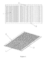
Figure 1 illustrates a diagram of the heating circuit composed of carbon and/or composite material tracks and two silver and/or metallic material bus bars, wherein the reference numbers illustrate:- 1 - carbon composite material and/or carbon;
- 2 - bus bar;
- 3 - bus bar.
-
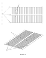
Figure 2 illustrates a heating circuit composed of carbon and/or carbon composite material tracks with larger dimensions and three silver and/or metallic material bus bars, wherein the reference numbers illustrate:- 1 - carbon composite material and/or carbon;
- 2 - bus bar.
-
Figure 3 illustrates a heating circuit composed by a continuous film and/or carbon composite material and silver and/or metallic material perpendicular bus bars, printed on both sides of the carbon film and/or composite material, wherein the reference numbers illustrate:- 1 - carbon composite material and/or carbon;
- 2 - bus bar.
- The use of two types of material with distinct physical and/or chemical and/or electrical properties, aims at the possibility of obtaining different electrical resistivity values after its processing. As resistive materials carbon pastes and/or carbon composite materials are used, capable of being processed by screen printing technology, and/or rotogravure and/or inkjet printing. These types of materials are used due to its higher sheet resistivity whose value is comprised between 10 and 100Ω/sq/mil, in order to enable a high efficiency of heating through Joule effect. Due to its high strength, the long circuit dimensioning has some limitations due to the loss of electric voltage seen across these, thereby influencing the desired heating.
- With the aim of reducing the electrical resistance of circuits with larger dimensions, silver and/or copper and/or aluminum tracks are printed, typically denominated bus bars, along the circuits. These conductive materials present low sheet resistivity, whose value is comprised between 5 and 40 mΩ/sq/mil and, therefore does not dissipate too much energy by Joule effect. Through this configuration the bus bars transport electric current uniformly to the various terminals of the carbon and/or carbon composite material tracks, thus permitting uniform release of thermal energy throughout the various tracks of the resistive material used.
- The dimensioning of the heating circuits is developed, based on the electrical resistivity of the materials used and the voltages that are typically used in many applications where they may be embedded. The printed heating circuit is powered by electric voltage DC (direct current) or AC (alternating current), its value being able to be adjusted in order to control the temperature thereof, or the environment in which it is embedded. The type of electrical voltage applied to the circuit varies with the intended final product, which can be a DC for heating solutions whose intended final application is related to the aeronautic, car and furniture industries, or AC for solutions related to the building industry. The use of printed heating circuits is possible in this range of electrical voltages, through the use of an AC-DC transformer which allows the conversion of alternating current into direct current.
- The operating temperature of the printed circuits can be monitored and controlled through the placement of temperature sensors in contact with these. The acquired data are recorded and/or worked by the electronic circuit wherein these are inserted, thereby enabling the temperature control in real time. In order to control and/or monitoring the printed heating circuits an association of these to an "on/off" circuit is carried out that allows to connect and/or disconnect the circuit, thereby maintaining the temperature on the surface between a maximum value and a minimum value.
- In another form of temperature control in the surface of the printed heating circuit, it is possible the association of a circuit that allows the current control that flows through the circuit, based on the values acquired by the temperature sensors whose placement was previously carried out in the surface.
- Given the wide range of existing applications for this type of heating circuits, it is necessary to use different types of connectors, so as not to damage the heating circuit. These are used for conducting the electrical current and/or signal between the control system, the power supply and the different circuits and/or components that compose the system. For this purpose, metallic connectors are used whose application may be carried out by crimping and/or welding allowing the quick coupling, and/or conductive metallic strips with adhesive properties whose application can be effected by gluing, and/or conductive metal wires fixed in the substrate by crimping, welding or both.
- Next, three geometries/designs/formats are presented based on the same principles of operation, varying however in functionality and dimensions from the heating circuits, which are not intended to limit the scope of the present application.
- In this geometry two silver and/or copper and/or aluminum tracks are printed, denominated bus bars (2, 3) and perpendicular tracks composed of carbon and/or carbon composite material (1). In this geometry the electric voltage is applied to the bus bars, with no significant heating of the conductive material used, because of its low electrical resistivity. The electric current flows between the two bus bars through the carbon and/or carbon composite material tracks (1) that, as have a high electrical resistance, generate a greater difficulty to the passage of electrical current than the silver tracks, generating this way the release of a greater amount of thermal energy through the Joule effect.
- In this geometry printed bus bars (2, 3) are used with lengths ranging from 50 to 5000 mm. For lengths greater than the maximum mentioned there is a drop in electrical voltage that affects the normal functioning of the heating circuits. The widths of these tracks are comprised between 2.5 and 15 mm and its thickness ranges between 2 and 100 µm.
- The distance between the bus bars (2, 3), varies between 40 and 100mm, with this value being dimensioned according to the specifications of the carbon and/or carbon composite material tracks. Depending on the dimensions, the bus bars have a total electrical resistance comprised between 0.1 and 10Ω, the sheet resistivity of the printed material being comprised between 5 and 40 mΩ/sq/mil.
- In this geometry, the printed carbon and/or carbon composite material tracks (1), have a length which may vary between 40 and 100mm, a width between 2.5 and 15mm, and a thickness comprised between 2 and 100 µm.
- The distance between the carbon and/or carbon composite material tracks (1), is equal to the width of the printed carbon and/or carbon composite material tracks, and may thus vary between 2.5 and 15 mm.
- Depending on the dimensions, carbon and/or carbon composite material tracks have a total electrical resistance comprised between 0.5 and 8KΩ, the sheet resistivity of the printed material being comprised between 10 and 100 Ω/sq/mil.
- In this geometry, carbon and/or composite material tracks (1) are printed with twice the length of the printed tracks of the geometry shown in
Figure 1 , and for three silver and/or copper and/or aluminum bus bars (2). This geometry allows the heating of a superior area, maintaining the temperature uniform across the surface, following the operation principle present in the geometry illustrated inFigure 1 . In this geometry the positive terminal of the power supply is applied to the exterior bus bars and the negative terminal is applied to the interior bus bar. - In this geometry, printed bus bars (2) are used with lengths ranging from 50 to 5000 mm. For lengths greater than the maximum mentioned there is a drop in electrical voltage that affects the normal functioning of the heating circuits. The widths of these tracks are comprised between 2.5 and 15 mm, and its thickness ranges between 2 and 100 µm.
- The distance between the bus bars (2), varies between 40 and 100 mm, this value should be dimensioned according to the specifications of the printed carbon and/or carbon composite material tracks.
- Depending on the dimensions, the printed bus bars have a total electrical resistance comprised between 0.01 and 10 Ω, the sheet resistivity of the printed material being comprised between 5 and 40 mΩ/sq/mil.
- In this geometry, the printed carbon and/or carbon composite material tracks (1), have a length which may vary between 80 and 200mm, a width between 2.5 and 15 mm, and a thickness comprised between 2 and 100 µm.
- The distance between the printed carbon and/or carbon composite material tracks (1), is equal to the width of the carbon and/or carbon composite materials tracks, for this reason ranging between 2.5 and 15 mm.
- Depending on the dimensions, the printed carbon and/or carbon composite materials tracks have a total electrical resistance comprised between 1 and 16 KΩ, the sheet resistivity of the printed material being comprised between 10 and 100 Ω/sq/mil.
- In this geometry, silver and/or copper and/or aluminum bus bars (2) are printed, being subsequently printed a continuous film of carbon and/or carbon composite materials (1). Over the carbon film and/or carbon composite materials, silver and/or copper and/or aluminum bus bars are printed perpendicular to the previously printed ones. The main purpose of the geometry used for printing perpendicular bus bars is to allow the subsequent cutting of the printed circuits in two different directions, without any interruption in the conduction of the electric current through the bus bars. In this way it is ensured that, regardless of the cut that takes place, there will be conduction of electric current through the upper and/or lower bus bars. The use of a carbon continuous film and/or carbon composite materials, has as main advantage the high temperature uniformity obtained along the entire surface of the device. However, this device is not as flexible as the devices composed of carbon and/or composite material tracks.
- In this geometry, printed bus bars are used (2) with lengths ranging between 50 and 500 mm. For lengths greater than the maximum mentioned there is a drop of electrical voltage that affects the normal functioning of the heating circuits. The widths of these tracks are comprised between 2.5 and 15 mm, and its thickness ranges between 2 and 100 µm.
- The distance between the printed bus bars (2) varies between 40 and 100mm, this value should be dimensioned according to the specifications of the printed carbon tracks and/or carbon composite materials.
- Depending on the dimensions, the printed bus bars have a total electrical resistance comprised between 0.01 and 35 Ω, the sheet resistivity of the printed material being comprised between 5 and 40 mΩ/sq/mil.
- In this geometry the printed carbon film and/or carbon composite materials (1), have a length which may vary between 80 and 200 mm, a width between 2.5 and 15 mm, and a thickness comprised between 2 and 100 µm.
- Depending on the dimensions, printed carbon films and/or carbon composite material have a total electrical resistance comprised between 10 and 2000Ω, the sheet resistivity of the printed material being comprised between 10 and 100 Ω/sq/mil.
- The two materials that compose the heating circuits are printed by screen printing and/or rotogravure and/or inkjet printing on roll to roll and/or sheet to sheet systems, being the chosen printing technology, tailored to the substrate used.
- In the screen printing technology, the ink is forced to pass to the substrate through a frame which is perforated with the pattern that one wants to print out, this being constituted by polyester or metal. In order to force the passage of the ink, a squeegee is used composed of a natural or synthetic rubber, normally flexible polychloroprene or polyurethane. The printing process of the heating circuits by the screen printing technology may be carried out on a sheet to sheet and/or roll to roll systems. Hereunder the steps for printing a sheet to sheet system on flexible and/or rigid substrates are presented:
- 1. Printing of the carbon paste and/or carbon composite material to the resistive tracks and/or films over the flexible and/or rigid substrate;
- 2.Thermal curing of the pattern and/or carbon film and/or carbon composite material at temperatures comprised between 100 and 150°C, for 10 to 20 minutes;
- 3. Printing silver and/or copper and/or aluminum tracks over the flexible and/or rigid substrate;
- 4. Thermal curing of the silver and/or copper and/or aluminum tracks at temperatures comprised between 100 and 150°C, for 10 to 20 minutes.
- Printing of the heating circuits on a roll to roll system, on flexible substrates follows the following steps:
- 1. Printing of the carbon tracks and/or films and/or carbon composite material to the resistive tracks and/or films at speeds comprised between 0.1 and 10 m/min over the flexible substrate;
- 2. Thermal curing of the carbon pattern and/or carbon film and/or carbon composite material at temperatures comprised between 100 and 150°C, at speeds comprised between 0.1 and 10 m/min;
- 3. Printing silver and/or copper and/or aluminum tracks at speeds comprised between 0.1 and 10 m/min over the flexible substrate;
- 4. Thermal curing of silver and/or copper and/or aluminum tracks at temperatures comprised between 100 and 150°C at speeds comprised between 0.1 and 10 m/min;
- The dimensions of the printed circuits, and the tracks that compose them, are defined by the frame used to make the printing. In this technique, the amount of material which is printed is defined by the characteristics of the frame and the processing parameters used. The curing of the material after the printing is done in dryers/ovens with ventilation.
- In the rotogravure technology on roll to roll systems, the pattern that one wants to print out is previously engraved in a stainless steel cylinder. Subsequently it is forced to pass in a bath with the ink and/or paste that is intended to print, in order to ensure that all of it is coated with it. Prior to the printing, the ink and/or paste in excess that remains in the non-engraved roll surface is withdrawn by a metal blade (or a fabric) which is in permanent contact with the roll surface. A hydrodynamic counter pressure is exerted upon the blade, being this mainly caused by the contact angle of these, the velocity of the compression and of the viscosity of the material used, subsequently the engraved pattern is printed on the flexible substrate that is in motion on the roll to roll system.
- The printing process of the heating circuits by the rotogravure technology on the roll to roll system on flexible substrates, follows the following steps:
- 1. Printing of the carbon tracks and/or films and/or carbon composite material for the resistive tracks and/or films on the flexible substrate, at speeds comprised between 0.1 and 1 m/min;
- 2. Thermal curing of the carbon pattern and/or film and/or carbon composite material at temperatures comprised between 100 and 150°C at speeds comprised between 0.1 and 1 m/min;
- 3. Printing of the silver and/or copper and/or aluminum tracks in the flexible substrate, at speeds comprised between 0.1 and 1 m/min;
- 4. Thermal curing of the silver and/or copper and/or aluminum tracks at temperatures comprised between 100 and 150°C at speeds comprised between 0.1 and 1 m/min.
- In the inkjet printing technology the pattern to be printed is previously drawn in digital format, being subsequently sent the information through electric pulses to the print head of the equipment, whose operation is based on transducers and/or piezoelectric actuators. This is responsible for the printing of metallic conductive materials and/or non-metallic resistive materials.
- The printing process of the heating circuits for the inkjet printing technology on a sheet to sheet system on flexible and/or rigid substrates follows the following steps:
- 1. Digital drawing of the heating circuit which is intended to print;
- 2. Printing of the carbon tracks and/or films and/or carbon composite material to the resistive tracks and/or films on the flexible and/or rigid substrate;
- 3.Thermal curing of the carbon pattern and/or film and/or carbon composite material at temperatures comprised between 100 and 150°C, for 10 to 20 minutes;
- 4. Printing of the silver and/or copper and/or aluminum tracks in the flexible and/or rigid substrate;
- 5.Thermal curing of the silver and/or copper and/or aluminum tracks at temperatures comprised between 100 and 150°C, for 10 to 20 minutes.
- Printing of the heating circuits can be carried out on flexible substrates such as polyethylene terephthalate (PET), and/or polyethylene naphthalate (PEN), and/or cork, and/or thermoplastic polyolefin (TPO) and/or coated meshes with polymeric films typically compatible with roll to roll systems, or rigid substrates such as concrete, and/or glass and/or ceramic, and/or wood agglomerates typically compatible with sheet to sheet systems. These substrates resist the curing temperature of the metallic and non-metallic materials, usually comprised between 100 and 150°C with an exposure time at temperatures comprised between 10 and 20 minutes, which constitute the heating circuits.
- The resistive non-metallic materials used are based on carbon pastes and/or carbon composite materials. These have a viscosity comprised between 5 and 250 Pa.s, a sheet resistivity comprised between 10 and 100 Ω/sq/mil, and are thermally cured at a temperature between 100 and 150°C, for 10 to 20 minutes.
- The materials used in the printing of the resistive patterns have graphite in its composition (10-15 weight %) and/or carbon black (10-15 weight %) and/or monomethyl ether of dipropylene glycol (60-65% weight %) and/or bisphenol-a-epichlorohydrin (15-20 weight %) and/or oil distillates (5-15 weight %) being their percentages altered in order to obtain the desired electrical resistivities. The use of oil distillates is optional, however its introduction allows obtaining a higher electrical, mechanical and chemical stability of the material developed after its printing and curing. On the occasion of its introduction it should be reduced the same percentage to the bisphenol-a-epichlorohydrin.
- The metallic conductor materials used are based on silver and/or copper and/or aluminum. These have a viscosity comprised between 5 and 200 Pa.s, a sheet resistivity comprised between 5 and 40 mΩ/sq/mil, and thermally cure at a temperature between 100 and 150°C, for 10 to 20 minutes.
- The materials used in printing of the conductive tracks have aluminum in its composition (60-85 weight %) or silver (60-90 weight %) or copper (60-90 weight %) and/or methyl-2-methoxyethoxy) propanol (20-30 weight %) and/or 2-(2 ethoxyethyl) ethyl acetate (7-10 weight %), being their percentages altered in order to obtain the desired electrical resistivities.
- The material used in the screen of the screen printing is composed of polyethylene terephthalate (PET) and/or metal, having between 50 and 110 wires per centimeter whose diameters can range between 30 and 60 µm.
- As final objects printed heating circuits are obtained by screen printing and/or rotogravure and/or inkjet printing on a sheet to sheet and/or roll to roll systems, in flexible and/or rigid substrates. The printed heating circuits are composed of metallic and/or nonmetallic materials, such as silver and/or aluminum and/or copper and/or carbon and/or carbon composite materials and have three geometries/designs/formats for heating of various types of surfaces. The circuits presented offer different advantages, being noteworthy that the possibility to obtain a larger heating area and/or the opportunity to perform the sectioning to the required size of the circuit in two different directions, without loss of any functionality.
- The temperature obtained on the surface of the printed circuits depends on the electric voltage applied to the terminals thereof, the dimensions of the printed circuit board and its respective lines, the thickness of the printed films, the substrate in which is printed, the materials used in its processing, the type of association (series or parallel) between the various circuit boards and the environment in which the heating circuit is embedded and/or laminated and/or printed.
- This type of devices whose application purpose is heating, present several advantages such as low weight, small thickness and high flexibility, and can be easily laminated with other type of materials. Since they are placed close to the surfaces to heat, the dissipated power at the surface will be lower, resulting in lower energy consumptions, when compared to other heating systems.
Claims (15)
- Printed heating device comprises:- bus bars that comprise materials with sheet resistivities comprised between 5 and 40 mΩ/sq/mil;- printed tracks that comprise materials with sheet resistivities comprised between 10 and 100 Ω/sq/mil;- printed connections between the modules of the heating circuits;- a flexible or rigid substrate.
- Printed heating device according to the preceding claim, in which additionally an electronic control system is coupled, comprises:- a power supply for the circuits;- temperature sensors for monitoring;- electronic temperature control system;- barrier film for electrical and mechanical protection.
- Printed heating device according to any one of the preceding claims, wherein the bus bars present lengths ranging between 50 and 5000 mm.
- Printed heating device according to any one of the preceding claims, wherein the tracks present a length that may vary between 40 and 200mm, a width comprised between 2.5 and 15 mm and a thickness that is comprised between the 2 and the 100 µm.
- Printed heating device according to any one of the preceding claims, wherein the distance between the bus bars is comprised between 40 and 100 mm.
- Printed heating device according to any one of the preceding claims, wherein the distance between tracks is comprised between 2.5 and 15 mm.
- Printed heating device according to any one of the preceding claims, wherein the flexible substrate is carried out in polyethylene terephthalate (PET), and/or polyethylene naphthalate (PEN), and/or cork, and/or thermoplastic polyolefin (TPO) and/or meshes coated with polymeric films.
- Printed heating device according to any one of the preceding claims, wherein the rigid substrate is carried out on concrete, and/or glass and/or ceramic, and/or wood agglomerates typically compatible with sheet to sheet systems.
- Printed heating device according to any one of the preceding claims, wherein the materials used in the printing of the resistive tracks and/or films comprise the following composition:- graphite (10-15 weight %);- carbon black (10-15 weight %);- monomethyl ether of dipropylene glycol (60-65% weight %);- bisphenol-a-epichlorohydrin (15-20 weight %);- oil distillates (5-15 weight %).
- Printed heating device according to any one of claims 1 to 8, wherein the materials used in the printing of conductive tracks comprise the following composition:- aluminum (60-85 weight %) or silver (60-90 weight %) or copper (60-90 weight %);- methyl-2-methoxyethoxy) propanol (20-30 weight %);- 2-(2 ethoxyetoxy) ethyl acetate (7-10 weight %).
- Method for printing on a sheet to sheet system on flexible and/or rigid substrates of the heating device described in claims 1 to 10 comprises the following steps:- Printing of the carbon paste and/or carbon composite material for the resistive tracks and/or films over the flexible and/or rigid substrate;- Thermal curing of the carbon pattern and/or film and/or carbon composite material at temperatures comprised between 100 and 150°C, for 10 to 20 minutes;- Printing of the silver and/or copper and/or aluminum tracks over the flexible and/or rigid substrate;- Thermal curing of the silver and/or copper and/or aluminum tracks at temperatures comprised between 100 and 150°C, for 10 to 20 minutes.
- Method for printing on a roll to roll system on flexible substrates of the heating device described in claims 1 to 10 comprises the following steps:- Printing of the carbon tracks and/or carbon films and/or carbon composite material to the resistive tracks and/or films at speeds comprised between 0.1 and 10 m/min over the flexible substrate;- Thermal curing of the carbon pattern and/or film and/or carbon composite material at temperatures comprised between 100 and 150°C, at speeds comprised between 0.1 and 10 m/min;- Printing of the silver and/or copper and/or aluminum tracks at speeds comprised between 0.1 and 10 m/min on the flexible substrate;- Thermal curing of the silver and/or copper and/or aluminum tracks at temperatures comprised between 100 and 150°C, at speeds comprised between 0.1 and 10 m/min.
- Method of printing by the rotogravure technology on a roll to roll system for obtaining the heating device described in claims 1 to 10 comprises the following steps:- Printing of the carbon tracks and/or films and/or carbon composite material for the resistive tracks and/or films on the flexible substrate, at speeds comprised between 0.1 and 1 m/min;- Thermal curing of the carbon pattern and/or film and/or carbon composite material at temperatures comprised between 100 and 150°C, at speeds comprised between 0.1 and 1 m/min;- Printing of the silver and/or copper and/or aluminum tracks in the flexible substrate at speeds comprised between 0.1 and 1 m/min;- Thermal curing of the silver and/or copper and/or aluminum tracks at temperatures comprised between 100 and 150°C, at speeds comprised between 0.1 and 1 m/min.
- Printing method by the inkjet technology on a sheet to sheet system for obtaining the heating device described in claims 1 to 10 comprises the following steps:- Elaboration of the digital design of the heating circuit which is intended to print;- Printing of the carbon tracks and/or carbon films and/or carbon composite material for the resistive tracks and/or films on the flexible and/or rigid substrate;- Thermal curing of the carbon pattern and/or film and/or carbon composite material at temperatures comprised between 100 and 150°C, for 10 to 20 minutes;- Printing of the silver and/or copper and/or aluminum tracks on the flexible substrate on the flexible and/or rigid substrate;- Thermal curing of the silver and/or copper and/or aluminum tracks at temperatures comprised between 100 and 150°C, for 10 to 20 minutes.
- Use of the heating device described in claims 1 to 10 in heating indoor and outdoor floors, on chairs, sofas and seats, in particular on the seats and supports for legs and arms and also in the vehicles' doors and dashboards.
Applications Claiming Priority (2)
| Application Number | Priority Date | Filing Date | Title |
|---|---|---|---|
| PT10649312 | 2012-08-08 | ||
| PCT/IB2013/056498 WO2014024165A2 (en) | 2012-08-08 | 2013-08-08 | Heating device, respective printing and using methods |
Publications (3)
| Publication Number | Publication Date |
|---|---|
| EP2884818A2 true EP2884818A2 (en) | 2015-06-17 |
| EP2884818B1 EP2884818B1 (en) | 2023-06-07 |
| EP2884818C0 EP2884818C0 (en) | 2023-06-07 |
Family
ID=49328595
Family Applications (1)
| Application Number | Title | Priority Date | Filing Date |
|---|---|---|---|
| EP13774822.4A Active EP2884818B1 (en) | 2012-08-08 | 2013-08-08 | Heating device, respective printing and using methods |
Country Status (2)
| Country | Link |
|---|---|
| EP (1) | EP2884818B1 (en) |
| WO (1) | WO2014024165A2 (en) |
Cited By (9)
| Publication number | Priority date | Publication date | Assignee | Title |
|---|---|---|---|---|
| PT108334A (en) * | 2015-03-31 | 2016-09-30 | Amorim Revestimentos Sa | PROCESS OF PRODUCTION OF A HEATING SYSTEM COMPREHENDING A SUBSTRATE OF CORK AGGLOMERATE AND HEATING CIRCUITS PRINTED |
| WO2017176208A1 (en) * | 2016-04-05 | 2017-10-12 | Dou Yee Enterprises (S) Pte Ltd | Self adhesive heating tape and manufacturing process thereof |
| CN110107405A (en) * | 2019-05-22 | 2019-08-09 | 江鹏 | A kind of engine charge protective grille |
| WO2020056128A1 (en) * | 2018-09-13 | 2020-03-19 | De Luca Oven Technologies, Llc | Multi planar heater element for use in a high-speed oven |
| WO2020056131A1 (en) * | 2018-09-13 | 2020-03-19 | De Luca Oven Technologies, Llc | Heater element incorporating primary conductor for use in a high-speed oven |
| EP3641492A1 (en) * | 2018-10-16 | 2020-04-22 | Goodrich Corporation | Method of using printed highly flexible conductive ink bus bars to transfer power to heated components |
| CN112397107A (en) * | 2019-08-16 | 2021-02-23 | 神讯电脑(昆山)有限公司 | Heating and radiating structure of storage device |
| FR3102908A1 (en) * | 2019-11-06 | 2021-05-07 | Valeo Systemes Thermiques | Heating structure for motor vehicle |
| CN113993430A (en) * | 2019-02-06 | 2022-01-28 | 德卢卡炉灶技术有限责任公司 | Multi-planar heating element for high speed ovens including novel tensioning system |
Families Citing this family (5)
| Publication number | Priority date | Publication date | Assignee | Title |
|---|---|---|---|---|
| PT107488B (en) | 2014-02-27 | 2019-01-10 | Cmp Cimentos Maceira E Pataias S A | SYSTEM FOR ACTIVE ENERGY MANAGEMENT IN CONCRETE WALLS AND / OR FLOORS |
| CN104553587A (en) * | 2015-01-08 | 2015-04-29 | 昆山金利表面材料应用科技股份有限公司 | Heating type decorative film |
| US11376811B2 (en) | 2018-07-03 | 2022-07-05 | Goodrich Corporation | Impact and knife cut resistant pre-impregnated woven fabric for aircraft heated floor panels |
| US20200015325A1 (en) * | 2018-07-03 | 2020-01-09 | Goodrich Corporation | Fusion welded positive temperature coefficient heater assemblies |
| CN113645723B (en) * | 2021-08-09 | 2024-08-23 | 山东启原纳米科技有限公司 | Intelligent flexible electric heating system and preparation method thereof |
Family Cites Families (8)
| Publication number | Priority date | Publication date | Assignee | Title |
|---|---|---|---|---|
| WO1997015171A2 (en) | 1995-10-17 | 1997-04-24 | Magnus Kluge | Electrical resistance heating for air conditioning in dwellings and buildings |
| US6512203B2 (en) * | 1999-05-06 | 2003-01-28 | Polymore Circuit Technologies | Polymer thick film heating element on a glass substrate |
| EP1846293B1 (en) * | 2005-02-09 | 2009-04-29 | Qinetiq Limited | Electrotermal heater for ice protection of aerodynamic surfaces and its method of producing |
| WO2007021528A1 (en) | 2005-08-17 | 2007-02-22 | Thermion Systems International | Heaters with perforated bus bars |
| CN102523642B (en) | 2005-12-29 | 2015-06-17 | 埃克阿泰克有限责任公司 | Window defrosting assembly |
| US20080099456A1 (en) * | 2006-10-25 | 2008-05-01 | Schwenke Robert A | Dispensing method for variable line volume |
| JP2011514647A (en) * | 2008-03-17 | 2011-05-06 | エルジー・ケム・リミテッド | Heating element and method for manufacturing the same |
| DE202010009208U1 (en) * | 2010-06-17 | 2010-09-16 | Futurecarbon Gmbh | Flexible heating element |
-
2013
- 2013-08-08 WO PCT/IB2013/056498 patent/WO2014024165A2/en not_active Ceased
- 2013-08-08 EP EP13774822.4A patent/EP2884818B1/en active Active
Cited By (16)
| Publication number | Priority date | Publication date | Assignee | Title |
|---|---|---|---|---|
| PT108334A (en) * | 2015-03-31 | 2016-09-30 | Amorim Revestimentos Sa | PROCESS OF PRODUCTION OF A HEATING SYSTEM COMPREHENDING A SUBSTRATE OF CORK AGGLOMERATE AND HEATING CIRCUITS PRINTED |
| PT108334B (en) * | 2015-03-31 | 2017-08-30 | Amorim Revestimentos Sa | PROCESS OF PRODUCTION OF A HEATING SYSTEM COMPREHENDING A SUBSTRATE OF CORK AGGLOMERATE AND HEATING CIRCUITS PRINTED |
| WO2017176208A1 (en) * | 2016-04-05 | 2017-10-12 | Dou Yee Enterprises (S) Pte Ltd | Self adhesive heating tape and manufacturing process thereof |
| US20220053612A1 (en) * | 2018-09-13 | 2022-02-17 | De Luca Oven Technologies, Llc | Heater element incorporating primary conductor for use in a high-speed oven |
| WO2020056128A1 (en) * | 2018-09-13 | 2020-03-19 | De Luca Oven Technologies, Llc | Multi planar heater element for use in a high-speed oven |
| WO2020056131A1 (en) * | 2018-09-13 | 2020-03-19 | De Luca Oven Technologies, Llc | Heater element incorporating primary conductor for use in a high-speed oven |
| US11242151B2 (en) | 2018-10-16 | 2022-02-08 | Goodrich Corporation | Method of using printed highly flexible conductive ink bus bars to transfer power to heated components |
| CN111056017A (en) * | 2018-10-16 | 2020-04-24 | 古德里奇公司 | Method of transferring power to a heated component using a printed highly flexible conductive ink bus bar |
| EP3641492A1 (en) * | 2018-10-16 | 2020-04-22 | Goodrich Corporation | Method of using printed highly flexible conductive ink bus bars to transfer power to heated components |
| CN111056017B (en) * | 2018-10-16 | 2024-06-07 | 古德里奇公司 | Resistance heating circuit for heated or anti-icing aircraft structure and method of making the same |
| CN113993430A (en) * | 2019-02-06 | 2022-01-28 | 德卢卡炉灶技术有限责任公司 | Multi-planar heating element for high speed ovens including novel tensioning system |
| CN113993430B (en) * | 2019-02-06 | 2024-05-17 | 德卢卡炉灶技术有限责任公司 | Multi-planar heating element for a high speed oven including a tensioning system |
| CN110107405B (en) * | 2019-05-22 | 2021-05-28 | 江鹏 | Air inlet protective grid of helicopter engine |
| CN110107405A (en) * | 2019-05-22 | 2019-08-09 | 江鹏 | A kind of engine charge protective grille |
| CN112397107A (en) * | 2019-08-16 | 2021-02-23 | 神讯电脑(昆山)有限公司 | Heating and radiating structure of storage device |
| FR3102908A1 (en) * | 2019-11-06 | 2021-05-07 | Valeo Systemes Thermiques | Heating structure for motor vehicle |
Also Published As
| Publication number | Publication date |
|---|---|
| WO2014024165A9 (en) | 2014-04-10 |
| WO2014024165A2 (en) | 2014-02-13 |
| EP2884818B1 (en) | 2023-06-07 |
| EP2884818C0 (en) | 2023-06-07 |
Similar Documents
| Publication | Publication Date | Title |
|---|---|---|
| EP2884818B1 (en) | Heating device, respective printing and using methods | |
| CN107635296B (en) | Compound flexible heating film subassembly of graphite alkene silver nanometer line | |
| CA2989692C (en) | Printed heater elements integrated in construction materials | |
| JP5452443B2 (en) | Conductive pattern forming substrate | |
| KR102671577B1 (en) | Printable molecular ink | |
| US20200113019A1 (en) | Electric heating device | |
| EP2483896B1 (en) | Positive temperature coefficient heating elements and their manufacturing | |
| KR20140088169A (en) | Conductive pattern formation method | |
| JP2014191894A (en) | Transparent electroconductive film and touch panel | |
| WO2011116179A1 (en) | Film based heating device and methods relating thereto | |
| US11089658B2 (en) | Heating element | |
| KR102049508B1 (en) | The plate heating element applied a coating fabric having an even surface and the manufacturing method thereof | |
| Wei et al. | Laser curing of screen and inkjet printed conductors on flexible substrates | |
| CN104602372A (en) | Low-temperature radiation electro-thermal film | |
| JP4921995B2 (en) | Planar heating element and manufacturing method thereof | |
| EP4301090A1 (en) | Natural stone panel with an integrated heating system and manufacturing method thereof | |
| JP2024057914A (en) | Plane heating element, hot air supply device, and inkjet printer | |
| US11937342B2 (en) | Spot heater | |
| KR20060073119A (en) | Planar heating element with excellent resistance characteristics | |
| EP4548710A1 (en) | Natural stone panel with an integrated heating system and manufacturing method thereof | |
| KR101869326B1 (en) | Direct-contactable conductive adhesive tape using nanometal power and manufacturing method thereof | |
| CN110392457A (en) | A kind of low-voltage electric heating film | |
| EP4590077A1 (en) | Method for producing conductive base material, method for producing electronic device, method for producing electromagnetic shield film, method for producing sheet-like heating element and conductive composition | |
| CN1598411A (en) | Fuse for short-circuit protection and floor heating device using the fuse | |
| KR101260175B1 (en) | Conductive composition for heating product and plane heating product comprising the same |
Legal Events
| Date | Code | Title | Description |
|---|---|---|---|
| PUAI | Public reference made under article 153(3) epc to a published international application that has entered the european phase |
Free format text: ORIGINAL CODE: 0009012 |
|
| 17P | Request for examination filed |
Effective date: 20150306 |
|
| AK | Designated contracting states |
Kind code of ref document: A2 Designated state(s): AL AT BE BG CH CY CZ DE DK EE ES FI FR GB GR HR HU IE IS IT LI LT LU LV MC MK MT NL NO PL PT RO RS SE SI SK SM TR |
|
| AX | Request for extension of the european patent |
Extension state: BA ME |
|
| DAX | Request for extension of the european patent (deleted) | ||
| 17Q | First examination report despatched |
Effective date: 20160525 |
|
| STAA | Information on the status of an ep patent application or granted ep patent |
Free format text: STATUS: EXAMINATION IS IN PROGRESS |
|
| RAP1 | Party data changed (applicant data changed or rights of an application transferred) |
Owner name: CENTITVC - CENTRO DE NANOTECNOLOGIA E MATERIAIS TE |
|
| GRAP | Despatch of communication of intention to grant a patent |
Free format text: ORIGINAL CODE: EPIDOSNIGR1 |
|
| STAA | Information on the status of an ep patent application or granted ep patent |
Free format text: STATUS: GRANT OF PATENT IS INTENDED |
|
| INTG | Intention to grant announced |
Effective date: 20211222 |
|
| GRAJ | Information related to disapproval of communication of intention to grant by the applicant or resumption of examination proceedings by the epo deleted |
Free format text: ORIGINAL CODE: EPIDOSDIGR1 |
|
| STAA | Information on the status of an ep patent application or granted ep patent |
Free format text: STATUS: EXAMINATION IS IN PROGRESS |
|
| INTC | Intention to grant announced (deleted) | ||
| GRAP | Despatch of communication of intention to grant a patent |
Free format text: ORIGINAL CODE: EPIDOSNIGR1 |
|
| STAA | Information on the status of an ep patent application or granted ep patent |
Free format text: STATUS: GRANT OF PATENT IS INTENDED |
|
| INTG | Intention to grant announced |
Effective date: 20220610 |
|
| GRAJ | Information related to disapproval of communication of intention to grant by the applicant or resumption of examination proceedings by the epo deleted |
Free format text: ORIGINAL CODE: EPIDOSDIGR1 |
|
| STAA | Information on the status of an ep patent application or granted ep patent |
Free format text: STATUS: EXAMINATION IS IN PROGRESS |
|
| GRAS | Grant fee paid |
Free format text: ORIGINAL CODE: EPIDOSNIGR3 |
|
| STAA | Information on the status of an ep patent application or granted ep patent |
Free format text: STATUS: GRANT OF PATENT IS INTENDED |
|
| GRAP | Despatch of communication of intention to grant a patent |
Free format text: ORIGINAL CODE: EPIDOSNIGR1 |
|
| INTC | Intention to grant announced (deleted) | ||
| INTG | Intention to grant announced |
Effective date: 20221108 |
|
| GRAA | (expected) grant |
Free format text: ORIGINAL CODE: 0009210 |
|
| STAA | Information on the status of an ep patent application or granted ep patent |
Free format text: STATUS: THE PATENT HAS BEEN GRANTED |
|
| AK | Designated contracting states |
Kind code of ref document: B1 Designated state(s): AL AT BE BG CH CY CZ DE DK EE ES FI FR GB GR HR HU IE IS IT LI LT LU LV MC MK MT NL NO PL PT RO RS SE SI SK SM TR |
|
| REG | Reference to a national code |
Ref country code: GB Ref legal event code: FG4D |
|
| REG | Reference to a national code |
Ref country code: CH Ref legal event code: EP Ref country code: AT Ref legal event code: REF Ref document number: 1578423 Country of ref document: AT Kind code of ref document: T Effective date: 20230615 |
|
| REG | Reference to a national code |
Ref country code: DE Ref legal event code: R096 Ref document number: 602013083941 Country of ref document: DE |
|
| U01 | Request for unitary effect filed |
Effective date: 20230630 |
|
| U07 | Unitary effect registered |
Designated state(s): AT BE BG DE DK EE FI FR IT LT LU LV MT NL PT SE SI Effective date: 20230710 |
|
| REG | Reference to a national code |
Ref country code: LT Ref legal event code: MG9D |
|
| PG25 | Lapsed in a contracting state [announced via postgrant information from national office to epo] |
Ref country code: NO Free format text: LAPSE BECAUSE OF FAILURE TO SUBMIT A TRANSLATION OF THE DESCRIPTION OR TO PAY THE FEE WITHIN THE PRESCRIBED TIME-LIMIT Effective date: 20230907 Ref country code: ES Free format text: LAPSE BECAUSE OF FAILURE TO SUBMIT A TRANSLATION OF THE DESCRIPTION OR TO PAY THE FEE WITHIN THE PRESCRIBED TIME-LIMIT Effective date: 20230607 |
|
| U20 | Renewal fee for the european patent with unitary effect paid |
Year of fee payment: 11 Effective date: 20231009 |
|
| PG25 | Lapsed in a contracting state [announced via postgrant information from national office to epo] |
Ref country code: RS Free format text: LAPSE BECAUSE OF FAILURE TO SUBMIT A TRANSLATION OF THE DESCRIPTION OR TO PAY THE FEE WITHIN THE PRESCRIBED TIME-LIMIT Effective date: 20230607 Ref country code: HR Free format text: LAPSE BECAUSE OF FAILURE TO SUBMIT A TRANSLATION OF THE DESCRIPTION OR TO PAY THE FEE WITHIN THE PRESCRIBED TIME-LIMIT Effective date: 20230607 Ref country code: GR Free format text: LAPSE BECAUSE OF FAILURE TO SUBMIT A TRANSLATION OF THE DESCRIPTION OR TO PAY THE FEE WITHIN THE PRESCRIBED TIME-LIMIT Effective date: 20230908 |
|
| PG25 | Lapsed in a contracting state [announced via postgrant information from national office to epo] |
Ref country code: SK Free format text: LAPSE BECAUSE OF FAILURE TO SUBMIT A TRANSLATION OF THE DESCRIPTION OR TO PAY THE FEE WITHIN THE PRESCRIBED TIME-LIMIT Effective date: 20230607 |
|
| PG25 | Lapsed in a contracting state [announced via postgrant information from national office to epo] |
Ref country code: IS Free format text: LAPSE BECAUSE OF FAILURE TO SUBMIT A TRANSLATION OF THE DESCRIPTION OR TO PAY THE FEE WITHIN THE PRESCRIBED TIME-LIMIT Effective date: 20231007 |
|
| PG25 | Lapsed in a contracting state [announced via postgrant information from national office to epo] |
Ref country code: SM Free format text: LAPSE BECAUSE OF FAILURE TO SUBMIT A TRANSLATION OF THE DESCRIPTION OR TO PAY THE FEE WITHIN THE PRESCRIBED TIME-LIMIT Effective date: 20230607 Ref country code: SK Free format text: LAPSE BECAUSE OF FAILURE TO SUBMIT A TRANSLATION OF THE DESCRIPTION OR TO PAY THE FEE WITHIN THE PRESCRIBED TIME-LIMIT Effective date: 20230607 Ref country code: RO Free format text: LAPSE BECAUSE OF FAILURE TO SUBMIT A TRANSLATION OF THE DESCRIPTION OR TO PAY THE FEE WITHIN THE PRESCRIBED TIME-LIMIT Effective date: 20230607 Ref country code: IS Free format text: LAPSE BECAUSE OF FAILURE TO SUBMIT A TRANSLATION OF THE DESCRIPTION OR TO PAY THE FEE WITHIN THE PRESCRIBED TIME-LIMIT Effective date: 20231007 Ref country code: CZ Free format text: LAPSE BECAUSE OF FAILURE TO SUBMIT A TRANSLATION OF THE DESCRIPTION OR TO PAY THE FEE WITHIN THE PRESCRIBED TIME-LIMIT Effective date: 20230607 |
|
| PG25 | Lapsed in a contracting state [announced via postgrant information from national office to epo] |
Ref country code: PL Free format text: LAPSE BECAUSE OF FAILURE TO SUBMIT A TRANSLATION OF THE DESCRIPTION OR TO PAY THE FEE WITHIN THE PRESCRIBED TIME-LIMIT Effective date: 20230607 |
|
| REG | Reference to a national code |
Ref country code: DE Ref legal event code: R097 Ref document number: 602013083941 Country of ref document: DE |
|
| PG25 | Lapsed in a contracting state [announced via postgrant information from national office to epo] |
Ref country code: MC Free format text: LAPSE BECAUSE OF FAILURE TO SUBMIT A TRANSLATION OF THE DESCRIPTION OR TO PAY THE FEE WITHIN THE PRESCRIBED TIME-LIMIT Effective date: 20230607 |
|
| REG | Reference to a national code |
Ref country code: CH Ref legal event code: PL |
|
| PG25 | Lapsed in a contracting state [announced via postgrant information from national office to epo] |
Ref country code: MC Free format text: LAPSE BECAUSE OF FAILURE TO SUBMIT A TRANSLATION OF THE DESCRIPTION OR TO PAY THE FEE WITHIN THE PRESCRIBED TIME-LIMIT Effective date: 20230607 |
|
| PLBE | No opposition filed within time limit |
Free format text: ORIGINAL CODE: 0009261 |
|
| STAA | Information on the status of an ep patent application or granted ep patent |
Free format text: STATUS: NO OPPOSITION FILED WITHIN TIME LIMIT |
|
| PG25 | Lapsed in a contracting state [announced via postgrant information from national office to epo] |
Ref country code: CH Free format text: LAPSE BECAUSE OF NON-PAYMENT OF DUE FEES Effective date: 20230831 |
|
| 26N | No opposition filed |
Effective date: 20240308 |
|
| REG | Reference to a national code |
Ref country code: IE Ref legal event code: MM4A |
|
| GBPC | Gb: european patent ceased through non-payment of renewal fee |
Effective date: 20230907 |
|
| PG25 | Lapsed in a contracting state [announced via postgrant information from national office to epo] |
Ref country code: IE Free format text: LAPSE BECAUSE OF NON-PAYMENT OF DUE FEES Effective date: 20230808 |
|
| PG25 | Lapsed in a contracting state [announced via postgrant information from national office to epo] |
Ref country code: GB Free format text: LAPSE BECAUSE OF NON-PAYMENT OF DUE FEES Effective date: 20230907 |
|
| PG25 | Lapsed in a contracting state [announced via postgrant information from national office to epo] |
Ref country code: IE Free format text: LAPSE BECAUSE OF NON-PAYMENT OF DUE FEES Effective date: 20230808 Ref country code: GB Free format text: LAPSE BECAUSE OF NON-PAYMENT OF DUE FEES Effective date: 20230907 |
|
| U20 | Renewal fee for the european patent with unitary effect paid |
Year of fee payment: 12 Effective date: 20240807 |
|
| PG25 | Lapsed in a contracting state [announced via postgrant information from national office to epo] |
Ref country code: CY Free format text: LAPSE BECAUSE OF FAILURE TO SUBMIT A TRANSLATION OF THE DESCRIPTION OR TO PAY THE FEE WITHIN THE PRESCRIBED TIME-LIMIT; INVALID AB INITIO Effective date: 20130808 |
|
| PG25 | Lapsed in a contracting state [announced via postgrant information from national office to epo] |
Ref country code: HU Free format text: LAPSE BECAUSE OF FAILURE TO SUBMIT A TRANSLATION OF THE DESCRIPTION OR TO PAY THE FEE WITHIN THE PRESCRIBED TIME-LIMIT; INVALID AB INITIO Effective date: 20130808 |
|
| U20 | Renewal fee for the european patent with unitary effect paid |
Year of fee payment: 13 Effective date: 20250804 |
|
| PG25 | Lapsed in a contracting state [announced via postgrant information from national office to epo] |
Ref country code: TR Free format text: LAPSE BECAUSE OF FAILURE TO SUBMIT A TRANSLATION OF THE DESCRIPTION OR TO PAY THE FEE WITHIN THE PRESCRIBED TIME-LIMIT Effective date: 20230607 |