EP2884329B1 - Konformes leistungsfähiges Head-up-Display - Google Patents
Konformes leistungsfähiges Head-up-Display Download PDFInfo
- Publication number
- EP2884329B1 EP2884329B1 EP14193519.7A EP14193519A EP2884329B1 EP 2884329 B1 EP2884329 B1 EP 2884329B1 EP 14193519 A EP14193519 A EP 14193519A EP 2884329 B1 EP2884329 B1 EP 2884329B1
- Authority
- EP
- European Patent Office
- Prior art keywords
- eye image
- eye
- distorted
- windscreen
- image
- Prior art date
- Legal status (The legal status is an assumption and is not a legal conclusion. Google has not performed a legal analysis and makes no representation as to the accuracy of the status listed.)
- Active
Links
Images


Classifications
-
- G—PHYSICS
- G02—OPTICS
- G02B—OPTICAL ELEMENTS, SYSTEMS OR APPARATUS
- G02B27/00—Optical systems or apparatus not provided for by any of the groups G02B1/00 - G02B26/00, G02B30/00
- G02B27/01—Head-up displays
- G02B27/0101—Head-up displays characterised by optical features
-
- G—PHYSICS
- G02—OPTICS
- G02B—OPTICAL ELEMENTS, SYSTEMS OR APPARATUS
- G02B27/00—Optical systems or apparatus not provided for by any of the groups G02B1/00 - G02B26/00, G02B30/00
- G02B27/01—Head-up displays
- G02B27/0101—Head-up displays characterised by optical features
- G02B2027/011—Head-up displays characterised by optical features comprising device for correcting geometrical aberrations, distortion
-
- G—PHYSICS
- G02—OPTICS
- G02B—OPTICAL ELEMENTS, SYSTEMS OR APPARATUS
- G02B27/00—Optical systems or apparatus not provided for by any of the groups G02B1/00 - G02B26/00, G02B30/00
- G02B27/01—Head-up displays
- G02B27/0101—Head-up displays characterised by optical features
- G02B2027/014—Head-up displays characterised by optical features comprising information/image processing systems
Definitions
- the present invention generally relates to head-up displays (HUDs), and more particularly relates to a HUD that uses a vehicle windscreen as the combiner and is capable of conformal as well as non-conformal operation.
- HUDs head-up displays
- Head-up displays are becoming increasingly popular in the aerospace industry.
- Known HUDs typically include at least a projector, a combiner, and an image generator.
- the projector receives images supplied from the image generator, and the HUD will typically include an optical collimator, such as a convex lens or concave mirror, to produce an image that is perceived to be at infinity.
- an optical collimator such as a convex lens or concave mirror
- the combiner reflects the image projected by the projector in such a way as to see the field of view and the projected infinity image at the same time.
- the combiner is typically a very precisely designed and controlled optical element and may be flat or curved. Some combiners may also have special coatings that reflect certain wavelengths of light projected onto it from the projector while allowing all other wavelengths of light to pass through.
- HUDs typically rely on sophisticated optics to meet the performance requirements for avionic use. These performance requirements include precise angular control and uniformity over an exit pupil or head box that is large enough to encompass both eyes of a pilot or other user. As an example, the size, weight and cost of a bulky overhead unit (OHU) may be driven to a large extent by the required performance levels.
- OOU bulky overhead unit
- DE20304399U1 discloses a head-up display system, for use in road vehicle, which projects images on windows.
- a divider circuit divides the picture or data field into several portions to be fed to separate projectors.
- the data is then passed to a correction circuit which has values for the curvature of the windscreen or other windows and distorts the picture portions in order to correct for this.
- EP0170523A2 discloses a techniques for displaying information to aircraft pilots, in which an aircraft part or a simulation thereof has a windscreen across which extends a light-transmissive optical combining element through which the pilot can see external objects.
- On the light-transmissive optical combining element appear virtual images of relevant data obtained from image-generating means providing images to be seen by the right eye only and further image-generating means providing different images to be seen by the left eye only.
- Document DE 10 2009 043351 A1 discloses a conformal-capable head-up display system (see paragraph [0001]), comprising - a projector configured to individually and separately generate and project a pre-distorted right-eye image and a pre-distorted left-eye image (see paragraph [0036], paragraph [0044], Fig.1 , Fig.2, Fig.3 ), - a combiner positioned to receive the pre-distorted right-eye image and the pre-distorted left-eye image and to (i) reflect the pre-distorted right-eye image to supply a reflected right-eye image to a right eyebox and (ii) reflect the pre-distorted left-eye image to supply a reflected left-eye image to a left eyebox (see paragraph [0035], Fig.1 , (17)), - the reflected right-eye image and the reflected left-eye image are each non-distorted images (see paragraph [0036], wherein the two separate images are predistorted based on the shape of the windscreen, in order to present two non distorted
- the present invention provides a conformal-capable head-up display system according to claim 1 of the appended claims.
- the invention further provides a method of displaying a conformal-capable head-up display image, according to claim 7 of the appended claims. Additional embodiments are defined in the dependent claims.
- a functional block diagram of one embodiment of a conformal-capable head-up display system 100 is depicted and includes a projector 102 and a windscreen 104.
- the projector 102 is configured to separately generate and project a right-eye image 106-R and a left-eye image 106-L.
- the windscreen 104 is positioned to receive the right-eye image 106-R and the left-eye image 106-L, and reflects the right-eye image 106-R to a right eyebox 108-R and the left-eye image 106-L to a left eyebox 108-L.
- eyebox is equivalent to the term “eye motion box.”
- eyeboxes 108 may take the form of the exit pupils of an optical system.
- conformal-capable indicates that the described embodiment(s) can be configured to display imagery which is substantially conformal to a forward scene observable through the windscreen or other image combiner element, although the system may also be used in non-conformal modes and applications as well as configurations with little or no see-through to an outside scene.
- the projector 102 may be variously configured to implement its function, but in the depicted embodiment it includes a projection unit 112 and a pair of image generators 114 - a right-eye image generator 114-R and a left-eye image generator 114-L.
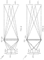
- the projection unit 112 receives pre-distorted images that are separately generated by each of the image generators 114, and then projects the pre-distorted images the windscreen 104. It will be appreciated that the projection unit 112 may be variously implemented. Two exemplary implementations are depicted in FIGS. 2 and 3 , and with reference thereto will now be briefly described. Before doing so, it is noted that the depicted examples are both unfolded, and do not include any folding by the windscreen 104 or any other folding or correcting optics, such as a collimator.
- this projection unit 112 includes a right illuminator 202-R, a left illuminator 202-L, a lens 204, and an active matrix liquid crystal display (AMLCD) 206.
- the AMLCD 206 is configured to operate in field sequential mode, and is coupled to alternately receive and display pre-distorted right-eye and left-eye images, respectively, that are generated by the image generators 114.
- the right-eye and left-eye illuminators 202-R, 202-L serve to backlight the AMLCD 206, and have their timing synchronized such that the right-eye illuminator 202-R illuminates the pre-distorted right-eye image, and the left-eye illuminator 202-L illuminates the pre-distorted left-eye image.
- the right and left illuminators 202-R, 202-L could be implemented as a single, relatively larger illuminator with an electronically modifiable light valve, such as an LCD, to define and appropriately synchronize the effective output apertures.
- the lens 204 which may be a Fresnel lens or the like, is disposed between the right and left illuminators 202-R, 202-L and the AMLCD 206.
- the lens 204 is configured to re-image each of the right and left illuminators 202-R, 202-L to the corresponding right eyebox 108-R and left eyebox 108-L, respectively.
- the output of each illuminator is reimaged with magnification, though other configurations are certainly possible.
- the projection unit 112 additionally includes a motion mechanism 208.
- the depicted motion mechanism 208 is coupled to, and is configured to selectively move, the right and left illuminators 202-R, 202-L.
- the motion mechanism 208 could instead be coupled to and configured to selectively move the lens 204.
- Only one axis of motion is depicted, this should not be construed as limiting in any way, and other axes of translational or rotational motion may be implemented. The purpose for including the motion mechanism 208 will be described further below.
- This example includes right 302-R and left 302-L image projectors, which receive the corresponding pre-distorted right-eye and left-eye images, and a lens 304, such as a Fresnel lens.
- the depicted example includes a high gain diffuser 306.
- the high gain diffuser 306 is configured in this example to function as a rear projection screen upon which the projectors are focused.
- the gain profile of diffuser 306 is selected to spread the viewing angle and thereby expand the right and the left eyeboxes 108-R, 108-L, while preventing (or at least minimizing) crosstalk between the right and the left eyeboxes 108-R, 108-L.
- an asymmetric gain profile may be selected to spread enlarge the eyebox further in one direction, such as the vertical direction, than in the other.
- motion mechanism 208 may also be optionally included to move either the projectors or the Fresnel lens.
- the image generators 114 generate and individually correct the images associated with each eye of a viewer, such as a pilot. That is, the right-eye image generator 114-R generates pre-distorted images associated with the right eye of a viewer, and the left-eye image generator 114-L generates pre-distorted images associated with the left eye of a viewer.
- the image generators 114 individually pre-distort the generated images so that the perceived binocular image of each displayed feature is located, after reflection by the windscreen 104, at the desired target position for that feature.
- the desired target position has a binocular vergence corresponding to optical infinity or far distance.
- the image generators 112 may be capable of moving the target position closer, adjusting the effective vergence distance for viewing the feature by appropriately shifting the display feature in either or both of the right-eye and left-eye images.
- FIG. 4 depicts a single rectilinear grid 402 having perpendicular row and column lines and square corners.
- this single rectilinear grid 402 is the image being supplied from the image data source 114 and projected by the projection unit 112 toward the windscreen 104. It is additionally assumed that this image is not yet pre-distorted.
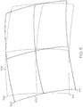
- the corresponding exemplary images reflected by the windscreen 104 to the right and the left eyeboxes 108-R, 108-L are depicted in FIG. 5 , and illustrate how the windscreen 104 may distort the reflected images.
- distorted image 502 depicts how the rectilinear grid 402 may appear at the right eyebox 108-R
- distorted image 504 depicts how the rectilinear grid 402 may appear at the left eyebox 108-L.
- the two images 502, 504 will not coincide, and several misleading visual cues may result which are strongly dependent upon the particular windscreen shape and viewing configuration.
- the depicted system 100 is particularly directed at minimizing vergence cues that are misleading or even uncomfortable to view.
- the depicted system 100 compensates that lateral separation in the presence of the image-distorting windscreen based on the specific viewing pupil locations to eliminate spurious and potentially dramatic apparent distance errors.
- dipvergence is a vertical disparity between the views seen by the right and left eyes.
- Such vertical disparity is very uncomfortable to view, and is clearly present in the differentially distorted binocular views depicted in FIG. 5 .
- the example depicted in FIG. 5 additionally illustrates how both the dipvergence and the convergence can vary dramatically across the effective field of view.
- the apparent upper left corner 506 seen by the left eye is both above and to the right of the corresponding corner 508 as seen by the right eye, while the geometrical relationship is quite different for the apparent lower left corners 512, 514 and the other corners as well.
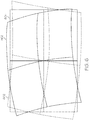
- FIGS. 6 and 7 depicts the pre-distorted right-eye image 602, the distorted image 502, and the resulting nominal image 604 that would be seen from the right eyebox 108-R
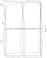
- FIG. 7 depicts the pre-distorted left-eye image 702, the distorted image 504, and the resulting nominal image 704 that would be seen from the left eyebox 108-L.
- the resulting nominal images 604, 704 are non-distorted and correspond to the rectilinear grid 402.
- the convergence is further adjusted to zero (e.g., parallel rays) by adjusting the effective lateral separation of the distortion-compensated nominal images 602 and 702 to match the inter-pupillary distance (IPD) of the viewer.
- IPD inter-pupillary distance
- the location of a feature may also be adjusted to be conformal with a feature or object that is not part of the image being displayed but can be seen within the field of view, such as through the windscreen 104 or in front of the windscreen 104.
- the windscreen 104 which functions as a combiner, is a conventional windscreen that is installed in a vehicle, such as various types of aircraft.
- the windscreen 104 has not been specifically designed with optimal optical characteristics, although such optimization is optional and can improve overall performance.
- the optical characteristics of the windscreen 104 have been measured, and these characteristics are preferably stored in each of the image generators 114. In this way, the right-eye image 106-R and the left-eye image 106-L are generated based not only on the image content, but on the optical characteristics of the windscreen 104 and any optional collimation or correction optics that may be present.
- the windscreen 104 may not be symmetric, with respect to the locations of the eyeboxes 108, in the region receiving the right and left eye images 106-R, 106-L. Indeed, in some embodiments, the symmetry axis relating the right eyebox 106-R to the left eyebox 106-L does not match any symmetry axis of the windscreen (if such symmetry axis even exists).
- the image generators 114 are configured to compensate the images for slight deformations of the windscreen 104.
- the system 100 includes one or more windscreen sensors 118 (e.g., 118-1, 118-2, 118-3 ... 118-N).
- Each windscreen sensor 118 is configured to sense one or more parameters representative of the optical characteristics of the windscreen 104, and supply parameter signals representative thereof to the projector 102.
- the number of windscreen sensors 118 may vary.
- each sensor may be variously configured and implemented to sense various parameters of the windscreen 104 that may impact its optical characteristics.
- the windscreen sensors 118 may sense windscreen deformation, shifting, or temperature, just to name a few.
- windscreen sensors 118 may be disposed in contact with, or remote from, the windscreen 104.
- a light source may be directed toward the windscreen 104, and the reflected light may be monitored by a sensor to detect deformation of the windscreen 104.
- the projector 102 and more specifically each image generator 114, is further configured, in response to the parameter signals, to determine the optical characteristics of the windscreen 104.
- the image generators 114 based on the determined optical characteristics, compensate the generated right-eye and left-eye images 106-R, 106-L for any variations in the optical characteristics of the windscreen 104.
- the system 100 includes an avionics data source 122.
- the avionics data source 122 which may be implemented using individual sensors, individual systems or subsystems, or as a single system, is configured to supply avionics data representative of one or more avionics parameters.
- the avionics parameters may vary, but are parameters that impact the optical characteristics of the windscreen 104. Some non-limiting examples of such avionics parameters include altitude, airspeed, and differential pressure, just to name a few.
- the projector 102 is further configured, in response to the avionics data, to determine the optical characteristics of the windscreen 104.
- the image generators 114 based on the determined optical characteristics, compensate the generated right-eye and left-eye images 106-R, 106-L for any variations in the optical characteristics of the windscreen 104.
- the system 100 may be configured such that the eyeboxes 108 are stationary or dynamic. As may be appreciated, when the eyeboxes 108 are not movable, the range of useful head motion from which the display could be seen is limited. When the eyeboxes 108 remain fixed in their locations, the image content that is displayed is dynamically adjusted based on the location of each eye within the eyeboxes. In this case, the location of each eye, and more specifically the location of the pupil of each eye, is determined, and image compensation, such as image warping or distortion correction (pre-distorting), is actively applied for each frame of each image 106-R, 106-L, based on the determined pupil location.
- image compensation such as image warping or distortion correction (pre-distorting
- the locations of the eyeboxes 108 themselves are dynamically repositioned to follow the locations of the respective eyes.
- both the image pre-distortion and the locations of the right eyebox 108-R and the left eyebox 108-L can vary with the locations of the right eye and left eye, respectively, of the viewer.
- the system includes a pupil location tracker 124.
- the pupil location tracker 124 is configured to sense the locations of the right eye and the left eye of a viewer, and to supply eye location signals representative of each eye location to the projector 102. It should be noted that the pupil location tracker 124 is not necessarily configured to sense and determine the direction in which the viewer may be looking. Rather, it is configured to sense the three-dimensional location of the right and left eyes of the viewer.
- the pupil location tracker 124 may be implemented using any one of numerous known head and/or eye tracking schemes.
- a dual camera system is used.
- each camera and associated image analysis algorithm detects the location of each eye pupil in the respective camera image. The true spatial position of each eye is then determined via triangulation or similar analysis of the image pair.
- the means for dynamically repositioning the eyeboxes 108 may vary.
- the system 100 may include the motion mechanism 208 depicted in FIGS. 2 and 3 and briefly described above to move, for example, the right and left illuminators 202-R, 202-L, or to move the lens 204.
- the system 100 may instead include a scanning mirror system, or an electronically addressable illumination source or aperture within the projection unit 112 to vary eyebox positions, just to name a few. It should be noted that with each of these dynamic examples, the system 100 may also be configured to determine if one of the eyes of a viewer has moved beyond its respective eyebox range and into the opposite eyebox range. For example, if the right eye of the viewer moves into the left eyebox 108-L and the left eye of the view is outside of the left eyebox 108-L, the pupil location tracker 124 can provide the location of the viewer's right pupil to the image data source 114, so that the viewer's right eye can view the suitably corrected image for its particular location.
- This system and method described herein is implemented using relatively simple HUD optics while actively maintaining minimal vergence errors, especially minimal dipvergence errors, as well as high conformality if desired.
- active compensation the optical requirements for each projected eyebox are greatly simplified, which allows the use of compact and low cost optics.
- the required degree of image collimation by any optional additional optics may be significantly reduced or potentially eliminated.
- Skilled artisans may implement the described functionality in varying ways for each particular application, but such implementation decisions should not be interpreted as causing a departure from the scope of the present invention.
- an embodiment of a system or a component may employ various integrated circuit components, e.g., memory elements, digital signal processing elements, logic elements, look-up tables, or the like, which may carry out a variety of functions under the control of one or more microprocessors or other control devices.
- integrated circuit components e.g., memory elements, digital signal processing elements, logic elements, look-up tables, or the like, which may carry out a variety of functions under the control of one or more microprocessors or other control devices.
- DSP digital signal processor
- ASIC application specific integrated circuit
- FPGA field programmable gate array
- a general-purpose processor may be a microprocessor, but in the alternative, the processor may be any conventional processor, controller, microcontroller, or state machine.
- a processor may also be implemented as a combination of computing devices, e.g., a combination of a DSP and a microprocessor, a plurality of microprocessors, one or more microprocessors in conjunction with a DSP core, or any other such configuration.
- a software module may reside in RAM memory, flash memory, ROM memory, EPROM memory, EEPROM memory, registers, hard disk, a removable disk, a CD-ROM, or any other form of storage medium known in the art.
- An exemplary storage medium is coupled to the processor such that the processor can read information from, and write information to, the storage medium.
- the storage medium may be integral to the processor.
- the processor and the storage medium may reside in an ASIC.
- the ASIC may reside in a user terminal.
- the processor and the storage medium may reside as discrete components in a user terminal
Landscapes
- Physics & Mathematics (AREA)
- General Physics & Mathematics (AREA)
- Optics & Photonics (AREA)
- Controls And Circuits For Display Device (AREA)
- Instrument Panels (AREA)
Claims (7)
- Konformes Head-up-Display-System, das umfasst:einen Projektor (102), der dazu konfiguriert ist, individuell und separat ein vorverzerrtes Bild für das rechte Auge (106-R) und ein vorverzerrtes Bild für das linke Auge (106-L) zu erzeugen und zu projizieren;einen Kombinierer (104), der derart positioniert ist, dass er das vorverzerrte Bild für das rechte Auge und das vorverzerrte Bild für das linke Auge empfängt und (i) das vorverzerrte Bild für das rechte Auge reflektiert, um ein reflektiertes Bild für das rechte Auge zu einer rechten Eye-Box (108-R) zu liefern, und (ii) das vorverzerrte Bild für das linke Auge reflektiert, um ein reflektiertes Bild für das linke Auge zu einer linken Eye-Box (108-L) zu liefern; gekennzeichnet durcheine Avionik-Datenquelle, die dazu konfiguriert ist, Avionik-Daten, die für einen oder mehrere Avionik-Parameter repräsentativ sind, zu dem Projektor zu liefern,wobei:das reflektierte Bild für das rechte Auge und das reflektierte Bild für das linke Auge jeweils unverzerrte Bilder sind,das reflektierte Bild für das rechte Auge und das reflektierte Bild für das linke Auge ein binokulares Bild darstellen, das im Wesentlichen keine Divergenz aufweist,der Kombinierer eine Fahrzeugwindschutzscheibe ist; undder Projektor ferner dazu konfiguriert ist, das vorverzerrte Bild für das rechte Auge und das vorverzerrte Bild für das linke Auge basierend auf einem oder mehreren optischen Merkmalen der Windschutzscheibe zu erzeugen, undder Projektor ferner als Reaktion auf die Avionikdaten konfiguriert ist, um das eine oder die mehreren optischen Merkmale der Windschutzscheibe zu bestimmen.
- System nach Anspruch 1, das ferner umfasst:einen oder mehrere Windschutzscheibensensoren, wobei jeder Windschutzscheibensensor dazu konfiguriert ist, einen oder mehrere Parameter, die für die optischen Merkmale der Windschutzscheibe repräsentativ sind, abzutasten und repräsentative Parametersignale davon zu dem Projektor zu liefern,wobei der Projektor ferner als Reaktion auf die Parametersignale dazu konfiguriert ist, das eine oder die mehreren optischen Merkmale der Windschutzscheibe zu bestimmen.
- System nach Anspruch 1, das ferner umfasst:einen Pupillenlage-Tracker, der dazu konfiguriert ist, Lagen eines rechten Auges und eines linken Auges eines Betrachters abzutasten, wobei der Pupillen-Tracker ferner dazu konfiguriert ist, Augenlagesignale, die für jede Augenlage repräsentativ sind, zu dem Projektor zu liefern,wobei der Projektor auf die Lagesignale anspricht, um selektiv und individuell jedes Einzelbild des Bildes für das rechte Auge und des Bildes für das linke Auge zu kompensieren, um in Bezug auf die Lagen des rechten Auges bzw. des linken Auges des Betrachters zu variieren.
- System nach Anspruch 3,
wobei der Projektor auf die Lagesignale anspricht, um die Lagen der rechten Eye-Box und der linken Eye-Box selektiv und individuell zu kompensieren, um in Bezug auf die Lagen des rechten Auges bzw. des linken Auges des Betrachters zu variieren. - System nach Anspruch 1, wobei der Kombinierer in Bezug auf Lagen der rechten und linken Eye-Box in einem Bereich, der die Bilder für das rechte und das linke Auge empfängt, asymmetrisch ist.
- System nach Anspruch 5, wobei:
eine erste Symmetrieachse die rechte Eye-Box 106-R mit der linken Eye-Box 106-L verbindet; und die erste Symmetrieachse mit keiner Symmetrieachse der Windschutzscheibe übereinstimmt. - Verfahren zum Anzeigen eines konformen Head-up-Display-Bildes, das die Schritte umfasst des:individuellen und getrennten Erzeugens und Projizierens eines vorverzerrten Bildes für das rechte Auge (106-R) und eines vorverzerrten Bildes für das linke Auge (106-L) zu einer Windschutzscheibe (104);Reflektierens des vorverzerrten Bildes für das rechte Auge von der Windschutzscheibe, um ein reflektiertes Bild für das rechte Auge zu einer rechten Eye-Box (108-R) zu liefern; undReflektieren des vorverzerrten Bildes für das linke Auge von der Windschutzscheibe, um ein reflektiertes Bild für das linke Auge zu einer linke EyeBox (108-L) zu liefern,wobei:das reflektierte Bild für das rechte Auge und das reflektierte Bild für das linke Auge jeweils unverzerrte Bilder sind,das reflektierte Bild für das rechte Auge und das reflektierte Bild für das linke Auge ein binokulares Bild darstellen, das im Wesentlichen null Divergenz aufweist, unddas vorverzerrte Bild für das rechte Auge und das vorverzerrte Bild für das linke Auge basierend auf einem oder mehreren optischen Merkmalen der Windschutzscheibe erzeugt werden,dadurch gekennzeichnet, dass der Erzeugungsschritt das Bestimmen des einen oder der mehreren optischen Merkmale der Windschutzscheibe unter Verwenden von Avionikdaten, die für einen oder mehrere Avionikparameter repräsentativ sind, beinhaltet.
Applications Claiming Priority (1)
| Application Number | Priority Date | Filing Date | Title |
|---|---|---|---|
| US14/102,950 US9229228B2 (en) | 2013-12-11 | 2013-12-11 | Conformal capable head-up display |
Publications (2)
| Publication Number | Publication Date |
|---|---|
| EP2884329A1 EP2884329A1 (de) | 2015-06-17 |
| EP2884329B1 true EP2884329B1 (de) | 2021-08-25 |
Family
ID=51897209
Family Applications (1)
| Application Number | Title | Priority Date | Filing Date |
|---|---|---|---|
| EP14193519.7A Active EP2884329B1 (de) | 2013-12-11 | 2014-11-17 | Konformes leistungsfähiges Head-up-Display |
Country Status (3)
| Country | Link |
|---|---|
| US (1) | US9229228B2 (de) |
| EP (1) | EP2884329B1 (de) |
| CN (1) | CN104714301B (de) |
Families Citing this family (17)
| Publication number | Priority date | Publication date | Assignee | Title |
|---|---|---|---|---|
| US9606355B2 (en) | 2014-09-29 | 2017-03-28 | Honeywell International Inc. | Apparatus and method for suppressing double images on a combiner head-up display |
| TWI609199B (zh) * | 2016-06-30 | 2017-12-21 | 葉天守 | 反射式虛像顯示裝置 |
| US10261328B2 (en) * | 2016-09-02 | 2019-04-16 | Microsoft Technology Licensing, Llc | Enhanced illumination system |
| GB2559607B (en) * | 2017-02-13 | 2021-06-02 | Jaguar Land Rover Ltd | Apparatus and method for controlling a vehicle display |
| GB201713051D0 (en) | 2017-08-15 | 2017-09-27 | Imagination Tech Ltd | Low latency distortion unit for head mounted displays |
| EP3807705B1 (de) * | 2018-06-15 | 2025-08-06 | Continental Automotive Technologies GmbH | Head-up-display für ein fahrzeug |
| WO2020048461A1 (zh) * | 2018-09-03 | 2020-03-12 | 广东虚拟现实科技有限公司 | 三维立体显示方法、终端设备及存储介质 |
| CN111948808B (zh) * | 2019-05-17 | 2025-11-18 | 未来(北京)黑科技有限公司 | 一种抬头显示器 |
| JP7221161B2 (ja) * | 2019-07-10 | 2023-02-13 | マクセル株式会社 | ヘッドアップディスプレイ及びそのキャリブレーション方法 |
| JP2021056369A (ja) * | 2019-09-30 | 2021-04-08 | セイコーエプソン株式会社 | ヘッドマウントディスプレイ |
| JP7276062B2 (ja) * | 2019-10-09 | 2023-05-18 | 株式会社デンソー | 虚像表示装置及び表示制御装置 |
| CN114730089A (zh) * | 2019-12-20 | 2022-07-08 | 日本精机株式会社 | 平视显示器 |
| CN113156643B (zh) * | 2020-01-22 | 2023-08-15 | 未来(北京)黑科技有限公司 | 基于立体视觉显示的车辆显示系统 |
| CN113824947A (zh) * | 2020-06-18 | 2021-12-21 | 观致汽车有限公司 | 投影式裸眼3d显示设备、方法、电子设备及存储介质 |
| JP7374273B2 (ja) * | 2020-09-09 | 2023-11-06 | マクセル株式会社 | 情報表示装置 |
| CN112731664A (zh) * | 2020-12-28 | 2021-04-30 | 北京经纬恒润科技股份有限公司 | 一种车载增强现实抬头显示系统及显示方法 |
| JP7799430B2 (ja) * | 2021-10-25 | 2026-01-15 | キヤノン株式会社 | 画像処理装置、制御方法及びプログラム |
Citations (4)
| Publication number | Priority date | Publication date | Assignee | Title |
|---|---|---|---|---|
| US5731902A (en) * | 1996-08-19 | 1998-03-24 | Delco Electronics Corporation | Head-up display combiner binocular test fixture |
| WO2007084267A2 (en) * | 2006-01-18 | 2007-07-26 | Eastman Kodak Company | A method for rectifying stereoscopic display systems |
| US20090005961A1 (en) * | 2004-06-03 | 2009-01-01 | Making Virtual Solid, L.L.C. | En-Route Navigation Display Method and Apparatus Using Head-Up Display |
| DE102009043351A1 (de) * | 2009-09-29 | 2011-04-07 | Bayerische Motoren Werke Aktiengesellschaft | Verfahren zum Erzeugen eines Stereobilds durch eine Projektionseinheit für ein Head-Up-Display und Projektionseinheit für ein Head-Up-Display |
Family Cites Families (22)
| Publication number | Priority date | Publication date | Assignee | Title |
|---|---|---|---|---|
| US4723160A (en) * | 1984-08-01 | 1988-02-02 | Grumman Aerospace Corporation | Windscreen deviation correcting pilot display |
| US4632508A (en) | 1984-08-01 | 1986-12-30 | Grumman Aerospace Corporation | Windscreen deviation correcting pilot display |
| DE3822222A1 (de) | 1988-07-01 | 1990-01-04 | Bosch Gmbh Robert | Einrichtung fuer head-up-displays an kraftfahrzeugen |
| US5805119A (en) * | 1992-10-13 | 1998-09-08 | General Motors Corporation | Vehicle projected display using deformable mirror device |
| KR20000062255A (ko) * | 1996-12-20 | 2000-10-25 | 칼 하인쯔 호르닝어 | 1인 이상용 정보 디스플레이 시스템 |
| US6473240B1 (en) * | 2000-09-19 | 2002-10-29 | Rockwell Collins | Apparatus and method for using orthogonally polarized light in projection cockpit displays |
| JP4677104B2 (ja) | 2001-01-10 | 2011-04-27 | 矢崎総業株式会社 | 車両用表示装置 |
| US7203005B2 (en) | 2002-05-22 | 2007-04-10 | Chelix Technologies, Inc. | Real image configuration for a high efficiency heads-up display (HUD) using a polarizing mirror and a polarization preserving screen |
| DE10224016A1 (de) | 2002-05-29 | 2003-12-18 | Siemens Ag | Anzeigevorrichtung |
| US6952312B2 (en) | 2002-12-31 | 2005-10-04 | 3M Innovative Properties Company | Head-up display with polarized light source and wide-angle p-polarization reflective polarizer |
| DE20304399U1 (de) | 2003-03-18 | 2003-06-05 | Horizont Deutschland Gmbh | Projektionsvorrichtung |
| FR2860601B1 (fr) | 2003-10-07 | 2005-12-30 | Thales Sa | Procede de correction de distorsion d'un imageur a cristaux liquides |
| DE202005021565U1 (de) | 2005-05-30 | 2008-10-16 | Toshiba Electronics Europe Gmbh | Integrierte Schaltung mit Warping-Berechnungseinheit |
| US8491121B2 (en) * | 2007-10-09 | 2013-07-23 | Elbit Systems Of America, Llc | Pupil scan apparatus |
| US8422112B2 (en) | 2008-02-04 | 2013-04-16 | Industrial Technology Research Institute | Display system |
| JP5075776B2 (ja) * | 2008-09-22 | 2012-11-21 | 株式会社東芝 | 表示装置及び移動体 |
| JP5341462B2 (ja) | 2008-10-14 | 2013-11-13 | キヤノン株式会社 | 収差補正方法、画像処理装置および画像処理システム |
| EP2465004A2 (de) | 2009-08-13 | 2012-06-20 | BAE Systems PLC | Blickfeld-anzeigesystem |
| DE102009054232A1 (de) | 2009-11-21 | 2011-05-26 | Bayerische Motoren Werke Aktiengesellschaft | Head-up-Display |
| US20120127381A1 (en) * | 2010-11-23 | 2012-05-24 | Matvey Lvovskiy | Wide-angle head-up display |
| CN202141854U (zh) * | 2011-06-24 | 2012-02-08 | 南京英田光学工程有限公司 | 远距离特大出瞳直径透镜式检测仪光学系统 |
| US9347792B2 (en) * | 2011-10-31 | 2016-05-24 | Honeywell International Inc. | Systems and methods for displaying images with multi-resolution integration |
-
2013
- 2013-12-11 US US14/102,950 patent/US9229228B2/en active Active
-
2014
- 2014-11-17 EP EP14193519.7A patent/EP2884329B1/de active Active
- 2014-12-10 CN CN201410749787.1A patent/CN104714301B/zh not_active Expired - Fee Related
Patent Citations (4)
| Publication number | Priority date | Publication date | Assignee | Title |
|---|---|---|---|---|
| US5731902A (en) * | 1996-08-19 | 1998-03-24 | Delco Electronics Corporation | Head-up display combiner binocular test fixture |
| US20090005961A1 (en) * | 2004-06-03 | 2009-01-01 | Making Virtual Solid, L.L.C. | En-Route Navigation Display Method and Apparatus Using Head-Up Display |
| WO2007084267A2 (en) * | 2006-01-18 | 2007-07-26 | Eastman Kodak Company | A method for rectifying stereoscopic display systems |
| DE102009043351A1 (de) * | 2009-09-29 | 2011-04-07 | Bayerische Motoren Werke Aktiengesellschaft | Verfahren zum Erzeugen eines Stereobilds durch eine Projektionseinheit für ein Head-Up-Display und Projektionseinheit für ein Head-Up-Display |
Also Published As
| Publication number | Publication date |
|---|---|
| CN104714301A (zh) | 2015-06-17 |
| EP2884329A1 (de) | 2015-06-17 |
| US9229228B2 (en) | 2016-01-05 |
| CN104714301B (zh) | 2019-07-09 |
| US20150160457A1 (en) | 2015-06-11 |
Similar Documents
| Publication | Publication Date | Title |
|---|---|---|
| US9229228B2 (en) | Conformal capable head-up display | |
| US10459224B2 (en) | High transmittance eyewear for head-up displays | |
| US10915148B1 (en) | Dynamic distortion correction for optical compensation | |
| US11297304B2 (en) | Virtual image display device and head mounted display using same | |
| US10317680B1 (en) | Optical aberration correction based on user eye position in head mounted displays | |
| CN104253990B (zh) | 用车辆视野显示装置的成像器显示三维图像的方法和设备 | |
| US8708498B2 (en) | Display apparatus for vehicle and display method | |
| EP2436182B1 (de) | Multiprojektorsystem, multiprojektorverfahren und dazugehöriges programm | |
| JP2014225017A (ja) | 車両の乗員の視野に画像情報を投影するための装置及び方法 | |
| EP3961353B1 (de) | Verfahren und vorrichtung zur steuerung einer head-up-anzeige auf basis des augenverfolgungsstatus | |
| CN105988220A (zh) | 用于运行车辆用的自动立体观测的视野显示器的方法和控制设备 | |
| KR20240042166A (ko) | 제어 시스템 및 렌더링 파이프라인 | |
| US12242129B2 (en) | Device and method to calibrate parallax optical element for temperature change | |
| JPS6146925A (ja) | 風防ガラスの偏差補正用パイロツト表示装置及び表示方法 | |
| US9684166B2 (en) | Motor vehicle and display of a three-dimensional graphical object | |
| WO2026065935A1 (zh) | 图像显示方法及相关设备 | |
| US10698218B1 (en) | Display system with oscillating element | |
| US12366747B2 (en) | Head-up display device and control method thereof | |
| US11758119B2 (en) | Low cost HUD using stereo and head tracking | |
| JP7424823B2 (ja) | 画像表示装置 | |
| WO2019012739A1 (ja) | 虚像表示装置 | |
| US20230258932A1 (en) | Head-up display device and control method thereof | |
| US12366751B2 (en) | Apparatus for projecting images towards a user | |
| CN120610406A (zh) | 包括有反射和透射表面的棱镜和副镜的用于多个观看者的多路复用虚拟显示系统 |
Legal Events
| Date | Code | Title | Description |
|---|---|---|---|
| PUAI | Public reference made under article 153(3) epc to a published international application that has entered the european phase |
Free format text: ORIGINAL CODE: 0009012 |
|
| 17P | Request for examination filed |
Effective date: 20141117 |
|
| AK | Designated contracting states |
Kind code of ref document: A1 Designated state(s): AL AT BE BG CH CY CZ DE DK EE ES FI FR GB GR HR HU IE IS IT LI LT LU LV MC MK MT NL NO PL PT RO RS SE SI SK SM TR |
|
| AX | Request for extension of the european patent |
Extension state: BA ME |
|
| RIN1 | Information on inventor provided before grant (corrected) |
Inventor name: LARSON, BRENT D. Inventor name: LU, KANGHUA |
|
| RAP1 | Party data changed (applicant data changed or rights of an application transferred) |
Owner name: HONEYWELL INTERNATIONAL INC. |
|
| STAA | Information on the status of an ep patent application or granted ep patent |
Free format text: STATUS: EXAMINATION IS IN PROGRESS |
|
| 17Q | First examination report despatched |
Effective date: 20181106 |
|
| GRAP | Despatch of communication of intention to grant a patent |
Free format text: ORIGINAL CODE: EPIDOSNIGR1 |
|
| STAA | Information on the status of an ep patent application or granted ep patent |
Free format text: STATUS: GRANT OF PATENT IS INTENDED |
|
| GRAS | Grant fee paid |
Free format text: ORIGINAL CODE: EPIDOSNIGR3 |
|
| INTG | Intention to grant announced |
Effective date: 20210622 |
|
| GRAA | (expected) grant |
Free format text: ORIGINAL CODE: 0009210 |
|
| STAA | Information on the status of an ep patent application or granted ep patent |
Free format text: STATUS: THE PATENT HAS BEEN GRANTED |
|
| AK | Designated contracting states |
Kind code of ref document: B1 Designated state(s): AL AT BE BG CH CY CZ DE DK EE ES FI FR GB GR HR HU IE IS IT LI LT LU LV MC MK MT NL NO PL PT RO RS SE SI SK SM TR |
|
| REG | Reference to a national code |
Ref country code: GB Ref legal event code: FG4D |
|
| REG | Reference to a national code |
Ref country code: CH Ref legal event code: EP |
|
| REG | Reference to a national code |
Ref country code: IE Ref legal event code: FG4D Ref country code: AT Ref legal event code: REF Ref document number: 1424399 Country of ref document: AT Kind code of ref document: T Effective date: 20210915 |
|
| REG | Reference to a national code |
Ref country code: DE Ref legal event code: R096 Ref document number: 602014079639 Country of ref document: DE |
|
| REG | Reference to a national code |
Ref country code: LT Ref legal event code: MG9D |
|
| REG | Reference to a national code |
Ref country code: NL Ref legal event code: MP Effective date: 20210825 |
|
| REG | Reference to a national code |
Ref country code: AT Ref legal event code: MK05 Ref document number: 1424399 Country of ref document: AT Kind code of ref document: T Effective date: 20210825 |
|
| PG25 | Lapsed in a contracting state [announced via postgrant information from national office to epo] |
Ref country code: LT Free format text: LAPSE BECAUSE OF FAILURE TO SUBMIT A TRANSLATION OF THE DESCRIPTION OR TO PAY THE FEE WITHIN THE PRESCRIBED TIME-LIMIT Effective date: 20210825 Ref country code: BG Free format text: LAPSE BECAUSE OF FAILURE TO SUBMIT A TRANSLATION OF THE DESCRIPTION OR TO PAY THE FEE WITHIN THE PRESCRIBED TIME-LIMIT Effective date: 20211125 Ref country code: AT Free format text: LAPSE BECAUSE OF FAILURE TO SUBMIT A TRANSLATION OF THE DESCRIPTION OR TO PAY THE FEE WITHIN THE PRESCRIBED TIME-LIMIT Effective date: 20210825 Ref country code: NO Free format text: LAPSE BECAUSE OF FAILURE TO SUBMIT A TRANSLATION OF THE DESCRIPTION OR TO PAY THE FEE WITHIN THE PRESCRIBED TIME-LIMIT Effective date: 20211125 Ref country code: PT Free format text: LAPSE BECAUSE OF FAILURE TO SUBMIT A TRANSLATION OF THE DESCRIPTION OR TO PAY THE FEE WITHIN THE PRESCRIBED TIME-LIMIT Effective date: 20211227 Ref country code: ES Free format text: LAPSE BECAUSE OF FAILURE TO SUBMIT A TRANSLATION OF THE DESCRIPTION OR TO PAY THE FEE WITHIN THE PRESCRIBED TIME-LIMIT Effective date: 20210825 Ref country code: FI Free format text: LAPSE BECAUSE OF FAILURE TO SUBMIT A TRANSLATION OF THE DESCRIPTION OR TO PAY THE FEE WITHIN THE PRESCRIBED TIME-LIMIT Effective date: 20210825 Ref country code: RS Free format text: LAPSE BECAUSE OF FAILURE TO SUBMIT A TRANSLATION OF THE DESCRIPTION OR TO PAY THE FEE WITHIN THE PRESCRIBED TIME-LIMIT Effective date: 20210825 Ref country code: SE Free format text: LAPSE BECAUSE OF FAILURE TO SUBMIT A TRANSLATION OF THE DESCRIPTION OR TO PAY THE FEE WITHIN THE PRESCRIBED TIME-LIMIT Effective date: 20210825 Ref country code: HR Free format text: LAPSE BECAUSE OF FAILURE TO SUBMIT A TRANSLATION OF THE DESCRIPTION OR TO PAY THE FEE WITHIN THE PRESCRIBED TIME-LIMIT Effective date: 20210825 |
|
| PG25 | Lapsed in a contracting state [announced via postgrant information from national office to epo] |
Ref country code: PL Free format text: LAPSE BECAUSE OF FAILURE TO SUBMIT A TRANSLATION OF THE DESCRIPTION OR TO PAY THE FEE WITHIN THE PRESCRIBED TIME-LIMIT Effective date: 20210825 Ref country code: LV Free format text: LAPSE BECAUSE OF FAILURE TO SUBMIT A TRANSLATION OF THE DESCRIPTION OR TO PAY THE FEE WITHIN THE PRESCRIBED TIME-LIMIT Effective date: 20210825 Ref country code: GR Free format text: LAPSE BECAUSE OF FAILURE TO SUBMIT A TRANSLATION OF THE DESCRIPTION OR TO PAY THE FEE WITHIN THE PRESCRIBED TIME-LIMIT Effective date: 20211126 |
|
| PG25 | Lapsed in a contracting state [announced via postgrant information from national office to epo] |
Ref country code: NL Free format text: LAPSE BECAUSE OF FAILURE TO SUBMIT A TRANSLATION OF THE DESCRIPTION OR TO PAY THE FEE WITHIN THE PRESCRIBED TIME-LIMIT Effective date: 20210825 |
|
| PG25 | Lapsed in a contracting state [announced via postgrant information from national office to epo] |
Ref country code: DK Free format text: LAPSE BECAUSE OF FAILURE TO SUBMIT A TRANSLATION OF THE DESCRIPTION OR TO PAY THE FEE WITHIN THE PRESCRIBED TIME-LIMIT Effective date: 20210825 |
|
| REG | Reference to a national code |
Ref country code: DE Ref legal event code: R097 Ref document number: 602014079639 Country of ref document: DE |
|
| PG25 | Lapsed in a contracting state [announced via postgrant information from national office to epo] |
Ref country code: SM Free format text: LAPSE BECAUSE OF FAILURE TO SUBMIT A TRANSLATION OF THE DESCRIPTION OR TO PAY THE FEE WITHIN THE PRESCRIBED TIME-LIMIT Effective date: 20210825 Ref country code: SK Free format text: LAPSE BECAUSE OF FAILURE TO SUBMIT A TRANSLATION OF THE DESCRIPTION OR TO PAY THE FEE WITHIN THE PRESCRIBED TIME-LIMIT Effective date: 20210825 Ref country code: RO Free format text: LAPSE BECAUSE OF FAILURE TO SUBMIT A TRANSLATION OF THE DESCRIPTION OR TO PAY THE FEE WITHIN THE PRESCRIBED TIME-LIMIT Effective date: 20210825 Ref country code: EE Free format text: LAPSE BECAUSE OF FAILURE TO SUBMIT A TRANSLATION OF THE DESCRIPTION OR TO PAY THE FEE WITHIN THE PRESCRIBED TIME-LIMIT Effective date: 20210825 Ref country code: CZ Free format text: LAPSE BECAUSE OF FAILURE TO SUBMIT A TRANSLATION OF THE DESCRIPTION OR TO PAY THE FEE WITHIN THE PRESCRIBED TIME-LIMIT Effective date: 20210825 Ref country code: AL Free format text: LAPSE BECAUSE OF FAILURE TO SUBMIT A TRANSLATION OF THE DESCRIPTION OR TO PAY THE FEE WITHIN THE PRESCRIBED TIME-LIMIT Effective date: 20210825 |
|
| PG25 | Lapsed in a contracting state [announced via postgrant information from national office to epo] |
Ref country code: MC Free format text: LAPSE BECAUSE OF FAILURE TO SUBMIT A TRANSLATION OF THE DESCRIPTION OR TO PAY THE FEE WITHIN THE PRESCRIBED TIME-LIMIT Effective date: 20210825 |
|
| REG | Reference to a national code |
Ref country code: CH Ref legal event code: PL |
|
| PLBE | No opposition filed within time limit |
Free format text: ORIGINAL CODE: 0009261 |
|
| STAA | Information on the status of an ep patent application or granted ep patent |
Free format text: STATUS: NO OPPOSITION FILED WITHIN TIME LIMIT |
|
| PG25 | Lapsed in a contracting state [announced via postgrant information from national office to epo] |
Ref country code: LU Free format text: LAPSE BECAUSE OF NON-PAYMENT OF DUE FEES Effective date: 20211117 Ref country code: IT Free format text: LAPSE BECAUSE OF FAILURE TO SUBMIT A TRANSLATION OF THE DESCRIPTION OR TO PAY THE FEE WITHIN THE PRESCRIBED TIME-LIMIT Effective date: 20210825 Ref country code: BE Free format text: LAPSE BECAUSE OF NON-PAYMENT OF DUE FEES Effective date: 20211130 |
|
| REG | Reference to a national code |
Ref country code: BE Ref legal event code: MM Effective date: 20211130 |
|
| 26N | No opposition filed |
Effective date: 20220527 |
|
| PG25 | Lapsed in a contracting state [announced via postgrant information from national office to epo] |
Ref country code: SI Free format text: LAPSE BECAUSE OF FAILURE TO SUBMIT A TRANSLATION OF THE DESCRIPTION OR TO PAY THE FEE WITHIN THE PRESCRIBED TIME-LIMIT Effective date: 20210825 Ref country code: LI Free format text: LAPSE BECAUSE OF NON-PAYMENT OF DUE FEES Effective date: 20211130 Ref country code: CH Free format text: LAPSE BECAUSE OF NON-PAYMENT OF DUE FEES Effective date: 20211130 |
|
| PG25 | Lapsed in a contracting state [announced via postgrant information from national office to epo] |
Ref country code: IE Free format text: LAPSE BECAUSE OF NON-PAYMENT OF DUE FEES Effective date: 20211117 |
|
| PG25 | Lapsed in a contracting state [announced via postgrant information from national office to epo] |
Ref country code: HU Free format text: LAPSE BECAUSE OF FAILURE TO SUBMIT A TRANSLATION OF THE DESCRIPTION OR TO PAY THE FEE WITHIN THE PRESCRIBED TIME-LIMIT; INVALID AB INITIO Effective date: 20141117 |
|
| PG25 | Lapsed in a contracting state [announced via postgrant information from national office to epo] |
Ref country code: CY Free format text: LAPSE BECAUSE OF FAILURE TO SUBMIT A TRANSLATION OF THE DESCRIPTION OR TO PAY THE FEE WITHIN THE PRESCRIBED TIME-LIMIT Effective date: 20210825 |
|
| P01 | Opt-out of the competence of the unified patent court (upc) registered |
Effective date: 20230525 |
|
| PGFP | Annual fee paid to national office [announced via postgrant information from national office to epo] |
Ref country code: GB Payment date: 20231121 Year of fee payment: 10 |
|
| PG25 | Lapsed in a contracting state [announced via postgrant information from national office to epo] |
Ref country code: MK Free format text: LAPSE BECAUSE OF FAILURE TO SUBMIT A TRANSLATION OF THE DESCRIPTION OR TO PAY THE FEE WITHIN THE PRESCRIBED TIME-LIMIT Effective date: 20210825 |
|
| PG25 | Lapsed in a contracting state [announced via postgrant information from national office to epo] |
Ref country code: TR Free format text: LAPSE BECAUSE OF FAILURE TO SUBMIT A TRANSLATION OF THE DESCRIPTION OR TO PAY THE FEE WITHIN THE PRESCRIBED TIME-LIMIT Effective date: 20210825 |
|
| PG25 | Lapsed in a contracting state [announced via postgrant information from national office to epo] |
Ref country code: MT Free format text: LAPSE BECAUSE OF FAILURE TO SUBMIT A TRANSLATION OF THE DESCRIPTION OR TO PAY THE FEE WITHIN THE PRESCRIBED TIME-LIMIT Effective date: 20210825 |
|
| GBPC | Gb: european patent ceased through non-payment of renewal fee |
Effective date: 20241117 |
|
| PG25 | Lapsed in a contracting state [announced via postgrant information from national office to epo] |
Ref country code: GB Free format text: LAPSE BECAUSE OF NON-PAYMENT OF DUE FEES Effective date: 20241117 |
|
| PGFP | Annual fee paid to national office [announced via postgrant information from national office to epo] |
Ref country code: DE Payment date: 20251126 Year of fee payment: 12 |
|
| PGFP | Annual fee paid to national office [announced via postgrant information from national office to epo] |
Ref country code: FR Payment date: 20251125 Year of fee payment: 12 |