EP2884060A1 - Device and method for operating volumetric expansion machines - Google Patents
Device and method for operating volumetric expansion machines Download PDFInfo
- Publication number
- EP2884060A1 EP2884060A1 EP13197480.0A EP13197480A EP2884060A1 EP 2884060 A1 EP2884060 A1 EP 2884060A1 EP 13197480 A EP13197480 A EP 13197480A EP 2884060 A1 EP2884060 A1 EP 2884060A1
- Authority
- EP
- European Patent Office
- Prior art keywords
- expansion machine
- abdampfraum
- working medium
- generator
- supply line
- Prior art date
- Legal status (The legal status is an assumption and is not a legal conclusion. Google has not performed a legal analysis and makes no representation as to the accuracy of the status listed.)
- Granted
Links
- 238000000034 method Methods 0.000 title claims abstract description 15
- 239000007788 liquid Substances 0.000 claims abstract description 46
- 239000012530 fluid Substances 0.000 claims description 37
- 238000001816 cooling Methods 0.000 claims description 32
- 230000001050 lubricating effect Effects 0.000 claims description 11
- 238000001704 evaporation Methods 0.000 claims description 10
- 238000005461 lubrication Methods 0.000 claims description 9
- 230000008020 evaporation Effects 0.000 claims description 8
- 230000001105 regulatory effect Effects 0.000 claims description 8
- 238000004804 winding Methods 0.000 claims description 8
- 238000004891 communication Methods 0.000 claims description 6
- 238000005086 pumping Methods 0.000 claims description 5
- 230000001276 controlling effect Effects 0.000 claims description 4
- 239000000314 lubricant Substances 0.000 description 15
- 238000011161 development Methods 0.000 description 11
- 230000018109 developmental process Effects 0.000 description 11
- 230000008901 benefit Effects 0.000 description 4
- 238000002347 injection Methods 0.000 description 4
- 239000007924 injection Substances 0.000 description 4
- 230000000694 effects Effects 0.000 description 3
- 238000010438 heat treatment Methods 0.000 description 3
- 238000013021 overheating Methods 0.000 description 3
- 238000009834 vaporization Methods 0.000 description 3
- 230000008016 vaporization Effects 0.000 description 3
- 238000004378 air conditioning Methods 0.000 description 2
- 230000006835 compression Effects 0.000 description 2
- 238000007906 compression Methods 0.000 description 2
- 238000005265 energy consumption Methods 0.000 description 2
- 239000000284 extract Substances 0.000 description 2
- 239000003507 refrigerant Substances 0.000 description 2
- 238000005057 refrigeration Methods 0.000 description 2
- 238000010079 rubber tapping Methods 0.000 description 2
- 206010063493 Premature ageing Diseases 0.000 description 1
- 208000032038 Premature aging Diseases 0.000 description 1
- 239000002826 coolant Substances 0.000 description 1
- 239000000110 cooling liquid Substances 0.000 description 1
- 239000005068 cooling lubricant Substances 0.000 description 1
- 230000007423 decrease Effects 0.000 description 1
- 230000001419 dependent effect Effects 0.000 description 1
- 238000009413 insulation Methods 0.000 description 1
- 239000000203 mixture Substances 0.000 description 1
- MSSNHSVIGIHOJA-UHFFFAOYSA-N pentafluoropropane Chemical compound FC(F)CC(F)(F)F MSSNHSVIGIHOJA-UHFFFAOYSA-N 0.000 description 1
- 238000011084 recovery Methods 0.000 description 1
- 238000005507 spraying Methods 0.000 description 1
- 230000007704 transition Effects 0.000 description 1
- 239000002918 waste heat Substances 0.000 description 1
Images

Classifications
-
- F—MECHANICAL ENGINEERING; LIGHTING; HEATING; WEAPONS; BLASTING
- F01—MACHINES OR ENGINES IN GENERAL; ENGINE PLANTS IN GENERAL; STEAM ENGINES
- F01D—NON-POSITIVE DISPLACEMENT MACHINES OR ENGINES, e.g. STEAM TURBINES
- F01D15/00—Adaptations of machines or engines for special use; Combinations of engines with devices driven thereby
- F01D15/10—Adaptations for driving, or combinations with, electric generators
-
- F—MECHANICAL ENGINEERING; LIGHTING; HEATING; WEAPONS; BLASTING
- F01—MACHINES OR ENGINES IN GENERAL; ENGINE PLANTS IN GENERAL; STEAM ENGINES
- F01K—STEAM ENGINE PLANTS; STEAM ACCUMULATORS; ENGINE PLANTS NOT OTHERWISE PROVIDED FOR; ENGINES USING SPECIAL WORKING FLUIDS OR CYCLES
- F01K25/00—Plants or engines characterised by use of special working fluids, not otherwise provided for; Plants operating in closed cycles and not otherwise provided for
- F01K25/08—Plants or engines characterised by use of special working fluids, not otherwise provided for; Plants operating in closed cycles and not otherwise provided for using special vapours
- F01K25/10—Plants or engines characterised by use of special working fluids, not otherwise provided for; Plants operating in closed cycles and not otherwise provided for using special vapours the vapours being cold, e.g. ammonia, carbon dioxide, ether
-
- F—MECHANICAL ENGINEERING; LIGHTING; HEATING; WEAPONS; BLASTING
- F01—MACHINES OR ENGINES IN GENERAL; ENGINE PLANTS IN GENERAL; STEAM ENGINES
- F01C—ROTARY-PISTON OR OSCILLATING-PISTON MACHINES OR ENGINES
- F01C13/00—Adaptations of machines or engines for special use; Combinations of engines with devices driven thereby
-
- F—MECHANICAL ENGINEERING; LIGHTING; HEATING; WEAPONS; BLASTING
- F01—MACHINES OR ENGINES IN GENERAL; ENGINE PLANTS IN GENERAL; STEAM ENGINES
- F01C—ROTARY-PISTON OR OSCILLATING-PISTON MACHINES OR ENGINES
- F01C21/00—Component parts, details or accessories not provided for in groups F01C1/00 - F01C20/00
- F01C21/04—Lubrication
-
- F—MECHANICAL ENGINEERING; LIGHTING; HEATING; WEAPONS; BLASTING
- F01—MACHINES OR ENGINES IN GENERAL; ENGINE PLANTS IN GENERAL; STEAM ENGINES
- F01C—ROTARY-PISTON OR OSCILLATING-PISTON MACHINES OR ENGINES
- F01C21/00—Component parts, details or accessories not provided for in groups F01C1/00 - F01C20/00
- F01C21/06—Heating; Cooling; Heat insulation
-
- F—MECHANICAL ENGINEERING; LIGHTING; HEATING; WEAPONS; BLASTING
- F01—MACHINES OR ENGINES IN GENERAL; ENGINE PLANTS IN GENERAL; STEAM ENGINES
- F01D—NON-POSITIVE DISPLACEMENT MACHINES OR ENGINES, e.g. STEAM TURBINES
- F01D17/00—Regulating or controlling by varying flow
-
- F—MECHANICAL ENGINEERING; LIGHTING; HEATING; WEAPONS; BLASTING
- F01—MACHINES OR ENGINES IN GENERAL; ENGINE PLANTS IN GENERAL; STEAM ENGINES
- F01K—STEAM ENGINE PLANTS; STEAM ACCUMULATORS; ENGINE PLANTS NOT OTHERWISE PROVIDED FOR; ENGINES USING SPECIAL WORKING FLUIDS OR CYCLES
- F01K13/00—General layout or general methods of operation of complete plants
- F01K13/003—Arrangements for measuring or testing
-
- F—MECHANICAL ENGINEERING; LIGHTING; HEATING; WEAPONS; BLASTING
- F01—MACHINES OR ENGINES IN GENERAL; ENGINE PLANTS IN GENERAL; STEAM ENGINES
- F01K—STEAM ENGINE PLANTS; STEAM ACCUMULATORS; ENGINE PLANTS NOT OTHERWISE PROVIDED FOR; ENGINES USING SPECIAL WORKING FLUIDS OR CYCLES
- F01K13/00—General layout or general methods of operation of complete plants
- F01K13/006—Auxiliaries or details not otherwise provided for
-
- F—MECHANICAL ENGINEERING; LIGHTING; HEATING; WEAPONS; BLASTING
- F01—MACHINES OR ENGINES IN GENERAL; ENGINE PLANTS IN GENERAL; STEAM ENGINES
- F01K—STEAM ENGINE PLANTS; STEAM ACCUMULATORS; ENGINE PLANTS NOT OTHERWISE PROVIDED FOR; ENGINES USING SPECIAL WORKING FLUIDS OR CYCLES
- F01K13/00—General layout or general methods of operation of complete plants
- F01K13/02—Controlling, e.g. stopping or starting
-
- F—MECHANICAL ENGINEERING; LIGHTING; HEATING; WEAPONS; BLASTING
- F01—MACHINES OR ENGINES IN GENERAL; ENGINE PLANTS IN GENERAL; STEAM ENGINES
- F01K—STEAM ENGINE PLANTS; STEAM ACCUMULATORS; ENGINE PLANTS NOT OTHERWISE PROVIDED FOR; ENGINES USING SPECIAL WORKING FLUIDS OR CYCLES
- F01K25/00—Plants or engines characterised by use of special working fluids, not otherwise provided for; Plants operating in closed cycles and not otherwise provided for
- F01K25/08—Plants or engines characterised by use of special working fluids, not otherwise provided for; Plants operating in closed cycles and not otherwise provided for using special vapours
-
- F—MECHANICAL ENGINEERING; LIGHTING; HEATING; WEAPONS; BLASTING
- F25—REFRIGERATION OR COOLING; COMBINED HEATING AND REFRIGERATION SYSTEMS; HEAT PUMP SYSTEMS; MANUFACTURE OR STORAGE OF ICE; LIQUEFACTION SOLIDIFICATION OF GASES
- F25B—REFRIGERATION MACHINES, PLANTS OR SYSTEMS; COMBINED HEATING AND REFRIGERATION SYSTEMS; HEAT PUMP SYSTEMS
- F25B11/00—Compression machines, plants or systems, using turbines, e.g. gas turbines
- F25B11/02—Compression machines, plants or systems, using turbines, e.g. gas turbines as expanders
-
- H—ELECTRICITY
- H02—GENERATION; CONVERSION OR DISTRIBUTION OF ELECTRIC POWER
- H02K—DYNAMO-ELECTRIC MACHINES
- H02K7/00—Arrangements for handling mechanical energy structurally associated with dynamo-electric machines, e.g. structural association with mechanical driving motors or auxiliary dynamo-electric machines
- H02K7/18—Structural association of electric generators with mechanical driving motors, e.g. with turbines
- H02K7/1807—Rotary generators
- H02K7/1823—Rotary generators structurally associated with turbines or similar engines
-
- F—MECHANICAL ENGINEERING; LIGHTING; HEATING; WEAPONS; BLASTING
- F25—REFRIGERATION OR COOLING; COMBINED HEATING AND REFRIGERATION SYSTEMS; HEAT PUMP SYSTEMS; MANUFACTURE OR STORAGE OF ICE; LIQUEFACTION SOLIDIFICATION OF GASES
- F25B—REFRIGERATION MACHINES, PLANTS OR SYSTEMS; COMBINED HEATING AND REFRIGERATION SYSTEMS; HEAT PUMP SYSTEMS
- F25B2500/00—Problems to be solved
- F25B2500/16—Lubrication
Landscapes
- Engineering & Computer Science (AREA)
- Mechanical Engineering (AREA)
- General Engineering & Computer Science (AREA)
- Chemical & Material Sciences (AREA)
- Combustion & Propulsion (AREA)
- Power Engineering (AREA)
- Physics & Mathematics (AREA)
- Thermal Sciences (AREA)
- Engine Equipment That Uses Special Cycles (AREA)
- Motor Or Generator Cooling System (AREA)
- Connection Of Motors, Electrical Generators, Mechanical Devices, And The Like (AREA)
Abstract
Die Erfindung betrifft eine Vorrichtung, umfassend: eine Expansionsmaschine zum Erzeugen von mechanischer Energie durch Expandieren von Dampf eines Arbeitsmediums; einen mit einer Welle der Expansionsmaschine verbundenen Generator zum Erzeugen von elektrischer Energie aus mechanischer Energie der Expansionsmaschine; wobei die Expansionsmaschine und der Generator eine bauliche Einheit mit einem Abdampfraum zwischen der Expansionsmaschine und dem Generator bilden, und wobei im Betrieb der Expansionsmaschine in den Abdampfraum expandiertes Arbeitsmedium den Generator kontaktiert; und Mittel zum Zuführen, insbesondere zum Einspritzen, von flüssigem Arbeitsmedium in den Abdampfraum. Die Erfindung betrifft weiterhin eine ORC-Vorrichtung mit der erfindungsgemäßen Vorrichtung und eine Verfahren zum Betreiben der erfindungsgemäßen Vorrichtung.The invention relates to an apparatus comprising: an expansion machine for generating mechanical energy by expanding steam of a working medium; a generator connected to a shaft of the expansion machine for generating electrical energy from mechanical energy of the expansion machine; wherein the expansion machine and the generator form a structural unit with a Abdampfraum between the expansion machine and the generator, and wherein in operation of the expansion machine in the Abdampfraum expanded working medium contacts the generator; and means for supplying, in particular for injecting, liquid working medium into the exhaust-steam space. The invention further relates to an ORC device with the device according to the invention and a method for operating the device according to the invention.
Description
Die Erfindung betrifft eine Vorrichtung mit einer Expansionsmaschine zum Erzeugen von mechanischer Energie durch Expandieren von Dampf eines Arbeitsmediums; und einem mit einer Welle der Expansionsmaschine verbundenen Generator zum Erzeugen von elektrischer Energie aus mechanischer Energie der Expansionsmaschine; wobei die Expansionsmaschine und der Generator eine bauliche Einheit mit einem Abdampfraum zwischen der Expansionsmaschine und dem Generator bilden. Weiterhin betrifft die Erfindung ein ORC-System und ein Verfahren zum Betreiben einer Expansionsmaschine.The invention relates to an apparatus with an expansion machine for generating mechanical energy by expanding steam of a working medium; and a generator connected to a shaft of the expansion machine for generating electrical energy from mechanical energy of the expansion machine; wherein the expansion machine and the generator form a structural unit with a Abdampfraum between the expansion machine and the generator. Furthermore, the invention relates to an ORC system and a method for operating an expansion machine.
Ein ORC System, also ein System zur Gewinnung von elektrischer Energie aus Wärmeenergie mit dem Organic Rankine Cycle als thermodynamischen Kreisprozess, besteht aus den folgenden Hauptkomponenten: Eine Speisepumpe, die das flüssige Arbeitsmedium unter Druckerhöhung zu einem Verdampfer fördert, dem Verdampfer selbst, in dem das Arbeitsmedium unter Zuführung von Wärme verdampft und optional zusätzlich überhitzt wird, eine Expansionsmaschine, in welcher der unter hohem Druck stehende Dampf entspannt wird und dabei mechanische Energie erzeugt, welche über einen Generator zu elektrischer Energie gewandelt wird, und einem Kondensator, in dem der Niederdruckdampf aus der Expansionsmaschine verflüssigt wird. Aus dem Kondensator gelangt das flüssige Arbeitsmedium über einen optionalen Vorratsbehälter (Speisebehälter) und eine Saugleitung wieder zur Speisepumpe des Systems.An ORC system, ie a system for the recovery of electrical energy from heat energy with the Organic Rankine Cycle as a thermodynamic cycle, consists of the following main components: A feed pump, which promotes the liquid working medium with pressure increase to an evaporator, the evaporator itself, in which Evaporated working medium under the supply of heat and optionally additionally superheated, an expansion machine, in which the high-pressure steam is expanded, thereby generating mechanical energy, which is converted by a generator into electrical energy, and a condenser, in which the low-pressure steam the expansion machine is liquefied. From the condenser, the liquid working fluid returns to the feed pump of the system via an optional reservoir (food container) and a suction line.
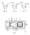
Es ist aus verschiedenen Gründen vorteilhaft, modifizierte Standardkompressionsmaschinen aus der Klima- und Kältetechnik in ORC-Systemen als Expansionsmaschinen anzuwenden, wobei dann der Motor M der Kompressionsmaschine als Generator G fungiert (
In der Verwendung als Kompressor in der Klima- und Kältetechnik dient der Motor M zum Antreiben des Kompressors und der Motor wird durch den über den Motor strömenden kalten Dampf gekühlt (
Zur Steigerung der Effizienz (höherer thermischer Wirkungsgrad) und zur Erweiterung des Einsatzgebietes ist es jedoch zweckmäßig, diese Dampftemperaturen zu erhöhen. Problematisch ist es in Bezug auf einen störungsfreien Betrieb, wenn dem Generator G eine Abdampftemperatur von über 100°C aufgeprägt wird. Dann kann die Grenztemperatur für die Generatorwicklung erreicht oder überschritten werden (beispielsweise 120°C in
Aktuell eingesetzte und verfügbare Expansionsmaschinen sind in ihrer Betriebstemperatur nach oben hin begrenzt. Zum einen wirken sich - wie soeben beschrieben - hohe Temperaturen in der Expansionsmaschine negativ auf den örtlich nahen Generator aus. Für diesen gibt es Grenztemperaturen, die nicht überschritten werden dürfen. Problematisch ist zum anderen die Viskosität der Lagerschmiermittel, die mit höheren Temperaturen abnimmt wodurch sich die Lagerschmierung verschlechtert.Currently used and available expansion machines are limited in their operating temperature at the top. On the one hand - as just described - high temperatures in the expansion machine have a negative effect on the local generator. For this there are limit temperatures, which must not be exceeded. Another problem is the viscosity of the bearing lubricant, which decreases with higher temperatures which causes bearing lubrication to deteriorate.
Um die Abwärme aus einem ORC-Prozess für Heizzwecke, oder als Prozesswärme weiterhin nutzen zu können, muss die Wärme auf einem dafür geeigneten Temperaturniveau abgegeben werden (60-100°C). Dies führt aber bei niedrigen Frischdampftemperaturen zu schlechten Wirkungsgraden des Gesamtsystems. Es ist also vorteilhaft, diesem Effekt mit höheren Expansionsmaschineneintrittstemperaturen entgegenzuwirken. Höhere Temperaturen führen jedoch dazu, dass die Temperaturgrenzen für den Einsatz der Expansionsmaschine (durch Temperaturgrenzen für den Generator) überschritten werden, was nachteilig ist.In order to be able to use the waste heat from an ORC process for heating purposes or as process heat, the heat must be released at a suitable temperature level (60-100 ° C). However, at low live steam temperatures, this leads to poor efficiencies of the overall system. It is therefore advantageous to counteract this effect with higher expansion machine inlet temperatures. Higher temperatures, however, lead to the temperature limits for the use of the expansion machine (by temperature limits for the generator) are exceeded, which is disadvantageous.
Aufgabe der Erfindung ist es, die oben beschriebenen Nachteile zumindest teilweise zu überwinden.The object of the invention is at least partially overcome the disadvantages described above.
Diese Aufgabe wird gelöst durch eine Vorrichtung nach Anspruch 1. Die erfindungsgemäße Vorrichtung umfasst eine Expansionsmaschine zum Erzeugen von mechanischer Energie durch Expandieren von Dampf eines Arbeitsmediums; einen mit einer Welle der Expansionsmaschine verbundenen Generator zum Erzeugen von elektrischer Energie aus mechanischer Energie der Expansionsmaschine; wobei die Expansionsmaschine und der Generator eine bauliche Einheit mit einem Abdampfraum zwischen der Expansionsmaschine und dem Generator bilden, und wobei im Betrieb der Expansionsmaschine in den Abdampfraum expandiertes Arbeitsmedium den Generator kontaktiert; und Mittel zum Zuführen, insbesondere zum Einspritzen, von flüssigem Arbeitsmedium in den Abdampfraum.This object is achieved by a device according to claim 1. The device according to the invention comprises an expansion machine for generating mechanical energy by expanding steam of a working medium; a generator connected to a shaft of the expansion machine for generating electrical energy from mechanical energy of the expansion machine; wherein the expansion machine and the generator form a structural unit with a Abdampfraum between the expansion machine and the generator, and wherein in operation of the expansion machine in the Abdampfraum expanded working medium contacts the generator; and means for supplying, in particular for injecting, liquid working medium into the exhaust-steam space.
Das entspannte Arbeitsmedium (Abdampf) wird nach der Expansionsmaschine durch flüssiges Arbeitsmedium gekühlt. Durch die Zuführung, insbesondere Eindüsung in den Abdampfraum verdampft das flüssige Medium bei Kontakt mit dem heißen Abdampf und senkt somit die Temperatur im entspannten Medium. Der Einsatzbereich der volumetrischen Expansionsmaschine wird erweitert, wodurch diese für höhere Dampfeintrittstemperaturen (z.B. größer als 130°C) angewendet werden kann. Der Generator an der Expansionsmaschine wird ausreichend gekühlt und vor Überhitzung geschützt. Gleichzeitig steigt dessen Wirkungsgrad. Vorteilhaft ist hier ein Temperaturgefälle zwischen Gerator und Abdampf von 20 K oder mehr, weil dann eine gute Kühlung des Generators gewährleistet ist.The relaxed working medium (exhaust steam) is cooled after the expansion machine by liquid working medium. By supplying, in particular injection into the Abdampfraum the liquid medium evaporates on contact with the hot exhaust steam and thus lowers the temperature in the expanded medium. The range of application of the volumetric expansion machine is extended, so that it can be used for higher steam inlet temperatures (eg greater than 130 ° C). The generator on the expansion machine is sufficiently cooled and against overheating protected. At the same time its efficiency increases. A temperature gradient between the generator and the exhaust steam of 20 K or more is advantageous, because then a good cooling of the generator is ensured.
Die erfindungsgemäße Vorrichtung kann dahingehend weitergebildet werden, dass das oder die Mittel zum Zuführen von Arbeitsmedium in den Abdampfraum eine oder mehrere Bohrungen in einem Gehäuse der baulichen Einheit umfassen. Dadurch wird eine Möglichkeit bereitgestellt, Arbeitsmedium in den Abdampfraum zuzuführen.The device according to the invention can be further developed such that the means for supplying working medium into the exhaust-steam space comprises one or more bores in a housing of the structural unit. As a result, a possibility is provided to supply working fluid in the Abdampfraum.
In einer anderen Weiterbildung kann die Welle als Hohlwelle ausgebildet sein und das Mittel zum Zuführen von Arbeitsmedium in den Abdampfraum kann eine oder mehrere Bohrungen in der Hohlwelle umfassen. Dadurch kann das zum Kühlen des Abdampfes zugeführte Arbeitsmedium zentral in den Abdampfraum eingebracht werden.In another embodiment, the shaft may be formed as a hollow shaft and the means for supplying working fluid into the Abdampfraum may include one or more holes in the hollow shaft. As a result, the working medium supplied for cooling the exhaust steam can be centrally introduced into the exhaust steam space.
Das Mittel zum Zuführen von Arbeitsmedium in den Abdampfraum kann gemäß einer anderen Weiterbildung eine oder mehrere Düsen umfassen, die insbesondere an einer oder mehreren der Bohrungen angeordnet sein kann/können, wobei die Düse oder die Düsen insbesondere regelbar ausgebildet sein können. Durch die Düsen wird eine feine Verteilung des zugeführten Arbeitsmediums in den Abdampfraum erzielt werden. Das Einspritzen oder Einsprühen erzeugt Tröpfchen, die im Abdampfraum teilweise oder vollständig verdampfen und durch die dabei aufgenommene Verdampfungswärme dem Abdampf Energie entziehen.The means for supplying working fluid into the Abdampfraum may comprise according to another embodiment, one or more nozzles, which may be arranged in particular on one or more of the holes / can, wherein the nozzle or the nozzles may be formed in particular adjustable. Through the nozzles, a fine distribution of the supplied working medium will be achieved in the Abdampfraum. Injection or spraying produces droplets which partially or completely evaporate in the exhaust-steam space and extract energy from the exhaust-steam by the heat of vaporization absorbed in the process.
Gemäß einer anderen Weiterbildung kann die erfindungsgemäße Vorrichtung oder eine der Weiterbildungen weiterhin eine Turbulenzeinrichtung zum Erzeugen einer turbulenten Strömung im Abdampfraum umfassen. Dadurch wird eine gute Verteilung des zum Kühlen zugeführten Arbeitsmediums erzielt, was eine räumlich gleichmäßigere Kühlung des Abdampfes bewirkt. Durch eine feinere Verteilung des Arbeitsmediums in kleinere Tröpfchen kommt es zudem zu einem schnelleren und vollständigeren Verdampfen des flüssigen Arbeitsmediums im Abdampfraum und daraus resultierend auch zu einer besseren Kühlung des Abdampfs.According to another development, the device according to the invention or one of the further developments may further comprise a turbulence device for generating a turbulent flow in the exhaust-steam space. As a result, a good distribution of the supplied for cooling working medium is achieved, which causes a spatially uniform cooling of the exhaust steam. By a finer distribution of the working medium into smaller droplets, there is also a faster and more complete evaporation of the liquid working medium in the Abdampfraum and, as a result, to a better cooling of the exhaust steam.
Eine andere Weiterbildung besteht darin, dass das Mittel zum Zuführen von Arbeitsmedium in den Abdampfraum eine Zuführleitung für flüssiges Arbeitsmedium in den Abdampfraum umfassen kann.Another development is that the means for supplying working fluid in the Abdampfraum may include a supply line for liquid working fluid in the Abdampfraum.
Dieses kann dahingehend weitergebildet werden, dass das Mittel zum Zuführen von Arbeitsmedium in den Abdampfraum weiterhin eine Blende oder ein Ventil, insbesondere ein gesteuertes oder geregeltes Ventil, zum Einstellen eines Massenstroms des zugeführten Arbeitsmediums in der Zuführleitung aufweist.This can be further developed in that the means for supplying working fluid into the Abdampfraum further comprises a diaphragm or a valve, in particular a controlled or regulated valve for adjusting a mass flow of the supplied working fluid in the supply line.
In einer anderen Weiterbildung kann ein Temperatursensor zum Messen der Dampftemperatur im Abdampfraum oder im Generator zum Messen der Wicklungstemperatur vorgesehen sein, insbesondere ein PTC-Temperatursensor; und es kann optional weiterhin eine Steuer- oder Regeleinrichtung zum Steuern oder Regeln des Ventils oder der Blende in Abhängigkeit von der gemessenen Temperatur bereitgestellt sein, insbesondere zum Ein- und Ausschalten des Massenstroms in der Zuführleitung.In another development, a temperature sensor for measuring the steam temperature in the exhaust steam space or in the generator for measuring the winding temperature may be provided, in particular a PTC temperature sensor; and optionally there can be further provided a control or regulating device for controlling or regulating the valve or the diaphragm as a function of the measured temperature, in particular for switching the mass flow in the supply line on and off.
Die oben genannte Aufgabe wird weiterhin gelöst durch eine ORC-Vorrichtung mit einer erfindungsgemäßen Vorrichtung oder einer deren Weiterbildungen; einer Speisepumpe zum Pumpen von flüssigem Arbeitsmedium zu einem Verdampfer; dem Verdampfer zum Verdampfen des flüssigen Arbeitsmediums; und einem Kondensator zum Kondensieren des aus der baulichen Einheit von Expansionsmaschine und Generator austretenden dampfförmigen Arbeitsmediums.The above object is further achieved by an ORC device with a device according to the invention or one of its developments; a feed pump for pumping liquid working fluid to an evaporator; the evaporator for evaporating the liquid working medium; and a condenser for condensing the vaporous working medium leaving the structural unit of the expansion machine and the generator.
Die erfindungsgemäße ORC-Vorrichtung kann dahingehend weitergebildet werden, dass die Zuführleitung für flüssiges Arbeitsmedium in den Abdampfraum in Fluidverbindung mit einer Leitung zwischen Speisepumpe und Verdampfer steht; oder die Zuführleitung für flüssiges Arbeitsmedium in den Abdampfraum in Fluidverbindung mit einem Zwischenraum einer mehrstufigen Speisepumpe steht; oder die Zuführleitung für flüssiges Arbeitsmedium in den Abdampfraum in Fluidverbindung mit einer Leitung zwischen zwei Speisepumpen einer aufeinanderfolgenden Anordnung aus mehreren Speisepumpen steht. Durch die Anzapfung der mehrstufigen Speisepumpe oder einer Anzapfung zwischen zwei Speisepumpen wird der zusätzliche Energieaufwand gering gehalten. Alternativ dazu kann die Flüssigkeit über eine eigene Pumpe gefördert werden, die z.B. temperaturabhängig eingeschaltet wird.The ORC device according to the invention can be further developed in such a way that the supply line for liquid working medium into the evaporation space is in fluid communication with a line between the feed pump and the evaporator; or the liquid working medium supply line is in fluid communication with a space of a multi-stage feed pump into the exhaust space; or the supply line for liquid working fluid into the exhaust steam space is in fluid communication with a line between two feed pumps of a successive arrangement of a plurality of feed pumps. By tapping the multi-stage feed pump or a tap between two feed pumps is the additional Energy consumption kept low. Alternatively, the liquid can be pumped through its own pump, which is turned on, for example, temperature-dependent.
Gemäß einer anderen Weiterbildung kann eine weitere Zuführleitung zum Zuführen eines Schmiermediums an eine oder mehrere Schmierstellen der Expansionsmaschine; und ein Wärmeübertrager, insbesondere ein Gegenstrom-Plattenwärmeübertrager, zum Kühlen des Schmiermediums mit dem zum Abdampfraum geführten Arbeitsmedium vogesehen sein. Die Lagerschmierung der Expansionsmaschine wird durch die zusätzliche Kühlung des Schmiermediums verbessert.According to another embodiment, a further supply line for supplying a lubricant to one or more lubrication points of the expansion machine; and a heat exchanger, in particular a countercurrent plate heat exchanger, for cooling the lubricating medium with the guided to Abdampfraum working medium be seen. The bearing lubrication of the expansion machine is improved by the additional cooling of the lubricant.
Die oben genannte Aufgabe wird weiterhin gelöst durch ein Verfahren zum Betreiben einer Expansionsmaschine nach Anspruch 12.The above object is further achieved by a method for operating an expansion machine according to claim 12.
Das erfindungsgemäße Verfahren umfasst die Schritte: Erzeugen von mechanischer Energie durch Expandieren von Dampf eines Arbeitsmediums in der Expansionsmaschine; Erzeugen von elektrischer Energie aus mechanischer Energie der Expansionsmaschine mit einem mit einer Welle der Expansionsmaschine verbundenen Generator; wobei die Expansionsmaschine und der Generator eine bauliche Einheit mit einem Abdampfraum zwischen der Expansionsmaschine und dem Generator bilden, und wobei im Betrieb der Expansionsmaschine in den Abdampfraum expandiertes Arbeitsmedium den Generator kontaktiert; und Zuführen, insbesondere Einspritzen, von Arbeitsmedium in den Abdampfraum zum Kühlen des expandierten Dampfes.The method according to the invention comprises the steps of: generating mechanical energy by expanding steam of a working medium in the expansion machine; Generating electrical energy from mechanical energy of the expansion machine with a generator connected to a shaft of the expansion machine; wherein the expansion machine and the generator form a structural unit with a Abdampfraum between the expansion machine and the generator, and wherein in operation of the expansion machine in the Abdampfraum expanded working medium contacts the generator; and feeding, in particular injecting, working fluid into the exhaust steam space for cooling the expanded steam.
Das erfindungsgemäße Verfahren hat die Vorteile, die bereits im Zusammenhang mit der erfindungsgemäßen Vorrichtung beschrieben worden sind.The inventive method has the advantages that have already been described in connection with the device according to the invention.
Das erfindungsgemäße Verfahren kann dahingehend weitergebildet werden, dass der weitere Schritt des Einstellens eines Massenstroms des zugeführten Arbeitsmediums in einer Zuführleitung für flüssiges Arbeitsmedium in den Abdampfraum durchgeführt werden kann.The method according to the invention can be further developed such that the further step of setting a mass flow of the supplied working medium in a supply line for liquid working medium can be carried out in the evaporation space.
Gemäß einer anderen Weiterbildung können die folgenden weiteren Schritte vorgesehen sein: Messen der Dampftemperatur im Abdampfraum; oder Messen einer Wicklungstemperatur des Generators; und Einstellen des Massenstroms des zugeführten Arbeitsmediums mittels Steuern oder Regeln eines Ventils oder einer Blende in der Zuführleitung in Abhängigkeit von der gemessenen Temperatur, insbesondere Ein- und Ausschalten des Massenstroms in der Zuführleitung.According to another embodiment, the following further steps may be provided: measuring the steam temperature in the exhaust steam space; or measuring a winding temperature of the generator; and adjusting the mass flow of the supplied working medium by controlling or regulating a valve or orifice in the supply line in dependence on the measured temperature, in particular switching on and off of the mass flow in the supply line.
In einer anderen Weiterbildung können die folgenden weiteren Schritte vorgesehen sein: Zuführen eines Schmiermediums an eine oder mehrere Schmierstellen der Expansionsmaschine; und Kühlen des Schmiermediums mit dem zum Abdampfraum geführten Arbeitsmedium.In another development, the following further steps can be provided: supplying a lubricant to one or more lubrication points of the expansion machine; and cooling the lubricating medium with the guided to Abdampfraum working fluid.
Die genannten Weiterbildungen können einzeln eingesetzt oder geeignet miteinander kombiniert werden.The said developments can be used individually or combined with each other.
Weitere Merkmale und beispielhafte Ausführungsformen sowie Vorteile der vorliegenden Erfindung werden nachfolgend anhand der Zeichnungen näher erläutert. Es versteht sich, dass die Ausführungsformen nicht den Bereich der vorliegenden Erfindung erschöpfen. Es versteht sich weiterhin, dass einige oder sämtliche der im Weiteren beschriebenen Merkmale auch auf andere Weise miteinander kombiniert werden können.Further features and exemplary embodiments and advantages of the present invention will be explained in more detail with reference to the drawings. It is understood that the embodiments do not exhaust the scope of the present invention. It is further understood that some or all of the features described below may be combined with each other in other ways.
- Figur 1FIG. 1
- zeigt Stand der Technikshows state of the art
- Figur 1AFigure 1A
- zeigt einen Kompressor (Stand der Technik bei Klimaanlagen)shows a compressor (prior art in air conditioners)
- Figur 1BFIG. 1B
- zeigt einen Expander (Stand der Technik in ORC-Anlagen)shows an expander (state of the art in ORC systems)
- Figur 1CFigure 1C
- zeigt einen Expander (Entwicklungsziel ORC-Anlagen)shows an expander (development target ORC systems)
- Figur 2FIG. 2
- zeigt eine Ausführungsform der erfindungsgemäßen Vorrichtungshows an embodiment of the device according to the invention
- Figur 3FIG. 3
- zeigt eine erste Ausführungsform einer erfindungsgemäßen ORC-Vorrichtungshows a first embodiment of an ORC device according to the invention
- Figur 4FIG. 4
- zeigt eine zweite Ausführungsform einer erfindungsgemäßen ORC-Vorrichtungshows a second embodiment of an ORC device according to the invention
- Figur 5FIG. 5
- zeigt eine dritte Ausführungsform einer erfindungsgemäßen ORC-Vorrichtungshows a third embodiment of an ORC device according to the invention
Erfindungsgemäß wird entspanntes Arbeitsmedium (Abdampf) nach der Expansionsmaschine durch flüssiges Arbeitsmedium gekühlt. Durch die Eindüsung in den Dampfraum verdampft das flüssige Arbeitsmedium und senkt somit die Temperatur im entspannten Arbeitsmedium. In einer Weiterbildung wird das Lagerschmiermittel vor der Zugabe auf das Lager mittels des flüssigen Arbeitsmediums gekühlt. In einer weiteren Weiterbildung wird das für die Kühlung verwendete Arbeitsmedium an geeigneter Stufe einer mehrstufigen Kreiselpumpe aus dem Kreislauf abgezweigt.According to the invention, relaxed working medium (exhaust steam) after the expansion machine is cooled by liquid working medium. By injecting into the vapor space, the liquid working medium evaporates and thus lowers the temperature in the expanded working medium. In a further development, the bearing lubricant is cooled before being added to the bearing by means of the liquid working medium. In a further development, the working medium used for the cooling is diverted from the circuit at a suitable stage of a multi-stage centrifugal pump.
Der Einsatzbereich der volumetrischen Expansionsmaschine wird erweitert, wodurch diese für höhere Dampfeintrittstemperaturen (z.B. deutlich größer als 130°C) angewendet werden kann. Der Generator an der Expansionsmaschine oder auch Turbine wird ausreichend gekühlt und vor Überhitzung geschützt. Gleichzeitig steigt dessen Wirkungsgrad. Die Lagerschmierung wird durch die zusätzliche Kühlung des Schmiermediums verbessert. Zur Umsetzung werden nur wenige neue Komponenten benötigt. Dazu gehören eine Verbindungsleitung für das flüssige Medium und eventuell zusätzlich ein Ventil, eine oder mehrere Düsen und ein Wärmeübertrager für das Schmiermittel. Durch die Anzapfung der Speisepumpe wird der zusätzliche Energieaufwand gering gehalten.The range of use of the volumetric expansion machine is broadened, allowing it to be used for higher steam inlet temperatures (e.g., much greater than 130 ° C). The generator on the expansion machine or turbine is sufficiently cooled and protected against overheating. At the same time its efficiency increases. The bearing lubrication is improved by the additional cooling of the lubricant. To implement only a few new components are needed. These include a connecting line for the liquid medium and possibly also a valve, one or more nozzles and a heat exchanger for the lubricant. By tapping the feed pump, the additional energy consumption is kept low.
Die Vorteile der Erfindung bestehen darin, dass der Betrieb von Standardexpansionsmaschinen erweitert werden kann; der Generator vor Überhitzung geschützt wird; der Wirkungsgrad des Generators verbessert wird; die Lagerschmierung verbessert werden kann; höhere Temperaturniveaus genutzt und Nutzwärme aus dem System abgeben werden kann; keine oder nur wenige neue Komponenten erforderlich sind; und kaum zusätzlicher Energieaufwand nötig ist.The advantages of the invention are that the operation of standard expansion machines can be extended; the generator is protected against overheating; the efficiency of the generator is improved; the bearing lubrication can be improved; used higher temperature levels and Useful heat can be released from the system; no or only a few new components are required; and hardly any additional energy is needed.
Insbesondere bei halbhermetischen und hermetischen Schraubenexpansionsmaschinen wird der Generator von entspanntem Dampf überströmt und dadurch gekühlt. Bei hohen Dampftemperaturen (>120°C) ist eine Generatorkühlung nicht mehr gewährleistet. Es ist naheliegend diesem Effekt durch eine Kühlung des strömenden Dampfes entgegenzuwirken. Dazu wird in den Dampf, bevor dieser auf den Generator trifft, flüssiges Arbeitsmedium eingespritzt und über dessen Verdampfungsenthalpie eine starke Auskühlung hervorgerufen, wobei in geringerem Maße auch sensible Wärme aufgenommen wird. Eine Kühlung mit Nutzung der Verdampfungsenthalpie ist effektiver als eine Kühlung ohne Phasenübergang bei ausschließlicher Nutzung von der Wärmekapazität. Für das Arbeitsmedium R245fa, welches aktueller Stand der Technik in ORC-Anlagen ist, sowie bei anderen für höhere Temperaturen geeigneten Medien, sind die Verdampfungsenthalpien um etwa einen Faktor 100 größer als die spezifischen Wärmekapazitäten.Especially in semi-hermetic and hermetic screw expansion machines, the generator is covered by relaxed steam and thereby cooled. At high steam temperatures (> 120 ° C), generator cooling is no longer guaranteed. It is obvious to counteract this effect by cooling the flowing steam. For this purpose, in the steam before it hits the generator, liquid working fluid injected and caused by its enthalpy of vaporization, a strong cooling, and to a lesser extent, sensible heat is absorbed. Cooling using the enthalpy of vaporization is more effective than cooling without phase transition using only the heat capacity. For the working medium R245fa, which is state of the art in ORC systems, as well as for other media suitable for higher temperatures, the evaporation enthalpies are larger by about a factor of 100 than the specific heat capacities.
Für eine Anwendung in ORC-Systemen kann für die Dampfkühlung flüssiges Arbeitsmedium nach der Speisepumpe abgezweigt und in den Dampfraum eingespritzt werden. Die Einspritzung in den Dampfraum kann über eine oder mehrere geeignete Bohrungen erfolgen. Zur besseren Verteilung des flüssigen Mediums und zur schnelleren Verdampfung aufgrund einer feinen Verteilung in kleinen Tropfen ist jedoch der Einsatz einer oder mehrerer Düsen zu empfehlen. Des Weiteren kann das flüssige Kühlmedium über eine Hohlwelle mit Bohrungen in den Dampfraum eingebracht werden. Hierzu bietet sich die Welle zwischen Expansionsmaschine und Generator an. Um die Verteilung zu optimieren, kann in den Dampfraum eine Turbulenzeinrichtung eingebracht werden. Der für die Kühlung notwendige Massenstrom bleibt bei Dampfkühlung bis 10K unter 10% des Dampfmassenstromes. Dieser Massenstrom kann über eine Querschnittsverengung in der Kühlleitung (z.B. über eine Blende oder ein Ventil) eingestellt werden. Bei der Verwendung einer Düse zur Einspritzung kann der Massenstrom über eine geeignete Düse eingestellt werden.For use in ORC systems, liquid working fluid may be diverted downstream of the feed pump for vapor cooling and injected into the vapor space. The injection into the vapor space can take place via one or more suitable bores. For better distribution of the liquid medium and faster evaporation due to a fine distribution in small drops, however, the use of one or more nozzles is recommended. Furthermore, the liquid cooling medium can be introduced via a hollow shaft with holes in the vapor space. For this purpose, the wave between expansion machine and generator offers. In order to optimize the distribution, a turbulence device can be introduced into the vapor space. The mass flow necessary for the cooling remains with steam cooling up to 10K under 10% of the steam mass flow. This mass flow can be adjusted via a cross-sectional constriction in the cooling line (e.g., via a shutter or a valve). When using a nozzle for injection, the mass flow can be adjusted via a suitable nozzle.
Die erfindungsgemäße Verschaltung des ORC-Systems erlaubt höhere Frischdampf-und Abdampftemperaturen bei Einsatz von Standardkomponenten. Durch die Anhebung der Temperaturniveaus ist es möglich, das System in Kraft-Wärme-Kopplung (KWK) zu betreiben. Damit kann die zur Kühlung des Systems verwendete Wärme als Heiz- oder Prozesswärme auf einem Temperaturniveau von ca. 80-100°C und darüber verwendet werden.The interconnection of the ORC system according to the invention allows higher live steam and evaporating temperatures when using standard components. By the Raising the temperature levels, it is possible to operate the system in combined heat and power (CHP). Thus, the heat used to cool the system can be used as heating or process heat at a temperature level of about 80-100 ° C and above.
Der Nutzen der Kühlung kann also erweitert werden, indem das Schmiermedium für die Lager der Expansionsmaschine vor Eintritt in das Lager durch das zur Kühlung verwendete flüssige Arbeitsmedium z.B. in einem Gegenstrom-Plattenwärmeübertrager gekühlt wird, falls das Schmiermittel eine höhere Temperatur als das flüssige Arbeitsmedium besitzt. Wenn weiterhin das Schmiermedium über den Abdampfraum in den Abdampf abgegeben wird, hat die Schmiermittelkühlung auch keinen negativen Einfluss auf die Abdampfkühlung, welcher aufgrund der Erwärmung des zur Kühlung verwendeten flüssigen Arbeitsmediums zunächst zu befürchten wäre. Bei aktuellen Expansionsmaschinen ist durch eine Bohrung zwischen Lagergehäuse und Abdampfraum gewährleistet, dass das Schmiermittel über den Abdampfraum aus dem Lager abgezogen wird. Im Lagergehäuse herrscht ein der Hochdruckseite der Expansionsmaschine ähnlicher Druck. Über die Druckdifferenz zwischen Lagerraum und Niederdruckseite wird das Schmiermedium in den Kältemitteldampf abgesaugt und kann somit den strömenden Arbeitsmediumsdampf mit abkühlen. Die an das flüssige Arbeitsmedium übertragene Wärme wurde dem Schmiermedium entzogen, so dass sich an der Temperatur des Dampfs nach der Mischung von Abdampf, Schmiermedium und flüssigem Arbeitsmedium nichts ändert.The benefit of cooling can thus be extended by the lubricating medium for the bearings of the expansion machine before entering the camp by the for cooling used liquid working medium, for example, in a countercurrent plate heat exchanger is cooled, if the lubricant has a higher temperature than the liquid working medium. Furthermore, if the lubricant is discharged through the Abdampfraum in the exhaust steam, the lubricant cooling also has no negative impact on the exhaust steam cooling, which would initially be feared due to the heating of the liquid working fluid used for cooling. In current expansion machines is ensured by a bore between the bearing housing and Abdampfraum that the lubricant is withdrawn through the Abdampfraum from the camp. In the bearing housing, there is a pressure similar to the high pressure side of the expansion machine. About the pressure difference between the storage room and low pressure side, the lubricant is sucked into the refrigerant vapor and thus can cool the working fluid vapor with. The transferred to the liquid working fluid heat was removed from the lubricating medium, so that nothing changes at the temperature of the steam after the mixture of exhaust steam, lubricating medium and liquid working medium.
Die dargestellten Ausführungsformen sind lediglich beispielhaft und der vollständige Umfang der vorliegenden Erfindung wird durch die Ansprüche definiert.The illustrated embodiments are merely exemplary and the full scope of the present invention is defined by the claims.
Claims (15)
wobei die Zuführleitung für flüssiges Arbeitsmedium in den Abdampfraum in Fluidverbindung mit einer Leitung zwischen Speisepumpe und Verdampfer steht; oder
wobei die Zuführleitung für flüssiges Arbeitsmedium in den Abdampfraum in Fluidverbindung mit einem Zwischenraum einer mehrstufigen Speisepumpe steht; oder
wobei die Zuführleitung für flüssiges Arbeitsmedium in den Abdampfraum in Fluidverbindung mit einer Leitung zwischen zwei Speisepumpen einer aufeinanderfolgenden Anordnung aus mehreren Speisepumpen steht; oder
wobei eine weitere Pumpe zum Pumpen des flüssigen Arbeitsmediums in der Zuführleitung vorgesehen ist.ORC device according to claim 9 in combination with one of claims 6 to 8,
wherein the supply line for liquid working fluid into the Abdampfraum in fluid communication with a line between the feed pump and the evaporator; or
wherein the liquid working medium supply line is in fluid communication with a space of a multi-stage feed pump into the exhaust space; or
wherein the liquid working fluid supply line is in fluid communication with a line between two feed pumps of a sequential multi-feed pumping arrangement in the exhaust steam space; or
wherein a further pump for pumping the liquid working medium is provided in the supply line.
Priority Applications (7)
| Application Number | Priority Date | Filing Date | Title |
|---|---|---|---|
| EP13197480.0A EP2884060B1 (en) | 2013-12-16 | 2013-12-16 | Device and method for operating volumetric expansion machines |
| EP16185062.3A EP3141710B1 (en) | 2013-12-16 | 2013-12-16 | Device and method for operating volumetric expansion machines |
| PCT/EP2014/068735 WO2015090647A2 (en) | 2013-12-16 | 2014-09-03 | Device and method for operating volumetric expansion machines |
| CN201480075515.6A CN105992862B (en) | 2013-12-16 | 2014-09-03 | For running the device and method of volume expanding machine |
| CN201711015646.7A CN107780988A (en) | 2013-12-16 | 2014-09-03 | For running the apparatus and method of volume expanding machine |
| US15/104,923 US10968766B2 (en) | 2013-12-16 | 2014-09-03 | Device and method for operating volumetric expansion machines |
| US17/219,803 US11585231B2 (en) | 2013-12-16 | 2021-03-31 | Device and method for operating volumetric expansion machines |
Applications Claiming Priority (1)
| Application Number | Priority Date | Filing Date | Title |
|---|---|---|---|
| EP13197480.0A EP2884060B1 (en) | 2013-12-16 | 2013-12-16 | Device and method for operating volumetric expansion machines |
Related Child Applications (2)
| Application Number | Title | Priority Date | Filing Date |
|---|---|---|---|
| EP16185062.3A Division EP3141710B1 (en) | 2013-12-16 | 2013-12-16 | Device and method for operating volumetric expansion machines |
| EP16185062.3A Division-Into EP3141710B1 (en) | 2013-12-16 | 2013-12-16 | Device and method for operating volumetric expansion machines |
Publications (2)
| Publication Number | Publication Date |
|---|---|
| EP2884060A1 true EP2884060A1 (en) | 2015-06-17 |
| EP2884060B1 EP2884060B1 (en) | 2020-04-01 |
Family
ID=49884947
Family Applications (2)
| Application Number | Title | Priority Date | Filing Date |
|---|---|---|---|
| EP13197480.0A Active EP2884060B1 (en) | 2013-12-16 | 2013-12-16 | Device and method for operating volumetric expansion machines |
| EP16185062.3A Active EP3141710B1 (en) | 2013-12-16 | 2013-12-16 | Device and method for operating volumetric expansion machines |
Family Applications After (1)
| Application Number | Title | Priority Date | Filing Date |
|---|---|---|---|
| EP16185062.3A Active EP3141710B1 (en) | 2013-12-16 | 2013-12-16 | Device and method for operating volumetric expansion machines |
Country Status (4)
| Country | Link |
|---|---|
| US (2) | US10968766B2 (en) |
| EP (2) | EP2884060B1 (en) |
| CN (2) | CN105992862B (en) |
| WO (1) | WO2015090647A2 (en) |
Families Citing this family (5)
| Publication number | Priority date | Publication date | Assignee | Title |
|---|---|---|---|---|
| US10075045B2 (en) * | 2016-03-29 | 2018-09-11 | Phd, Inc. | Actuator exhaust fluid energy harvester |
| EP3578765B1 (en) | 2018-06-08 | 2022-06-22 | Fludema GmbH | Low pressure steam turbine system and operating method for a turbo set and for a low pressure steam turbine system |
| DE102018209204B4 (en) | 2018-06-08 | 2020-06-18 | fludema GmbH | Operating method for a turbo set, turbo set and low pressure steam turbine system |
| CN111608741B (en) * | 2020-05-29 | 2022-09-16 | 中国科学院上海高等研究院 | ORC system for recycling waste heat of generator |
| US20230193792A1 (en) * | 2021-12-22 | 2023-06-22 | Charles Tuckey | Closed loop steam engine assembly with feedback features and method of operation |
Citations (6)
| Publication number | Priority date | Publication date | Assignee | Title |
|---|---|---|---|---|
| EP0952316A2 (en) * | 1998-04-20 | 1999-10-27 | General Electric Company | Gas turbine inlet air cooling method for combined cycle power plants |
| WO2002090747A2 (en) * | 2001-05-07 | 2002-11-14 | Battelle Memorial Institute | Heat energy utilization system |
| WO2011149916A1 (en) * | 2010-05-28 | 2011-12-01 | General Electric International, Inc | Generating energy from fluid expansion |
| DE202012006055U1 (en) * | 2012-06-25 | 2012-08-01 | Monika Semmler | Device for generating electrical energy by means of an Organic Rankine cycle in conjunction with a turbine generator |
| DE102011054793A1 (en) * | 2011-10-25 | 2013-04-25 | TEC artec GmbH | Desuperheaters |
| US20130098037A1 (en) * | 2011-10-20 | 2013-04-25 | Dresser-Rand Company | Advanced super-critical co2 expander-generator |
Family Cites Families (19)
| Publication number | Priority date | Publication date | Assignee | Title |
|---|---|---|---|---|
| US436216A (en) * | 1890-09-09 | Device for operating oil-wells | ||
| US3024366A (en) * | 1958-06-11 | 1962-03-06 | Yanagimachi Masanosuke | Electric generator system |
| JPS5938440B2 (en) * | 1975-01-31 | 1984-09-17 | 株式会社日立製作所 | fluid rotating machine |
| US4363216A (en) * | 1980-10-23 | 1982-12-14 | Lucien Bronicki | Lubricating system for organic fluid power plant |
| US4740711A (en) * | 1985-11-29 | 1988-04-26 | Fuji Electric Co., Ltd. | Pipeline built-in electric power generating set |
| US6827104B2 (en) * | 2001-10-24 | 2004-12-07 | Mcfarland Rory S. | Seal and valve systems and methods for use in expanders and compressors of energy conversion systems |
| JP2006230145A (en) * | 2005-02-18 | 2006-08-31 | Ebara Corp | Submerged turbine generator |
| US7841306B2 (en) * | 2007-04-16 | 2010-11-30 | Calnetix Power Solutions, Inc. | Recovering heat energy |
| US7638892B2 (en) * | 2007-04-16 | 2009-12-29 | Calnetix, Inc. | Generating energy from fluid expansion |
| EP2290241A1 (en) * | 2009-07-13 | 2011-03-02 | Siemens Aktiengesellschaft | Turbocompressor assembly with a cooling system |
| US8664785B2 (en) * | 2010-09-13 | 2014-03-04 | Ebara International Corporation | Power recovery system using a rankine power cycle incorporating a two-phase liquid-vapor expander with electric generator |
| US9476428B2 (en) * | 2011-06-01 | 2016-10-25 | R & D Dynamics Corporation | Ultra high pressure turbomachine for waste heat recovery |
| US9194758B2 (en) * | 2011-06-20 | 2015-11-24 | General Electric Company | Virtual sensor systems and methods for estimation of steam turbine sectional efficiencies |
| WO2013025341A1 (en) * | 2011-08-12 | 2013-02-21 | Dresser-Rand Company | Parallel cascaded cycle gas expander |
| US9689281B2 (en) * | 2011-12-22 | 2017-06-27 | Nanjing Tica Air-Conditioning Co., Ltd. | Hermetic motor cooling for high temperature organic Rankine cycle system |
| US9024460B2 (en) * | 2012-01-04 | 2015-05-05 | General Electric Company | Waste heat recovery system generator encapsulation |
| US9228588B2 (en) * | 2012-01-06 | 2016-01-05 | Dresser-Rand Company | Turbomachine component temperature control |
| JP2013169029A (en) * | 2012-02-14 | 2013-08-29 | Kobe Steel Ltd | Power generator |
| JP6403271B2 (en) * | 2015-03-23 | 2018-10-10 | 株式会社神戸製鋼所 | Heat recovery power generation system |
-
2013
- 2013-12-16 EP EP13197480.0A patent/EP2884060B1/en active Active
- 2013-12-16 EP EP16185062.3A patent/EP3141710B1/en active Active
-
2014
- 2014-09-03 US US15/104,923 patent/US10968766B2/en active Active
- 2014-09-03 WO PCT/EP2014/068735 patent/WO2015090647A2/en active Application Filing
- 2014-09-03 CN CN201480075515.6A patent/CN105992862B/en active Active
- 2014-09-03 CN CN201711015646.7A patent/CN107780988A/en active Pending
-
2021
- 2021-03-31 US US17/219,803 patent/US11585231B2/en active Active
Patent Citations (6)
| Publication number | Priority date | Publication date | Assignee | Title |
|---|---|---|---|---|
| EP0952316A2 (en) * | 1998-04-20 | 1999-10-27 | General Electric Company | Gas turbine inlet air cooling method for combined cycle power plants |
| WO2002090747A2 (en) * | 2001-05-07 | 2002-11-14 | Battelle Memorial Institute | Heat energy utilization system |
| WO2011149916A1 (en) * | 2010-05-28 | 2011-12-01 | General Electric International, Inc | Generating energy from fluid expansion |
| US20130098037A1 (en) * | 2011-10-20 | 2013-04-25 | Dresser-Rand Company | Advanced super-critical co2 expander-generator |
| DE102011054793A1 (en) * | 2011-10-25 | 2013-04-25 | TEC artec GmbH | Desuperheaters |
| DE202012006055U1 (en) * | 2012-06-25 | 2012-08-01 | Monika Semmler | Device for generating electrical energy by means of an Organic Rankine cycle in conjunction with a turbine generator |
Also Published As
| Publication number | Publication date |
|---|---|
| EP3141710B1 (en) | 2024-02-14 |
| CN105992862A (en) | 2016-10-05 |
| US11585231B2 (en) | 2023-02-21 |
| US20160319691A1 (en) | 2016-11-03 |
| EP3141710A1 (en) | 2017-03-15 |
| WO2015090647A3 (en) | 2016-06-02 |
| CN107780988A (en) | 2018-03-09 |
| EP2884060B1 (en) | 2020-04-01 |
| US10968766B2 (en) | 2021-04-06 |
| US20210215058A1 (en) | 2021-07-15 |
| WO2015090647A2 (en) | 2015-06-25 |
| CN105992862B (en) | 2018-06-12 |
Similar Documents
| Publication | Publication Date | Title |
|---|---|---|
| EP2865854B1 (en) | Device and method for reliable starting of ORC systems | |
| EP2884060B1 (en) | Device and method for operating volumetric expansion machines | |
| DE102011005722B3 (en) | Method for operating a steam cycle process | |
| EP2909452B1 (en) | Apparatus for producing electrical energy with an orc cycle | |
| DE102013009351B3 (en) | Plant for recovery of energy from heat of e.g. waste incinerator, has valves which connect/disconnect vaporizer units to control flow of working fluid, to take heat from working fluid and to pass heated working fluid to workspace | |
| EP2823156B1 (en) | System for storing and outputting thermal energy | |
| EP3006682B1 (en) | Device and method for operating a heating distribution station | |
| EP3118424B1 (en) | Control of orc processes by injection of un-vaporized fluids | |
| DE102006043491B4 (en) | Steam cycle process with improved energy utilization | |
| DE202012006055U1 (en) | Device for generating electrical energy by means of an Organic Rankine cycle in conjunction with a turbine generator | |
| DE102012011167A1 (en) | Rotary piston apparatus for steam engine, has working chamber that is arranged with moveable piston element and is coupled to discharge unit for discharging working medium from working chamber | |
| WO2018166642A1 (en) | Model-based monitoring of the operating state of an expansion machine | |
| DE102012024031B4 (en) | Apparatus and method for converting thermal energy with an expander | |
| DE10260444A1 (en) | Power plant extracting thermal energy from surroundings includes two or three circuits recirculating refrigerant or other material | |
| WO2012152602A1 (en) | Line circuit and method for operating a line circuit for waste-heat utilization of an internal combustion engine | |
| DE2438418A1 (en) | Rotating vane gas compressor for refrigerating plant - has means for injecting the gas in liquid state into the compression chamber | |
| DE102016220634A1 (en) | Waste heat power plant with gradual heat supply | |
| DE102012100645B4 (en) | ORC - Organic Rankine cycle | |
| DE10035289A1 (en) | Device to generate mechanical energy using heat engine; has Stirling motor with warm and cool sides and refrigerator to cool cold side, with cooler connected to evaporator of Stirling motor | |
| EP2951407A2 (en) | Method for operating a low-temperature power plant, and low-temperature power plant itself | |
| EP3015660B1 (en) | Method for operating a thermodynamic cycle process | |
| DE102017215698A1 (en) | Cooling system for a turbine bearing | |
| DE10160593B4 (en) | Thermal power plant | |
| WO2024078669A1 (en) | Heat pump device for energy-efficient generation of a process heat, dryer device for drying material to be dried, and method for operating a heat pump device | |
| DE102019100539A1 (en) | Multi-stage heat pump system with rotary piston machines connected in series |
Legal Events
| Date | Code | Title | Description |
|---|---|---|---|
| PUAI | Public reference made under article 153(3) epc to a published international application that has entered the european phase |
Free format text: ORIGINAL CODE: 0009012 |
|
| 17P | Request for examination filed |
Effective date: 20131216 |
|
| AK | Designated contracting states |
Kind code of ref document: A1 Designated state(s): AL AT BE BG CH CY CZ DE DK EE ES FI FR GB GR HR HU IE IS IT LI LT LU LV MC MK MT NL NO PL PT RO RS SE SI SK SM TR |
|
| AX | Request for extension of the european patent |
Extension state: BA ME |
|
| RAP1 | Party data changed (applicant data changed or rights of an application transferred) |
Owner name: ORCAN ENERGY AG |
|
| R17P | Request for examination filed (corrected) |
Effective date: 20151202 |
|
| RBV | Designated contracting states (corrected) |
Designated state(s): AL AT BE BG CH CY CZ DE DK EE ES FI FR GB GR HR HU IE IS IT LI LT LU LV MC MK MT NL NO PL PT RO RS SE SI SK SM TR |
|
| RIN1 | Information on inventor provided before grant (corrected) |
Inventor name: SCHUSTER, ANDREAS Inventor name: LOERCH, RONI Inventor name: AUMANN, RICHARD Inventor name: LANGER, ROY Inventor name: GRILL, ANDREAS Inventor name: BLUMHARDT, MARCUS |
|
| GRAP | Despatch of communication of intention to grant a patent |
Free format text: ORIGINAL CODE: EPIDOSNIGR1 |
|
| STAA | Information on the status of an ep patent application or granted ep patent |
Free format text: STATUS: GRANT OF PATENT IS INTENDED |
|
| INTG | Intention to grant announced |
Effective date: 20191216 |
|
| RIN1 | Information on inventor provided before grant (corrected) |
Inventor name: LOERCH, RONI Inventor name: SCHUSTER, ANDREAS Inventor name: BLUMHARDT, MARCUS Inventor name: GRILL, ANDREAS Inventor name: AUMANN, RICHARD Inventor name: LANGER, ROY |
|
| GRAS | Grant fee paid |
Free format text: ORIGINAL CODE: EPIDOSNIGR3 |
|
| GRAA | (expected) grant |
Free format text: ORIGINAL CODE: 0009210 |
|
| STAA | Information on the status of an ep patent application or granted ep patent |
Free format text: STATUS: THE PATENT HAS BEEN GRANTED |
|
| AK | Designated contracting states |
Kind code of ref document: B1 Designated state(s): AL AT BE BG CH CY CZ DE DK EE ES FI FR GB GR HR HU IE IS IT LI LT LU LV MC MK MT NL NO PL PT RO RS SE SI SK SM TR |
|
| REG | Reference to a national code |
Ref country code: GB Ref legal event code: FG4D Free format text: NOT ENGLISH |
|
| REG | Reference to a national code |
Ref country code: AT Ref legal event code: REF Ref document number: 1251602 Country of ref document: AT Kind code of ref document: T Effective date: 20200415 Ref country code: CH Ref legal event code: EP |
|
| REG | Reference to a national code |
Ref country code: DE Ref legal event code: R096 Ref document number: 502013014515 Country of ref document: DE |
|
| REG | Reference to a national code |
Ref country code: IE Ref legal event code: FG4D Free format text: LANGUAGE OF EP DOCUMENT: GERMAN |
|
| REG | Reference to a national code |
Ref country code: NL Ref legal event code: FP |
|
| REG | Reference to a national code |
Ref country code: SE Ref legal event code: TRGR |
|
| PG25 | Lapsed in a contracting state [announced via postgrant information from national office to epo] |
Ref country code: BG Free format text: LAPSE BECAUSE OF FAILURE TO SUBMIT A TRANSLATION OF THE DESCRIPTION OR TO PAY THE FEE WITHIN THE PRESCRIBED TIME-LIMIT Effective date: 20200701 |
|
| REG | Reference to a national code |
Ref country code: LT Ref legal event code: MG4D |
|
| PG25 | Lapsed in a contracting state [announced via postgrant information from national office to epo] |
Ref country code: NO Free format text: LAPSE BECAUSE OF FAILURE TO SUBMIT A TRANSLATION OF THE DESCRIPTION OR TO PAY THE FEE WITHIN THE PRESCRIBED TIME-LIMIT Effective date: 20200701 Ref country code: GR Free format text: LAPSE BECAUSE OF FAILURE TO SUBMIT A TRANSLATION OF THE DESCRIPTION OR TO PAY THE FEE WITHIN THE PRESCRIBED TIME-LIMIT Effective date: 20200702 Ref country code: LT Free format text: LAPSE BECAUSE OF FAILURE TO SUBMIT A TRANSLATION OF THE DESCRIPTION OR TO PAY THE FEE WITHIN THE PRESCRIBED TIME-LIMIT Effective date: 20200401 Ref country code: PT Free format text: LAPSE BECAUSE OF FAILURE TO SUBMIT A TRANSLATION OF THE DESCRIPTION OR TO PAY THE FEE WITHIN THE PRESCRIBED TIME-LIMIT Effective date: 20200817 Ref country code: FI Free format text: LAPSE BECAUSE OF FAILURE TO SUBMIT A TRANSLATION OF THE DESCRIPTION OR TO PAY THE FEE WITHIN THE PRESCRIBED TIME-LIMIT Effective date: 20200401 Ref country code: CZ Free format text: LAPSE BECAUSE OF FAILURE TO SUBMIT A TRANSLATION OF THE DESCRIPTION OR TO PAY THE FEE WITHIN THE PRESCRIBED TIME-LIMIT Effective date: 20200401 Ref country code: IS Free format text: LAPSE BECAUSE OF FAILURE TO SUBMIT A TRANSLATION OF THE DESCRIPTION OR TO PAY THE FEE WITHIN THE PRESCRIBED TIME-LIMIT Effective date: 20200801 |
|
| PG25 | Lapsed in a contracting state [announced via postgrant information from national office to epo] |
Ref country code: HR Free format text: LAPSE BECAUSE OF FAILURE TO SUBMIT A TRANSLATION OF THE DESCRIPTION OR TO PAY THE FEE WITHIN THE PRESCRIBED TIME-LIMIT Effective date: 20200401 Ref country code: RS Free format text: LAPSE BECAUSE OF FAILURE TO SUBMIT A TRANSLATION OF THE DESCRIPTION OR TO PAY THE FEE WITHIN THE PRESCRIBED TIME-LIMIT Effective date: 20200401 Ref country code: LV Free format text: LAPSE BECAUSE OF FAILURE TO SUBMIT A TRANSLATION OF THE DESCRIPTION OR TO PAY THE FEE WITHIN THE PRESCRIBED TIME-LIMIT Effective date: 20200401 |
|
| PG25 | Lapsed in a contracting state [announced via postgrant information from national office to epo] |
Ref country code: AL Free format text: LAPSE BECAUSE OF FAILURE TO SUBMIT A TRANSLATION OF THE DESCRIPTION OR TO PAY THE FEE WITHIN THE PRESCRIBED TIME-LIMIT Effective date: 20200401 |
|
| REG | Reference to a national code |
Ref country code: DE Ref legal event code: R097 Ref document number: 502013014515 Country of ref document: DE |
|
| PG25 | Lapsed in a contracting state [announced via postgrant information from national office to epo] |
Ref country code: SM Free format text: LAPSE BECAUSE OF FAILURE TO SUBMIT A TRANSLATION OF THE DESCRIPTION OR TO PAY THE FEE WITHIN THE PRESCRIBED TIME-LIMIT Effective date: 20200401 Ref country code: ES Free format text: LAPSE BECAUSE OF FAILURE TO SUBMIT A TRANSLATION OF THE DESCRIPTION OR TO PAY THE FEE WITHIN THE PRESCRIBED TIME-LIMIT Effective date: 20200401 Ref country code: DK Free format text: LAPSE BECAUSE OF FAILURE TO SUBMIT A TRANSLATION OF THE DESCRIPTION OR TO PAY THE FEE WITHIN THE PRESCRIBED TIME-LIMIT Effective date: 20200401 Ref country code: EE Free format text: LAPSE BECAUSE OF FAILURE TO SUBMIT A TRANSLATION OF THE DESCRIPTION OR TO PAY THE FEE WITHIN THE PRESCRIBED TIME-LIMIT Effective date: 20200401 |
|
| PLBE | No opposition filed within time limit |
Free format text: ORIGINAL CODE: 0009261 |
|
| STAA | Information on the status of an ep patent application or granted ep patent |
Free format text: STATUS: NO OPPOSITION FILED WITHIN TIME LIMIT |
|
| PG25 | Lapsed in a contracting state [announced via postgrant information from national office to epo] |
Ref country code: SK Free format text: LAPSE BECAUSE OF FAILURE TO SUBMIT A TRANSLATION OF THE DESCRIPTION OR TO PAY THE FEE WITHIN THE PRESCRIBED TIME-LIMIT Effective date: 20200401 Ref country code: PL Free format text: LAPSE BECAUSE OF FAILURE TO SUBMIT A TRANSLATION OF THE DESCRIPTION OR TO PAY THE FEE WITHIN THE PRESCRIBED TIME-LIMIT Effective date: 20200401 |
|
| 26N | No opposition filed |
Effective date: 20210112 |
|
| PG25 | Lapsed in a contracting state [announced via postgrant information from national office to epo] |
Ref country code: SI Free format text: LAPSE BECAUSE OF FAILURE TO SUBMIT A TRANSLATION OF THE DESCRIPTION OR TO PAY THE FEE WITHIN THE PRESCRIBED TIME-LIMIT Effective date: 20200401 |
|
| REG | Reference to a national code |
Ref country code: CH Ref legal event code: PL |
|
| PG25 | Lapsed in a contracting state [announced via postgrant information from national office to epo] |
Ref country code: MC Free format text: LAPSE BECAUSE OF FAILURE TO SUBMIT A TRANSLATION OF THE DESCRIPTION OR TO PAY THE FEE WITHIN THE PRESCRIBED TIME-LIMIT Effective date: 20200401 |
|
| PG25 | Lapsed in a contracting state [announced via postgrant information from national office to epo] |
Ref country code: LU Free format text: LAPSE BECAUSE OF NON-PAYMENT OF DUE FEES Effective date: 20201216 Ref country code: IE Free format text: LAPSE BECAUSE OF NON-PAYMENT OF DUE FEES Effective date: 20201216 |
|
| PG25 | Lapsed in a contracting state [announced via postgrant information from national office to epo] |
Ref country code: LI Free format text: LAPSE BECAUSE OF NON-PAYMENT OF DUE FEES Effective date: 20201231 Ref country code: CH Free format text: LAPSE BECAUSE OF NON-PAYMENT OF DUE FEES Effective date: 20201231 |
|
| REG | Reference to a national code |
Ref country code: AT Ref legal event code: MM01 Ref document number: 1251602 Country of ref document: AT Kind code of ref document: T Effective date: 20201216 |
|
| PG25 | Lapsed in a contracting state [announced via postgrant information from national office to epo] |
Ref country code: AT Free format text: LAPSE BECAUSE OF NON-PAYMENT OF DUE FEES Effective date: 20201216 |
|
| PG25 | Lapsed in a contracting state [announced via postgrant information from national office to epo] |
Ref country code: TR Free format text: LAPSE BECAUSE OF FAILURE TO SUBMIT A TRANSLATION OF THE DESCRIPTION OR TO PAY THE FEE WITHIN THE PRESCRIBED TIME-LIMIT Effective date: 20200401 Ref country code: MT Free format text: LAPSE BECAUSE OF FAILURE TO SUBMIT A TRANSLATION OF THE DESCRIPTION OR TO PAY THE FEE WITHIN THE PRESCRIBED TIME-LIMIT Effective date: 20200401 Ref country code: CY Free format text: LAPSE BECAUSE OF FAILURE TO SUBMIT A TRANSLATION OF THE DESCRIPTION OR TO PAY THE FEE WITHIN THE PRESCRIBED TIME-LIMIT Effective date: 20200401 |
|
| PG25 | Lapsed in a contracting state [announced via postgrant information from national office to epo] |
Ref country code: MK Free format text: LAPSE BECAUSE OF FAILURE TO SUBMIT A TRANSLATION OF THE DESCRIPTION OR TO PAY THE FEE WITHIN THE PRESCRIBED TIME-LIMIT Effective date: 20200401 |
|
| PGFP | Annual fee paid to national office [announced via postgrant information from national office to epo] |
Ref country code: SE Payment date: 20221215 Year of fee payment: 10 |
|
| PGFP | Annual fee paid to national office [announced via postgrant information from national office to epo] |
Ref country code: BE Payment date: 20221216 Year of fee payment: 10 |
|
| PGFP | Annual fee paid to national office [announced via postgrant information from national office to epo] |
Ref country code: DE Payment date: 20221223 Year of fee payment: 10 |
|
| PGFP | Annual fee paid to national office [announced via postgrant information from national office to epo] |
Ref country code: GB Payment date: 20231220 Year of fee payment: 11 |
|
| PGFP | Annual fee paid to national office [announced via postgrant information from national office to epo] |
Ref country code: RO Payment date: 20231207 Year of fee payment: 11 Ref country code: NL Payment date: 20231222 Year of fee payment: 11 Ref country code: IT Payment date: 20231227 Year of fee payment: 11 Ref country code: FR Payment date: 20231220 Year of fee payment: 11 |
|
| PGFP | Annual fee paid to national office [announced via postgrant information from national office to epo] |
Ref country code: BE Payment date: 20231222 Year of fee payment: 11 |