EP2884036A1 - Seal comprising at least one fixing bracket and at least stop for mounting on the edge of a groove in a door leaf or the like - Google Patents
Seal comprising at least one fixing bracket and at least stop for mounting on the edge of a groove in a door leaf or the like Download PDFInfo
- Publication number
- EP2884036A1 EP2884036A1 EP14195217.6A EP14195217A EP2884036A1 EP 2884036 A1 EP2884036 A1 EP 2884036A1 EP 14195217 A EP14195217 A EP 14195217A EP 2884036 A1 EP2884036 A1 EP 2884036A1
- Authority
- EP
- European Patent Office
- Prior art keywords
- seal
- leg
- housing
- stop
- seal according
- Prior art date
- Legal status (The legal status is an assumption and is not a legal conclusion. Google has not performed a legal analysis and makes no representation as to the accuracy of the status listed.)
- Granted
Links
- 238000007789 sealing Methods 0.000 description 8
- 238000009413 insulation Methods 0.000 description 2
- 239000003550 marker Substances 0.000 description 2
- 240000001439 Opuntia Species 0.000 description 1
- 235000004727 Opuntia ficus indica Nutrition 0.000 description 1
- 230000002349 favourable effect Effects 0.000 description 1
- 239000000463 material Substances 0.000 description 1
Images


Classifications
-
- E—FIXED CONSTRUCTIONS
- E06—DOORS, WINDOWS, SHUTTERS, OR ROLLER BLINDS IN GENERAL; LADDERS
- E06B—FIXED OR MOVABLE CLOSURES FOR OPENINGS IN BUILDINGS, VEHICLES, FENCES OR LIKE ENCLOSURES IN GENERAL, e.g. DOORS, WINDOWS, BLINDS, GATES
- E06B7/00—Special arrangements or measures in connection with doors or windows
- E06B7/16—Sealing arrangements on wings or parts co-operating with the wings
- E06B7/18—Sealing arrangements on wings or parts co-operating with the wings by means of movable edgings, e.g. draught sealings additionally used for bolting, e.g. by spring force or with operating lever
- E06B7/20—Sealing arrangements on wings or parts co-operating with the wings by means of movable edgings, e.g. draught sealings additionally used for bolting, e.g. by spring force or with operating lever automatically withdrawn when the wing is opened, e.g. by means of magnetic attraction, a pin or an inclined surface, especially for sills
- E06B7/215—Sealing arrangements on wings or parts co-operating with the wings by means of movable edgings, e.g. draught sealings additionally used for bolting, e.g. by spring force or with operating lever automatically withdrawn when the wing is opened, e.g. by means of magnetic attraction, a pin or an inclined surface, especially for sills with sealing strip being moved to a retracted position by elastic means, e.g. springs
Abstract
Dichtung umfassend ein Gehäuse (1) und wenigstens einen Befestigungswinkel (2) zur Befestigung des Gehäuses (1) und somit der Dichtung an einem Türblatt (T) o. ä., wobei die Dichtung (1) wenigstens einen Anschlag (12, 24) aufweist, durch den die Dichtung derart positionierbar ist, dass in einem an einem Türblatt (T) montierten Zustand der Dichtung das Gehäuse (1) der Dichtung nicht oder nur geringfügig über eine Kante (K) der Nut hervorsteht.A seal comprising a housing (1) and at least one mounting bracket (2) for fastening the housing (1) and thus the seal on a door leaf (T) o. Ä., Wherein the seal (1) at least one stop (12, 24) by which the seal is positionable such that in a mounted on a door leaf (T) state of the seal, the housing (1) of the seal does not or only slightly beyond an edge (K) of the groove protrudes.
Description
Die vorliegende Erfindung betrifft eine Dichtung umfassend wenigstens einen Befestigungswinkel zur Befestigung der Dichtung der Kante einer Nut derart, dass ein Gehäuse der Dichtung nicht über die Kante der Nut hervorsteht.The present invention relates to a seal comprising at least one mounting bracket for fixing the seal of the edge of a groove such that a housing of the seal does not protrude beyond the edge of the groove.
Aus dem Dokument
Aus dem Dokument
Die in dem Dokument
Vor dem Hintergrund der Offenbarung des Dokumentes
Diese Aufgabe wird erfindungemäß dadurch gelöst, dass die Dichtung wenigstens einen Anschlag aufweist, durch den die Dichtung derart positionierbar ist, dass in einem an einem Türblatt montierten Zustand der Dichtung das Gehäuse der Dichtung nicht oder nur geringfügig über eine Kante der Nut hervorsteht.This object is achieved according erfindungemäß in that the seal has at least one stop by which the seal is positioned so that in a mounted on a door leaf condition of the seal, the housing of the seal does not or only slightly protrudes beyond an edge of the groove.
"Geringfügig hervorstehen" in diesem Sinne bedeutet zum Beispiel, dass das Gehäuse um die Materialstärke einer Wand des Gehäuses über die Kante der Nut hervorstehen kann."Slightly protruding" in this sense means, for example, that the housing can protrude beyond the edge of the groove by the thickness of a wall of the housing.
Der wenigstens eine Befestigungswinkel ist an einem schlossseitigen oder bandseitigen Ende des Gehäuses mit diesem verbunden. Als Schlossseite wird dabei die Seite der Dichtung bezeichnet, welche nach einer Montage der Dichtung an der Schlossseite des Türblattes liegt. Als Bandseite der Dichtung wird die Seite der Dichtung bezeichnet, die nach der Montage der Dichtung an der Bandseite der Dichtung liegt.The at least one mounting bracket is connected to a lock-side or belt-side end of the housing with this. As the lock side while the side of the seal is referred to, which is after mounting the seal on the lock side of the door leaf. The hinge side of the seal is the side of the seal that lies after the assembly of the seal on the hinge side of the seal.
Der Befestigungswinkel kann einen ersten Schenkel aufweisen, der für die Befestigung an dem Türblatt geeignet und eingerichtet ist. In oder an diesem Schenkel kann wenigstens eine Struktur vorgesehen sein, die der Befestigung des ersten Schenkels an dem Türblatt dient. Eine solche Struktur kann zum Beispiel ein Loch in dem Schenkel sein.The mounting bracket may include a first leg suitable and adapted for attachment to the door panel. At least one structure may be provided in or on this leg, which serves to fasten the first leg to the door leaf. Such a structure may be, for example, a hole in the leg.
Der Befestigungswinkel kann einen zweiten Schenkel aufweisen, der mit dem Gehäuse verbunden werden kann. Die Verbindung zwischen dem zweiten Schenkel kann zum Beispiel durch Formschluss und/oder durch Kraftschluss hergestellt werden.The mounting bracket may have a second leg that can be connected to the housing. The connection between the second leg can be made for example by positive engagement and / or by frictional connection.
Der wenigstens eine Anschlag kann in einer Ebene parallel zu einer Ebene angeordnet sein, in welcher der zweite Schenkel des Befestigungswinkels liegt. Er könnte in einer Ebene parallel zu einer Ebene angeordnet sein, in welcher ein Steg des U-förmigen oder H-förmigen Gehäuses liegt.The at least one stop may be arranged in a plane parallel to a plane in which the second leg of the mounting bracket is located. It could be arranged in a plane parallel to a plane in which a ridge of the U-shaped or H-shaped housing is located.
Der Anschlag kann einen runden oder einen eckigen, insbesondere einen rechteckigen Querschnitt aufweisen.The stop may have a round or angled, in particular a rectangular cross-section.
Der wenigstens eine Anschlag ist vorzugsweise mit einem Abstand zum zweiten Schenkel vorgesehen.The at least one stop is preferably provided at a distance from the second leg.
Der Abstand des zweiten Schenkels zum wenigstens einen Anschlag kann dem Abstand zwischen einem Verbindungspunkt des zweiten Schenkels des Befestigungswinkels mit dem Gehäuse der Dichtung und einem freien Ende eines Schenkels des im Wesentlichen U-förmigen oder H-förmigen Gehäuses entsprechen. Das freie Ende kann bei einer Montage der Dichtung am unteren Ende eines Türflügels insbesondere das bodenseitige Ende des Schenkels sein. Wird die Dichtung an einem oberen Ende eines Türblatts montiert um einen über dem Türblatt liegenden Spalt abzudichten, kann das freie Ende des Schenkels ein deckenseitiges Ende des Schenkels des Gehäuses sein.The distance of the second leg from the at least one stop may correspond to the distance between a connection point of the second leg of the mounting bracket with the housing of the seal and a free end of a leg of the substantially U-shaped or H-shaped housing. The free end may be in a mounting of the seal at the lower end of a door, in particular the bottom end of the leg. When the gasket is mounted to an upper end of a door panel to seal a gap over the door leaf, the free end of the leg may be a ceiling end of the leg of the housing.
Eine erfindungsgemäße Dichtung kann so ausgestaltet sein, dass der zweite Schenkel und der wenigstens eine Anschlag in einer Projektion in die Ebene, in welcher der zweite Schenkel liegt, nebeneinander liegen.A seal according to the invention can be designed such that the second leg and the at least one stop in a projection in the plane in which the second leg is located next to each other.
Bei einer bevorzugten Ausführung der Erfindung ist der wenigstens eine Anschlag oder einer der Anschläge an dem wenigstens einen Befestigungswinkel vorgesehen. Der wenigstens eine Anschlag und der zweite Schenkel können über einen Steg des Befestigungswinkels miteinander verbunden sein. Vorzugsweise liegt dieser Steg in der gleichen Ebene wie der erste Schenkel oder in einer Ebene parallel zu der Ebene, in welcher der erste Schenkel liegt.In a preferred embodiment of the invention, the at least one stop or one of the stops is provided on the at least one mounting bracket. The at least one stop and the second leg can be connected to each other via a web of the mounting bracket. Preferably, this web lies in the same plane as the first leg or in a plane parallel to the plane in which the first leg lies.
Ferner ist es möglich, dass der Anschlag und ein Ende eines Schenkels des im Wesentlichen U-förmigen oder H-förmigen Gehäuses aneinander stoßen.Further, it is possible that the abutment and an end of a leg of the substantially U-shaped or H-shaped housing abut each other.
Der Befestigungswinkel kann zwei Anschläge umfassen, die in einer Projektion in die Ebene, in welcher der zweite Schenkel liegt, zu beiden Seiten des zweiten Schenkels liegen können. Die beiden Anschläge können eine gabelartige Struktur bilden. Die beiden Anschläge können einen Abstand zueinander haben, der der Breite des Gehäuses entspricht oder etwas größer oder kleiner als diese Breite ist.The mounting bracket may include two stops that may lie on either side of the second leg in a projection in the plane in which the second leg is located. The two stops can form a fork-like structure. The two stops may have a distance from one another which corresponds to the width of the housing or is slightly larger or smaller than this width.
Bei einer anderen bevorzugten Ausführung der Erfindung ist der wenigstens eine Anschlag oder einer der Anschläge an dem Gehäuse vorgesehen.In another preferred embodiment of the invention, the at least one stop or one of the stops is provided on the housing.
Das Gehäuse kann ein Hutprofil haben.The housing may have a hat profile.
Ferner ist es möglich, dass wenigstens ein Anschlag an ein Ende eines Schenkels des ansonsten vorzugsweise im Wesentlichen U-förmigen oder H-förmigen Gehäuses angeschlossen ist. Dieser Anschlag kann um ca. 90° gegenüber dem Schenkel des Gehäuses abgewinkelt sein.Furthermore, it is possible that at least one stop is connected to one end of a leg of the otherwise preferably substantially U-shaped or H-shaped housing. This Stop can be angled at approximately 90 ° with respect to the leg of the housing.
Die Erfindung wird unter Bezugnahme auf die beiliegenden Abbildungen näher beschrieben. Es zeigt:
- Fig. 1
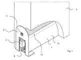
- eine Anordnung mit einem unteren Ende eines Türblatts und einer darin montierten erfindungsgemäßen Dichtung in teilgeschnittener, perspektivischer Darstellung,
- Fig. 2
- die Anordnung aus
Fig. 1 in einer Ansicht von vorne, - Fig. 3
- die Anordnung aus
Fig. 1 in einer Seitenansicht mit einer Markierung der Schnittlinie I-I des inFig. 1 dargestellten Teilschnitts, - Fig. 4
- die Anordnung aus
Fig. 1 in einem Schnitt entlang der inFig. 3 dargestellten Linie IV-IV in vereinfachter Darstellung, - Fig. 5
- einen Befestigungswinkel der in den
Fig. 1 bis 4 dargestellten Dichtung in perspektivischer Darstellung, - Fig. 6
- eine weiteren Anordnung mit einem unteren Ende eines Türblatts und einer darin montierten erfindungsgemäßen Dichtung in teilgeschnittener, perspektivischer Darstellung,
- Fig. 7
- die Anordnung aus
Fig. 6 in einer Seitenansicht mit einer Markierung der Schnittlinie VI-VI des inFig. 6 dargestellten Teilschnitts, - Fig. 8
- die Anordnung aus
Fig. 6 in einem Teilschnitt entlang der inFig. 7 dargestellten Linie VIII-VIII in vereinfachter Darstellung - Fig. 9
- einen Befestigungswinkel der in den
Fig. 6 bis 8 dargestellten Dichtung in perspektivischer Darstellung und - Fig. 10
- eine Anordnung ähnlich der aus
Fig. 1 in einer Seitenansicht mit einer Variante des inFig. 5 dargestellten Befestigungswinkels.
- Fig. 1
- an arrangement with a lower end of a door leaf and a seal according to the invention mounted therein in a partially cutaway perspective view,
- Fig. 2
- the arrangement
Fig. 1 in a view from the front, - Fig. 3
- the arrangement
Fig. 1 in a side view with a marker of the section line II of inFig. 1 partial section, - Fig. 4
- the arrangement
Fig. 1 in a section along the inFig. 3 represented line IV-IV in a simplified representation, - Fig. 5
- a mounting bracket in the
Fig. 1 to 4 illustrated seal in perspective view, - Fig. 6
- a further arrangement with a lower end of a door leaf and a seal according to the invention mounted therein in a partially cutaway perspective view,
- Fig. 7
- the arrangement
Fig. 6 in a side view with a marker of the section line VI-VI of inFig. 6 partial section, - Fig. 8
- the arrangement
Fig. 6 in a partial section along the inFig. 7 illustrated line VIII-VIII in a simplified representation - Fig. 9
- a mounting bracket in the
Fig. 6 to 8 seal shown in perspective and - Fig. 10
- an arrangement similar to that of
Fig. 1 in a side view with a variant of inFig. 5 illustrated mounting bracket.
Die in den Figuren dargestellten Dichtungen haben große Ähnlichkeit. Es werden zunächst anhand der ersten, in den
Die erste Dichtung 1 ist in einer Nut an dem unteren Ende eines Türblatts montiert und dient der Abdichtung eines Luftspaltes zwischen dem Türblatt und einem Fußboden in einem geschlossenen Zustand einer Tür. Bei der ersten Dichtung 1 handelt es sich um eine sogenannte automatische Türdichtung.The
Die erste Dichtung weist ein Gehäuse 1 auf, welches einen im wesentlichen U-förmigen Querschnitt hat. Es weist daher einen Steg 11 und zwei Schenkel 10 auf. An der Innenseite der Schenkel sind mit nur kleinem Abstand zum Steg 11, parallel zum Steg 1 verlaufende Kragen 13 vorgesehen.The first seal has a
Das Gehäuse 1 der Dichtung ist am Türblatt befestigt. Dazu sind zwei Befestigungswinkel 2 vorgesehen. Die Befestigungswinkel 2 weisen zwei Schenkel 21, 22 auf, die in einem Winkel von ca. 90° zueinander stehen. Ein erster der beiden Schenkel 21, 22 jedes der beiden Befestigungswinkel 2, nämlich der Schenkel 21, weist je ein Loch 23 auf. Durch diese Löcher 23 ist je eine Schraube 3 geführt, mit denen die Befestigungswinkel 2 an Schmalseiten des Türblatts T befestigt sind. Die zweiten Schenkel 22 sind an der Bandseite oder der Schlossseite in das Gehäuse 1 eingesteckt und zwar zwischen dem Steg 11 und den Kragen 13. Der zweite Schenkel dient so einer formschlüssigen Befestigung des Gehäuesesl an den zweiten Schenkeln 22.The
In dem Gehäuse 1 ist ein Mechanismus vorgesehen, der mit dem Gehäuse 1 verbunden ist und von dem lediglich ein Auslöser 4 dargestellt ist. Der Mechanismus trägt ein Halteprofil 6. An dem Halteprofil 6 ist ein elastomeres Dichtungsprofil 5 befestigt. Das Halteprofil und das Dichtprofil zusammen werden als Dichtleiste bezeichnet. Durch eine Betätigung des Mechanismus kann die Dichtleiste gegenüber dem Gehäuse verschoben werden. Durch eine Kraft auf den Auslöser 4 kann die Dichtleiste 5, 6 nach unten verschoben werden. Die Dichtleiste 5, 6, insbesondere das Dichtprofil 5 liegen dann am Boden an und der Luftspalt zwischen dem Türblatt T und dem Fußboden ist abgedichtet. Wird der Auslöser 4 entlastet, kann die Dichtleiste 5, 6 durch eine nicht dargestellte Feder nach oben verschoben werden. Die Dichtung ist dann vom Fußboden frei und das Türblatt T kann bewegt werden.In the
Insoweit trifft die Beschreibung auf die erste wie die zweite Dichtung zu.In that regard, the description applies to the first as well as the second seal.
Das Gehäuse 1 der ersten Dichtung ist in der Nut des Türblatts T so befestigt, dass das Gehäuse 1 vollständig in der Nut aufgenommen ist und das freie Enden der Schenkel 22 bündig mit einer Kante der Nut und dadurch mit einer Unterseite des Türblatts T abschließt. Das wird dadurch sichergestellt, dass die Dichtung Anschläge 24 aufweist, die Teil der Befestigungswinkel 2 sind. Jeweils zwei Anschläge 24 sind an einem Befestigungswinkel 2 vorgesehen. Die Anschläge 24 liegen in einer Ebene parallel zu dem zweite Schenkel 22 und jeder Anschlag 24 ist über einen Steg 23 mit dem ersten Schenkel 21 und dem zweiten Schenkel 22 eines Befestigungswinkels verbunden. Der Steg 23 liegt in der Ebene des ersten Schenkels. Die Stege 23 eines Befestigungswinkels liegen parallel zueinander und haben einen Abstand zueinander, der in etwa der Breite des Gehäuses 1 entspricht. Den gleichen Abstand zueinander haben die Anschläge 24, die ebenfalls parallel zu einander liegen. Die Ebene, in welcher der zweite Schenkel 22 liegt, und die Ebene, in welcher die Anschläge 24 liegen, haben einen Abstand zueinander, der in etwa dem Abstand der auf der Seite des Stegs 11 des Gehäuses 1 der Dichtung liegenden Oberfläche der Kragen 13, an welcher die zweiten Schenkel 22 der Befestigungswinkel 2 anliegen, zu den freien Enden der Schenkel 10 des Gehäuses 1 entspricht.The
Das Gehäuse 1 der zweiten Dichtung überragt im Unterschied zur ersten Dichtung die Nut in dem Türblatt T geringfügig, und zwar um die Material- oder Wandstärke von Anschlägen 12, die an den dem Steg 11 abgewandten Enden der Schenkel 10 des Gehäuses 1 angeschlossen sind. Das Gehäuse hat im Querschnitt ein Hutprofil, wobei die Krempe des durch das Profil nachgeahmten Hutes die Anschläge 12 bildet. Diese Anschläge 12 liegen bei montierter zweiter Dichtung an der Unterseite des Türblattes T an.In contrast to the first seal, the
Der Befestigungswinkel 2 der zweiten Dichtung kann dagegen auf bekannte Art und Weise geformt sein und - wie insbesondere in
Die in der
Claims (17)
dadurch gekennzeichnet, dass
die Dichtung (1) wenigstens einen Anschlag (12, 24) aufweist, durch den die Dichtung derart positionierbar ist, dass in einem an einem Türblatt (T) montierten Zustand der Dichtung das Gehäuse (1) der Dichtung nicht oder nur geringfügig über eine Kante (K) der Nut hervorsteht.A seal comprising a housing (1) and at least one mounting bracket (2) for fastening the housing (1) and thus the seal on a door leaf (T) o. Ä.,
characterized in that
the seal (1) has at least one stop (12, 24) by means of which the seal can be positioned such that in a state of the seal mounted on a door leaf (T) the housing (1) of the seal does not or only slightly over an edge (K) of the groove protrudes.
Applications Claiming Priority (1)
| Application Number | Priority Date | Filing Date | Title |
|---|---|---|---|
| DE201320105687 DE202013105687U1 (en) | 2013-12-13 | 2013-12-13 | Seal comprising at least one mounting bracket and at least one stop for mounting on the edge of a groove in a door leaf or the like. |
Publications (2)
| Publication Number | Publication Date |
|---|---|
| EP2884036A1 true EP2884036A1 (en) | 2015-06-17 |
| EP2884036B1 EP2884036B1 (en) | 2019-08-28 |
Family
ID=52023186
Family Applications (1)
| Application Number | Title | Priority Date | Filing Date |
|---|---|---|---|
| EP14195217.6A Active EP2884036B1 (en) | 2013-12-13 | 2014-11-27 | Seal comprising at least one fixing bracket and at least stop for mounting on the edge of a groove in a door leaf or the like |
Country Status (4)
| Country | Link |
|---|---|
| EP (1) | EP2884036B1 (en) |
| CN (1) | CN104863478B (en) |
| DE (1) | DE202013105687U1 (en) |
| DK (1) | DK2884036T3 (en) |
Families Citing this family (3)
| Publication number | Priority date | Publication date | Assignee | Title |
|---|---|---|---|---|
| DE202014101295U1 (en) | 2014-03-20 | 2015-07-01 | Athmer Ohg | Sealing for doors for sealing an air gap between a door leaf on the one hand and a door frame, a floor, a ceiling, a fall or the like. on the other hand |
| CN105156000B (en) * | 2015-09-30 | 2017-03-22 | 江苏肯帝亚森工科技股份有限公司 | Dustproof and sound-isolation device and dustproof sound-isolation door with same |
| DE102015118174A1 (en) * | 2015-10-23 | 2017-04-27 | Huga Hubert Gaisendrees KG | Sealing device for a sliding door and sliding door provided therewith |
Citations (3)
| Publication number | Priority date | Publication date | Assignee | Title |
|---|---|---|---|---|
| EP0338974A2 (en) | 1988-04-19 | 1989-10-25 | " Planet" Matthias Jaggi | Sealing-arrangement for doors without sill |
| EP1439278A2 (en) | 2003-01-08 | 2004-07-21 | Firma F. Athmer | Seal, in particular contact seal or automatically lowerable floor seal for doors with adjustable mounting |
| EP1122394B1 (en) | 2000-02-07 | 2005-12-07 | Planet GDZ AG | Door wing for a door without a sill |
Family Cites Families (13)
| Publication number | Priority date | Publication date | Assignee | Title |
|---|---|---|---|---|
| US1422569A (en) * | 1921-05-23 | 1922-07-11 | John W Hammes | Floating weather strip |
| DE804248C (en) * | 1949-12-01 | 1951-04-19 | Otto Kachel | Sealing device on doors |
| DE1791375U (en) * | 1959-03-28 | 1959-07-02 | Leo Beck | DOOR LOWER EDGE SEAL FOR THRESHOLD DOORS. |
| FR1585622A (en) * | 1968-06-17 | 1970-01-30 | ||
| DE1996239U (en) * | 1968-08-22 | 1968-11-07 | Joachim Gittel | WATER REPELLENT PROFILE FOR ALL KINDS OF WOODEN WINDOWS |
| CH709210B1 (en) * | 2001-02-15 | 2015-08-14 | Planet Gdz Ag | An apparatus for sealing the lower end face of a threshold-free door. |
| DE20219174U1 (en) * | 2002-12-11 | 2003-03-06 | Athmer Fa F | Seal, in particular self-lowering floor seal for doors |
| CN2625544Y (en) * | 2003-06-18 | 2004-07-14 | 马龙建筑及机械(天津)有限公司 | Built-in lifting automatic sealing strip on base of door |
| DE202004007565U1 (en) * | 2004-05-07 | 2005-09-22 | Sylid Systemlogistik Und Industriedienstleistung Gmbh | Draft excluder, for doors and windows, has a spring strip to move the holding rail down and up as the door/window is closed and opened using low pressures for the movements |
| DE202005011984U1 (en) * | 2005-07-30 | 2005-10-13 | Fa. F. Athmer | Sealing arrangement for sliding door has closing mechanism with magnetic element drawing door panel into closed position |
| DE102005047854A1 (en) * | 2005-10-05 | 2007-04-12 | Fa. F. Athmer | Gaskets, methods and apparatus for mounting the gaskets and doors with the gaskets |
| CN2866770Y (en) * | 2006-01-26 | 2007-02-07 | 张建萍 | Up-down automatic fireproofing seal strap on door bottom edge |
| CN202937150U (en) * | 2012-10-15 | 2013-05-15 | 天津市佐佳奇装饰材料制造有限公司 | Automatic door bottom sealing device |
-
2013
- 2013-12-13 DE DE201320105687 patent/DE202013105687U1/en not_active Expired - Lifetime
-
2014
- 2014-11-27 EP EP14195217.6A patent/EP2884036B1/en active Active
- 2014-11-27 DK DK14195217T patent/DK2884036T3/en active
- 2014-12-11 CN CN201410752364.5A patent/CN104863478B/en active Active
Patent Citations (3)
| Publication number | Priority date | Publication date | Assignee | Title |
|---|---|---|---|---|
| EP0338974A2 (en) | 1988-04-19 | 1989-10-25 | " Planet" Matthias Jaggi | Sealing-arrangement for doors without sill |
| EP1122394B1 (en) | 2000-02-07 | 2005-12-07 | Planet GDZ AG | Door wing for a door without a sill |
| EP1439278A2 (en) | 2003-01-08 | 2004-07-21 | Firma F. Athmer | Seal, in particular contact seal or automatically lowerable floor seal for doors with adjustable mounting |
Also Published As
| Publication number | Publication date |
|---|---|
| CN104863478B (en) | 2019-03-22 |
| EP2884036B1 (en) | 2019-08-28 |
| DE202013105687U1 (en) | 2015-03-16 |
| DK2884036T3 (en) | 2019-11-11 |
| CN104863478A (en) | 2015-08-26 |
Similar Documents
| Publication | Publication Date | Title |
|---|---|---|
| DE102016123230B3 (en) | Hinge arrangement for a control cabinet housing and a corresponding control cabinet housing | |
| DE102006024146A1 (en) | Gaskets in particular for a sliding door and sealing arrangement | |
| EP2884036B1 (en) | Seal comprising at least one fixing bracket and at least stop for mounting on the edge of a groove in a door leaf or the like | |
| EP2088337A2 (en) | Profile and profile system | |
| DE102010049782A1 (en) | Hollow profile strip for installing profile frame for protective grid, has multiple functional compartments formed between profile cover surface and profile base for receiving multiple functional elements | |
| EP1439278A2 (en) | Seal, in particular contact seal or automatically lowerable floor seal for doors with adjustable mounting | |
| EP1898041B1 (en) | Process and device for mounting attachments to building frames | |
| EP1335099A2 (en) | Sealing arrangements for a door or a window | |
| DE102007008667B4 (en) | Fastening device for an attachment element | |
| EP3692611A1 (en) | Arrangement for positioning a flat part on a switch cabinet rack, and corresponding method | |
| DE3606812A1 (en) | Lining for a door sill of a motor vehicle | |
| EP2708693A1 (en) | Sliding leaf frame | |
| EP2946955B1 (en) | Assembly consisting of a composite part and frame part of a vehicle door window | |
| EP0620351A1 (en) | Door closer | |
| DE19832379C2 (en) | Sunroof for a motor vehicle | |
| DE102016218262B4 (en) | skylight | |
| EP3071896A1 (en) | Holding device for a housing and method for mounting the housing using the holding device | |
| DE10339333B4 (en) | Floor spring | |
| EP2754817A2 (en) | Fixing plate | |
| EP2787160B1 (en) | Seal for a bolt and seal assembly with such a seal | |
| DE10354310A1 (en) | Seal for rising/falling door has screw-locked limited lateral slide slip action | |
| EP2256279B1 (en) | Closing part for closing the side of a covering rail | |
| DE102011120118B4 (en) | fitting | |
| EP1072751A2 (en) | Door with floor seal | |
| DE102016218256B4 (en) | skylight |
Legal Events
| Date | Code | Title | Description |
|---|---|---|---|
| PUAI | Public reference made under article 153(3) epc to a published international application that has entered the european phase |
Free format text: ORIGINAL CODE: 0009012 |
|
| 17P | Request for examination filed |
Effective date: 20141127 |
|
| AK | Designated contracting states |
Kind code of ref document: A1 Designated state(s): AL AT BE BG CH CY CZ DE DK EE ES FI FR GB GR HR HU IE IS IT LI LT LU LV MC MK MT NL NO PL PT RO RS SE SI SK SM TR |
|
| AX | Request for extension of the european patent |
Extension state: BA ME |
|
| R17P | Request for examination filed (corrected) |
Effective date: 20151103 |
|
| RBV | Designated contracting states (corrected) |
Designated state(s): AL AT BE BG CH CY CZ DE DK EE ES FI FR GB GR HR HU IE IS IT LI LT LU LV MC MK MT NL NO PL PT RO RS SE SI SK SM TR |
|
| STAA | Information on the status of an ep patent application or granted ep patent |
Free format text: STATUS: EXAMINATION IS IN PROGRESS |
|
| 17Q | First examination report despatched |
Effective date: 20170627 |
|
| GRAP | Despatch of communication of intention to grant a patent |
Free format text: ORIGINAL CODE: EPIDOSNIGR1 |
|
| STAA | Information on the status of an ep patent application or granted ep patent |
Free format text: STATUS: GRANT OF PATENT IS INTENDED |
|
| INTG | Intention to grant announced |
Effective date: 20190325 |
|
| GRAS | Grant fee paid |
Free format text: ORIGINAL CODE: EPIDOSNIGR3 |
|
| GRAA | (expected) grant |
Free format text: ORIGINAL CODE: 0009210 |
|
| STAA | Information on the status of an ep patent application or granted ep patent |
Free format text: STATUS: THE PATENT HAS BEEN GRANTED |
|
| AK | Designated contracting states |
Kind code of ref document: B1 Designated state(s): AL AT BE BG CH CY CZ DE DK EE ES FI FR GB GR HR HU IE IS IT LI LT LU LV MC MK MT NL NO PL PT RO RS SE SI SK SM TR |
|
| REG | Reference to a national code |
Ref country code: GB Ref legal event code: FG4D Free format text: NOT ENGLISH |
|
| REG | Reference to a national code |
Ref country code: CH Ref legal event code: EP |
|
| REG | Reference to a national code |
Ref country code: AT Ref legal event code: REF Ref document number: 1172618 Country of ref document: AT Kind code of ref document: T Effective date: 20190915 |
|
| REG | Reference to a national code |
Ref country code: IE Ref legal event code: FG4D Free format text: LANGUAGE OF EP DOCUMENT: GERMAN |
|
| REG | Reference to a national code |
Ref country code: DE Ref legal event code: R096 Ref document number: 502014012503 Country of ref document: DE |
|
| REG | Reference to a national code |
Ref country code: DK Ref legal event code: T3 Effective date: 20191108 |
|
| REG | Reference to a national code |
Ref country code: NL Ref legal event code: FP |
|
| REG | Reference to a national code |
Ref country code: SE Ref legal event code: TRGR |
|
| REG | Reference to a national code |
Ref country code: NO Ref legal event code: T2 Effective date: 20190828 |
|
| REG | Reference to a national code |
Ref country code: LT Ref legal event code: MG4D |
|
| PG25 | Lapsed in a contracting state [announced via postgrant information from national office to epo] |
Ref country code: FI Free format text: LAPSE BECAUSE OF FAILURE TO SUBMIT A TRANSLATION OF THE DESCRIPTION OR TO PAY THE FEE WITHIN THE PRESCRIBED TIME-LIMIT Effective date: 20190828 Ref country code: PT Free format text: LAPSE BECAUSE OF FAILURE TO SUBMIT A TRANSLATION OF THE DESCRIPTION OR TO PAY THE FEE WITHIN THE PRESCRIBED TIME-LIMIT Effective date: 20191230 Ref country code: LT Free format text: LAPSE BECAUSE OF FAILURE TO SUBMIT A TRANSLATION OF THE DESCRIPTION OR TO PAY THE FEE WITHIN THE PRESCRIBED TIME-LIMIT Effective date: 20190828 Ref country code: BG Free format text: LAPSE BECAUSE OF FAILURE TO SUBMIT A TRANSLATION OF THE DESCRIPTION OR TO PAY THE FEE WITHIN THE PRESCRIBED TIME-LIMIT Effective date: 20191128 Ref country code: HR Free format text: LAPSE BECAUSE OF FAILURE TO SUBMIT A TRANSLATION OF THE DESCRIPTION OR TO PAY THE FEE WITHIN THE PRESCRIBED TIME-LIMIT Effective date: 20190828 |
|
| PG25 | Lapsed in a contracting state [announced via postgrant information from national office to epo] |
Ref country code: RS Free format text: LAPSE BECAUSE OF FAILURE TO SUBMIT A TRANSLATION OF THE DESCRIPTION OR TO PAY THE FEE WITHIN THE PRESCRIBED TIME-LIMIT Effective date: 20190828 Ref country code: IS Free format text: LAPSE BECAUSE OF FAILURE TO SUBMIT A TRANSLATION OF THE DESCRIPTION OR TO PAY THE FEE WITHIN THE PRESCRIBED TIME-LIMIT Effective date: 20191228 Ref country code: AL Free format text: LAPSE BECAUSE OF FAILURE TO SUBMIT A TRANSLATION OF THE DESCRIPTION OR TO PAY THE FEE WITHIN THE PRESCRIBED TIME-LIMIT Effective date: 20190828 Ref country code: GR Free format text: LAPSE BECAUSE OF FAILURE TO SUBMIT A TRANSLATION OF THE DESCRIPTION OR TO PAY THE FEE WITHIN THE PRESCRIBED TIME-LIMIT Effective date: 20191129 Ref country code: ES Free format text: LAPSE BECAUSE OF FAILURE TO SUBMIT A TRANSLATION OF THE DESCRIPTION OR TO PAY THE FEE WITHIN THE PRESCRIBED TIME-LIMIT Effective date: 20190828 Ref country code: LV Free format text: LAPSE BECAUSE OF FAILURE TO SUBMIT A TRANSLATION OF THE DESCRIPTION OR TO PAY THE FEE WITHIN THE PRESCRIBED TIME-LIMIT Effective date: 20190828 |
|
| PG25 | Lapsed in a contracting state [announced via postgrant information from national office to epo] |
Ref country code: TR Free format text: LAPSE BECAUSE OF FAILURE TO SUBMIT A TRANSLATION OF THE DESCRIPTION OR TO PAY THE FEE WITHIN THE PRESCRIBED TIME-LIMIT Effective date: 20190828 |
|
| PG25 | Lapsed in a contracting state [announced via postgrant information from national office to epo] |
Ref country code: EE Free format text: LAPSE BECAUSE OF FAILURE TO SUBMIT A TRANSLATION OF THE DESCRIPTION OR TO PAY THE FEE WITHIN THE PRESCRIBED TIME-LIMIT Effective date: 20190828 Ref country code: PL Free format text: LAPSE BECAUSE OF FAILURE TO SUBMIT A TRANSLATION OF THE DESCRIPTION OR TO PAY THE FEE WITHIN THE PRESCRIBED TIME-LIMIT Effective date: 20190828 Ref country code: IT Free format text: LAPSE BECAUSE OF FAILURE TO SUBMIT A TRANSLATION OF THE DESCRIPTION OR TO PAY THE FEE WITHIN THE PRESCRIBED TIME-LIMIT Effective date: 20190828 Ref country code: RO Free format text: LAPSE BECAUSE OF FAILURE TO SUBMIT A TRANSLATION OF THE DESCRIPTION OR TO PAY THE FEE WITHIN THE PRESCRIBED TIME-LIMIT Effective date: 20190828 |
|
| PG25 | Lapsed in a contracting state [announced via postgrant information from national office to epo] |
Ref country code: SK Free format text: LAPSE BECAUSE OF FAILURE TO SUBMIT A TRANSLATION OF THE DESCRIPTION OR TO PAY THE FEE WITHIN THE PRESCRIBED TIME-LIMIT Effective date: 20190828 Ref country code: IS Free format text: LAPSE BECAUSE OF FAILURE TO SUBMIT A TRANSLATION OF THE DESCRIPTION OR TO PAY THE FEE WITHIN THE PRESCRIBED TIME-LIMIT Effective date: 20200224 Ref country code: CZ Free format text: LAPSE BECAUSE OF FAILURE TO SUBMIT A TRANSLATION OF THE DESCRIPTION OR TO PAY THE FEE WITHIN THE PRESCRIBED TIME-LIMIT Effective date: 20190828 Ref country code: SM Free format text: LAPSE BECAUSE OF FAILURE TO SUBMIT A TRANSLATION OF THE DESCRIPTION OR TO PAY THE FEE WITHIN THE PRESCRIBED TIME-LIMIT Effective date: 20190828 |
|
| REG | Reference to a national code |
Ref country code: DE Ref legal event code: R097 Ref document number: 502014012503 Country of ref document: DE |
|
| PLBE | No opposition filed within time limit |
Free format text: ORIGINAL CODE: 0009261 |
|
| STAA | Information on the status of an ep patent application or granted ep patent |
Free format text: STATUS: NO OPPOSITION FILED WITHIN TIME LIMIT |
|
| PG2D | Information on lapse in contracting state deleted |
Ref country code: IS |
|
| PG25 | Lapsed in a contracting state [announced via postgrant information from national office to epo] |
Ref country code: MC Free format text: LAPSE BECAUSE OF FAILURE TO SUBMIT A TRANSLATION OF THE DESCRIPTION OR TO PAY THE FEE WITHIN THE PRESCRIBED TIME-LIMIT Effective date: 20190828 Ref country code: LU Free format text: LAPSE BECAUSE OF NON-PAYMENT OF DUE FEES Effective date: 20191127 |
|
| 26N | No opposition filed |
Effective date: 20200603 |
|
| REG | Reference to a national code |
Ref country code: BE Ref legal event code: MM Effective date: 20191130 |
|
| PG25 | Lapsed in a contracting state [announced via postgrant information from national office to epo] |
Ref country code: SI Free format text: LAPSE BECAUSE OF FAILURE TO SUBMIT A TRANSLATION OF THE DESCRIPTION OR TO PAY THE FEE WITHIN THE PRESCRIBED TIME-LIMIT Effective date: 20190828 |
|
| PG25 | Lapsed in a contracting state [announced via postgrant information from national office to epo] |
Ref country code: FR Free format text: LAPSE BECAUSE OF NON-PAYMENT OF DUE FEES Effective date: 20191130 Ref country code: IE Free format text: LAPSE BECAUSE OF NON-PAYMENT OF DUE FEES Effective date: 20191127 |
|
| PG25 | Lapsed in a contracting state [announced via postgrant information from national office to epo] |
Ref country code: BE Free format text: LAPSE BECAUSE OF NON-PAYMENT OF DUE FEES Effective date: 20191130 |
|
| PG25 | Lapsed in a contracting state [announced via postgrant information from national office to epo] |
Ref country code: CY Free format text: LAPSE BECAUSE OF FAILURE TO SUBMIT A TRANSLATION OF THE DESCRIPTION OR TO PAY THE FEE WITHIN THE PRESCRIBED TIME-LIMIT Effective date: 20190828 |
|
| PG25 | Lapsed in a contracting state [announced via postgrant information from national office to epo] |
Ref country code: MT Free format text: LAPSE BECAUSE OF FAILURE TO SUBMIT A TRANSLATION OF THE DESCRIPTION OR TO PAY THE FEE WITHIN THE PRESCRIBED TIME-LIMIT Effective date: 20190828 Ref country code: HU Free format text: LAPSE BECAUSE OF FAILURE TO SUBMIT A TRANSLATION OF THE DESCRIPTION OR TO PAY THE FEE WITHIN THE PRESCRIBED TIME-LIMIT; INVALID AB INITIO Effective date: 20141127 |
|
| PG25 | Lapsed in a contracting state [announced via postgrant information from national office to epo] |
Ref country code: MK Free format text: LAPSE BECAUSE OF FAILURE TO SUBMIT A TRANSLATION OF THE DESCRIPTION OR TO PAY THE FEE WITHIN THE PRESCRIBED TIME-LIMIT Effective date: 20190828 |
|
| P01 | Opt-out of the competence of the unified patent court (upc) registered |
Effective date: 20230616 |
|
| PGFP | Annual fee paid to national office [announced via postgrant information from national office to epo] |
Ref country code: NL Payment date: 20231120 Year of fee payment: 10 |
|
| PGFP | Annual fee paid to national office [announced via postgrant information from national office to epo] |
Ref country code: GB Payment date: 20231123 Year of fee payment: 10 |
|
| PGFP | Annual fee paid to national office [announced via postgrant information from national office to epo] |
Ref country code: SE Payment date: 20231120 Year of fee payment: 10 Ref country code: NO Payment date: 20231124 Year of fee payment: 10 Ref country code: DK Payment date: 20231124 Year of fee payment: 10 Ref country code: DE Payment date: 20231130 Year of fee payment: 10 Ref country code: CH Payment date: 20231201 Year of fee payment: 10 Ref country code: AT Payment date: 20231121 Year of fee payment: 10 |