EP2883100B1 - Fiber optic splicing assembly - Google Patents
Fiber optic splicing assembly Download PDFInfo
- Publication number
- EP2883100B1 EP2883100B1 EP13765517.1A EP13765517A EP2883100B1 EP 2883100 B1 EP2883100 B1 EP 2883100B1 EP 13765517 A EP13765517 A EP 13765517A EP 2883100 B1 EP2883100 B1 EP 2883100B1
- Authority
- EP
- European Patent Office
- Prior art keywords
- reel
- slide
- fiber optic
- intermediate shaft
- support shaft
- Prior art date
- Legal status (The legal status is an assumption and is not a legal conclusion. Google has not performed a legal analysis and makes no representation as to the accuracy of the status listed.)
- Active
Links
Images


Classifications
-
- G—PHYSICS
- G02—OPTICS
- G02B—OPTICAL ELEMENTS, SYSTEMS OR APPARATUS
- G02B6/00—Light guides; Structural details of arrangements comprising light guides and other optical elements, e.g. couplings
- G02B6/44—Mechanical structures for providing tensile strength and external protection for fibres, e.g. optical transmission cables
- G02B6/4439—Auxiliary devices
- G02B6/444—Systems or boxes with surplus lengths
- G02B6/4441—Boxes
-
- G—PHYSICS
- G02—OPTICS
- G02B—OPTICAL ELEMENTS, SYSTEMS OR APPARATUS
- G02B6/00—Light guides; Structural details of arrangements comprising light guides and other optical elements, e.g. couplings
- G02B6/24—Coupling light guides
- G02B6/36—Mechanical coupling means
- G02B6/38—Mechanical coupling means having fibre to fibre mating means
- G02B6/3801—Permanent connections, i.e. wherein fibres are kept aligned by mechanical means
- G02B6/3803—Adjustment or alignment devices for alignment prior to splicing
-
- G—PHYSICS
- G02—OPTICS
- G02B—OPTICAL ELEMENTS, SYSTEMS OR APPARATUS
- G02B6/00—Light guides; Structural details of arrangements comprising light guides and other optical elements, e.g. couplings
- G02B6/44—Mechanical structures for providing tensile strength and external protection for fibres, e.g. optical transmission cables
- G02B6/4439—Auxiliary devices
- G02B6/4457—Bobbins; Reels
-
- G—PHYSICS
- G02—OPTICS
- G02B—OPTICAL ELEMENTS, SYSTEMS OR APPARATUS
- G02B6/00—Light guides; Structural details of arrangements comprising light guides and other optical elements, e.g. couplings
- G02B6/46—Processes or apparatus adapted for installing or repairing optical fibres or optical cables
- G02B6/47—Installation in buildings
- G02B6/475—Mechanical aspects of installing cables in ducts or the like for buildings
Definitions
- the present invention relates to a fiber optic splicing assembly, more particularly, relates to a fiber optic splicing assembly having a reel and being mountable to a mounting wall.
- a conventional fiber optic splicing enclosure generally comprises a fiber storing device and a plurality of intermediate shafts provided on a tray.
- the fiber storing device is used to store a redundant fiber
- the plurality of intermediate shafts are used to mount fiber optic splicing devices, for example, mechanical splicing devices, fusion splicing devices, etc., for coupling different fibers.
- the fiber storing device of the conventional fiber optic splicing enclosure is not adapted to store an optical cable having a diameter larger than that of the fiber.
- a predetermined length of redundant optical cable must be reserved outside the splicing enclosure according to an arrangement of the splicing enclosure and a support panel for supporting the splicing enclosure.
- the reserved redundant optical cable is too short, it may have a disadvantageous effect on the splicing of fibers.
- the reserved redundant optical cable is too long, it may be hard to maintain and manage the optical cable and its fiber.
- CN 202583564 U discloses an optical fiber splice box which comprises a main box having a cutting portion for cutting a wall body.
- a spool for storing an optical fiber is integrally and monolithically formed with a splicing panel of which a front side is configured to mount a fiber optic splicing device.
- US 2008/011514 A1 describes a system and apparatus for storing an organizing optical fibers and fiber dispensing reel including a housing having multiple mandrels configured to receive one or more fiber dispending reels, as well as a wall module to be disposed at least partially in the hollow space of a wall.
- the present invention has been made to overcome or alleviate at least one aspect of the above mentioned disadvantages.
- a fiber optic splicing assembly in which a reel of a fiber storing device has a retraction state where the reel is retracted into a mounting hole in a mounting wall and a expansion state where the reel is extended out of the mounting hole, facilitating the management and operation on the redundant optical cable and/or fiber.
- a fiber optic splicing assembly mountable to a mounting wall with a mounting hole, comprising: a splicing panel of which a front side is configured to mount a fiber optic splicing device for splicing fibers; a fiber storing device configured to be at least partially received in the mounting hole, wherein the fiber storing device comprises a bracket mounted to the mounting wall and a reel for pre-storing an optical cable and/or fiber, said reel being mounted on the bracket and being removably mounted to a rear side of the splicing panel, wherein the bracket comprises a support shaft, and the reel is movably sleeved onto the support shaft so that the reel is axially movable relative to the support shaft from a retraction state where the reel is located in the mounting hole to a expansion state where the reel is exposed outside the mounting hole; and when the reel is in the expansion state, an operator can unreel the optical cable or fiber stored on the reel from an outside of the mounting wall
- the fiber storing device further comprises an intermediate shaft having a first end connected to the reel in a manner of being axially movable and a second end connected to the support shaft in a manner of being axially movable.
- the intermediate shaft has a substantially tube-like structure and is slidably sleeved onto the support shaft.
- a plurality of slide grooves extending in an axial direction are formed in one of an inner surface of the intermediate shaft and an outer surface of the support shaft; and a plurality of slide protrusions for being slidably fitted in respective slide grooves are formed on the other of the inner surface of the intermediate shaft and the outer surface of the support shaft.
- the slide grooves are formed in the outer surface of the support shaft, and the slide protrusions are formed in the inner surface of the intermediate shaft adjacent to the first end.
- the slide groove is provided with a first block projection and a first limit projection at a position adjacent to a free end of the support shaft; and when the reel is converted from the retraction state to the expansion state in a first slide direction, the first block projection is locked with the slide protrusion to block the intermediate shaft from being disengaged from the free end, and the first limit projection is snapped with the slide protrusion to limit the intermediate shaft from being slid in a second slide direction opposite to the first slide direction.
- the slide grooves comprise at least one first slide groove and at least one second slide groove
- the slide protrusions comprise at least one first slide protrusion and at least one second slide protrusion
- the first slide groove is provided with a first block projection at a position adjacent to a free end of the support shaft
- the second slide groove is provided with a first limit projection at a position adjacent to the free end of the support shaft
- the first end of the intermediate shaft is engaged into a cylindrical body of the reel in a manner of being axially movable.
- the cylindrical body is provided with a ring protrusion inside a first end thereof, and the ring protrusion is rotatably fitted with the outer surface of the intermediate shaft adjacent to the first end of the intermediate shaft.
- a plurality of second block projections are provided on the first end of the intermediate shaft, and the second block projection is configured to lock with a side edge of the ring protrusion far away from the first end of the cylindrical body so as to block the reel from being disengaged from the first end of the intermediate shaft when the reel is converted from the retraction state to the expansion state.
- a plurality of second limit projections are provided on the ring protrusion, and a ring groove is formed in the outer surface of the intermediate shaft, and the second limit projection is configured to snap with the ring groove so as to limit the intermediate shaft from sliding in a second slide direction opposite to a first slide direction when the reel is converted from the retraction state to the expansion state in the first slide direction.
- a ring skirt portion is provided inside a second end of the cylindrical body, and a gap is formed between the ring skirt portion and an inner wall of the cylindrical body; and when the reel is in the retraction state, the ring skirt portion is located between the second end of the intermediate shaft and the free end of the support shaft, so that the reel is rotatable relative to the support shaft and the intermediate shaft.
- the bracket comprising: a base on which the support shaft is supported; and a plurality of support arms extending from an edge of the base, wherein the bracket is mounted to the mounting wall by means of the support arms.
- a free end of the support arm is provided with a flange capable of being engaged to a front side of the mounting wall.
- the flange is provided with a fixation pin capable of being inserted into the mounting wall.
- the bracket further comprises a plurality of groups of positioning devices extending from an edge of the support arms, and the positioning devices and the support arms are arranged alternately.
- each group of positioning devices comprises a plurality of positioning elastic sheets having different length with each other.
- the positioning elastic sheet is provided with a positioning projection.
- the support arm is flexible, and a circumference formed by the support arms has an outer diameter larger than a diameter of the mounting hole; and when the support arms are mounted into the mounting hole, the support arms are elastically deformed and exert an elastic stress on the mounting hole to fix the support arms in the mounting hole.
- the base is provided with a plurality of elastic pieces inwardly protruded.
- the fiber storing device further comprises an intermediate shaft having a first end rotatably and axial-slidably connected to the support shaft and a second end axial-movably connected to the reel.
- a plurality of slide grooves extending in an axial direction are formed in one of an inner surface of the reel and an outer surface of the support shaft; and a plurality of slide protrusions for being slidably fitted in respective slide grooves are formed on the other of the inner surface of the reel and the outer surface of the support shaft.
- a plurality of slide grooves extending in an axial direction are formed in one of an outer surface of the reel and an inner surface of the support shaft; and a plurality of slide protrusions for being slidably fitted in respective slide grooves are formed on the other of the outer surface of the reel and the inner surface of the support shaft.
- the bracket is further formed with an engagement portion fixed to the splicing panel in a snap-fit manner.
- the optical cable and/or fiber having a sufficient length can be pre-stored in the reel before installing the splicing panel, facilitating the operator to quickly unreel the optical cable or fiber from the fiber optic splicing assembly in the maintenance and management operation after the fiber optic splicing assembly has been mounted to the mounting wall.
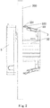
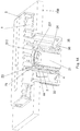
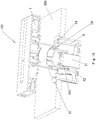
- Fig.1 is an exploded view of a fiber optic splicing assembly 100 according to an exemplary embodiment of the present invention.
- the fiber optic splicing assembly 100 may be applied to splice fibers of different optical cables according to a general invention concept.
- the fiber optic splicing assembly 100 of the present invention may be mounted to a mounting wall 200 with a mounting hole 201 (please refer to Fig.6 ).
- the fiber optic splicing assembly 100 mainly comprises a splicing panel 1 and a fiber storing device 10.
- the splicing panel 1 may be constructed as a conventional splicing panel.
- the splicing panel 1 comprises a fiber optic splicing device 11 for splicing fibers, a mounting assembly for mounting the fiber optic splicing device 11, and a storing device 12 for storing a redundant fiber.
- the fiber optic splicing assembly 100 further comprises a cover 5 covered on the splicing panel 1.
- a rear side of the splicing panel 1 is removably mounted on a front side of the mounting wall 200, and a front side of the splicing panel 1 is configured to mount the fiber optic splicing device 11 for splicing fibers.
- the fiber storing device 10 is configured to be at least partially received in the mounting hole 201, and one end of the fiber storing device 10 is removably mounted to the splicing panel 1.
- the bracket 3 comprises a support shaft 31 having a free end (please refer to Fig.9 ), and the reel 2 is movably sleeved onto the support shaft 31 so that the reel 2 can be axially moved relative to the support shaft 31 from a retraction state where the reel 2 is located in the mounting hole 201 to a expansion state where the reel 2 is exposed outside the mounting hole 201.
- the reel 2 is in the expansion state, an operator can unreel the optical cable or fiber stored on the reel 2 from an outside of the mounting wall 200.
- the reel 2 is rotatably sleeved onto the support shaft 31 and is received in the bracket 3.
- the intermediate shaft 4 is engaged to the support shaft 31 in a manner of being axially movable, and the first end (a left end shown in Fig.1 , or an upper end shown in Fig.13 ) of the intermediate shaft 4 is rotatably engaged to the reel 2.
- the intermediate shaft 4 is slidably engaged to the support shaft 31 in a profile matching manner, that is, the intermediate shaft 4 and the support shaft 31 have structures mated with each other in shape. In this way, it can prevent the intermediate shaft 4 from being rotated relative to the support shaft 31.
- the intermediate shaft 4 has a substantially tube-like structure and is slidably sleeved onto the support shaft 31. Furthermore, a plurality of slide grooves extending in the axial direction are formed in one of an inner surface of the intermediate shaft 4 and an outer surface of the support shaft 31, and a plurality of slide protrusions for being slidably fitted in respective slide grooves are formed on the other of the inner surface of the intermediate shaft 4 and the outer surface of the support shaft 31.
- the slide grooves are formed in the outer surface of the support shaft 31, and the slide protrusions are formed in the inner surface of the intermediate shaft 4 adjacent to the first end (a lower end shown in Fig.13 ).
- the intermediate shaft 4 can be slid in the axial direction with the slide protrusions fitted in the respective slide grooves of the support shaft 31, and cannot be rotated relative to the support shaft 31 because of the blocking function of the slide protrusions.
- the slide protrusions may be formed in the outer surface of the support shaft 31, and the slide grooves may be formed in the inner surface of the intermediate shaft 4 adjacent to the first end.
- the slide grooves formed in the support shaft 31 comprise at least one first slide groove 311 and at least one second slide groove 316
- the slide protrusions formed on the inner surface of the intermediate shaft 4 comprise at least one first slide protrusion 42 and at least one second slide protrusion 43.
- the first slide groove 311 is provided with a first block projection 312 at a position adjacent to the free end (a tip end) of the support shaft 31, and the second slide groove 316 is provided with a first limit projection 313 at a position adjacent to the free end of the support shaft 31.
- the first block projection 312 is locked with the first slide protrusion 42 ( Fig. 15 ) to block the intermediate shaft 4 from being disengaged from the free end of the support shaft 31, and the first limit projection 313 is snapped with the second slide protrusion 43 ( Fig. 16 ) to limit the intermediate shaft 4 from being slid in a second slide direction (a downward direction of Fig.16 ) opposite to the first slide direction.
- the first block projection 312 and the first limit projection 313 each has a matching surface substantially perpendicular to the axial direction, therefore, once the first block projection 312 is matched with the first slide protrusion 42 by sliding the intermediate shaft 4, the intermediate shaft 4 cannot be further moved forward regardless of an force exerted on it unless a matching structure of the first block projection 312 and the first slide protrusion 42 is broken. That is, the first block projection 312 is matched with the first slide protrusion 42 in a lock-fit manner.
- the first limit projection 313 and the second slide protrusion 43 each has a matching surface inclined to the axial direction, therefore, during sliding the intermediate shaft 4 from the retraction state to the expansion state, a relative large force is exerted on it in the first slide direction so that the second slide protrusion 43 can slide across the first limit projection 313 due to a flexible deformation of the second slide protrusion 43 and then position the intermediate shaft 4 in the expansion state. Thereafter, when the force is removed, the first limit projection 313 limits the second slide protrusion 43 from being moved in the second slide direction (a downward direction of Fig.16 ) opposite to the first slide direction.
- first limit projection 313 to the second slide protrusion 43 can be released and that the intermediate shaft 4 can be moved downward as shown in Fig.16 when a relative large force is exerted on the intermediate shaft 4 in the second slide direction. That is, the first limit projection 313 is matched with the second slide protrusion 43 in a snap-fit manner.
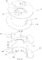
- the reel 2 comprises a cylindrical body 21 and flanges 22 formed at both ends of the cylindrical body 21.
- a notch 26 is formed in the flange 22 for the optical cable or fiber passing therethrough.
- the first end (an upper end of Figs.12 and 13 ) of the intermediate shaft 4 is engaged into the cylindrical body 21 of the reel 2 in a manner of being axially movable.
- the cylindrical body 21 is provided with a ring protrusion 24 inside a first end (a lower end of Figs. 10 and 11 ) of the cylindrical body 21, the ring protrusion 24 is rotatably fitted with the outer surface of the intermediate shaft 4 adjacent to the first end of the intermediate shaft 4.
- an engagement portion 25 is formed on and extended from the cylindrical body 21 of the reel 2 for fixing the reel 2 to the splicing panel 1 in a snap-in manner.
- a plurality of second block projections 44 are provided on the first end (an upper end in Figs. 12, 13 ) of the intermediate shaft 4, and the second block projections 44 are configured to lock with a side edge 241 of the ring protrusion 24 far away from the first end (a lower end in Figs. 10, 11 ) of the cylindrical body 21 so as to block the reel 2 from being disengaged from the first end of the intermediate shaft 4 when the reel 2 is in the expansion state.
- the second block projections 44 and the side edge 241 each has a matching surface substantially perpendicular to the axial direction.
- a plurality of second limit projections 242 are provided on the ring protrusion 24, and a ring groove 45 is formed in the outer surface of the intermediate shaft 4.
- the second limit projection 242 is snapped with the ring groove 45 so as to limit the intermediate shaft 4 from being slid in the second slide direction opposite to the first slide direction.
- a ring skirt portion 23 is provided inside a second end (an upper end in Figs. 10, 11 ) of the cylindrical body 21, and there is a gap 232 between the ring skirt portion 23 and an inner wall of the cylindrical body 21.
- the ring skirt portion 23 is located between the second end of the intermediate shaft 4 and the free end of the support shaft 31 (as shown in Fig. 14 ), so that the reel 2 can be rotated relative to the support shaft 31 and the intermediate shaft 4.
- a ring limit projection 231 is formed on the ring skirt portion 23, and a third limit projection 315 (referring to Fig.9 ) is provided on the free end of the support shaft 31.
- the ring limit projection 231 is snapped with the third limit projection 315 so as to limit the reel 2 from being moved far away from the intermediate shaft 4 when the reel 2 is in the retraction state. In this way, the reel 2 can be stably received in the bracket 3.
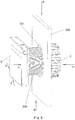
- the bracket 3 comprises a base 35 and a plurality of support arms 32.
- the support shaft 31 is supported on the base 35.
- a plurality of support arms 32 extend from an edge of the base 35.
- the bracket 3 is mounted to the mounting wall 200 by means of the support arms 32.
- a free end of the support arm 32 is provided with a flange 34 which is capable of being engaged to a front side of the mounting wall 200.
- the flange 34 is provided with a plurality of fixation pin 341 which are capable of being inserted into the mounting wall 200.
- the bracket 3 further comprises a plurality of groups of positioning devices 33 extending from an edge of the base 35, and the positioning devices 33 and the support arms 32 are arranged alternately.
- Each group of positioning devices 33 comprises a plurality of positioning elastic sheets 331 having different length with each other. Also, the positioning elastic sheet 331 is provided with a positioning projection 332.
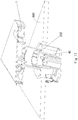
- the fiber optic splicing assembly 100 of the present invention when the fiber optic splicing assembly 100 of the present invention is mounted on the mounting wall 200, the fiber optic splicing assembly 100 is forced to pass through the mounting hole 201 from the front side of the mounting wall 200 to the rear side of the mounting wall 200, or the support arms 32 are slightly contracted inwardly to pass through the mounting hole 201 from the rear side of the mounting wall 200 to the front side of the mounting wall 200, and the flange 34 is fixed onto the front side of the mounting wall 20 with the fixation pin 341 of the flange 34.
- the positioning elastic sheets 331 of the positioning devices 33 are abut against the rear side of the mounting wall 200.
- the positioning elastic sheets 331 having a larger length are inserted into the mounting hole 201, and the positioning projections 332 of the positioning elastic sheets 331 are abut against the rear side of the mounting 200, so that the bracket 3 can be reliably mounted on the mounting wall 200.
- the support arm 32 is elastic, and a circumference formed by the support arms 32 has an outer diameter larger than a diameter of the mounting hole 201.
- the support arms 32 are mounted into the mounting hole 201, the support arms are elastically deformed and exert an elastic stress on the mounting hole 201 to fix the support arms 32 in the mounting hole 201.
- the base 35 is provided with a plurality of elastic pieces 36 inwardly protruded.
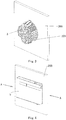
- two installation holes 14 are formed in the splicing panel 1.
- the splicing panel 1 is provided with at least two installation holes 14 for fixing the splicing panel 1 on the mounting wall 200 in cooperation with screws (not shown). After the splicing panel 1 is mounted on the mounting wall 200 by means of the installation holes 14, as shown in Figs.3-5 , by screwing the screws, the elastic pieces 36 are compressed, and the gap between the rear side of the splicing panel 1 and the front side of the mounting wall 200 can be eliminated, so that the splicing panel 1 is reliably mounted on the mounting wall 200.
Landscapes
- Physics & Mathematics (AREA)
- General Physics & Mathematics (AREA)
- Optics & Photonics (AREA)
- Engineering & Computer Science (AREA)
- Civil Engineering (AREA)
- Structural Engineering (AREA)
- Light Guides In General And Applications Therefor (AREA)
- Storage Of Web-Like Or Filamentary Materials (AREA)
Applications Claiming Priority (2)
| Application Number | Priority Date | Filing Date | Title |
|---|---|---|---|
| CN201210280488.9A CN103576266B (zh) | 2012-08-07 | 2012-08-07 | 光纤接续组件 |
| PCT/IB2013/056339 WO2014024105A1 (en) | 2012-08-07 | 2013-08-02 | Fiber optic splicing assembly |
Publications (2)
| Publication Number | Publication Date |
|---|---|
| EP2883100A1 EP2883100A1 (en) | 2015-06-17 |
| EP2883100B1 true EP2883100B1 (en) | 2019-05-01 |
Family
ID=49223832
Family Applications (1)
| Application Number | Title | Priority Date | Filing Date |
|---|---|---|---|
| EP13765517.1A Active EP2883100B1 (en) | 2012-08-07 | 2013-08-02 | Fiber optic splicing assembly |
Country Status (7)
| Country | Link |
|---|---|
| US (1) | US9594217B2 (enExample) |
| EP (1) | EP2883100B1 (enExample) |
| JP (1) | JP6313303B2 (enExample) |
| CN (2) | CN103576266B (enExample) |
| AU (1) | AU2013301184B2 (enExample) |
| NZ (1) | NZ705741A (enExample) |
| WO (1) | WO2014024105A1 (enExample) |
Families Citing this family (10)
| Publication number | Priority date | Publication date | Assignee | Title |
|---|---|---|---|---|
| WO2015067645A1 (en) | 2013-11-06 | 2015-05-14 | Adc Czech Republic, S.R.O. | Fiber termination point with overlength storage |
| US10754115B2 (en) | 2015-04-22 | 2020-08-25 | CommScope Connectivity Belgium BVBA | Deploying optical fibers within a multi-dwelling unit |
| AU2016297602B2 (en) | 2015-07-23 | 2020-12-17 | Commscope Technologies Llc | Cable spool re-orientation device for a wall box |
| US10162143B1 (en) * | 2017-09-21 | 2018-12-25 | Ofs Fitel, Llc | Behind-the-wall fiber spool module |
| DE102019106951A1 (de) * | 2019-03-19 | 2020-09-24 | Wilhelm Rutenbeck Gmbh & Co. Kg | Vorrichtung zur Aufnahme und lagesicheren Halterung von Adern eines Lichtwellenleiters |
| CN111722335B (zh) * | 2020-06-09 | 2022-09-23 | 华为技术有限公司 | 光缆收纳装置 |
| CN113566868A (zh) * | 2021-08-27 | 2021-10-29 | 国网浙江省电力有限公司信息通信分公司 | 接续盒智能监测装置 |
| WO2023097582A1 (zh) * | 2021-12-01 | 2023-06-08 | 山东微感光电子有限公司 | 一种分布式光纤测温装置、光伏板温度测量系统及方法 |
| AU2025202643A1 (en) | 2024-05-16 | 2025-12-04 | Prysmian S.P.A. | A fiber optical storage equipment |
| AU2025202638A1 (en) | 2024-05-16 | 2025-12-04 | Prysmian S.P.A. | A fiber optical storage equipment |
Family Cites Families (12)
| Publication number | Priority date | Publication date | Assignee | Title |
|---|---|---|---|---|
| US6591053B2 (en) * | 2000-03-08 | 2003-07-08 | Panduit Corp. | Fiber optic wall mount cabinet |
| JP4213367B2 (ja) * | 2001-06-20 | 2009-01-21 | 株式会社フジクラ | 光部品モジュール |
| JP2004303629A (ja) * | 2003-03-31 | 2004-10-28 | Daiwa House Ind Co Ltd | 埋込み形コンセントの構造 |
| JP2005024978A (ja) * | 2003-07-03 | 2005-01-27 | Mirai Ind Co Ltd | ケーブル引出部の構造、ケーブル引出部形成装置、巻回部材、取付枠及びプレート |
| US20080011514A1 (en) * | 2006-07-14 | 2008-01-17 | Tenvera, Inc. | Optical Fiber Distribution Apparatus and Method |
| CN101221270B (zh) * | 2007-01-13 | 2012-01-11 | 古河电子北美公司 | 可安装在墙壁上的光纤和光缆管理设备 |
| US7715679B2 (en) * | 2007-05-07 | 2010-05-11 | Adc Telecommunications, Inc. | Fiber optic enclosure with external cable spool |
| US7748660B2 (en) * | 2007-06-22 | 2010-07-06 | Ofs Fitel, Llc | Fiber optic rapid spooling tool |
| US7756379B2 (en) * | 2007-08-06 | 2010-07-13 | Adc Telecommunications, Inc. | Fiber optic enclosure with internal cable spool |
| US8265447B2 (en) * | 2008-09-16 | 2012-09-11 | Adc Telecommunications, Inc. | Modular fiber optic enclosure with external cable spool |
| CN202583564U (zh) * | 2012-05-03 | 2012-12-05 | 泰科电子(上海)有限公司 | 光纤接续盒 |
| CN202837598U (zh) * | 2012-08-07 | 2013-03-27 | 泰科电子(上海)有限公司 | 光纤接续组件 |
-
2012
- 2012-08-07 CN CN201210280488.9A patent/CN103576266B/zh not_active Expired - Fee Related
- 2012-08-07 CN CN201611163812.3A patent/CN106707434B/zh not_active Expired - Fee Related
-
2013
- 2013-08-02 AU AU2013301184A patent/AU2013301184B2/en active Active
- 2013-08-02 WO PCT/IB2013/056339 patent/WO2014024105A1/en not_active Ceased
- 2013-08-02 EP EP13765517.1A patent/EP2883100B1/en active Active
- 2013-08-02 JP JP2015525984A patent/JP6313303B2/ja active Active
- 2013-08-02 NZ NZ705741A patent/NZ705741A/en not_active IP Right Cessation
-
2015
- 2015-02-06 US US14/616,198 patent/US9594217B2/en active Active
Non-Patent Citations (1)
| Title |
|---|
| None * |
Also Published As
| Publication number | Publication date |
|---|---|
| US9594217B2 (en) | 2017-03-14 |
| WO2014024105A1 (en) | 2014-02-13 |
| NZ705741A (en) | 2017-04-28 |
| JP6313303B2 (ja) | 2018-04-18 |
| CN106707434A (zh) | 2017-05-24 |
| EP2883100A1 (en) | 2015-06-17 |
| JP2015525907A (ja) | 2015-09-07 |
| AU2013301184B2 (en) | 2016-12-22 |
| CN103576266B (zh) | 2017-01-18 |
| CN103576266A (zh) | 2014-02-12 |
| AU2013301184A1 (en) | 2015-03-26 |
| CN106707434B (zh) | 2019-06-11 |
| US20150153513A1 (en) | 2015-06-04 |
Similar Documents
| Publication | Publication Date | Title |
|---|---|---|
| EP2883100B1 (en) | Fiber optic splicing assembly | |
| USRE49385E1 (en) | Fiber optic cable distribution box | |
| US11899260B2 (en) | Fiber optic cable deployment assemblies, systems, and methods | |
| EP3286589B1 (en) | Cable storage arrangement | |
| EP2176696B1 (en) | Fiber optic enclosure with internal cable spool | |
| EP3460552B1 (en) | Behind-the-wall fiber spool module | |
| US11231557B2 (en) | Cable spool re-orientation device for a wall box | |
| EP3445694A1 (en) | Retractable fiber optic reel assembly | |
| CN202837598U (zh) | 光纤接续组件 | |
| EP4650841A1 (en) | A fiber optical storage equipment | |
| EP4650840A1 (en) | A fiber optical storage equipment | |
| HK1121238B (en) | Wall-mountable optical fiber and cable management apparatus |
Legal Events
| Date | Code | Title | Description |
|---|---|---|---|
| PUAI | Public reference made under article 153(3) epc to a published international application that has entered the european phase |
Free format text: ORIGINAL CODE: 0009012 |
|
| 17P | Request for examination filed |
Effective date: 20150309 |
|
| AK | Designated contracting states |
Kind code of ref document: A1 Designated state(s): AL AT BE BG CH CY CZ DE DK EE ES FI FR GB GR HR HU IE IS IT LI LT LU LV MC MK MT NL NO PL PT RO RS SE SI SK SM TR |
|
| AX | Request for extension of the european patent |
Extension state: BA ME |
|
| RIN1 | Information on inventor provided before grant (corrected) |
Inventor name: XIAO, TELLER Inventor name: HUBBARD, PAUL Inventor name: WANG, LIMING Inventor name: YANG, YANHONG |
|
| DAX | Request for extension of the european patent (deleted) | ||
| RAP1 | Party data changed (applicant data changed or rights of an application transferred) |
Owner name: TYCO ELECTRONICS (SHANGHAI) CO., LTD. Owner name: ADC COMMUNICATIONS (AUSTRALIA) PTY. LIMITED |
|
| RAP1 | Party data changed (applicant data changed or rights of an application transferred) |
Owner name: ADC COMMUNICATIONS (AUSTRALIA) PTY. LIMITED Owner name: ADC TELECOMMUNICATIONS (SHANGHAI) DISTRIBUTION CO. |
|
| GRAP | Despatch of communication of intention to grant a patent |
Free format text: ORIGINAL CODE: EPIDOSNIGR1 |
|
| STAA | Information on the status of an ep patent application or granted ep patent |
Free format text: STATUS: GRANT OF PATENT IS INTENDED |
|
| INTG | Intention to grant announced |
Effective date: 20180703 |
|
| GRAJ | Information related to disapproval of communication of intention to grant by the applicant or resumption of examination proceedings by the epo deleted |
Free format text: ORIGINAL CODE: EPIDOSDIGR1 |
|
| STAA | Information on the status of an ep patent application or granted ep patent |
Free format text: STATUS: REQUEST FOR EXAMINATION WAS MADE |
|
| INTC | Intention to grant announced (deleted) | ||
| GRAP | Despatch of communication of intention to grant a patent |
Free format text: ORIGINAL CODE: EPIDOSNIGR1 |
|
| STAA | Information on the status of an ep patent application or granted ep patent |
Free format text: STATUS: GRANT OF PATENT IS INTENDED |
|
| INTG | Intention to grant announced |
Effective date: 20181122 |
|
| GRAS | Grant fee paid |
Free format text: ORIGINAL CODE: EPIDOSNIGR3 |
|
| GRAA | (expected) grant |
Free format text: ORIGINAL CODE: 0009210 |
|
| STAA | Information on the status of an ep patent application or granted ep patent |
Free format text: STATUS: THE PATENT HAS BEEN GRANTED |
|
| AK | Designated contracting states |
Kind code of ref document: B1 Designated state(s): AL AT BE BG CH CY CZ DE DK EE ES FI FR GB GR HR HU IE IS IT LI LT LU LV MC MK MT NL NO PL PT RO RS SE SI SK SM TR |
|
| REG | Reference to a national code |
Ref country code: GB Ref legal event code: FG4D |
|
| REG | Reference to a national code |
Ref country code: CH Ref legal event code: EP Ref country code: AT Ref legal event code: REF Ref document number: 1127696 Country of ref document: AT Kind code of ref document: T Effective date: 20190515 |
|
| REG | Reference to a national code |
Ref country code: DE Ref legal event code: R096 Ref document number: 602013054677 Country of ref document: DE |
|
| REG | Reference to a national code |
Ref country code: IE Ref legal event code: FG4D |
|
| REG | Reference to a national code |
Ref country code: NL Ref legal event code: MP Effective date: 20190501 |
|
| REG | Reference to a national code |
Ref country code: LT Ref legal event code: MG4D |
|
| PG25 | Lapsed in a contracting state [announced via postgrant information from national office to epo] |
Ref country code: FI Free format text: LAPSE BECAUSE OF FAILURE TO SUBMIT A TRANSLATION OF THE DESCRIPTION OR TO PAY THE FEE WITHIN THE PRESCRIBED TIME-LIMIT Effective date: 20190501 Ref country code: SE Free format text: LAPSE BECAUSE OF FAILURE TO SUBMIT A TRANSLATION OF THE DESCRIPTION OR TO PAY THE FEE WITHIN THE PRESCRIBED TIME-LIMIT Effective date: 20190501 Ref country code: AL Free format text: LAPSE BECAUSE OF FAILURE TO SUBMIT A TRANSLATION OF THE DESCRIPTION OR TO PAY THE FEE WITHIN THE PRESCRIBED TIME-LIMIT Effective date: 20190501 Ref country code: NO Free format text: LAPSE BECAUSE OF FAILURE TO SUBMIT A TRANSLATION OF THE DESCRIPTION OR TO PAY THE FEE WITHIN THE PRESCRIBED TIME-LIMIT Effective date: 20190801 Ref country code: PT Free format text: LAPSE BECAUSE OF FAILURE TO SUBMIT A TRANSLATION OF THE DESCRIPTION OR TO PAY THE FEE WITHIN THE PRESCRIBED TIME-LIMIT Effective date: 20190901 Ref country code: LT Free format text: LAPSE BECAUSE OF FAILURE TO SUBMIT A TRANSLATION OF THE DESCRIPTION OR TO PAY THE FEE WITHIN THE PRESCRIBED TIME-LIMIT Effective date: 20190501 Ref country code: HR Free format text: LAPSE BECAUSE OF FAILURE TO SUBMIT A TRANSLATION OF THE DESCRIPTION OR TO PAY THE FEE WITHIN THE PRESCRIBED TIME-LIMIT Effective date: 20190501 Ref country code: ES Free format text: LAPSE BECAUSE OF FAILURE TO SUBMIT A TRANSLATION OF THE DESCRIPTION OR TO PAY THE FEE WITHIN THE PRESCRIBED TIME-LIMIT Effective date: 20190501 Ref country code: NL Free format text: LAPSE BECAUSE OF FAILURE TO SUBMIT A TRANSLATION OF THE DESCRIPTION OR TO PAY THE FEE WITHIN THE PRESCRIBED TIME-LIMIT Effective date: 20190501 |
|
| PG25 | Lapsed in a contracting state [announced via postgrant information from national office to epo] |
Ref country code: LV Free format text: LAPSE BECAUSE OF FAILURE TO SUBMIT A TRANSLATION OF THE DESCRIPTION OR TO PAY THE FEE WITHIN THE PRESCRIBED TIME-LIMIT Effective date: 20190501 Ref country code: RS Free format text: LAPSE BECAUSE OF FAILURE TO SUBMIT A TRANSLATION OF THE DESCRIPTION OR TO PAY THE FEE WITHIN THE PRESCRIBED TIME-LIMIT Effective date: 20190501 Ref country code: BG Free format text: LAPSE BECAUSE OF FAILURE TO SUBMIT A TRANSLATION OF THE DESCRIPTION OR TO PAY THE FEE WITHIN THE PRESCRIBED TIME-LIMIT Effective date: 20190801 Ref country code: GR Free format text: LAPSE BECAUSE OF FAILURE TO SUBMIT A TRANSLATION OF THE DESCRIPTION OR TO PAY THE FEE WITHIN THE PRESCRIBED TIME-LIMIT Effective date: 20190802 |
|
| REG | Reference to a national code |
Ref country code: AT Ref legal event code: MK05 Ref document number: 1127696 Country of ref document: AT Kind code of ref document: T Effective date: 20190501 |
|
| PG25 | Lapsed in a contracting state [announced via postgrant information from national office to epo] |
Ref country code: IS Free format text: LAPSE BECAUSE OF FAILURE TO SUBMIT A TRANSLATION OF THE DESCRIPTION OR TO PAY THE FEE WITHIN THE PRESCRIBED TIME-LIMIT Effective date: 20190901 |
|
| PG25 | Lapsed in a contracting state [announced via postgrant information from national office to epo] |
Ref country code: AT Free format text: LAPSE BECAUSE OF FAILURE TO SUBMIT A TRANSLATION OF THE DESCRIPTION OR TO PAY THE FEE WITHIN THE PRESCRIBED TIME-LIMIT Effective date: 20190501 Ref country code: SK Free format text: LAPSE BECAUSE OF FAILURE TO SUBMIT A TRANSLATION OF THE DESCRIPTION OR TO PAY THE FEE WITHIN THE PRESCRIBED TIME-LIMIT Effective date: 20190501 Ref country code: DK Free format text: LAPSE BECAUSE OF FAILURE TO SUBMIT A TRANSLATION OF THE DESCRIPTION OR TO PAY THE FEE WITHIN THE PRESCRIBED TIME-LIMIT Effective date: 20190501 Ref country code: EE Free format text: LAPSE BECAUSE OF FAILURE TO SUBMIT A TRANSLATION OF THE DESCRIPTION OR TO PAY THE FEE WITHIN THE PRESCRIBED TIME-LIMIT Effective date: 20190501 Ref country code: RO Free format text: LAPSE BECAUSE OF FAILURE TO SUBMIT A TRANSLATION OF THE DESCRIPTION OR TO PAY THE FEE WITHIN THE PRESCRIBED TIME-LIMIT Effective date: 20190501 Ref country code: CZ Free format text: LAPSE BECAUSE OF FAILURE TO SUBMIT A TRANSLATION OF THE DESCRIPTION OR TO PAY THE FEE WITHIN THE PRESCRIBED TIME-LIMIT Effective date: 20190501 |
|
| REG | Reference to a national code |
Ref country code: DE Ref legal event code: R097 Ref document number: 602013054677 Country of ref document: DE |
|
| PG25 | Lapsed in a contracting state [announced via postgrant information from national office to epo] |
Ref country code: SM Free format text: LAPSE BECAUSE OF FAILURE TO SUBMIT A TRANSLATION OF THE DESCRIPTION OR TO PAY THE FEE WITHIN THE PRESCRIBED TIME-LIMIT Effective date: 20190501 Ref country code: IT Free format text: LAPSE BECAUSE OF FAILURE TO SUBMIT A TRANSLATION OF THE DESCRIPTION OR TO PAY THE FEE WITHIN THE PRESCRIBED TIME-LIMIT Effective date: 20190501 |
|
| PLBE | No opposition filed within time limit |
Free format text: ORIGINAL CODE: 0009261 |
|
| STAA | Information on the status of an ep patent application or granted ep patent |
Free format text: STATUS: NO OPPOSITION FILED WITHIN TIME LIMIT |
|
| PG25 | Lapsed in a contracting state [announced via postgrant information from national office to epo] |
Ref country code: TR Free format text: LAPSE BECAUSE OF FAILURE TO SUBMIT A TRANSLATION OF THE DESCRIPTION OR TO PAY THE FEE WITHIN THE PRESCRIBED TIME-LIMIT Effective date: 20190501 |
|
| 26N | No opposition filed |
Effective date: 20200204 |
|
| PG25 | Lapsed in a contracting state [announced via postgrant information from national office to epo] |
Ref country code: PL Free format text: LAPSE BECAUSE OF FAILURE TO SUBMIT A TRANSLATION OF THE DESCRIPTION OR TO PAY THE FEE WITHIN THE PRESCRIBED TIME-LIMIT Effective date: 20190501 |
|
| PG25 | Lapsed in a contracting state [announced via postgrant information from national office to epo] |
Ref country code: SI Free format text: LAPSE BECAUSE OF FAILURE TO SUBMIT A TRANSLATION OF THE DESCRIPTION OR TO PAY THE FEE WITHIN THE PRESCRIBED TIME-LIMIT Effective date: 20190501 Ref country code: LU Free format text: LAPSE BECAUSE OF NON-PAYMENT OF DUE FEES Effective date: 20190802 Ref country code: LI Free format text: LAPSE BECAUSE OF NON-PAYMENT OF DUE FEES Effective date: 20190831 Ref country code: CH Free format text: LAPSE BECAUSE OF NON-PAYMENT OF DUE FEES Effective date: 20190831 Ref country code: MC Free format text: LAPSE BECAUSE OF FAILURE TO SUBMIT A TRANSLATION OF THE DESCRIPTION OR TO PAY THE FEE WITHIN THE PRESCRIBED TIME-LIMIT Effective date: 20190501 |
|
| REG | Reference to a national code |
Ref country code: BE Ref legal event code: MM Effective date: 20190831 |
|
| PG25 | Lapsed in a contracting state [announced via postgrant information from national office to epo] |
Ref country code: FR Free format text: LAPSE BECAUSE OF NON-PAYMENT OF DUE FEES Effective date: 20190831 Ref country code: IE Free format text: LAPSE BECAUSE OF NON-PAYMENT OF DUE FEES Effective date: 20190802 |
|
| PG25 | Lapsed in a contracting state [announced via postgrant information from national office to epo] |
Ref country code: BE Free format text: LAPSE BECAUSE OF NON-PAYMENT OF DUE FEES Effective date: 20190831 |
|
| PG25 | Lapsed in a contracting state [announced via postgrant information from national office to epo] |
Ref country code: CY Free format text: LAPSE BECAUSE OF FAILURE TO SUBMIT A TRANSLATION OF THE DESCRIPTION OR TO PAY THE FEE WITHIN THE PRESCRIBED TIME-LIMIT Effective date: 20190501 |
|
| PG25 | Lapsed in a contracting state [announced via postgrant information from national office to epo] |
Ref country code: HU Free format text: LAPSE BECAUSE OF FAILURE TO SUBMIT A TRANSLATION OF THE DESCRIPTION OR TO PAY THE FEE WITHIN THE PRESCRIBED TIME-LIMIT; INVALID AB INITIO Effective date: 20130802 Ref country code: MT Free format text: LAPSE BECAUSE OF FAILURE TO SUBMIT A TRANSLATION OF THE DESCRIPTION OR TO PAY THE FEE WITHIN THE PRESCRIBED TIME-LIMIT Effective date: 20190501 |
|
| PG25 | Lapsed in a contracting state [announced via postgrant information from national office to epo] |
Ref country code: MK Free format text: LAPSE BECAUSE OF FAILURE TO SUBMIT A TRANSLATION OF THE DESCRIPTION OR TO PAY THE FEE WITHIN THE PRESCRIBED TIME-LIMIT Effective date: 20190501 |
|
| PGFP | Annual fee paid to national office [announced via postgrant information from national office to epo] |
Ref country code: GB Payment date: 20220829 Year of fee payment: 10 |
|
| P01 | Opt-out of the competence of the unified patent court (upc) registered |
Effective date: 20230530 |
|
| GBPC | Gb: european patent ceased through non-payment of renewal fee |
Effective date: 20230802 |
|
| PG25 | Lapsed in a contracting state [announced via postgrant information from national office to epo] |
Ref country code: GB Free format text: LAPSE BECAUSE OF NON-PAYMENT OF DUE FEES Effective date: 20230802 |
|
| PG25 | Lapsed in a contracting state [announced via postgrant information from national office to epo] |
Ref country code: GB Free format text: LAPSE BECAUSE OF NON-PAYMENT OF DUE FEES Effective date: 20230802 |
|
| PGFP | Annual fee paid to national office [announced via postgrant information from national office to epo] |
Ref country code: DE Payment date: 20250827 Year of fee payment: 13 |