EP2882948B1 - Système d'entraînement d'au moins un compresseur, notamment d'un compresseur de suralimentation d'un moteur thermique - Google Patents
Système d'entraînement d'au moins un compresseur, notamment d'un compresseur de suralimentation d'un moteur thermique Download PDFInfo
- Publication number
- EP2882948B1 EP2882948B1 EP13756650.1A EP13756650A EP2882948B1 EP 2882948 B1 EP2882948 B1 EP 2882948B1 EP 13756650 A EP13756650 A EP 13756650A EP 2882948 B1 EP2882948 B1 EP 2882948B1
- Authority
- EP
- European Patent Office
- Prior art keywords
- compressor
- sun gear
- input
- configuration
- coupled
- Prior art date
- Legal status (The legal status is an assumption and is not a legal conclusion. Google has not performed a legal analysis and makes no representation as to the accuracy of the status listed.)
- Active
Links
Images


Classifications
-
- F—MECHANICAL ENGINEERING; LIGHTING; HEATING; WEAPONS; BLASTING
- F02—COMBUSTION ENGINES; HOT-GAS OR COMBUSTION-PRODUCT ENGINE PLANTS
- F02B—INTERNAL-COMBUSTION PISTON ENGINES; COMBUSTION ENGINES IN GENERAL
- F02B39/00—Component parts, details, or accessories relating to, driven charging or scavenging pumps, not provided for in groups F02B33/00 - F02B37/00
- F02B39/02—Drives of pumps; Varying pump drive gear ratio
- F02B39/04—Mechanical drives; Variable-gear-ratio drives
-
- F—MECHANICAL ENGINEERING; LIGHTING; HEATING; WEAPONS; BLASTING
- F02—COMBUSTION ENGINES; HOT-GAS OR COMBUSTION-PRODUCT ENGINE PLANTS
- F02B—INTERNAL-COMBUSTION PISTON ENGINES; COMBUSTION ENGINES IN GENERAL
- F02B37/00—Engines characterised by provision of pumps driven at least for part of the time by exhaust
- F02B37/12—Control of the pumps
-
- F—MECHANICAL ENGINEERING; LIGHTING; HEATING; WEAPONS; BLASTING
- F02—COMBUSTION ENGINES; HOT-GAS OR COMBUSTION-PRODUCT ENGINE PLANTS
- F02B—INTERNAL-COMBUSTION PISTON ENGINES; COMBUSTION ENGINES IN GENERAL
- F02B39/00—Component parts, details, or accessories relating to, driven charging or scavenging pumps, not provided for in groups F02B33/00 - F02B37/00
- F02B39/02—Drives of pumps; Varying pump drive gear ratio
- F02B39/12—Drives characterised by use of couplings or clutches therein
-
- F—MECHANICAL ENGINEERING; LIGHTING; HEATING; WEAPONS; BLASTING
- F04—POSITIVE - DISPLACEMENT MACHINES FOR LIQUIDS; PUMPS FOR LIQUIDS OR ELASTIC FLUIDS
- F04D—NON-POSITIVE-DISPLACEMENT PUMPS
- F04D25/00—Pumping installations or systems
- F04D25/02—Units comprising pumps and their driving means
- F04D25/028—Units comprising pumps and their driving means the driving means being a planetary gear
-
- Y—GENERAL TAGGING OF NEW TECHNOLOGICAL DEVELOPMENTS; GENERAL TAGGING OF CROSS-SECTIONAL TECHNOLOGIES SPANNING OVER SEVERAL SECTIONS OF THE IPC; TECHNICAL SUBJECTS COVERED BY FORMER USPC CROSS-REFERENCE ART COLLECTIONS [XRACs] AND DIGESTS
- Y02—TECHNOLOGIES OR APPLICATIONS FOR MITIGATION OR ADAPTATION AGAINST CLIMATE CHANGE
- Y02T—CLIMATE CHANGE MITIGATION TECHNOLOGIES RELATED TO TRANSPORTATION
- Y02T10/00—Road transport of goods or passengers
- Y02T10/10—Internal combustion engine [ICE] based vehicles
- Y02T10/12—Improving ICE efficiencies
Definitions
- the present invention relates to a drive system of a compressor.
- the compressor includes, but is not limited to, a supercharger compressor of a heat engine.
- the device allows the epicyclic train to alternate at least between configurations (i) and (ii) above.
- the invention makes it possible to use the outer sun gear of the epicyclic gear train which acts as a flywheel as an energy buffer. Coupling the epicyclic gear to the input of the system allows the outer sun gear to be driven by the belt and the rotating machine and to charge kinetic energy.
- the system can provide a variable reduction ratio between the rotating machine and the compressor over time through the evolution of the speed of the outer sun gear.
- the system makes it possible in particular to increase the reduction ratio provided by the system when the speed of the rotating machine increases during a transient phase following an increase in the torque setpoint of this rotating machine.
- the epicyclic train may be a type 1 train, being formed by the outer sun gear, the inner sun gear, one or more satellites, and the satellite gate.
- the inner sun gear and the outer sun gear are preferably concentric.
- the outer sun gear is connected to nothing but the satellite (s) with which it meshes, in order to form the flywheel.
- the outer sun gear is thus free to rotate.
- the coupling of the epicyclic gear to the input of the system can be done by a coupling between the planet carrier of the planetary gear train and the input of the system.
- the inner sun wheel can be movable relative to the outer sun gear.
- the first coupling member then allows to secure the inner sun gear and the outer sun gear.
- the first coupling member is for example interposed between the satellite holder and the outer sun gear of the epicyclic gear train.
- the first coupling member is interposed between the satellite carrier and the inner sun gear of the epicyclic gear train.
- the first coupling member is interposed between two elements of the epicyclic gear train, these two elements being chosen from the inner sun gear, the outer sun gear, the satellite (s) and the satellite carrier, and the first gear member. coupling allows to selectively couple these two elements.
- the satellite gate can be coupled to the input of the system while being movable relative to the inner sun wheel, which allows in particular to drive through the rotating machine the sun gear to increase the kinetic energy of the last,
- the inner sun wheel can be secured to the outer sun gear without the satellite door being coupled to the input of the system, which allows the sun gear to yield to the compressor all or part of its kinetic energy to drive the latter without taking torque from the rotating machine.
- the ratio between the output speed and the input speed of the system may vary by at least two factors.
- At least one of the first and second coupling members may be a clutch.
- the first coupling member is a clutch and the second coupling member is another clutch.
- first and / or the second coupling member may be other, for example a clutch.
- This reducer When the output of the system is connected to the compressor, a reducer can be interposed between this output and this compressor.
- This reducer has for example a reduction ratio of between ten and twenty, being for example of the order of fifteen.
- the ratio between the inertia of the outer sun gear and the inertia of the sun gear may be greater than or equal to ten, in particular being greater than twenty.
- Such a choice of value makes it possible for the external sun gear to store a satisfactory amount of kinetic energy and also, when the first coupling member is in the coupled position without the second coupling member, that the The speed of the compressor increases much faster than that of the external sun gear, favoring when the compressor is a supercharger of a heat engine supercharging and thus increasing the torque of the engine.
- the system may include a brake configured to be selectively applied to the outer sun gear of the epicyclic gear.
- a brake configured to be selectively applied to the outer sun gear of the epicyclic gear.
- the configuration (i) can be obtained by coupling the satellite door to the input of the system.
- the inner sun wheel can be movable relative to the outer sun gear.
- the configuration (ii) can be obtained by coupling the satellite door to the inner sun wheel.
- the method thus makes it possible to impose a variable ratio between the speed of the compressor and the speed of the rotating machine according to the circumstances. It is thus possible to use the drive system over a larger range.
- the satellite door can be coupled to the input of the system, so as to increase the kinetic energy of the external sun gear.
- the outer sun gear can be movable relative to the inner sun gear. This configuration of the epicyclic gear then makes it possible, by taking torque from the rotating machine, to drive the compressor while loading the external sun gear with kinetic energy.
- a threshold value which is for example equal to the above-mentioned value
- the satellite door can be coupled to the input of the system, so as to increase the kinetic energy of the external sun gear. This recovers energy that would otherwise have been dissipated.
- the speed of the rotating machine is lower than a given value, it is possible to apply a brake on the outer sun gear.
- the external sun gear is immobilized so that all the torque taken from the rotating machine by the system is used in real time to drive the compressor without loading the external sun gear with kinetic energy.
- the satellite door can be coupled to the input of the system. Also during this action of the brake, the ratio between the output speed of the system and the input speed of the system is constant.
- the configuration of the epicyclic gear train can be modified so as to transfer all or part of the energy to the compressor. kinetics of the outer sun gear.
- the method can be implemented during a transient phase following an increase in the torque setpoint of the rotating machine.
- the rotating machine may be a heat engine and the compressor may be a supercharger arranged in the intake circuit of the engine.
- the given speed value of the engine conditioning the application of the brake on the sun gear can be 1500 rpm.
- the compressor can be used in addition to a turbocharger and the drive of the compressor by the external sun gear without taking torque from the engine can both increase the pressure at the intake of the engine while ensuring a rise in turbocharger regime.
- this application of the brake may cease when the pressure on admission the engine reaches a value allowing the engine to follow the torque setpoint.
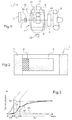
- the system 1 has an inlet 2 which is in this example connected to a belt 3 secured to a rotary machine not shown.
- the belt may have a reduction ratio of between one and three, for example equal to two.
- the rotating machine is a thermal engine of a motor vehicle.
- the engine runs for example with gasoline or diesel fuel.
- the system 1 has an output 4 which is indirectly connected to a compressor 5.
- the compressor 5 is a supercharging compressor for the engine. This includes, but is not limited to, a centrifugal compressor.
- the system 1 also comprises an epicyclic gear train 7.
- the train 7 is of type one and it comprises an inner sun gear 8, satellites 9, a satellite carrier 10 and an outer sun gear 11.
- the inner sun gear 8 is connected to the output 4 of the system while the satellite door 10 is indirectly connected to the input 2 of the system.
- the outer sun gear 11 is free, forming a flywheel.
- the ratio between the inertia of the outer sun gear 11 and that of the inner sun gear 8 is in the example considered greater than ten, or even twenty.
- the system 1 further comprises a device 15 making it possible to modify the configuration of the epicyclic gear train 7.
- This device 15 is in the example described in the form of two coupling members 20 and 21 which are notably clutches.
- the second coupling member 20 is interposed between the input 2 of the system 1 and the satellite carrier 10 and selectively couples the input 2 to the satellite carrier 10.
- the first coupling member 21 is in the example considered interposed between the satellite carrier 10 and the inner sun gear 8 and selectively couples the satellite carrier 10 and the inner sun gear 8, so as to eliminate any internal degree of freedom of the planetary gear train 7.
- an additional gearbox 24 can be arranged between the outlet 4 of the system 1 and the compressor 5.
- the ratio between the output speed of the system 1 and the input speed 2 of the system 1 varies, for example, between one and three, whereas when the epicyclic gear train 7 is in the configuration (ii), the whole epicyclic gear train 7 rotates at the same speed.
- the system 1 may also comprise a brake 26, represented very schematically on the figure 1 , able to come to apply against the outer sun gear 11, as will be seen later.
- the rotating machine is a motor vehicle engine.
- the engine includes an intake circuit and a circuit exhaust and the compressor 5 is a supercharger arranged in the engine intake circuit in addition to the turbocharger.
- the exhaust circuit further comprises in the application described a valve called wastegate allowing, according to its position, all or part of the exhaust gas to bypass the turbine of the turbocharger.
- the Figures 3 to 5 relate to the use of the system 1 to drive the compressor 5 following an increase in the torque setpoint of the engine in three different situations.
- the curve 30 represents the pressure ratio of the compressor, that is to say the quotient between the outlet pressure and the inlet pressure of the compressor 5
- the curve 31 represents the pressure ratio of the turbocharger
- the curve 32 represents the total pressure ratio, that is to say the product of the pressure ratio of the compressor 5 and the turbocharger
- the curve 33 represents the pressure ratio that would be obtained in the absence of the compressor 5 and the system 1.
- the device 15 is actuated so that the planetary gear train 7 is in the configuration (i) above, that is to say that the satellite carrier 10 is coupled to the input 2 of the system 1 without being coupled to the inner sun wheel 8.
- This configuration (i) occurs during a phase 40 shown on the figure 3 .
- the belt 3 drives the satellite gate 10 whose movement is transmitted to the satellites 9, and the latter meshing with the inner sun gear 8 and the outer sun gear 11, the speed of the compressor 5 and the speed of the outer sun gear 11 increase.
- the increase in pressure in the intake circuit is almost exclusively due to the compressor 5.
- the speed of the latter increases less quickly than the speed of the compressor 5, this increase in the speed of the outer sun gear 11 leading to a reduction in the ratio between the speed of the inner sun gear 8 and that of the satellite gate 10, that is to say between the output speed of the system 1 and the input speed of the system 1.
- the outer sun gear 11 being free to rotate, its speed increases gradually during this phase 40 and the outer sun gear 11 can then be loaded with kinetic energy thanks to the torque taken from the engine .
- the device 15 When the speed of the outer sun gear 11 becomes equal to that of the inner sun gear 8, the device 15 is actuated so that the epicyclic gear train 7 passes from the configuration (i) to the configuration (ii) in which the satellite carrier 10 is coupled to the inner sun gear 8 without being coupled to the input 2 of the system 1. According to this configuration, the epicyclic gear 7 rotates en bloc.
- phase 41 The transition to this configuration (ii) corresponds to the beginning of a phase 41.
- this phase 41 no torque is taken from the heat engine and the drive of the compressor 5 is obtained by transferring the external sun gear 11 to the compressor 5 of all or part of the kinetic energy stored in the outer sun gear 11 during phase 40.
- phase 41 the turbocharger rises in revolutions, this revving being particularly favored by the fact that the compressor 5 allowed a rise in supercharging pressure faster therefore an increase in the energy of the exhaust gases which drive the turbine of the turbocharger.
- Phase 41 ends when the inlet pressure of the engine reaches the value allowing the motor to follow the torque setpoint. As shown on the figure 3 when this pressure value is reached, kinetic energy can still be present in the outer sun gear 11, so that the latter continues to drive the compressor 5.
- a braking phase precedes the increase in the torque setpoint and, during this braking phase, the device 15 is actuated so that the epicyclic gear train 7 is in the configuration (i).
- the belt 3 drives the satellite gate 10 whose movement is transmitted to the satellites 9, and the latter meshing with the inner sun gear 8 and the outer sun gear 11, the speed of the compressor 5 and the speed of the outer sun gear. 11 increase.
- Kinetic energy is thus stored in the outer sun gear 11.
- a throttle valve in the engine intake circuit downstream of the compressor can close, so that the compressor 5 provides a resistant torque. increasing the speed of the outer sun gear 11 and thus the amount of kinetic energy stored therein.
- the device 15 can be actuated so that the epicyclic gear train goes to configuration (ii).
- the behavior of the compressor 5 will then be described with reference to the figure 4 .
- a first phase 45 corresponds to the closing of the first coupling member 21. As shown, during this phase 45, the inlet pressure of the engine is almost exclusively provided by the compressor 5.
- Phase 45 ends when train 7 is in configuration (ii) and phases 46 and 47 are similar to those described with reference to FIG. figure 3 can then successively occur.
- the phase 50 corresponds to the action on the device 15 so that the epicyclic train takes the configuration (i) while the brake 26 is already applied to the outer sun gear 11.
- the ratio of The total pressure, from which the intake pressure of the engine is derived increases sharply, being almost identical to the pressure ratio of the compressor 5.
- Phase 51 follows phase 50 when train 7 is in configuration (i). During this phase 51, the compressor 5 operates at constant speed, as can be seen on the figure 5 .
- the constant value of the ratio between the output speed of the system 1 and the input speed of the system 1 during this phase 51 is, for example, strictly greater than two, in particular being between 2.5 and 3.5
- phase 51 ends when the intake pressure of the engine takes a value allowing the engine to follow the torque setpoint.
- the brake 26 is then released, so that, during a subsequent phase 52, the outer sun gear 11 can be rotated and store kinetic energy while the turbocharger rises rapidly under pressure.
- phase 52 the ratio between the output speed of the system 1 and the input speed of the system 1 decreases from the value it had at the end of the phase 51 to reach one.
- This phase 52 ends when the outer sun gear 11 and the inner sun gear 8 have the same speed.
- the device 15 is then acted on so that the planetary gear train 7 takes the configuration (ii) in which the drive of the compressor 5 is effected by virtue of the energy kinetic previously stored in the outer sun gear 11, without taking torque from the engine. If necessary, this phase 52 may be followed by a subsequent phase similar to the phases 42 or 47 described with reference to the figures 3 and 4 .
- the curve 60 corresponds to the speed of the inner sun wheel 8 while the curve 61 corresponds to the speed of the outer sun gear 11 in rpm.
- the curve 65 corresponds to the mechanical energy of the compressor 5.
- curve 66 corresponds to the speed of satellite gate 10.
- the compressor may be other than a centrifugal compressor, for example a compressor called "roots" or a scroll compressor.
Landscapes
- Engineering & Computer Science (AREA)
- Mechanical Engineering (AREA)
- General Engineering & Computer Science (AREA)
- Chemical & Material Sciences (AREA)
- Combustion & Propulsion (AREA)
- Supercharger (AREA)
- Compressors, Vaccum Pumps And Other Relevant Systems (AREA)
Priority Applications (1)
| Application Number | Priority Date | Filing Date | Title |
|---|---|---|---|
| PL13756650T PL2882948T3 (pl) | 2012-08-13 | 2013-08-01 | Układ napędowy co najmniej jednej sprężarki, zwłaszcza sprężarki doładowania silnika cieplnego |
Applications Claiming Priority (2)
| Application Number | Priority Date | Filing Date | Title |
|---|---|---|---|
| FR1257788A FR2994457B1 (fr) | 2012-08-13 | 2012-08-13 | Systeme d'entrainement d'au moins un compresseur, notamment d'un compresseur de suralimentation d'un moteur thermique |
| PCT/FR2013/051866 WO2014027156A1 (fr) | 2012-08-13 | 2013-08-01 | Système d'entraînement d'au moins un compresseur, notamment d'un compresseur de suralimentation d'un moteur thermique |
Publications (2)
| Publication Number | Publication Date |
|---|---|
| EP2882948A1 EP2882948A1 (fr) | 2015-06-17 |
| EP2882948B1 true EP2882948B1 (fr) | 2016-09-07 |
Family
ID=46852308
Family Applications (1)
| Application Number | Title | Priority Date | Filing Date |
|---|---|---|---|
| EP13756650.1A Active EP2882948B1 (fr) | 2012-08-13 | 2013-08-01 | Système d'entraînement d'au moins un compresseur, notamment d'un compresseur de suralimentation d'un moteur thermique |
Country Status (6)
| Country | Link |
|---|---|
| US (1) | US9664105B2 (pl) |
| EP (1) | EP2882948B1 (pl) |
| JP (1) | JP6165863B2 (pl) |
| FR (1) | FR2994457B1 (pl) |
| PL (1) | PL2882948T3 (pl) |
| WO (1) | WO2014027156A1 (pl) |
Families Citing this family (2)
| Publication number | Priority date | Publication date | Assignee | Title |
|---|---|---|---|---|
| GB2521657B (en) * | 2013-12-27 | 2020-08-19 | Valeo Air Man Uk Limited | Control of a motor in an electric supercharger |
| US10662903B2 (en) * | 2015-02-27 | 2020-05-26 | Avl Powertrain Engineering, Inc. | Waste heat recovery and boost systems including variable drive mechanisms |
Family Cites Families (25)
| Publication number | Priority date | Publication date | Assignee | Title |
|---|---|---|---|---|
| US2390626A (en) * | 1942-11-18 | 1945-12-11 | Szekely Company Inc | Aircraft supercharger drive |
| US2585029A (en) * | 1947-10-23 | 1952-02-12 | Nettel Frederick | Self-powered turbosupercharger starter system for internalcombustion engines |
| US2929198A (en) * | 1957-02-04 | 1960-03-22 | Crocchi Piero | Drive system |
| US3007302A (en) * | 1958-09-30 | 1961-11-07 | Continental Aviat & Eng Corp | Compound turbine-diesel power plant |
| US3307426A (en) * | 1960-01-11 | 1967-03-07 | Garrett Corp | Constant speed drive starter |
| JPS595832A (ja) * | 1982-06-30 | 1984-01-12 | Diesel Kiki Co Ltd | タ−ボチヤ−ジヤ機構 |
| DE3311310C1 (de) * | 1983-03-28 | 1984-06-20 | Bhs Bayerische Berg | Planetengetriebe,das zwischen einer Stroemungsmaschine und einer elektrischen Maschine in einem Gehaeuse angeordnet ist |
| JPS6112943U (ja) * | 1984-06-29 | 1986-01-25 | 株式会社小松製作所 | 過給エンジン |
| DE3832288A1 (de) * | 1988-09-22 | 1990-04-05 | Hurth Masch Zahnrad Carl | Reibungskupplung |
| US4989410A (en) * | 1989-04-03 | 1991-02-05 | Smith Roger R | Compound power plant |
| JPH08210144A (ja) * | 1991-11-25 | 1996-08-20 | Kanesaka Gijutsu Kenkyusho:Kk | ターボチャージャーと差動駆動過給機とを備えたエンジン |
| GB2317647B (en) * | 1994-01-25 | 1998-09-30 | Komatsu Mfg Co Ltd | A method of controlling a mechanical supercharger |
| JP3547735B2 (ja) * | 2001-11-22 | 2004-07-28 | 本田技研工業株式会社 | エンジンシステムとその運転方法およびエンジン始動装置 |
| JP2004360487A (ja) * | 2003-06-02 | 2004-12-24 | Honda Motor Co Ltd | 遊星歯車機構を備えた過給機 |
| DE102004018420B4 (de) * | 2004-04-08 | 2014-10-30 | Volkswagen Ag | Mechanischer Lader mit Umlaufgetriebeantrieb |
| US20070137626A1 (en) * | 2005-12-21 | 2007-06-21 | David Turner | Engine supercharging system |
| ATE528494T1 (de) * | 2006-08-23 | 2011-10-15 | Timken Co | Superverdichter mit variabler geschwindigkeit und erzeugung elektrischer energie |
| DE102007007037A1 (de) * | 2007-02-08 | 2008-08-14 | Iav Gmbh Ingenieurgesellschaft Auto Und Verkehr | Planetengetriebe |
| GB0708835D0 (en) * | 2007-05-08 | 2007-06-13 | Nexxtdrive Ltd | Automotive air blowers |
| US7765805B2 (en) * | 2007-07-24 | 2010-08-03 | Kasi Forvaltning I Goteborg Ab | Enhanced supercharging system and an internal combustion engine having such a system |
| US8196686B2 (en) * | 2008-12-18 | 2012-06-12 | Delphi Technologies, Inc. | Supercharged hybrid input differential engine system |
| WO2011127389A2 (en) * | 2010-04-08 | 2011-10-13 | The Regents Of The University Of Colorado | Hybrid transmission using planetary gearset for multiple sources of torque for marine, two wheel land, or aeronautical vehicles |
| US8701636B2 (en) * | 2011-04-28 | 2014-04-22 | Caterpillar Inc. | Variable input driving system and method |
| KR101338081B1 (ko) * | 2012-03-27 | 2014-02-12 | 현대자동차주식회사 | 엔진의 플라이휠 |
| US8795133B2 (en) * | 2012-11-01 | 2014-08-05 | Caterpillar Inc. | Event-based retarding in a machine with a continuously variable transmission |
-
2012
- 2012-08-13 FR FR1257788A patent/FR2994457B1/fr active Active
-
2013
- 2013-08-01 US US14/420,786 patent/US9664105B2/en active Active
- 2013-08-01 PL PL13756650T patent/PL2882948T3/pl unknown
- 2013-08-01 WO PCT/FR2013/051866 patent/WO2014027156A1/fr not_active Ceased
- 2013-08-01 JP JP2015527014A patent/JP6165863B2/ja active Active
- 2013-08-01 EP EP13756650.1A patent/EP2882948B1/fr active Active
Also Published As
| Publication number | Publication date |
|---|---|
| JP2015530511A (ja) | 2015-10-15 |
| FR2994457B1 (fr) | 2014-08-08 |
| US20150233284A1 (en) | 2015-08-20 |
| WO2014027156A1 (fr) | 2014-02-20 |
| JP6165863B2 (ja) | 2017-07-19 |
| FR2994457A1 (fr) | 2014-02-14 |
| PL2882948T3 (pl) | 2017-07-31 |
| EP2882948A1 (fr) | 2015-06-17 |
| US9664105B2 (en) | 2017-05-30 |
Similar Documents
| Publication | Publication Date | Title |
|---|---|---|
| FR2782959A1 (fr) | Train d'entrainement pour un vehicule automobile,comportant un moteur electrique utilise comme moteur et comme generateur. | |
| FR2797230A1 (fr) | Chaine motrice | |
| EP0683874B1 (fr) | Transmission avec dispositif de demarrage progressif, en particulier pour vehicule | |
| EP0683877B1 (fr) | Dispositif de transmission, en particulier pour vehicule, et procedes de pilotage s'y rapportant | |
| WO2014027156A1 (fr) | Système d'entraînement d'au moins un compresseur, notamment d'un compresseur de suralimentation d'un moteur thermique | |
| WO2013083885A1 (fr) | Dispositif de transmission, groupe motopropulseur, accumulateur d'energie, et vehicule ainsi equipe | |
| FR2781265A1 (fr) | Embrayage a friction auto-renforcant | |
| FR2885649A1 (fr) | Systeme de suralimentation pour moteur a allumage par compression | |
| FR2787141A1 (fr) | Moteur a combustion interne suralimente | |
| EP3390797B1 (fr) | Procédé de pilotage d'un moteur à combustion interne suralimenté et moteur suralimenté associé | |
| EP1797357B1 (fr) | Dispositif de transmission pour auxiliaire ou accessoire de moteur a vitesse variable, moteur ainsi equipe et applications | |
| JP6642190B2 (ja) | 内燃機関システム | |
| EP3751112B1 (fr) | Procédé de pilotage d'un ensemble comportant un turbocompresseur et des moyens complémentaires d' entraînement | |
| FR2748781A1 (fr) | Procede et dispositif pour entrainer une pompe de carburant | |
| FR2937088A1 (fr) | Distributeur de fluide dans une turbomachine | |
| FR3019234A1 (fr) | Lanceur de demarreur muni d'un couvercle limitant l'usure | |
| FR3045762A1 (fr) | Chaine de transmission mecanique entre un demarreur/generateur et une turbomachine d'aeronef, ensemble et procede associe | |
| EP3985243A1 (fr) | Dispositif de traction et/ou de propulsion de véhicule comprenant un moyen de conversion de couple | |
| FR2986747A1 (fr) | Dispositif de transmission, groupe motopropulseur, accumulateur d'energie, et vehicule ainsi equipe | |
| FR2971550A1 (fr) | Dispositif de transmission de puissance integrant un convertisseur de couple et procede de pilotage d'un tel dispositif | |
| FR2876151A1 (fr) | Moteur comportant un compresseur entraine selectivement par une turbine ou par le vilebrequin du moteur | |
| FR3127030A1 (fr) | Ensemble de suralimentation de gaz | |
| WO2020083922A1 (fr) | Procédé et système de contrôle d'un régime moteur de véhicule | |
| FR3007073A1 (fr) | Procede de pilotage d'un moteur a combustion interne suralimente et moteur suralimente associe | |
| FR2983547A1 (fr) | Dispositif de transmission, groupe motopropulseur, accumulateur d'energie, et vehicule ainsi equipe |
Legal Events
| Date | Code | Title | Description |
|---|---|---|---|
| PUAI | Public reference made under article 153(3) epc to a published international application that has entered the european phase |
Free format text: ORIGINAL CODE: 0009012 |
|
| 17P | Request for examination filed |
Effective date: 20150129 |
|
| AK | Designated contracting states |
Kind code of ref document: A1 Designated state(s): AL AT BE BG CH CY CZ DE DK EE ES FI FR GB GR HR HU IE IS IT LI LT LU LV MC MK MT NL NO PL PT RO RS SE SI SK SM TR |
|
| AX | Request for extension of the european patent |
Extension state: BA ME |
|
| RIN1 | Information on inventor provided before grant (corrected) |
Inventor name: ALFANO, DAMIEN Inventor name: LAGRE, JEAN-LOUIS |
|
| DAX | Request for extension of the european patent (deleted) | ||
| GRAP | Despatch of communication of intention to grant a patent |
Free format text: ORIGINAL CODE: EPIDOSNIGR1 |
|
| INTG | Intention to grant announced |
Effective date: 20160311 |
|
| GRAS | Grant fee paid |
Free format text: ORIGINAL CODE: EPIDOSNIGR3 |
|
| GRAA | (expected) grant |
Free format text: ORIGINAL CODE: 0009210 |
|
| AK | Designated contracting states |
Kind code of ref document: B1 Designated state(s): AL AT BE BG CH CY CZ DE DK EE ES FI FR GB GR HR HU IE IS IT LI LT LU LV MC MK MT NL NO PL PT RO RS SE SI SK SM TR |
|
| REG | Reference to a national code |
Ref country code: GB Ref legal event code: FG4D Free format text: NOT ENGLISH |
|
| REG | Reference to a national code |
Ref country code: CH Ref legal event code: EP |
|
| REG | Reference to a national code |
Ref country code: IE Ref legal event code: FG4D Free format text: LANGUAGE OF EP DOCUMENT: FRENCH |
|
| REG | Reference to a national code |
Ref country code: AT Ref legal event code: REF Ref document number: 827093 Country of ref document: AT Kind code of ref document: T Effective date: 20161015 |
|
| REG | Reference to a national code |
Ref country code: DE Ref legal event code: R096 Ref document number: 602013011183 Country of ref document: DE |
|
| REG | Reference to a national code |
Ref country code: LT Ref legal event code: MG4D |
|
| REG | Reference to a national code |
Ref country code: NL Ref legal event code: MP Effective date: 20160907 |
|
| PG25 | Lapsed in a contracting state [announced via postgrant information from national office to epo] |
Ref country code: NO Free format text: LAPSE BECAUSE OF FAILURE TO SUBMIT A TRANSLATION OF THE DESCRIPTION OR TO PAY THE FEE WITHIN THE PRESCRIBED TIME-LIMIT Effective date: 20161207 Ref country code: RS Free format text: LAPSE BECAUSE OF FAILURE TO SUBMIT A TRANSLATION OF THE DESCRIPTION OR TO PAY THE FEE WITHIN THE PRESCRIBED TIME-LIMIT Effective date: 20160907 Ref country code: HR Free format text: LAPSE BECAUSE OF FAILURE TO SUBMIT A TRANSLATION OF THE DESCRIPTION OR TO PAY THE FEE WITHIN THE PRESCRIBED TIME-LIMIT Effective date: 20160907 Ref country code: FI Free format text: LAPSE BECAUSE OF FAILURE TO SUBMIT A TRANSLATION OF THE DESCRIPTION OR TO PAY THE FEE WITHIN THE PRESCRIBED TIME-LIMIT Effective date: 20160907 Ref country code: LT Free format text: LAPSE BECAUSE OF FAILURE TO SUBMIT A TRANSLATION OF THE DESCRIPTION OR TO PAY THE FEE WITHIN THE PRESCRIBED TIME-LIMIT Effective date: 20160907 |
|
| REG | Reference to a national code |
Ref country code: AT Ref legal event code: MK05 Ref document number: 827093 Country of ref document: AT Kind code of ref document: T Effective date: 20160907 |
|
| PG25 | Lapsed in a contracting state [announced via postgrant information from national office to epo] |
Ref country code: ES Free format text: LAPSE BECAUSE OF FAILURE TO SUBMIT A TRANSLATION OF THE DESCRIPTION OR TO PAY THE FEE WITHIN THE PRESCRIBED TIME-LIMIT Effective date: 20160907 Ref country code: LV Free format text: LAPSE BECAUSE OF FAILURE TO SUBMIT A TRANSLATION OF THE DESCRIPTION OR TO PAY THE FEE WITHIN THE PRESCRIBED TIME-LIMIT Effective date: 20160907 Ref country code: NL Free format text: LAPSE BECAUSE OF FAILURE TO SUBMIT A TRANSLATION OF THE DESCRIPTION OR TO PAY THE FEE WITHIN THE PRESCRIBED TIME-LIMIT Effective date: 20160907 Ref country code: GR Free format text: LAPSE BECAUSE OF FAILURE TO SUBMIT A TRANSLATION OF THE DESCRIPTION OR TO PAY THE FEE WITHIN THE PRESCRIBED TIME-LIMIT Effective date: 20161208 Ref country code: SE Free format text: LAPSE BECAUSE OF FAILURE TO SUBMIT A TRANSLATION OF THE DESCRIPTION OR TO PAY THE FEE WITHIN THE PRESCRIBED TIME-LIMIT Effective date: 20160907 |
|
| PG25 | Lapsed in a contracting state [announced via postgrant information from national office to epo] |
Ref country code: EE Free format text: LAPSE BECAUSE OF FAILURE TO SUBMIT A TRANSLATION OF THE DESCRIPTION OR TO PAY THE FEE WITHIN THE PRESCRIBED TIME-LIMIT Effective date: 20160907 Ref country code: RO Free format text: LAPSE BECAUSE OF FAILURE TO SUBMIT A TRANSLATION OF THE DESCRIPTION OR TO PAY THE FEE WITHIN THE PRESCRIBED TIME-LIMIT Effective date: 20160907 |
|
| PG25 | Lapsed in a contracting state [announced via postgrant information from national office to epo] |
Ref country code: CZ Free format text: LAPSE BECAUSE OF FAILURE TO SUBMIT A TRANSLATION OF THE DESCRIPTION OR TO PAY THE FEE WITHIN THE PRESCRIBED TIME-LIMIT Effective date: 20160907 Ref country code: SM Free format text: LAPSE BECAUSE OF FAILURE TO SUBMIT A TRANSLATION OF THE DESCRIPTION OR TO PAY THE FEE WITHIN THE PRESCRIBED TIME-LIMIT Effective date: 20160907 Ref country code: SK Free format text: LAPSE BECAUSE OF FAILURE TO SUBMIT A TRANSLATION OF THE DESCRIPTION OR TO PAY THE FEE WITHIN THE PRESCRIBED TIME-LIMIT Effective date: 20160907 Ref country code: AT Free format text: LAPSE BECAUSE OF FAILURE TO SUBMIT A TRANSLATION OF THE DESCRIPTION OR TO PAY THE FEE WITHIN THE PRESCRIBED TIME-LIMIT Effective date: 20160907 Ref country code: IS Free format text: LAPSE BECAUSE OF FAILURE TO SUBMIT A TRANSLATION OF THE DESCRIPTION OR TO PAY THE FEE WITHIN THE PRESCRIBED TIME-LIMIT Effective date: 20170107 Ref country code: PT Free format text: LAPSE BECAUSE OF FAILURE TO SUBMIT A TRANSLATION OF THE DESCRIPTION OR TO PAY THE FEE WITHIN THE PRESCRIBED TIME-LIMIT Effective date: 20170109 Ref country code: BG Free format text: LAPSE BECAUSE OF FAILURE TO SUBMIT A TRANSLATION OF THE DESCRIPTION OR TO PAY THE FEE WITHIN THE PRESCRIBED TIME-LIMIT Effective date: 20161207 |
|
| REG | Reference to a national code |
Ref country code: DE Ref legal event code: R097 Ref document number: 602013011183 Country of ref document: DE |
|
| PG25 | Lapsed in a contracting state [announced via postgrant information from national office to epo] |
Ref country code: IT Free format text: LAPSE BECAUSE OF FAILURE TO SUBMIT A TRANSLATION OF THE DESCRIPTION OR TO PAY THE FEE WITHIN THE PRESCRIBED TIME-LIMIT Effective date: 20160907 |
|
| PLBE | No opposition filed within time limit |
Free format text: ORIGINAL CODE: 0009261 |
|
| STAA | Information on the status of an ep patent application or granted ep patent |
Free format text: STATUS: NO OPPOSITION FILED WITHIN TIME LIMIT |
|
| PG25 | Lapsed in a contracting state [announced via postgrant information from national office to epo] |
Ref country code: DK Free format text: LAPSE BECAUSE OF FAILURE TO SUBMIT A TRANSLATION OF THE DESCRIPTION OR TO PAY THE FEE WITHIN THE PRESCRIBED TIME-LIMIT Effective date: 20160907 |
|
| 26N | No opposition filed |
Effective date: 20170608 |
|
| PG25 | Lapsed in a contracting state [announced via postgrant information from national office to epo] |
Ref country code: SI Free format text: LAPSE BECAUSE OF FAILURE TO SUBMIT A TRANSLATION OF THE DESCRIPTION OR TO PAY THE FEE WITHIN THE PRESCRIBED TIME-LIMIT Effective date: 20160907 |
|
| REG | Reference to a national code |
Ref country code: FR Ref legal event code: PLFP Year of fee payment: 5 |
|
| REG | Reference to a national code |
Ref country code: CH Ref legal event code: PL |
|
| PG25 | Lapsed in a contracting state [announced via postgrant information from national office to epo] |
Ref country code: MC Free format text: LAPSE BECAUSE OF FAILURE TO SUBMIT A TRANSLATION OF THE DESCRIPTION OR TO PAY THE FEE WITHIN THE PRESCRIBED TIME-LIMIT Effective date: 20160907 |
|
| PG25 | Lapsed in a contracting state [announced via postgrant information from national office to epo] |
Ref country code: LI Free format text: LAPSE BECAUSE OF NON-PAYMENT OF DUE FEES Effective date: 20170831 Ref country code: CH Free format text: LAPSE BECAUSE OF NON-PAYMENT OF DUE FEES Effective date: 20170831 |
|
| REG | Reference to a national code |
Ref country code: IE Ref legal event code: MM4A |
|
| REG | Reference to a national code |
Ref country code: BE Ref legal event code: MM Effective date: 20170831 |
|
| PG25 | Lapsed in a contracting state [announced via postgrant information from national office to epo] |
Ref country code: LU Free format text: LAPSE BECAUSE OF NON-PAYMENT OF DUE FEES Effective date: 20170801 |
|
| PG25 | Lapsed in a contracting state [announced via postgrant information from national office to epo] |
Ref country code: IE Free format text: LAPSE BECAUSE OF NON-PAYMENT OF DUE FEES Effective date: 20170801 |
|
| REG | Reference to a national code |
Ref country code: FR Ref legal event code: PLFP Year of fee payment: 6 |
|
| PG25 | Lapsed in a contracting state [announced via postgrant information from national office to epo] |
Ref country code: BE Free format text: LAPSE BECAUSE OF NON-PAYMENT OF DUE FEES Effective date: 20170831 |
|
| PG25 | Lapsed in a contracting state [announced via postgrant information from national office to epo] |
Ref country code: MT Free format text: LAPSE BECAUSE OF FAILURE TO SUBMIT A TRANSLATION OF THE DESCRIPTION OR TO PAY THE FEE WITHIN THE PRESCRIBED TIME-LIMIT Effective date: 20160907 |
|
| PG25 | Lapsed in a contracting state [announced via postgrant information from national office to epo] |
Ref country code: AL Free format text: LAPSE BECAUSE OF FAILURE TO SUBMIT A TRANSLATION OF THE DESCRIPTION OR TO PAY THE FEE WITHIN THE PRESCRIBED TIME-LIMIT Effective date: 20160907 |
|
| PG25 | Lapsed in a contracting state [announced via postgrant information from national office to epo] |
Ref country code: HU Free format text: LAPSE BECAUSE OF FAILURE TO SUBMIT A TRANSLATION OF THE DESCRIPTION OR TO PAY THE FEE WITHIN THE PRESCRIBED TIME-LIMIT; INVALID AB INITIO Effective date: 20130801 |
|
| PG25 | Lapsed in a contracting state [announced via postgrant information from national office to epo] |
Ref country code: CY Free format text: LAPSE BECAUSE OF FAILURE TO SUBMIT A TRANSLATION OF THE DESCRIPTION OR TO PAY THE FEE WITHIN THE PRESCRIBED TIME-LIMIT Effective date: 20160907 |
|
| PG25 | Lapsed in a contracting state [announced via postgrant information from national office to epo] |
Ref country code: MK Free format text: LAPSE BECAUSE OF FAILURE TO SUBMIT A TRANSLATION OF THE DESCRIPTION OR TO PAY THE FEE WITHIN THE PRESCRIBED TIME-LIMIT Effective date: 20160907 |
|
| PG25 | Lapsed in a contracting state [announced via postgrant information from national office to epo] |
Ref country code: TR Free format text: LAPSE BECAUSE OF FAILURE TO SUBMIT A TRANSLATION OF THE DESCRIPTION OR TO PAY THE FEE WITHIN THE PRESCRIBED TIME-LIMIT Effective date: 20160907 |
|
| P01 | Opt-out of the competence of the unified patent court (upc) registered |
Effective date: 20230528 |
|
| PGFP | Annual fee paid to national office [announced via postgrant information from national office to epo] |
Ref country code: DE Payment date: 20250812 Year of fee payment: 13 |
|
| PGFP | Annual fee paid to national office [announced via postgrant information from national office to epo] |
Ref country code: PL Payment date: 20250722 Year of fee payment: 13 |
|
| PGFP | Annual fee paid to national office [announced via postgrant information from national office to epo] |
Ref country code: GB Payment date: 20250826 Year of fee payment: 13 |
|
| PGFP | Annual fee paid to national office [announced via postgrant information from national office to epo] |
Ref country code: FR Payment date: 20250828 Year of fee payment: 13 |