EP2882487B1 - Connecteur a usage médical - Google Patents
Connecteur a usage médical Download PDFInfo
- Publication number
- EP2882487B1 EP2882487B1 EP13758956.0A EP13758956A EP2882487B1 EP 2882487 B1 EP2882487 B1 EP 2882487B1 EP 13758956 A EP13758956 A EP 13758956A EP 2882487 B1 EP2882487 B1 EP 2882487B1
- Authority
- EP
- European Patent Office
- Prior art keywords
- connector
- chamber
- elastic seal
- seal
- ring
- Prior art date
- Legal status (The legal status is an assumption and is not a legal conclusion. Google has not performed a legal analysis and makes no representation as to the accuracy of the status listed.)
- Active
Links
- 230000002093 peripheral effect Effects 0.000 claims description 33
- 238000011144 upstream manufacturing Methods 0.000 claims description 9
- 239000011324 bead Substances 0.000 claims description 4
- 238000011109 contamination Methods 0.000 description 11
- 239000012530 fluid Substances 0.000 description 10
- 239000000463 material Substances 0.000 description 7
- 238000007789 sealing Methods 0.000 description 6
- 238000005070 sampling Methods 0.000 description 5
- 230000000694 effects Effects 0.000 description 4
- 230000001580 bacterial effect Effects 0.000 description 3
- 239000007788 liquid Substances 0.000 description 3
- 210000004027 cell Anatomy 0.000 description 2
- 230000008878 coupling Effects 0.000 description 2
- 238000010168 coupling process Methods 0.000 description 2
- 238000005859 coupling reaction Methods 0.000 description 2
- 230000014509 gene expression Effects 0.000 description 2
- 244000144725 Amygdalus communis Species 0.000 description 1
- 241000894006 Bacteria Species 0.000 description 1
- 240000008042 Zea mays Species 0.000 description 1
- 238000004026 adhesive bonding Methods 0.000 description 1
- 235000020224 almond Nutrition 0.000 description 1
- 230000005540 biological transmission Effects 0.000 description 1
- 239000002131 composite material Substances 0.000 description 1
- 230000006835 compression Effects 0.000 description 1
- 238000007906 compression Methods 0.000 description 1
- 239000000470 constituent Substances 0.000 description 1
- 238000005202 decontamination Methods 0.000 description 1
- 230000003588 decontaminative effect Effects 0.000 description 1
- 239000013013 elastic material Substances 0.000 description 1
- 238000002347 injection Methods 0.000 description 1
- 239000007924 injection Substances 0.000 description 1
- 238000003780 insertion Methods 0.000 description 1
- 230000037431 insertion Effects 0.000 description 1
- 238000009434 installation Methods 0.000 description 1
- 229920001296 polysiloxane Polymers 0.000 description 1
- 230000001737 promoting effect Effects 0.000 description 1
Images


Classifications
-
- A—HUMAN NECESSITIES
- A61—MEDICAL OR VETERINARY SCIENCE; HYGIENE
- A61M—DEVICES FOR INTRODUCING MEDIA INTO, OR ONTO, THE BODY; DEVICES FOR TRANSDUCING BODY MEDIA OR FOR TAKING MEDIA FROM THE BODY; DEVICES FOR PRODUCING OR ENDING SLEEP OR STUPOR
- A61M39/00—Tubes, tube connectors, tube couplings, valves, access sites or the like, specially adapted for medical use
- A61M39/10—Tube connectors; Tube couplings
-
- A—HUMAN NECESSITIES
- A61—MEDICAL OR VETERINARY SCIENCE; HYGIENE
- A61M—DEVICES FOR INTRODUCING MEDIA INTO, OR ONTO, THE BODY; DEVICES FOR TRANSDUCING BODY MEDIA OR FOR TAKING MEDIA FROM THE BODY; DEVICES FOR PRODUCING OR ENDING SLEEP OR STUPOR
- A61M39/00—Tubes, tube connectors, tube couplings, valves, access sites or the like, specially adapted for medical use
- A61M39/22—Valves or arrangement of valves
- A61M39/26—Valves closing automatically on disconnecting the line and opening on reconnection thereof
-
- A—HUMAN NECESSITIES
- A61—MEDICAL OR VETERINARY SCIENCE; HYGIENE
- A61M—DEVICES FOR INTRODUCING MEDIA INTO, OR ONTO, THE BODY; DEVICES FOR TRANSDUCING BODY MEDIA OR FOR TAKING MEDIA FROM THE BODY; DEVICES FOR PRODUCING OR ENDING SLEEP OR STUPOR
- A61M39/00—Tubes, tube connectors, tube couplings, valves, access sites or the like, specially adapted for medical use
- A61M39/10—Tube connectors; Tube couplings
- A61M2039/1066—Tube connectors; Tube couplings having protection means, e.g. sliding sleeve to protect connector itself, shrouds to protect a needle present in the connector, protective housing, isolating sheath
-
- A—HUMAN NECESSITIES
- A61—MEDICAL OR VETERINARY SCIENCE; HYGIENE
- A61M—DEVICES FOR INTRODUCING MEDIA INTO, OR ONTO, THE BODY; DEVICES FOR TRANSDUCING BODY MEDIA OR FOR TAKING MEDIA FROM THE BODY; DEVICES FOR PRODUCING OR ENDING SLEEP OR STUPOR
- A61M39/00—Tubes, tube connectors, tube couplings, valves, access sites or the like, specially adapted for medical use
- A61M39/10—Tube connectors; Tube couplings
- A61M2039/1077—Adapters, e.g. couplings adapting a connector to one or several other connectors
-
- A—HUMAN NECESSITIES
- A61—MEDICAL OR VETERINARY SCIENCE; HYGIENE
- A61M—DEVICES FOR INTRODUCING MEDIA INTO, OR ONTO, THE BODY; DEVICES FOR TRANSDUCING BODY MEDIA OR FOR TAKING MEDIA FROM THE BODY; DEVICES FOR PRODUCING OR ENDING SLEEP OR STUPOR
- A61M39/00—Tubes, tube connectors, tube couplings, valves, access sites or the like, specially adapted for medical use
- A61M39/22—Valves or arrangement of valves
- A61M39/26—Valves closing automatically on disconnecting the line and opening on reconnection thereof
- A61M2039/267—Valves closing automatically on disconnecting the line and opening on reconnection thereof having a sealing sleeve around a tubular or solid stem portion of the connector
Definitions
- the present invention relates to the technical sector of connectors for medical use, and more particularly relates to a connector for medical use for dispensing a fluid, of the type comprising a chamber integral with a connection provided with a needle, an elastic seal and a ring.
- this connector has a chamber secured to its base with a connector constituting the upstream end of the connector itself.
- the free end of the chamber, opposite the base, is intended to receive, by friction, the tip of a male luer type connector.
- the fluid passage between the tubing connected to the upstream end of the connector and the end of the male luer is provided through a needle integral with the body of the connector. The needle extends into the chamber and opens into the end end of said chamber.
- the needle is sheathed and held in the impression of an elastic seal having, in the thickness of its free end end, a slot or equivalent allowing the passage of the needle when the elastic seal is compressed in the connected position of the connector .
- This elastic seal has a free end tangent to that of the free end of the chamber and is provided with a ring circling its end portion into the area facing the or the lateral orifices of the needle.
- part of the length of the end end of the chamber, the outer surface of the elastic seal and / or the inner surface or the thickness of the ring has at least one recess for promoting the return of the constituent material of the seal, at the moment of the passage of the needle.
- the internal section of the terminal compartment of the chamber may be cylindrical or of the female luer type, that is to say having a luer cone at 6%.
- the portion of the ring contained in the central compartment of the chamber is cylindrical.
- the outer section of the seal in contact with the ring downstream of the recess of said ring is greater than the corresponding inner section of the ring.
- the outer section of the seal is substantially equal to the inner section of the ring.
- the guide of the seal in the chamber is provided by the single ring, all or part of the wall is in sliding contact with the corresponding wall of the chamber for the duration of the movement of the elastic seal, its released position at its compressed position. Due to the plastic nature of the materials used, there is only a minimum of frictional force between the chamber and the ring.
- the contact surface between the luer cone of the sampling device or equivalent and the connector being constituted by the free end of the ring only, the seal between the two elements is not optimal, the two surfaces being constituted of a rigid plastic material.
- the discontinuous configuration of the free end of the connector alternating from the center to the periphery, independent materials and of a different nature (the elastic part, the ring, a space and finally the wall of the chamber) does not allow either properly decontaminate the end of the connector after disconnection.
- the document WO96 / 13331 discloses a connector for medical use comprising a connector integral with a chamber and provided at its center with a needle comprising at least one lateral orifice.
- the needle is sheathed, at least in its end portion, in the impression of an elastic seal.
- the elastic seal has a slot in the thickness of its free end, and is provided with a ring circling its end portion, upstream of the needle orifice, in the disconnected position of the connector.
- the peripheral flange that comprises the elastic seal makes it possible to ensure a sliding movement and a correct alignment of the elastic seal during the insertion of the sampling device or equivalent into the cylindrical portion of the connector. In particular, it is specified that this peripheral rim does not change the sealing properties of said connector.
- the object of the invention is to overcome the aforementioned drawbacks by providing a connector for medical use that allows a connection whose sealing is optimal.
- Another object of the invention is to provide a connector that is as little as possible subject to bacterial contamination.
- a connector for medical use comprising at least the features of claim 1 with a connector integral with a chamber.
- the connector is provided at its center with a needle extending into said chamber and opening into its terminal end.
- the end end of said chamber has a section adapted to receive, by friction, a male luer type connector.
- the needle is provided with at least one lateral opening opening and is comprised at least in its end part, including the orifice or openings, in the impression of an elastic seal having, in the thickness of its free end, a slot or equivalent.
- the elastic seal is further provided with a ring circling its end portion at least as far as the area facing the orifices of the needle, and this when the connector is not connected.
- the end end of the elastic seal has a deformable peripheral flange covering the free end of said ring.
- the deformable peripheral flange is advantageously in contact with the inner wall of the chamber over its entire circumference.
- the deformable peripheral flange is in contact with the inner edge of the end free of the chamber and is advantageously positioned at the outcrop of the latter.
- the deformable peripheral rim of the terminal end of the elastic seal is tangent to the free end of the chamber.
- the deformable peripheral rim and the surface of the free end of the chamber are in the same plane.
- the terminal surface of the connector is flat and a surface continuity is ensured between the free end of the chamber and the elastic seal.
- the deformable peripheral rim of the terminal end of the elastic seal has a V-shaped shape, the tip of which is directed towards the inner wall of the chamber.
- the peripheral edge of the seal is sandwiched between the luer cone of the sampling device or equivalent and the downstream end of the ring.
- the seal is therefore optimal.
- the peripheral edge of the seal curves upwards when the elastic seal passes into a compressed position, and undergoes a symmetrical deformation, that is to say, bends downwards, when the elastic seal returns to its position. of looseness.
- V-shape of the deformable peripheral flange makes it possible to optimally adjust the outcropping of said rim with respect to the inner edge of the free end of the chamber and to obtain a continuity of said free end of the chamber. room with the elastic seal. The risks of contamination are removed.
- the free surface of the connector is continuous which facilitates the decontamination of the connector after use.
- the elastic seal has a substantially conical shape and comprises a base portion, a middle portion and an end portion covered by the ring.
- the wall of said middle portion comprises a succession of beads defining, on the circumference of said seal, a corrugated shape symmetrical with respect to an axial plane of said elastic seal.
- the wavy shape corresponds to two sinusoid periods.
- the wall of said middle portion comprises on the circumference of said seal, a succession of non-through cavities of elliptical shapes offset by a half not every 90 ° around said circumference.
- medial wall of the elastic seal can improve the flexibility of said seal and also to promote the release of the needle. This also improves the elastic properties of the seal so that it can assume a compressed position when the connector is connected, and automatically return to a release position when the connector is disconnected.
- the base of the seal has a continuous peripheral groove oriented in the upstream direction of the connector to prevent the volume of liquid likely to flow into the space between the needle and the inner wall of the seal to flee in the room. Indeed, under the effect of the pressure exerted at the time of compression of the seal, the liquid is lodged in the groove and thus exerts a pressure of the base of the elastic against the wall of the chamber. Any risk of trailing leakage is thus avoided.
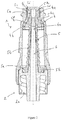
- FIG 1 representing a connector (1) for medical use according to the invention, it comprises a connector (2) integral with a chamber (3) and a ring assembly (4) (not visible in this figure) / elastic seal (5).
- the connector (2) is in the form of a composite part associating the body of the coupling (2) itself and a needle (6) (not visible in this figure).
- the chamber (3) comprises a first compartment (3a), a central compartment (3b) and a terminal compartment (3c).
- the terminal compartment (3c) of the chamber (3) has a section adapted to receive, by friction, a connector (7) male luer type.
- the first compartment (3a) of the chamber (3) cooperates with the connector (2), intended to receive a pipe in which a fluid circulates.
- the body of the connector (2) comprises a recess (2a) provided on its inner face with a screw thread intended to cooperate with a step of corresponding screw of a tubing or other female luer connector in which a fluid can flow.
- the body of the connector (2) is provided at its center with a needle (6) extending from the first compartment (3a) towards the end end of the central compartment (3b).
- the needle (6) itself is provided, near its free end, itself closed, two lateral orifices (6a) through which the fluid flows.
- the needle (6) is included in the impression of an elastic seal (5) provided with a ring (4) encircling its end portion at least as far as the area facing the orifices (6a) of the needle ( 6).
- This needle (6) has a substantially conical shape so as to promote its release under the effect of the thrust exerted by the connector (7) male luer type on the ring assembly (4) / elastic seal (5).
- the elastic seal (5) is made of silicone and is in the form of a tube of conical outer section, intended to extend into the chamber (3) from the body of the coupling (2) to the free end of the terminal compartment (3c) of the chamber (3).
- the seal (5) comprises a base portion (5a), a middle portion (5b) and an end portion (5c).
- the base portion (5a) of the elastic seal (5) is intended to rest on the body of the fitting (2). In the uncompressed position, that is to say in the relaxed position, neither the base portion (5a) of the elastic seal (5) nor the middle portion (5b) are in contact with the chamber (3).
- the base portion (5a) is provided with a continuous groove (5k) for preventing back leakage of liquid as previously explained.
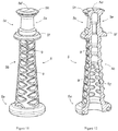
- the middle portion (5b) of the elastic seal (5) has a substantially conical shape and comprises in a first embodiment, illustrated in FIGS. Figures 9 and 10 , a succession of beads (8) defining, on the circumference of said seal (5), a corrugated shape symmetrical with respect to an axial plane of said elastic seal (5).
- This wavy shape corresponds to two periods of sinusoid.
- the shapes of the beads (8) can be likened to collapsed toric shapes on two opposite sides.
- the wall of said middle portion (5b) of the elastic seal (5) comprises on the circumference of said seal (5), a succession of non-through cavities (9) of elliptical shapes offset by a half not every 90 ° around said circumference.
- the circumference thus has a kind of alveolar wall, the cells of which are in the form of almonds.
- the expression "shifted by half a step” means in the case in point, shifted by half a cavity (9).
- the end portion (5c) of the elastic seal (5) is provided with a slot (5d), allowing the passage of the needle (6), when the elastic seal (5) is in a so-called "compressed” position, in other words, when the connector (1) is connected to a male type connector (7) luer.
- the end portion (5c) of the elastic seal (5) further comprises a recess (5e) downstream of the end of the needle (6) in the uncompressed position of the elastic seal (5).
- the end portion (5c) also has a flange (5f), which allows guiding and centering of said end portion (5c) of the elastic seal (5) in the central compartment (3b) of the chamber (3). To take into account the form and dimensions of the central compartment (3b) of the chamber (3), this collar (5f) is also circled by the ring (4).
- the elastic seal (5) has at its center, an imprint (5g) of a shape corresponding to that of the needle (6), the impression (5g) being however slightly longer than the needle (6).
- the inner section of the elastic seal (5) is smaller than the section of the needle (6) including in the end zone of the needle (6) covered by the ring (4) and including the lateral orifices (6a), at which the inner section of the elastic seal (5) is smaller than the section of the needle (6).
- the ring (4) is positioned at the end of the elastic seal (5) and has two sections of different sections, respectively a first cylindrical section (4a) circling the end portion (5c) of the elastic seal (5) to a corresponding length to the length of the terminal compartment (3c) and of section substantially equal to the section of said terminal compartment (3c) and a second cylindrical section (4b), of upper section substantially equal to the corresponding section of the central compartment (3b) and covering the flange (5f) of the elastic seal (5).
- the ring (4) is made of a rigid or semi-rigid material, possibly bi-material with the elastic seal (5), or separately, ring (4) and seal (5) being secured to one of the other especially by gluing or simple apposition.
- the outer section of the seal (5) is substantially equal to the inner section of the ring (4) on their overlap area.
- the end end of the elastic seal (5) has a deformable peripheral flange (5h) projecting over the end of said ring (4).
- This peripheral rim (5h) has an upper peripheral chamfer (5i) and a lower peripheral chamfer (5j).
- the two chamfers (5i, 5j) are made in such a way that they join to give a V-shape to said peripheral rim (5h), the point of which is directed towards the inner wall of the chamber (3).
- V shape of the deformable peripheral flange (5h) makes it possible to optimally adjust the outcropping of said flange (5h) relative to the internal stop (3d) of the free end of the chamber (3) and to obtain continuity of said free end of the chamber (3) with the elastic seal (5).
- the risks of contamination by bacteria are very clearly eliminated
- the tip of the V of the deformable peripheral flange (5h) is in contact with the inner edge (3d) of the free end of the chamber (3) and is flush with it.
- the deformable peripheral flange (5h) is intended to deform when the seal passes in a compressed position, or returns to a relaxed position.
- the deformation of the deformable peripheral flange (5h) against the inner wall luer of the free end of the chamber (3) is facilitated.
- said peripheral rim (5h) sandwiched between the cone (7a) of the connector (7) and the ring (4) bends upwards when the elastic seal (5) passes into a compressed position, and undergoes a symmetrical deformation, i.e.
- the end portion and more particularly the first cylindrical section (4a) of the ring (4) has two openings (4c) intended to promote the discharge of the plastic material at the time of the passage of the needle (6) under the effect the thrust created by the introduction of the connector (7) male luer type.
- the central compartment (3b) and the terminal compartment (3c) are connected by a shoulder serving as an abutment to the ring (4) circling the end end (5c) of the elastic seal (5) in the rest position; in the release position of the seal, thus ensuring that the deformable peripheral flange (5h) of the elastic seal (5) is flush with the internal stop (3d) of the free end of the chamber (3). ).
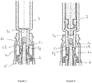
- the connected position is more precisely represented on the figure 6 by the installation of a connector (7) male luer type.
- This connector (7) is further provided with a luer cone (7a), intended to be inserted in the light of the terminal compartment (3c) of the chamber (3).
- the cone (7a) is supported by its end on the free end of the seal elastic (5). This support causes the elastic seal (5) to move along the barrel of the needle (6) towards the fitting (2), and then the needle tip (6) to pass through the slot (5d). ), facilitated by the recesses (5e), and finally the release of the lateral orifices (6a) and allowing the passage of the fluid.
- peripheral flange (5h) makes it possible, during the support of the cone (7a) of the connector (7) to luer male on the elastic seal (5), to crush the peripheral rim (5h) between said cone (7a) and the ring (4). This results in a better transfer of effort and a better centering of the ring (4) / seal (5) assembly relative to the chamber (3).
- the connection is made optimally. In addition, the tightness of the system is guaranteed
- the free part of the needle (6) is therefore in its entirety, contained in the inner channel of the cone (7a), thus allowing the transmission of the connector fluid (1) to connector (7).
- the movement of the ring (4) during this operation is a homogeneous and uniform axial movement due to the permanent contact of the walls of the section of the ring (4) with the central compartment (3b) of the chamber (3) while along the movement, with minimal friction.
- the part of the ring (4) of small section is in contact neither with the terminal compartment (3c) of the chamber (3), nor with the central compartment (3b) of the bedroom (3).
- the volume of the central compartment (3b) of the chamber (3) is provided to be able to contain the volume of the seal (5) in the compressed position.
- the invention provides a connector (1) for medical use giving full satisfaction of use.
- the total sealing of the system obtained upstream of the end slot (5d) of the elastic seal (5) is noted.
- the connector (1) according to the invention also allows a maximum sealing of the connection with another male connector (7) luer, a further decrease in the risk of bacterial contamination of the terminal end of the chamber (3), and a optimal centering of the elastic seal (5) relative to the end end of the chamber (3).
Priority Applications (1)
| Application Number | Priority Date | Filing Date | Title |
|---|---|---|---|
| PL13758956T PL2882487T3 (pl) | 2012-08-10 | 2013-08-08 | Złączka do zastosowań medycznych |
Applications Claiming Priority (2)
| Application Number | Priority Date | Filing Date | Title |
|---|---|---|---|
| FR1257767A FR2994392B1 (fr) | 2012-08-10 | 2012-08-10 | Connecteur a usage medical |
| PCT/FR2013/051912 WO2014023921A1 (fr) | 2012-08-10 | 2013-08-08 | Connecteur a usage médical |
Publications (2)
| Publication Number | Publication Date |
|---|---|
| EP2882487A1 EP2882487A1 (fr) | 2015-06-17 |
| EP2882487B1 true EP2882487B1 (fr) | 2019-06-05 |
Family
ID=47088930
Family Applications (1)
| Application Number | Title | Priority Date | Filing Date |
|---|---|---|---|
| EP13758956.0A Active EP2882487B1 (fr) | 2012-08-10 | 2013-08-08 | Connecteur a usage médical |
Country Status (9)
| Country | Link |
|---|---|
| US (1) | US10016586B2 (zh) |
| EP (1) | EP2882487B1 (zh) |
| CN (1) | CN104394925B (zh) |
| BR (1) | BR112014031085B1 (zh) |
| ES (1) | ES2732084T3 (zh) |
| FR (1) | FR2994392B1 (zh) |
| PL (1) | PL2882487T3 (zh) |
| TR (1) | TR201910023T4 (zh) |
| WO (1) | WO2014023921A1 (zh) |
Families Citing this family (16)
| Publication number | Priority date | Publication date | Assignee | Title |
|---|---|---|---|---|
| EP2968894B1 (en) | 2013-03-15 | 2017-07-19 | ICU Medical, Inc. | Medical connector |
| EP2862587A1 (en) | 2013-10-15 | 2015-04-22 | Becton Dickinson France | Tip cap assembly for closing an injection system |
| CA2932124C (en) | 2013-12-11 | 2023-05-09 | Icu Medical, Inc. | Check valve |
| USD786427S1 (en) | 2014-12-03 | 2017-05-09 | Icu Medical, Inc. | Fluid manifold |
| USD793551S1 (en) | 2014-12-03 | 2017-08-01 | Icu Medical, Inc. | Fluid manifold |
| TWI584837B (zh) * | 2015-02-09 | 2017-06-01 | 怡安醫療器材股份有限公司 | 免針連接頭模組 |
| ITUB20151860A1 (it) * | 2015-07-02 | 2017-01-02 | Gvs Spa | Connettore medicale perfezionato |
| EP3011994B1 (fr) | 2015-08-10 | 2018-10-10 | Cair L. G. L. | Connecteur luer femelle |
| WO2017049015A1 (en) * | 2015-09-15 | 2017-03-23 | Dr. Py Institute Llc | Septum that decontaminates by interaction with penetrating element |
| DE102016203518A1 (de) * | 2016-03-03 | 2017-09-07 | B. Braun Melsungen Ag | Verbindungseinrichtung eines medizinischen Infusionssystems |
| US11524149B2 (en) * | 2016-03-10 | 2022-12-13 | Np Medical Inc. | Unitary medical connector with a rigid and a resilient portion |
| CN109562372A (zh) * | 2016-06-15 | 2019-04-02 | 汉密尔顿公司 | 移液装置、移液管末梢联接器和移液管末梢:装置和方法 |
| EP3517164B1 (en) | 2016-09-26 | 2021-09-08 | Terumo Kabushiki Kaisha | Male connector, medical instrument, and connection method |
| WO2018106508A1 (en) * | 2016-12-09 | 2018-06-14 | 3M Innovative Properties Company | Disinfecting cap for open female luer devices |
| US11213456B2 (en) * | 2019-10-25 | 2022-01-04 | Zachary Zuppardo | Apparatus for providing instant access to a medical vial and a method for using the same |
| GB2589134A (en) * | 2019-11-22 | 2021-05-26 | Overx Medical Ltd | A connector |
Family Cites Families (7)
| Publication number | Priority date | Publication date | Assignee | Title |
|---|---|---|---|---|
| US5549566A (en) * | 1994-10-27 | 1996-08-27 | Abbott Laboratories | Valved intravenous fluid line infusion device |
| US5738663A (en) * | 1995-12-15 | 1998-04-14 | Icu Medical, Inc. | Medical valve with fluid escape space |
| US6113068A (en) * | 1998-10-05 | 2000-09-05 | Rymed Technologies | Swabbable needleless injection port system having low reflux |
| US6994315B2 (en) * | 2004-01-13 | 2006-02-07 | Rymed Technologies, Inc. | Swabbable needle-free injection port valve system with neutral fluid displacement |
| FR2894150B1 (fr) * | 2005-12-05 | 2008-01-04 | Ace Dev Solution Soc A Respons | Connecteur a usage medical |
| IT1396791B1 (it) * | 2009-11-26 | 2012-12-14 | Borla Ind | Connettore luer maschio valvolare |
| US8758306B2 (en) * | 2010-05-17 | 2014-06-24 | Icu Medical, Inc. | Medical connectors and methods of use |
-
2012
- 2012-08-10 FR FR1257767A patent/FR2994392B1/fr not_active Expired - Fee Related
-
2013
- 2013-08-08 CN CN201380031850.1A patent/CN104394925B/zh active Active
- 2013-08-08 TR TR2019/10023T patent/TR201910023T4/tr unknown
- 2013-08-08 EP EP13758956.0A patent/EP2882487B1/fr active Active
- 2013-08-08 BR BR112014031085-8A patent/BR112014031085B1/pt active IP Right Grant
- 2013-08-08 WO PCT/FR2013/051912 patent/WO2014023921A1/fr active Application Filing
- 2013-08-08 PL PL13758956T patent/PL2882487T3/pl unknown
- 2013-08-08 US US14/407,374 patent/US10016586B2/en active Active
- 2013-08-08 ES ES13758956T patent/ES2732084T3/es active Active
Non-Patent Citations (1)
| Title |
|---|
| None * |
Also Published As
| Publication number | Publication date |
|---|---|
| BR112014031085A2 (pt) | 2017-06-27 |
| US20150126942A1 (en) | 2015-05-07 |
| PL2882487T3 (pl) | 2019-09-30 |
| FR2994392B1 (fr) | 2014-08-08 |
| BR112014031085B1 (pt) | 2021-03-16 |
| US10016586B2 (en) | 2018-07-10 |
| CN104394925A (zh) | 2015-03-04 |
| ES2732084T3 (es) | 2019-11-20 |
| CN104394925B (zh) | 2018-01-16 |
| FR2994392A1 (fr) | 2014-02-14 |
| EP2882487A1 (fr) | 2015-06-17 |
| WO2014023921A1 (fr) | 2014-02-13 |
| TR201910023T4 (tr) | 2019-08-21 |
Similar Documents
| Publication | Publication Date | Title |
|---|---|---|
| EP2882487B1 (fr) | Connecteur a usage médical | |
| EP1890760B1 (fr) | Connecteur à usage médical | |
| EP2878873B1 (fr) | Dispositif de raccordement rapide de type cartouche | |
| EP1273843B1 (fr) | Raccord récupérable adaptable aux extrémités d'un tuyau souple armé | |
| WO2013135905A1 (fr) | Ensemble sécurisé de transfert de liquide à usage médical | |
| CA2790033A1 (fr) | Ensemble de connecteurs facilement nettoyable pour un circuit liquide | |
| FR2753774A1 (fr) | Connecteur rapide a verrouillage | |
| EP2950876B1 (fr) | Connecteur à usage médical perfectionné | |
| CA2696837A1 (en) | Seal having a large compression range | |
| WO2015150646A1 (fr) | Ensemble de seringue anti-reflux | |
| FR2987097A1 (fr) | Dispositif de raccordement etanche sans zone de retention | |
| FR2737275A1 (fr) | Raccord de tuyaux antiseparation | |
| EP2162663A2 (fr) | Raccord a lavage exterieur facilite | |
| EP0526373B1 (fr) | Assemblage verrouillé de tuyaux avec garniture d'étanchéité composite | |
| FR2863032A1 (fr) | Raccord a sertir pour tubes multicouches | |
| WO2009118417A1 (fr) | Connecteur a usage medical ameliore | |
| EP4061767A1 (fr) | Embout de récipient de liquide | |
| FR2952813A1 (fr) | Dispositif de liaison entre deux contenants, destine notamment a un usage medical | |
| BE1018353A5 (fr) | Dispositif de raccordement de tuyauteries pour siphon. | |
| WO2020161401A1 (fr) | Bouchon hermétique pour embout | |
| FR3018067A1 (fr) | Dispositif d'obturation orientable | |
| FR2736836A1 (fr) | Dispositif de connexion pour catheter | |
| FR3008159A1 (fr) | Dispositif de raccordement a zones externes reduites de retention de poussiere | |
| FR3021882A1 (fr) | Canule anti-reflux | |
| FR2684163A1 (fr) | Dispositif de bagues d'etancheite formant joint pour raccordement souple entre deux elements. |
Legal Events
| Date | Code | Title | Description |
|---|---|---|---|
| PUAI | Public reference made under article 153(3) epc to a published international application that has entered the european phase |
Free format text: ORIGINAL CODE: 0009012 |
|
| 17P | Request for examination filed |
Effective date: 20141218 |
|
| AK | Designated contracting states |
Kind code of ref document: A1 Designated state(s): AL AT BE BG CH CY CZ DE DK EE ES FI FR GB GR HR HU IE IS IT LI LT LU LV MC MK MT NL NO PL PT RO RS SE SI SK SM TR |
|
| AX | Request for extension of the european patent |
Extension state: BA ME |
|
| DAX | Request for extension of the european patent (deleted) | ||
| STAA | Information on the status of an ep patent application or granted ep patent |
Free format text: STATUS: EXAMINATION IS IN PROGRESS |
|
| 17Q | First examination report despatched |
Effective date: 20180614 |
|
| GRAP | Despatch of communication of intention to grant a patent |
Free format text: ORIGINAL CODE: EPIDOSNIGR1 |
|
| STAA | Information on the status of an ep patent application or granted ep patent |
Free format text: STATUS: GRANT OF PATENT IS INTENDED |
|
| INTG | Intention to grant announced |
Effective date: 20181220 |
|
| GRAS | Grant fee paid |
Free format text: ORIGINAL CODE: EPIDOSNIGR3 |
|
| GRAA | (expected) grant |
Free format text: ORIGINAL CODE: 0009210 |
|
| STAA | Information on the status of an ep patent application or granted ep patent |
Free format text: STATUS: THE PATENT HAS BEEN GRANTED |
|
| AK | Designated contracting states |
Kind code of ref document: B1 Designated state(s): AL AT BE BG CH CY CZ DE DK EE ES FI FR GB GR HR HU IE IS IT LI LT LU LV MC MK MT NL NO PL PT RO RS SE SI SK SM TR |
|
| REG | Reference to a national code |
Ref country code: GB Ref legal event code: FG4D Free format text: NOT ENGLISH |
|
| REG | Reference to a national code |
Ref country code: CH Ref legal event code: EP |
|
| REG | Reference to a national code |
Ref country code: AT Ref legal event code: REF Ref document number: 1139382 Country of ref document: AT Kind code of ref document: T Effective date: 20190615 |
|
| REG | Reference to a national code |
Ref country code: DE Ref legal event code: R096 Ref document number: 602013056209 Country of ref document: DE |
|
| REG | Reference to a national code |
Ref country code: IE Ref legal event code: FG4D Free format text: LANGUAGE OF EP DOCUMENT: FRENCH Ref country code: NL Ref legal event code: FP |
|
| REG | Reference to a national code |
Ref country code: LT Ref legal event code: MG4D |
|
| PG25 | Lapsed in a contracting state [announced via postgrant information from national office to epo] |
Ref country code: NO Free format text: LAPSE BECAUSE OF FAILURE TO SUBMIT A TRANSLATION OF THE DESCRIPTION OR TO PAY THE FEE WITHIN THE PRESCRIBED TIME-LIMIT Effective date: 20190905 Ref country code: AL Free format text: LAPSE BECAUSE OF FAILURE TO SUBMIT A TRANSLATION OF THE DESCRIPTION OR TO PAY THE FEE WITHIN THE PRESCRIBED TIME-LIMIT Effective date: 20190605 Ref country code: FI Free format text: LAPSE BECAUSE OF FAILURE TO SUBMIT A TRANSLATION OF THE DESCRIPTION OR TO PAY THE FEE WITHIN THE PRESCRIBED TIME-LIMIT Effective date: 20190605 Ref country code: HR Free format text: LAPSE BECAUSE OF FAILURE TO SUBMIT A TRANSLATION OF THE DESCRIPTION OR TO PAY THE FEE WITHIN THE PRESCRIBED TIME-LIMIT Effective date: 20190605 Ref country code: SE Free format text: LAPSE BECAUSE OF FAILURE TO SUBMIT A TRANSLATION OF THE DESCRIPTION OR TO PAY THE FEE WITHIN THE PRESCRIBED TIME-LIMIT Effective date: 20190605 Ref country code: LT Free format text: LAPSE BECAUSE OF FAILURE TO SUBMIT A TRANSLATION OF THE DESCRIPTION OR TO PAY THE FEE WITHIN THE PRESCRIBED TIME-LIMIT Effective date: 20190605 |
|
| REG | Reference to a national code |
Ref country code: ES Ref legal event code: FG2A Ref document number: 2732084 Country of ref document: ES Kind code of ref document: T3 Effective date: 20191120 |
|
| PG25 | Lapsed in a contracting state [announced via postgrant information from national office to epo] |
Ref country code: GR Free format text: LAPSE BECAUSE OF FAILURE TO SUBMIT A TRANSLATION OF THE DESCRIPTION OR TO PAY THE FEE WITHIN THE PRESCRIBED TIME-LIMIT Effective date: 20190906 Ref country code: BG Free format text: LAPSE BECAUSE OF FAILURE TO SUBMIT A TRANSLATION OF THE DESCRIPTION OR TO PAY THE FEE WITHIN THE PRESCRIBED TIME-LIMIT Effective date: 20190905 Ref country code: RS Free format text: LAPSE BECAUSE OF FAILURE TO SUBMIT A TRANSLATION OF THE DESCRIPTION OR TO PAY THE FEE WITHIN THE PRESCRIBED TIME-LIMIT Effective date: 20190605 Ref country code: LV Free format text: LAPSE BECAUSE OF FAILURE TO SUBMIT A TRANSLATION OF THE DESCRIPTION OR TO PAY THE FEE WITHIN THE PRESCRIBED TIME-LIMIT Effective date: 20190605 |
|
| REG | Reference to a national code |
Ref country code: AT Ref legal event code: MK05 Ref document number: 1139382 Country of ref document: AT Kind code of ref document: T Effective date: 20190605 |
|
| PG25 | Lapsed in a contracting state [announced via postgrant information from national office to epo] |
Ref country code: CZ Free format text: LAPSE BECAUSE OF FAILURE TO SUBMIT A TRANSLATION OF THE DESCRIPTION OR TO PAY THE FEE WITHIN THE PRESCRIBED TIME-LIMIT Effective date: 20190605 Ref country code: RO Free format text: LAPSE BECAUSE OF FAILURE TO SUBMIT A TRANSLATION OF THE DESCRIPTION OR TO PAY THE FEE WITHIN THE PRESCRIBED TIME-LIMIT Effective date: 20190605 Ref country code: AT Free format text: LAPSE BECAUSE OF FAILURE TO SUBMIT A TRANSLATION OF THE DESCRIPTION OR TO PAY THE FEE WITHIN THE PRESCRIBED TIME-LIMIT Effective date: 20190605 Ref country code: EE Free format text: LAPSE BECAUSE OF FAILURE TO SUBMIT A TRANSLATION OF THE DESCRIPTION OR TO PAY THE FEE WITHIN THE PRESCRIBED TIME-LIMIT Effective date: 20190605 Ref country code: SK Free format text: LAPSE BECAUSE OF FAILURE TO SUBMIT A TRANSLATION OF THE DESCRIPTION OR TO PAY THE FEE WITHIN THE PRESCRIBED TIME-LIMIT Effective date: 20190605 Ref country code: PT Free format text: LAPSE BECAUSE OF FAILURE TO SUBMIT A TRANSLATION OF THE DESCRIPTION OR TO PAY THE FEE WITHIN THE PRESCRIBED TIME-LIMIT Effective date: 20191007 |
|
| PG25 | Lapsed in a contracting state [announced via postgrant information from national office to epo] |
Ref country code: SM Free format text: LAPSE BECAUSE OF FAILURE TO SUBMIT A TRANSLATION OF THE DESCRIPTION OR TO PAY THE FEE WITHIN THE PRESCRIBED TIME-LIMIT Effective date: 20190605 Ref country code: IS Free format text: LAPSE BECAUSE OF FAILURE TO SUBMIT A TRANSLATION OF THE DESCRIPTION OR TO PAY THE FEE WITHIN THE PRESCRIBED TIME-LIMIT Effective date: 20191005 |
|
| REG | Reference to a national code |
Ref country code: DE Ref legal event code: R097 Ref document number: 602013056209 Country of ref document: DE |
|
| PLBE | No opposition filed within time limit |
Free format text: ORIGINAL CODE: 0009261 |
|
| STAA | Information on the status of an ep patent application or granted ep patent |
Free format text: STATUS: NO OPPOSITION FILED WITHIN TIME LIMIT |
|
| PG25 | Lapsed in a contracting state [announced via postgrant information from national office to epo] |
Ref country code: DK Free format text: LAPSE BECAUSE OF FAILURE TO SUBMIT A TRANSLATION OF THE DESCRIPTION OR TO PAY THE FEE WITHIN THE PRESCRIBED TIME-LIMIT Effective date: 20190605 |
|
| 26N | No opposition filed |
Effective date: 20200306 |
|
| PG25 | Lapsed in a contracting state [announced via postgrant information from national office to epo] |
Ref country code: SI Free format text: LAPSE BECAUSE OF FAILURE TO SUBMIT A TRANSLATION OF THE DESCRIPTION OR TO PAY THE FEE WITHIN THE PRESCRIBED TIME-LIMIT Effective date: 20190605 Ref country code: MC Free format text: LAPSE BECAUSE OF FAILURE TO SUBMIT A TRANSLATION OF THE DESCRIPTION OR TO PAY THE FEE WITHIN THE PRESCRIBED TIME-LIMIT Effective date: 20190605 Ref country code: LU Free format text: LAPSE BECAUSE OF NON-PAYMENT OF DUE FEES Effective date: 20190808 |
|
| PG25 | Lapsed in a contracting state [announced via postgrant information from national office to epo] |
Ref country code: IE Free format text: LAPSE BECAUSE OF NON-PAYMENT OF DUE FEES Effective date: 20190808 |
|
| PG25 | Lapsed in a contracting state [announced via postgrant information from national office to epo] |
Ref country code: CY Free format text: LAPSE BECAUSE OF FAILURE TO SUBMIT A TRANSLATION OF THE DESCRIPTION OR TO PAY THE FEE WITHIN THE PRESCRIBED TIME-LIMIT Effective date: 20190605 |
|
| PG25 | Lapsed in a contracting state [announced via postgrant information from national office to epo] |
Ref country code: MT Free format text: LAPSE BECAUSE OF FAILURE TO SUBMIT A TRANSLATION OF THE DESCRIPTION OR TO PAY THE FEE WITHIN THE PRESCRIBED TIME-LIMIT Effective date: 20190605 Ref country code: HU Free format text: LAPSE BECAUSE OF FAILURE TO SUBMIT A TRANSLATION OF THE DESCRIPTION OR TO PAY THE FEE WITHIN THE PRESCRIBED TIME-LIMIT; INVALID AB INITIO Effective date: 20130808 |
|
| PG25 | Lapsed in a contracting state [announced via postgrant information from national office to epo] |
Ref country code: MK Free format text: LAPSE BECAUSE OF FAILURE TO SUBMIT A TRANSLATION OF THE DESCRIPTION OR TO PAY THE FEE WITHIN THE PRESCRIBED TIME-LIMIT Effective date: 20190605 |
|
| PGFP | Annual fee paid to national office [announced via postgrant information from national office to epo] |
Ref country code: NL Payment date: 20230726 Year of fee payment: 11 |
|
| PGFP | Annual fee paid to national office [announced via postgrant information from national office to epo] |
Ref country code: TR Payment date: 20230727 Year of fee payment: 11 Ref country code: IT Payment date: 20230809 Year of fee payment: 11 Ref country code: ES Payment date: 20230907 Year of fee payment: 11 Ref country code: CH Payment date: 20230902 Year of fee payment: 11 Ref country code: GB Payment date: 20230824 Year of fee payment: 11 |
|
| PGFP | Annual fee paid to national office [announced via postgrant information from national office to epo] |
Ref country code: PL Payment date: 20230721 Year of fee payment: 11 Ref country code: FR Payment date: 20230828 Year of fee payment: 11 Ref country code: DE Payment date: 20230808 Year of fee payment: 11 Ref country code: BE Payment date: 20230822 Year of fee payment: 11 |