EP2882052A2 - Wärmeregulierung des Kastens einer elektrischen Schaltanlage in einem Hafen - Google Patents
Wärmeregulierung des Kastens einer elektrischen Schaltanlage in einem Hafen Download PDFInfo
- Publication number
- EP2882052A2 EP2882052A2 EP14187786.0A EP14187786A EP2882052A2 EP 2882052 A2 EP2882052 A2 EP 2882052A2 EP 14187786 A EP14187786 A EP 14187786A EP 2882052 A2 EP2882052 A2 EP 2882052A2
- Authority
- EP
- European Patent Office
- Prior art keywords
- temperature
- compartment
- enclosure
- air
- extraction
- Prior art date
- Legal status (The legal status is an assumption and is not a legal conclusion. Google has not performed a legal analysis and makes no representation as to the accuracy of the status listed.)
- Granted
Links
Images



Classifications
-
- H—ELECTRICITY
- H02—GENERATION; CONVERSION OR DISTRIBUTION OF ELECTRIC POWER
- H02B—BOARDS, SUBSTATIONS OR SWITCHING ARRANGEMENTS FOR THE SUPPLY OR DISTRIBUTION OF ELECTRIC POWER
- H02B1/00—Frameworks, boards, panels, desks, casings; Details of substations or switching arrangements
- H02B1/56—Cooling; Ventilation
- H02B1/565—Cooling; Ventilation for cabinets
-
- H—ELECTRICITY
- H05—ELECTRIC TECHNIQUES NOT OTHERWISE PROVIDED FOR
- H05K—PRINTED CIRCUITS; CASINGS OR CONSTRUCTIONAL DETAILS OF ELECTRIC APPARATUS; MANUFACTURE OF ASSEMBLAGES OF ELECTRICAL COMPONENTS
- H05K7/00—Constructional details common to different types of electric apparatus
- H05K7/20—Modifications to facilitate cooling, ventilating, or heating
- H05K7/2089—Modifications to facilitate cooling, ventilating, or heating for power electronics, e.g. for inverters for controlling motor
- H05K7/20945—Thermal management, e.g. inverter temperature control
-
- H—ELECTRICITY
- H01—ELECTRIC ELEMENTS
- H01F—MAGNETS; INDUCTANCES; TRANSFORMERS; SELECTION OF MATERIALS FOR THEIR MAGNETIC PROPERTIES
- H01F27/00—Details of transformers or inductances, in general
- H01F27/08—Cooling; Ventilating
- H01F27/085—Cooling by ambient air
-
- H—ELECTRICITY
- H02—GENERATION; CONVERSION OR DISTRIBUTION OF ELECTRIC POWER
- H02B—BOARDS, SUBSTATIONS OR SWITCHING ARRANGEMENTS FOR THE SUPPLY OR DISTRIBUTION OF ELECTRIC POWER
- H02B7/00—Enclosed substations, e.g. compact substations
- H02B7/06—Distribution substations, e.g. for urban network
Definitions
- the invention relates to the thermal regulation of shore power supply stations by the terrestrial electrical distribution network, said stations being able to provide a frequency conversion, in particular from 50 to 60 Hz, and being housed in a metal enclosure.
- the invention relates to a frequency conversion compartment or a voltage transforming compartment of such a station and to the elements enabling said regulation.
- the electrical networks used on the ships are generally of the medium-voltage type, which makes it possible to use smaller section cables and reduce energy losses in the power supply of ship networks.
- a ship When a ship is docked, in order to stop its generator set, it must have a facility in the port for the power of its equipment with an adequate power source.
- the required power can be large, from 1 MVA up to 20 MVA depending on whether it is a bulk carrier, a ferry, a container ship, a liner, ... under tension different, in particular 6.6 kV or 11 kV according to IEC 80005-1 standards;
- the vessels have, according to their type, electrical equipment operating in 50 or 60 Hz.
- the ships requiring, with variable constraints according to their type, a good continuity of the power supply while they are docked, port feeding must be continuous even after default.
- shore power facilities are subject to constraints inherent to their location, by definition near water, often salty. What's more, ports want as compact a facility as possible.
- the metal station 10 makes it possible to convert a first input power voltage supplied by a network 12 into a second output power voltage intended to power a ship's electrical network 14, which may be of frequency and / or or different voltage.
- the IEC 62271-202 standard recommends natural ventilation for voltage transformers 105: an air intake in the low position and an air outlet in the high position associated with the heating of the air by the air. apparatus in operation thus provide convection natural and an air renewal of several cubic meters per hour.
- the ventilation can be forced in addition by an air circulation device that can be operated or not according to a chosen parameter such as temperature, to remove hot-spot peaks.
- the GFC 205 do not have internal temperature regulation or condensation protection: except for air-conditioned cases, they are placed in housing with natural ventilation, possibly forced, sometimes associated with heating the compartment to reduce the relative humidity of the air.
- the frequency converters 205 generally include heat pipes that freeze in case of negative temperature: a temperature control before starting to place the equipment in good conditions is therefore desirable.
- the dedicated compartment 200 can thus implement an independent temperature control that activates or not the dedicated ventilation.
- the station 10 being installed in a port environment, it is essential to protect the electrical equipment from the external environment, including salt air: suitable filters are placed on the air intakes. But this type of filter is very expensive to replace; to reduce their clogging and thus the maintenance costs, it is desirable to optimize the air flow of a forced ventilation in particular.
- the invention aims at overcoming the drawbacks of existing shore power stations by proposing a system for regulating the ventilation of the compartments of this type of station, said system taking into account the different settings. Due to the regulation and the optimization of the ventilation which results from it, the operation of the electrical devices of the compartments of the supply station is also optimized, which makes it possible to realize a more compact station, the devices being dimensioned at the most just requested abilities. In addition, this regulation allows less aging of the various components by optimizing their operating conditions.
- the invention thus relates to a port power station compartment comprising a housing housing a transformer, preferably of dry type with three medium voltage windings and three low voltage windings.
- the chamber is provided with air inlet means provided with filters adapted preferably to saline air, advantageously in the form of two boxes on two opposite walls of the enclosure, and located towards the bottom of the station; the chamber is also provided with air outlet means, preferably on the roof of the enclosure or on any high end portion.
- the enclosure also houses means for measuring the internal temperature of the enclosure, for example at the air outlet, and means for measuring the temperature of the transformer, preferably three sensors at its windings.
- the enclosure is provided with air extraction means, housed at the outlet of air, and tangential ventilation means, preferably housed to the air inlets, below the windings of the transformer.
- the compartment further comprises regulating means adapted to control the start and the speed of the air extraction means and the ventilation means according to the temperature data.
- the regulating means comprise means for starting the tangential ventilation means when one of the transformer temperature sensors exceeds a first threshold and for stopping them when the measurement of all the transformer temperature sensors is less than a second one. threshold.
- the regulation means comprise a backup mode in which the tangential ventilation means are not stopped after they start.
- the regulating means also comprise means for imposing an air flow rate as a function of the temperature of the enclosure on the extraction means when said temperature exceeds a first value; the first value can be determined according to the outside temperature given by appropriate means.
- the invention also relates to a port power station comprising at least one, in particular two, previous compartments, and preferably a frequency conversion compartment.
- the station comprises a metal enclosure with internal walls delimiting said compartments, and wherein two compartments with transformer surround the frequency conversion compartment.
- the frequency conversion compartment may comprise forced ventilation means, and the regulating means of the transformer compartments may then comprise means for starting the extraction means of said compartment when a detection signal of the forced ventilation of the compartment of the transformer compartment. Frequency conversion reaches him.
- the invention in a second aspect, relates to a port power station compartment comprising a housing housing frequency conversion means, preferably in the form of a plurality of network or GFC frequency converters.
- the enclosure is provided with air inlet means provided with filters adapted preferably to saline air, advantageously in the form of caissons on two opposite walls of the enclosure, and located towards the bottom of the station; the chamber is also provided with air outlet means, preferably on the roof of the enclosure or on any high end portion.
- the enclosure also houses means for measuring the internal temperature of the enclosure, a heating device, and preferably means for measuring the degree of humidity within the enclosure.
- the chamber is provided with air extraction means, housed at the outlet of air, and means for ventilating the conversion means, preferably associated with each of the GFCs, in particular integral part.
- the compartment further comprises regulating means adapted to control the speed of the air extraction means and the ventilation means according to the temperature data, and secondarily to the degree of humidity.
- the compartment further comprises means for verifying the environmental conditions inside the enclosure and for starting the conversion means when these conditions are met.
- the environmental conditions is the verification that the temperature exceeds a lower limit, and that the degree of humidity is sufficiently low.
- the verification means are preferably associated with the regulation means.
- the regulating means comprise means for starting the heating device when the temperature is lower than a first value, as well as when the degree of humidity is greater than a threshold and the temperature below a second value.
- the regulating means also comprise means for starting the ventilation means when the humidity level is above said threshold, and the temperature above the second value.
- the regulating means also comprise means for starting the extraction means when the temperature is greater than a limit value, and for imposing, when the conversion means are in operation, a speed at said means depending on the internal temperature, thus possibly external temperature and / or dissipated power.
- the invention also relates to a port power station comprising at least one such compartment and compartments housing voltage transformers, preferably surrounding it, the various compartments being advantageously housed in the same metal enclosure and separated by internal walls of the enclosure.
- the control method when the time between ventilation and start-up exceeds a predetermined time, includes maintaining the environmental conditions by implementing heating, ventilation, or air extraction. depending on the temperature and the degree of humidity.
- a docking station 10 is composed of a metal enclosure 30 having four compartments separated by internal walls. As illustrated in figure 2 three of the compartments of the station 10 comprise natural ventilation means, the fourth 20 being sealed.
- the natural ventilation means comprise air inlet means 40, situated towards the bottom of the container 30, and air outlet means 50 upwards, preferably in the form of a chimney or turret.
- the air intake means are in the form of ventilation boxes 40 located at the bottom of two opposite walls of the container 30 common to all compartments 20, 100, 200, which preferably include (see FIG. Figures 3 and 5 ) filters 42 adapted to the saline air (pre-filter + final filter), and a gate 44 guaranteeing a degree of protection higher than the minimum value imposed by the IEC 62271-202 standard, in particular against the mechanical impacts of a value 20 joules, or in accordance with an IP23D according to IEC 60529.
- the number of boxes 40 is determined by the air flow necessary to ensure the cooling of the devices contained in each compartment 100, 200, 100 ', and the available space; in particular, as schematized for a station 10 of 3 MVA, a box 40 is located on the two opposite sides of a voltage transformer compartment 100, while the longer frequency conversion compartment 200, comprising 6 GFCs, is provided with twice four caissons 40.
- the air outlet means 50 are provided with a roof hood with grids 52 to ensure the protection indices against the penetration of solid and liquid IP and IK shock imposed by IEC 62271- 202; optionally, an overpressure leaflet makes it possible to improve the protection against the conditions of external services when the installation is stopped.
- the number of air outlets 50 depends on the efficiency of the required airflow: it is thus preferred to have several turrets on the "long" frequency conversion compartment 200, three double in the illustrated embodiment, rather than a wide chimney.
- a voltage transforming compartment 100 thus comprises, as illustrated in FIG. figure 3 , a metal casing 30 with two air inlets 40 provided with filters 42 and an air outlet turret 50 which houses a voltage transformer 105 of the dry type, a choice making it possible to better satisfy the regulatory provisions against fires in harbor environment . Due to the filtered ventilation which does not generate a deposit of salt, the transformer 105 can be of traditional "paper" type, without particular protection of the low-voltage winding, and it is not necessary to use a transformer to Reinforced "double cast” protection, resin, heavier, bigger and more expensive.
- the ventilation of the transformer 105 is carried out in a controlled manner. Since the voltage transformation compartments 100 surround a frequency conversion compartment 200 whose devices are sensitive, it is advisable not to transmit air, or as little as possible, minimizing the amount of air passing through the internal walls. of the enclosure 30 between compartments 100, 200: a flow by air depression is therefore chosen, with air extraction means 150 centrifugal fan type with integrated speed variation placed in the output in the turret 50 rather than a wind tunnel. Furthermore, according to the invention, the transformer 105 is "boosted", that is to say that it is used in extreme conditions; in particular, the theoretical capacity of the transformer 105 is increased.
- the airflow is directed in a laminar manner along the windings 110 by virtue of the presence of radial or tangential ventilation devices 140 located under the windings 110 of the transformer 105, in order to direct the flow ; the flow rate of said ventilation devices 140 is substantially lower than the flow rate of the extractor 150 in order to maintain a laminar flow.
- tangential fans 140 are placed on each side at the bottom of the transformer 105; coupled to the driving force of the flow generated by the extractor 150 and dimensioned to balance said force, the main flow of air is relayed in the windings 110 with air free of impurities such as salt or dust through filter 42 itself protected by the grids 44 of the air intake boxes 40.
- the transformer 105 is slightly raised relative to the bottom of the station 10 to ensure that the air pushed into the windings 110 is sucked on more directly possible from the filter boxes 40. The air is expelled through the outlet grilles 52 installed on the turret or roof box 50.
- a temperature control is coupled to the ventilation of the transformer 105, including controlled regulation.
- the transformation compartment 100 is further equipped with three temperature sensors 160 in the LV windings 110 and a temperature sensor 165 located near the air outlet 50.
- the internal ambient temperature of the compartment 100 is measured by the output sensor 165.
- T 100_ref a threshold for example set at 35 ° C
- the air extractor 150 is started.
- the threshold T 100_ref is adjusted according to the external temperature T ext : for example T 100_ref is equal to T ext + T 100_gap while remaining in all cases greater than a minimum reference temperature T 100_ref_min .
- the station 10 thus comprises a control automaton for the compartment 100, for example located in the first compartment 20.
- this controller is connected to the protection relay (for example of the SEPAM type) to which the MV windings of the transformer 105 are connected. and it can be adapted to start and adjust the rotational speed V 150 of the air extractor 150 by suitable means.
- a trigger protection systems 25 takes place and the station 10 is stopped.
- a preferred regulation system is schematized in figure 4 . It can be noted an additional step of triggering the forced ventilation for external cause. In fact, although desirable, it is rare to have a perfect seal between the compartments 100, 200 in a compact metal power station 10. In particular, if a forced ventilation is started in the adjacent compartment of conversion of frequency 200, the air of the voltage transforming compartment 100, 100 'will be sucked up: the regulation according to the invention therefore provides for a start of the air extractors 150 of the voltage compartments 100, 100' as soon as a forced ventilation is started in the adjacent compartment 200, and a constant low speed operation V 150_min .
- GFCs are used as frequency converters: this type of device, proven, can optimize performance in terms of energy efficiency and network pollution.
- the number of conversion units 205 is chosen according to the characteristics of the feed station 10; in particular, for a 3 MVA substation, 6 GFCs of the 500 kVA type are used in two rows, whereas for a 2 MVA station only four can be used.
- the GFC 205 does not include regulation so that ventilation operates at full power regardless of load, temperature and humidity. It is therefore necessary to set up an additional ventilation system of the compartment 200 which comprises control means taking these variables into account in order to guarantee the GFC 205 optimal operating conditions.
- the same extractor solution 250 located in the turret 50 is chosen; here again it is preferable to have laminar air flows.
- the extractors 250 are chosen so as not to be biased to their maximum capacity so that their speed is limited to the power input of 2300W, for example at about 1950 rpm.
- the GFC 205s imply other constraints: despite the presence of the filters 42 which prevent the introduction of sea air, the condensation proves to be very problematic and it is It is important to check that the airflow is sufficient to prevent the deposition of moisture on the GFC 205.
- the GFC 205 can be stored with negative temperatures, they can only operate with temperatures higher than 200 T 5 ° C because of the water present in the heat pipes; their only commissioning requires that the water can circulate, under pain of destruction.
- heating is therefore recommended in the frequency conversion compartment 200; different means are possible, in particular with the presence of a dedicated heating device 220, whose power can be optimized (at first approach, for a 3 MVA station, a device 220 of the 2 ⁇ 3 ⁇ 2 kW type is used, and a 2 ⁇ 2 ⁇ 2 kW device for 2 MVA).
- This type of monitoring can naturally be used in the transformer compartment 100 but is unnecessary, especially with dry transformers, insensitive to temperature and / or the presence of "natural" condensation (excluding salt air).
- the condensation in the compartment can be avoided by two principles: the heating or the internal ventilation of the GFC 205 which can be controlled by the control of the station 10.
- the heating allows an increase in temperature with a concomitant lowering of the degree of humidity; when the temperature T 200 is high, it is not reasonable to use heating, both because the temperature can become problematic for the devices 205 that for reasons of energy efficiency, and a running fans 240 of GFC 205 enhances exchanges between GFC 205s and ambient air, increases temperature of the metal masses and decrease the difference with the air flow, so as to avoid the deposition of moisture on said masses.
- the airflow is thus regulated as a function of the outside temperature T ext and the dissipated power, in order to maintain an optimum operating temperature of the GFC 205s and to prevent the filters from fouling by a too high flow rate. 'air.
- the frequency conversion compartment 200 thus comprises at least one humidity sensor 230 and a temperature sensor 260; preferably, two sensors of each kind are present, one on each side of the compartment 200 and the average of the two values makes it possible to give the internal temperature to the compartment T 200 and the humidity level HR 200 .
- the regulation of the temperature is ensured by a controller which may be the same as that used for regulating the compartments of the transformers 105 and common to the whole station 10, or which may be dedicated to the frequency conversion compartment 200, in which it can also be housed in an auxiliary cabinet; the controller imposes the speed of the extractor 250 via a communication bus (eg MODBUS) and the start and stop of the fans 240 when the GFC 205 are stopped; advantageously, each extraction device 250 is actuated at the same speed.
- a controller which may be the same as that used for regulating the compartments of the transformers 105 and common to the whole station 10, or which may be dedicated to the frequency conversion compartment 200, in which it can also be housed in an auxiliary cabinet; the controller imposes the speed of the extractor 250 via a communication bus (eg MODBUS) and the start and stop of the fans 240 when the GFC 205 are stopped; advantageously, each extraction device 250 is actuated at the same speed.
- a communication bus eg MODBUS
- the regulating automaton also preferably also comprises means for controlling the heating 220, for example by means of contactors.
- the control system thus allows the adjustment of temperature and humidity with several modes of operation to continuously adapt to the conditions of use, thus ensuring the optimum operation of all equipment.
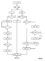
- the regulation method implemented by the adapted means of the compartment comprises a first phase ( Figure 6A ) to verify the environmental conditions while the frequency conversion is not implemented, that is to say that the GFC 205 are still at a standstill.
- the GFC 205 can not be started and stay OFF; if not, they can either be started or stopped.
- Verification of environmental conditions can thus be accompanied by preheating to meet the above criteria.
- the heating device 220 is implemented; once the moisture content falls below the recommended threshold HR 200_min , and after a waiting time t 4 necessary to ensure the evaporation of any water, in particular t 4 > 30 min, the heating 220 is stopped, then the fans GFC 240 are started for a predetermined time t 2 for the GFC is good for operation, for example 15 min: the environmental conditions are then met and the GFC 205 can be put into operation.
- a GFC 205 can operate between 0 ° C (if the water is not frozen) and 45 ° C, under a moisture content up to 95% (if there is not already condensation) .
- the GFC can be started up at once.
- regulation of the temperature is carried out, in particular by virtue of the air extractors 250: the internal temperature T 200 is controlled, and the extractors are used as soon as a temperature value T 200_ref is exceeded , with in this case preferably a linear law increasing the extraction rate with the temperature (see Figure 6B ); although when the GFC 205 are on, condensation can not occur in view of the heat released, it would be possible to also take into account the parameter "degree of humidity" HR.
- the air flow can thus be adjusted to the strictest necessary thanks to the output sensor 260 located in the air flow, which reduces the clogging of the filters 42.
- the threshold T 200_ref is adjusted by depending on the outside temperature T ext .
- T 200_ref is equal to T ext + T 200_gap but T 200_ref can not be less than T 200 _ ref _ min ".
- the humidity level HR 200 is in turn controlled by the heater 220 or the internal fans 240 according to the same internal temperature T 200 in a process similar to that of checking the environmental conditions P1.
- the heater 220 is operated to decrease the humidity level below HR 200_max , for example 85% and stopped at a humidity level of about HR 200_min , for example 75%; if the temperature exceeds 15 ° C, it is the fans 240 which are rotated at a minimum speed V 240_min with the same parameters. It should be noted that we can go from one of the modes to the other, depending on the temperature changes caused by maintaining the RH 200 humidity level or by modifying the external climatic conditions T ext , HR ext .
- the station 10 can meet the criteria of the IP44 to ensure proper operation in a harsh environment, this with a reduced cost, already because the transformers 105 can be of lower power and conventional constitution despite the conditions of use, but also by an extension of the life of components, transformers 105 or GFC 205 which do not undergo accelerated aging since they are used in "normal" conditions, as well as filters 42 which can be changed less often thanks to the regulation of the incoming air flow. Moreover, the energy consumed to control for example the condensation at the GFC 205 is reduced.
- the regulation itself is a robust solution adapted to the particular constraints of the application, with a very fast variation of the dissipated power and a very low time constant, constraints inherent to the load calls on board the powered ships.
- the optimal conditions generated by this system inside the compartments 100, 200 further increase the reliability of the electrical appliances 105, 205 and the station 10 in general, as well as its availability.
Landscapes
- Engineering & Computer Science (AREA)
- Power Engineering (AREA)
- Microelectronics & Electronic Packaging (AREA)
- Physics & Mathematics (AREA)
- Thermal Sciences (AREA)
- Inverter Devices (AREA)
- Air Conditioning Control Device (AREA)
- Devices That Are Associated With Refrigeration Equipment (AREA)
Priority Applications (1)
| Application Number | Priority Date | Filing Date | Title |
|---|---|---|---|
| PL14187786T PL2882052T3 (pl) | 2013-11-18 | 2014-10-06 | Regulacja termiczna przedziału elektrycznego stanowiska portowego do zasilania |
Applications Claiming Priority (2)
| Application Number | Priority Date | Filing Date | Title |
|---|---|---|---|
| FR1361273A FR3013522B1 (fr) | 2013-11-18 | 2013-11-18 | Regulation thermique d'un poste electrique d'alimentation portuaire |
| FR1361274A FR3013523B1 (fr) | 2013-11-18 | 2013-11-18 | Regulation thermique d'un compartiment de conversion de frequence dans un poste electrique d'alimentation portuaire |
Publications (3)
| Publication Number | Publication Date |
|---|---|
| EP2882052A2 true EP2882052A2 (de) | 2015-06-10 |
| EP2882052A3 EP2882052A3 (de) | 2015-08-12 |
| EP2882052B1 EP2882052B1 (de) | 2019-11-27 |
Family
ID=51655665
Family Applications (1)
| Application Number | Title | Priority Date | Filing Date |
|---|---|---|---|
| EP14187786.0A Active EP2882052B1 (de) | 2013-11-18 | 2014-10-06 | Wärmeregulierung des Kastens einer elektrischen Schaltanlage in einem Hafen |
Country Status (5)
| Country | Link |
|---|---|
| EP (1) | EP2882052B1 (de) |
| CN (1) | CN104659693A (de) |
| CA (1) | CA2868089C (de) |
| ES (1) | ES2768329T3 (de) |
| PL (1) | PL2882052T3 (de) |
Cited By (17)
| Publication number | Priority date | Publication date | Assignee | Title |
|---|---|---|---|---|
| CN104979077A (zh) * | 2015-08-03 | 2015-10-14 | 钱国臣 | 一种带有进气控制阀和led照明灯的干式变压器装置 |
| CN104992814A (zh) * | 2015-08-03 | 2015-10-21 | 王磊 | 一种可减震的干式变压器装置 |
| CN104992811A (zh) * | 2015-08-03 | 2015-10-21 | 王磊 | 一种可降噪的干式变压器装置 |
| CN104992824A (zh) * | 2015-08-03 | 2015-10-21 | 王磊 | 一种可调式干式变压器装置 |
| CN104992813A (zh) * | 2015-08-03 | 2015-10-21 | 钱国臣 | 一种带有位置传感器的太阳能干式变压器装置 |
| CN104992816A (zh) * | 2015-08-03 | 2015-10-21 | 张健敏 | 一种带位置传感器且可减震的干式变压器装置 |
| CN105006340A (zh) * | 2015-08-03 | 2015-10-28 | 钱国臣 | 一种带电子控制装置和顶压弹簧的干式变压器装置 |
| CN105071462A (zh) * | 2015-08-03 | 2015-11-18 | 钱国臣 | 一种太阳能供电的干式变压器装置 |
| CN105302209A (zh) * | 2015-11-26 | 2016-02-03 | 国网新疆电力公司信息通信公司 | 电力站用风光发电自动调温系统及其使用方法 |
| JP2017017240A (ja) * | 2015-07-03 | 2017-01-19 | 三菱電機株式会社 | 変圧器 |
| CN106406384A (zh) * | 2016-12-24 | 2017-02-15 | 福州华光天锐光电科技有限公司 | 用于干式变压器的荧光式光纤温控器 |
| CN108074712A (zh) * | 2016-11-16 | 2018-05-25 | 天津光信光电科技有限公司 | 一种带有抽风装置的互感器 |
| CN108443987A (zh) * | 2018-04-25 | 2018-08-24 | 广州市骊庭智能家居有限公司 | 一种环境护理机 |
| US10522801B2 (en) | 2015-09-11 | 2019-12-31 | Younicos, Inc. | Modular energy storage system |
| CN116845753A (zh) * | 2023-09-01 | 2023-10-03 | 中韶电气股份有限公司 | 一种配电箱 |
| US20240270369A1 (en) * | 2021-06-09 | 2024-08-15 | Trident Bmc Ab | High voltage shore connection system with dual intake |
| CN119134089A (zh) * | 2024-09-11 | 2024-12-13 | 淮阴工学院 | 一种智能化箱式变电站通风系统 |
Families Citing this family (2)
| Publication number | Priority date | Publication date | Assignee | Title |
|---|---|---|---|---|
| CN110416880A (zh) * | 2019-08-20 | 2019-11-05 | 深圳供电局有限公司 | 一种智能融冰及除湿一体的户外电力设备箱 |
| CN112376963A (zh) * | 2020-10-20 | 2021-02-19 | 河钢股份有限公司承德分公司 | 一种发电机组的多功能防护装置 |
Citations (1)
| Publication number | Priority date | Publication date | Assignee | Title |
|---|---|---|---|---|
| FR2972576A1 (fr) | 2011-03-11 | 2012-09-14 | Schneider Electric Ind Sas | Procede de realisation d'une installation de conversion d'energie electrique et installation obtenue par un tel procede |
Family Cites Families (15)
| Publication number | Priority date | Publication date | Assignee | Title |
|---|---|---|---|---|
| JPS57133212U (de) * | 1981-02-13 | 1982-08-19 | ||
| JP3498400B2 (ja) * | 1995-01-20 | 2004-02-16 | 株式会社明電舎 | 配電盤の冷却装置 |
| ATE292365T1 (de) * | 1999-02-03 | 2005-04-15 | Heinz Burn | Modulares schaltschranksystem zur aufnahme elektrischer und elektronischer aggregate |
| DE29901658U1 (de) * | 1999-02-03 | 2000-07-13 | Burn, Heinz, Stüsslingen | Modulares Schaltschranksystem zur Aufnahme elektrischer und elektronischer Aggregate |
| WO2005055384A1 (de) * | 2003-12-04 | 2005-06-16 | Almatec Ag | Schrankartiges gehäuse mit luftkühlung |
| JP4980187B2 (ja) * | 2007-09-25 | 2012-07-18 | 東芝三菱電機産業システム株式会社 | 変圧器盤 |
| FR2972598B1 (fr) * | 2011-03-11 | 2013-11-08 | Schneider Electric Ind Sas | Procede de gestion thermique d'une installation de conversion d'energie electrique et installation pour mise en oeuvre du procede |
| CN102147127B (zh) * | 2011-03-24 | 2013-04-03 | 中国扬子集团滁州扬子空调器有限公司 | 一种密闭式人工光植物工厂的空调系统 |
| DE102011001786A1 (de) * | 2011-04-04 | 2012-10-04 | Woodward Kempen Gmbh | Schaltschrankanordnung einer Vorrichtung zur Erzeugung elektrischer Energie |
| DE102011106632B4 (de) * | 2011-06-17 | 2013-07-04 | Sma Solar Technology Ag | Wechselrichter mit Überwachung des Feuchtezustandes und Betriebsverfahren |
| CN202135041U (zh) * | 2011-06-22 | 2012-02-01 | 中国西电电气股份有限公司 | 一种小型化高压变频器 |
| CN202268639U (zh) * | 2011-10-27 | 2012-06-06 | 伊发控股集团有限公司 | 箱式变电站 |
| CN202495317U (zh) * | 2012-04-02 | 2012-10-17 | 张雪燕 | 一种用于配电变压器的绕组冷却装置 |
| CN202889166U (zh) * | 2012-07-25 | 2013-04-17 | 西门子(上海)电气传动设备有限公司 | 变频器 |
| KR101328069B1 (ko) * | 2013-04-02 | 2013-11-13 | 화인테크 주식회사 | 선박평형수 처리용 정류기의 공기배출부 방수통풍구조 |
-
2014
- 2014-10-06 PL PL14187786T patent/PL2882052T3/pl unknown
- 2014-10-06 EP EP14187786.0A patent/EP2882052B1/de active Active
- 2014-10-06 ES ES14187786T patent/ES2768329T3/es active Active
- 2014-10-28 CA CA2868089A patent/CA2868089C/fr active Active
- 2014-11-14 CN CN201410646193.8A patent/CN104659693A/zh active Pending
Patent Citations (1)
| Publication number | Priority date | Publication date | Assignee | Title |
|---|---|---|---|---|
| FR2972576A1 (fr) | 2011-03-11 | 2012-09-14 | Schneider Electric Ind Sas | Procede de realisation d'une installation de conversion d'energie electrique et installation obtenue par un tel procede |
Cited By (19)
| Publication number | Priority date | Publication date | Assignee | Title |
|---|---|---|---|---|
| JP2017017240A (ja) * | 2015-07-03 | 2017-01-19 | 三菱電機株式会社 | 変圧器 |
| CN104992814A (zh) * | 2015-08-03 | 2015-10-21 | 王磊 | 一种可减震的干式变压器装置 |
| CN104992811A (zh) * | 2015-08-03 | 2015-10-21 | 王磊 | 一种可降噪的干式变压器装置 |
| CN104992824A (zh) * | 2015-08-03 | 2015-10-21 | 王磊 | 一种可调式干式变压器装置 |
| CN104992813A (zh) * | 2015-08-03 | 2015-10-21 | 钱国臣 | 一种带有位置传感器的太阳能干式变压器装置 |
| CN104992816A (zh) * | 2015-08-03 | 2015-10-21 | 张健敏 | 一种带位置传感器且可减震的干式变压器装置 |
| CN105006340A (zh) * | 2015-08-03 | 2015-10-28 | 钱国臣 | 一种带电子控制装置和顶压弹簧的干式变压器装置 |
| CN105071462A (zh) * | 2015-08-03 | 2015-11-18 | 钱国臣 | 一种太阳能供电的干式变压器装置 |
| CN104979077A (zh) * | 2015-08-03 | 2015-10-14 | 钱国臣 | 一种带有进气控制阀和led照明灯的干式变压器装置 |
| CN104979077B (zh) * | 2015-08-03 | 2016-06-08 | 国网山东省电力公司菏泽供电公司 | 一种带有进气控制阀和led照明灯的干式变压器装置 |
| US10522801B2 (en) | 2015-09-11 | 2019-12-31 | Younicos, Inc. | Modular energy storage system |
| CN105302209A (zh) * | 2015-11-26 | 2016-02-03 | 国网新疆电力公司信息通信公司 | 电力站用风光发电自动调温系统及其使用方法 |
| CN108074712A (zh) * | 2016-11-16 | 2018-05-25 | 天津光信光电科技有限公司 | 一种带有抽风装置的互感器 |
| CN106406384A (zh) * | 2016-12-24 | 2017-02-15 | 福州华光天锐光电科技有限公司 | 用于干式变压器的荧光式光纤温控器 |
| CN108443987A (zh) * | 2018-04-25 | 2018-08-24 | 广州市骊庭智能家居有限公司 | 一种环境护理机 |
| US20240270369A1 (en) * | 2021-06-09 | 2024-08-15 | Trident Bmc Ab | High voltage shore connection system with dual intake |
| CN116845753A (zh) * | 2023-09-01 | 2023-10-03 | 中韶电气股份有限公司 | 一种配电箱 |
| CN116845753B (zh) * | 2023-09-01 | 2023-11-07 | 中韶电气股份有限公司 | 一种配电箱 |
| CN119134089A (zh) * | 2024-09-11 | 2024-12-13 | 淮阴工学院 | 一种智能化箱式变电站通风系统 |
Also Published As
| Publication number | Publication date |
|---|---|
| CA2868089C (fr) | 2022-05-31 |
| EP2882052A3 (de) | 2015-08-12 |
| CA2868089A1 (fr) | 2015-05-18 |
| EP2882052B1 (de) | 2019-11-27 |
| PL2882052T3 (pl) | 2020-06-01 |
| CN104659693A (zh) | 2015-05-27 |
| ES2768329T3 (es) | 2020-06-22 |
Similar Documents
| Publication | Publication Date | Title |
|---|---|---|
| EP2882052B1 (de) | Wärmeregulierung des Kastens einer elektrischen Schaltanlage in einem Hafen | |
| EP2004489B1 (de) | Vorrichtung und verfahren zur notstromversorgung an bord eines flugzeugs | |
| EP3956218B1 (de) | Hybridantriebssystem und verfahren zur steuerung eines solchen systems | |
| EP4059760B1 (de) | Wasserstoffspeichersystem und luftfahrzeug mit einem wasserstoffspeichersystem | |
| JP2013219941A (ja) | 再生可能エネルギー利用発電システムの制御方法及び制御装置 | |
| WO2018051003A1 (fr) | Procede et systeme d'alimentation d'une charge electrique dans un aeronef | |
| FR3013522A1 (fr) | Regulation thermique d'un poste electrique d'alimentation portuaire | |
| JP6590938B2 (ja) | 風力発電装置の運転方法 | |
| FR3013523A1 (fr) | Regulation thermique d'un compartiment de conversion de frequence dans un poste electrique d'alimentation portuaire | |
| WO2020074812A1 (fr) | Réseau d'alimentation électrique embarqué d'un aéronef à propulsion électrique | |
| EP3843263A1 (de) | Elektroantriebssystem mit vorwärmfunktion zum schutz seines motors vor kondensation | |
| EP2498588B1 (de) | Verfahren zur thermischen Steuerung einer elektrischen Energieumwandlungsanlage, und Anlage zur Umsetzung dieses Verfahrens | |
| EP3639636B1 (de) | Vorrichtung zur kühlung von avionik-racks mit einem wärmeübertragungsfluid | |
| FR3071179B1 (fr) | Refroidissement de secours de presse isostatique a chaud | |
| EP3940318B1 (de) | Anlage zur produktion von kunstschnee | |
| FR2648192A1 (fr) | Soufflerie pour structure gonflable et son procede de regulation de fonctionnement | |
| WO2019229390A1 (fr) | Système de synchronisation de sources d'énergie couplées d'un aéronef | |
| WO2015079155A1 (fr) | Procede et systeme pour la production optimisee d'energie non propulsive | |
| CA3103749A1 (fr) | Installation de rebours mobile | |
| EP2282136B1 (de) | Kontrollierte mechanische Be- und Entlüftungsanlage eines Gebäudes | |
| WO2025242622A1 (fr) | Systeme de gestion de la securite d'une batterie et procede associe | |
| FR2706228A1 (fr) | Procédé et dispositif de régulation de l'alimentation d'un moteur électrique asynchrone. | |
| EP3243271B1 (de) | Vorrichtung zur steuerung eines wechselstromgenerators eines kraftfahrzeugs und entsprechender wechselstromgenerator | |
| WO2014020241A2 (fr) | Installation de production d'energie | |
| FR3064128A1 (fr) | Dispositif moteur |
Legal Events
| Date | Code | Title | Description |
|---|---|---|---|
| PUAI | Public reference made under article 153(3) epc to a published international application that has entered the european phase |
Free format text: ORIGINAL CODE: 0009012 |
|
| 17P | Request for examination filed |
Effective date: 20141006 |
|
| AK | Designated contracting states |
Kind code of ref document: A2 Designated state(s): AL AT BE BG CH CY CZ DE DK EE ES FI FR GB GR HR HU IE IS IT LI LT LU LV MC MK MT NL NO PL PT RO RS SE SI SK SM TR |
|
| AX | Request for extension of the european patent |
Extension state: BA ME |
|
| PUAL | Search report despatched |
Free format text: ORIGINAL CODE: 0009013 |
|
| AK | Designated contracting states |
Kind code of ref document: A3 Designated state(s): AL AT BE BG CH CY CZ DE DK EE ES FI FR GB GR HR HU IE IS IT LI LT LU LV MC MK MT NL NO PL PT RO RS SE SI SK SM TR |
|
| AX | Request for extension of the european patent |
Extension state: BA ME |
|
| RIC1 | Information provided on ipc code assigned before grant |
Ipc: H01F 27/08 20060101ALN20150706BHEP Ipc: H05K 7/20 20060101ALN20150706BHEP Ipc: H02M 7/00 20060101ALN20150706BHEP Ipc: H02B 7/06 20060101ALN20150706BHEP Ipc: H02B 1/56 20060101AFI20150706BHEP |
|
| R17P | Request for examination filed (corrected) |
Effective date: 20150910 |
|
| RBV | Designated contracting states (corrected) |
Designated state(s): AL AT BE BG CH CY CZ DE DK EE ES FI FR GB GR HR HU IE IS IT LI LT LU LV MC MK MT NL NO PL PT RO RS SE SI SK SM TR |
|
| STAA | Information on the status of an ep patent application or granted ep patent |
Free format text: STATUS: EXAMINATION IS IN PROGRESS |
|
| 17Q | First examination report despatched |
Effective date: 20171010 |
|
| RIC1 | Information provided on ipc code assigned before grant |
Ipc: H05K 7/20 20060101ALN20190318BHEP Ipc: H02M 7/00 20060101ALN20190318BHEP Ipc: H01F 27/08 20060101ALN20190318BHEP Ipc: H02B 1/56 20060101AFI20190318BHEP Ipc: H02B 7/06 20060101ALN20190318BHEP |
|
| RIC1 | Information provided on ipc code assigned before grant |
Ipc: H01F 27/08 20060101ALN20190326BHEP Ipc: H05K 7/20 20060101ALN20190326BHEP Ipc: H02B 7/06 20060101ALN20190326BHEP Ipc: H02B 1/56 20060101AFI20190326BHEP Ipc: H02M 7/00 20060101ALN20190326BHEP |
|
| GRAP | Despatch of communication of intention to grant a patent |
Free format text: ORIGINAL CODE: EPIDOSNIGR1 |
|
| STAA | Information on the status of an ep patent application or granted ep patent |
Free format text: STATUS: GRANT OF PATENT IS INTENDED |
|
| RIC1 | Information provided on ipc code assigned before grant |
Ipc: H02B 1/56 20060101AFI20190411BHEP Ipc: H02M 7/00 20060101ALN20190411BHEP Ipc: H02B 7/06 20060101ALN20190411BHEP Ipc: H05K 7/20 20060101ALN20190411BHEP Ipc: H01F 27/08 20060101ALN20190411BHEP |
|
| INTG | Intention to grant announced |
Effective date: 20190514 |
|
| GRAS | Grant fee paid |
Free format text: ORIGINAL CODE: EPIDOSNIGR3 |
|
| GRAA | (expected) grant |
Free format text: ORIGINAL CODE: 0009210 |
|
| STAA | Information on the status of an ep patent application or granted ep patent |
Free format text: STATUS: THE PATENT HAS BEEN GRANTED |
|
| AK | Designated contracting states |
Kind code of ref document: B1 Designated state(s): AL AT BE BG CH CY CZ DE DK EE ES FI FR GB GR HR HU IE IS IT LI LT LU LV MC MK MT NL NO PL PT RO RS SE SI SK SM TR |
|
| REG | Reference to a national code |
Ref country code: GB Ref legal event code: FG4D Free format text: NOT ENGLISH |
|
| REG | Reference to a national code |
Ref country code: CH Ref legal event code: EP |
|
| REG | Reference to a national code |
Ref country code: AT Ref legal event code: REF Ref document number: 1207795 Country of ref document: AT Kind code of ref document: T Effective date: 20191215 |
|
| REG | Reference to a national code |
Ref country code: DE Ref legal event code: R096 Ref document number: 602014057402 Country of ref document: DE |
|
| REG | Reference to a national code |
Ref country code: IE Ref legal event code: FG4D Free format text: LANGUAGE OF EP DOCUMENT: FRENCH |
|
| REG | Reference to a national code |
Ref country code: NO Ref legal event code: T2 Effective date: 20191127 |
|
| REG | Reference to a national code |
Ref country code: LT Ref legal event code: MG4D |
|
| PG25 | Lapsed in a contracting state [announced via postgrant information from national office to epo] |
Ref country code: FI Free format text: LAPSE BECAUSE OF FAILURE TO SUBMIT A TRANSLATION OF THE DESCRIPTION OR TO PAY THE FEE WITHIN THE PRESCRIBED TIME-LIMIT Effective date: 20191127 Ref country code: BG Free format text: LAPSE BECAUSE OF FAILURE TO SUBMIT A TRANSLATION OF THE DESCRIPTION OR TO PAY THE FEE WITHIN THE PRESCRIBED TIME-LIMIT Effective date: 20200227 Ref country code: GR Free format text: LAPSE BECAUSE OF FAILURE TO SUBMIT A TRANSLATION OF THE DESCRIPTION OR TO PAY THE FEE WITHIN THE PRESCRIBED TIME-LIMIT Effective date: 20200228 Ref country code: LV Free format text: LAPSE BECAUSE OF FAILURE TO SUBMIT A TRANSLATION OF THE DESCRIPTION OR TO PAY THE FEE WITHIN THE PRESCRIBED TIME-LIMIT Effective date: 20191127 Ref country code: SE Free format text: LAPSE BECAUSE OF FAILURE TO SUBMIT A TRANSLATION OF THE DESCRIPTION OR TO PAY THE FEE WITHIN THE PRESCRIBED TIME-LIMIT Effective date: 20191127 Ref country code: LT Free format text: LAPSE BECAUSE OF FAILURE TO SUBMIT A TRANSLATION OF THE DESCRIPTION OR TO PAY THE FEE WITHIN THE PRESCRIBED TIME-LIMIT Effective date: 20191127 |
|
| REG | Reference to a national code |
Ref country code: NL Ref legal event code: FP |
|
| PG25 | Lapsed in a contracting state [announced via postgrant information from national office to epo] |
Ref country code: HR Free format text: LAPSE BECAUSE OF FAILURE TO SUBMIT A TRANSLATION OF THE DESCRIPTION OR TO PAY THE FEE WITHIN THE PRESCRIBED TIME-LIMIT Effective date: 20191127 Ref country code: RS Free format text: LAPSE BECAUSE OF FAILURE TO SUBMIT A TRANSLATION OF THE DESCRIPTION OR TO PAY THE FEE WITHIN THE PRESCRIBED TIME-LIMIT Effective date: 20191127 Ref country code: IS Free format text: LAPSE BECAUSE OF FAILURE TO SUBMIT A TRANSLATION OF THE DESCRIPTION OR TO PAY THE FEE WITHIN THE PRESCRIBED TIME-LIMIT Effective date: 20200327 |
|
| REG | Reference to a national code |
Ref country code: ES Ref legal event code: FG2A Ref document number: 2768329 Country of ref document: ES Kind code of ref document: T3 Effective date: 20200622 |
|
| PG25 | Lapsed in a contracting state [announced via postgrant information from national office to epo] |
Ref country code: AL Free format text: LAPSE BECAUSE OF FAILURE TO SUBMIT A TRANSLATION OF THE DESCRIPTION OR TO PAY THE FEE WITHIN THE PRESCRIBED TIME-LIMIT Effective date: 20191127 |
|
| PG25 | Lapsed in a contracting state [announced via postgrant information from national office to epo] |
Ref country code: EE Free format text: LAPSE BECAUSE OF FAILURE TO SUBMIT A TRANSLATION OF THE DESCRIPTION OR TO PAY THE FEE WITHIN THE PRESCRIBED TIME-LIMIT Effective date: 20191127 Ref country code: PT Free format text: LAPSE BECAUSE OF FAILURE TO SUBMIT A TRANSLATION OF THE DESCRIPTION OR TO PAY THE FEE WITHIN THE PRESCRIBED TIME-LIMIT Effective date: 20200419 Ref country code: DK Free format text: LAPSE BECAUSE OF FAILURE TO SUBMIT A TRANSLATION OF THE DESCRIPTION OR TO PAY THE FEE WITHIN THE PRESCRIBED TIME-LIMIT Effective date: 20191127 Ref country code: CZ Free format text: LAPSE BECAUSE OF FAILURE TO SUBMIT A TRANSLATION OF THE DESCRIPTION OR TO PAY THE FEE WITHIN THE PRESCRIBED TIME-LIMIT Effective date: 20191127 Ref country code: RO Free format text: LAPSE BECAUSE OF FAILURE TO SUBMIT A TRANSLATION OF THE DESCRIPTION OR TO PAY THE FEE WITHIN THE PRESCRIBED TIME-LIMIT Effective date: 20191127 |
|
| REG | Reference to a national code |
Ref country code: DE Ref legal event code: R097 Ref document number: 602014057402 Country of ref document: DE |
|
| PG25 | Lapsed in a contracting state [announced via postgrant information from national office to epo] |
Ref country code: SM Free format text: LAPSE BECAUSE OF FAILURE TO SUBMIT A TRANSLATION OF THE DESCRIPTION OR TO PAY THE FEE WITHIN THE PRESCRIBED TIME-LIMIT Effective date: 20191127 Ref country code: SK Free format text: LAPSE BECAUSE OF FAILURE TO SUBMIT A TRANSLATION OF THE DESCRIPTION OR TO PAY THE FEE WITHIN THE PRESCRIBED TIME-LIMIT Effective date: 20191127 |
|
| REG | Reference to a national code |
Ref country code: AT Ref legal event code: MK05 Ref document number: 1207795 Country of ref document: AT Kind code of ref document: T Effective date: 20191127 |
|
| PLBE | No opposition filed within time limit |
Free format text: ORIGINAL CODE: 0009261 |
|
| STAA | Information on the status of an ep patent application or granted ep patent |
Free format text: STATUS: NO OPPOSITION FILED WITHIN TIME LIMIT |
|
| 26N | No opposition filed |
Effective date: 20200828 |
|
| PG25 | Lapsed in a contracting state [announced via postgrant information from national office to epo] |
Ref country code: AT Free format text: LAPSE BECAUSE OF FAILURE TO SUBMIT A TRANSLATION OF THE DESCRIPTION OR TO PAY THE FEE WITHIN THE PRESCRIBED TIME-LIMIT Effective date: 20191127 Ref country code: SI Free format text: LAPSE BECAUSE OF FAILURE TO SUBMIT A TRANSLATION OF THE DESCRIPTION OR TO PAY THE FEE WITHIN THE PRESCRIBED TIME-LIMIT Effective date: 20191127 |
|
| PG25 | Lapsed in a contracting state [announced via postgrant information from national office to epo] |
Ref country code: IT Free format text: LAPSE BECAUSE OF FAILURE TO SUBMIT A TRANSLATION OF THE DESCRIPTION OR TO PAY THE FEE WITHIN THE PRESCRIBED TIME-LIMIT Effective date: 20191127 |
|
| REG | Reference to a national code |
Ref country code: DE Ref legal event code: R119 Ref document number: 602014057402 Country of ref document: DE |
|
| REG | Reference to a national code |
Ref country code: CH Ref legal event code: PL |
|
| PG25 | Lapsed in a contracting state [announced via postgrant information from national office to epo] |
Ref country code: MC Free format text: LAPSE BECAUSE OF FAILURE TO SUBMIT A TRANSLATION OF THE DESCRIPTION OR TO PAY THE FEE WITHIN THE PRESCRIBED TIME-LIMIT Effective date: 20191127 Ref country code: LU Free format text: LAPSE BECAUSE OF NON-PAYMENT OF DUE FEES Effective date: 20201006 |
|
| PG25 | Lapsed in a contracting state [announced via postgrant information from national office to epo] |
Ref country code: DE Free format text: LAPSE BECAUSE OF NON-PAYMENT OF DUE FEES Effective date: 20210501 |
|
| PG25 | Lapsed in a contracting state [announced via postgrant information from national office to epo] |
Ref country code: CH Free format text: LAPSE BECAUSE OF NON-PAYMENT OF DUE FEES Effective date: 20201031 Ref country code: LI Free format text: LAPSE BECAUSE OF NON-PAYMENT OF DUE FEES Effective date: 20201031 |
|
| PG25 | Lapsed in a contracting state [announced via postgrant information from national office to epo] |
Ref country code: IE Free format text: LAPSE BECAUSE OF NON-PAYMENT OF DUE FEES Effective date: 20201006 |
|
| PG25 | Lapsed in a contracting state [announced via postgrant information from national office to epo] |
Ref country code: TR Free format text: LAPSE BECAUSE OF FAILURE TO SUBMIT A TRANSLATION OF THE DESCRIPTION OR TO PAY THE FEE WITHIN THE PRESCRIBED TIME-LIMIT Effective date: 20191127 Ref country code: MT Free format text: LAPSE BECAUSE OF FAILURE TO SUBMIT A TRANSLATION OF THE DESCRIPTION OR TO PAY THE FEE WITHIN THE PRESCRIBED TIME-LIMIT Effective date: 20191127 Ref country code: CY Free format text: LAPSE BECAUSE OF FAILURE TO SUBMIT A TRANSLATION OF THE DESCRIPTION OR TO PAY THE FEE WITHIN THE PRESCRIBED TIME-LIMIT Effective date: 20191127 |
|
| PG25 | Lapsed in a contracting state [announced via postgrant information from national office to epo] |
Ref country code: MK Free format text: LAPSE BECAUSE OF FAILURE TO SUBMIT A TRANSLATION OF THE DESCRIPTION OR TO PAY THE FEE WITHIN THE PRESCRIBED TIME-LIMIT Effective date: 20191127 |
|
| PGFP | Annual fee paid to national office [announced via postgrant information from national office to epo] |
Ref country code: NL Payment date: 20241023 Year of fee payment: 11 |
|
| PGFP | Annual fee paid to national office [announced via postgrant information from national office to epo] |
Ref country code: BE Payment date: 20241023 Year of fee payment: 11 |
|
| PGFP | Annual fee paid to national office [announced via postgrant information from national office to epo] |
Ref country code: ES Payment date: 20241118 Year of fee payment: 11 |
|
| PGFP | Annual fee paid to national office [announced via postgrant information from national office to epo] |
Ref country code: PL Payment date: 20250926 Year of fee payment: 12 |
|
| PGFP | Annual fee paid to national office [announced via postgrant information from national office to epo] |
Ref country code: GB Payment date: 20251017 Year of fee payment: 12 |
|
| PGFP | Annual fee paid to national office [announced via postgrant information from national office to epo] |
Ref country code: NO Payment date: 20251022 Year of fee payment: 12 |
|
| PGFP | Annual fee paid to national office [announced via postgrant information from national office to epo] |
Ref country code: FR Payment date: 20251030 Year of fee payment: 12 |