EP4059760B1 - Wasserstoffspeichersystem und luftfahrzeug mit einem wasserstoffspeichersystem - Google Patents
Wasserstoffspeichersystem und luftfahrzeug mit einem wasserstoffspeichersystem Download PDFInfo
- Publication number
- EP4059760B1 EP4059760B1 EP22160689.0A EP22160689A EP4059760B1 EP 4059760 B1 EP4059760 B1 EP 4059760B1 EP 22160689 A EP22160689 A EP 22160689A EP 4059760 B1 EP4059760 B1 EP 4059760B1
- Authority
- EP
- European Patent Office
- Prior art keywords
- hydrogen
- aircraft
- tank
- fuel cell
- electrical
- Prior art date
- Legal status (The legal status is an assumption and is not a legal conclusion. Google has not performed a legal analysis and makes no representation as to the accuracy of the status listed.)
- Active
Links
Images




Classifications
-
- B—PERFORMING OPERATIONS; TRANSPORTING
- B60—VEHICLES IN GENERAL
- B60L—PROPULSION OF ELECTRICALLY-PROPELLED VEHICLES; SUPPLYING ELECTRIC POWER FOR AUXILIARY EQUIPMENT OF ELECTRICALLY-PROPELLED VEHICLES; ELECTRODYNAMIC BRAKE SYSTEMS FOR VEHICLES IN GENERAL; MAGNETIC SUSPENSION OR LEVITATION FOR VEHICLES; MONITORING OPERATING VARIABLES OF ELECTRICALLY-PROPELLED VEHICLES; ELECTRIC SAFETY DEVICES FOR ELECTRICALLY-PROPELLED VEHICLES
- B60L3/00—Electric devices on electrically-propelled vehicles for safety purposes; Monitoring operating variables, e.g. speed, deceleration or energy consumption
- B60L3/0092—Electric devices on electrically-propelled vehicles for safety purposes; Monitoring operating variables, e.g. speed, deceleration or energy consumption with use of redundant elements for safety purposes
-
- B—PERFORMING OPERATIONS; TRANSPORTING
- B60—VEHICLES IN GENERAL
- B60L—PROPULSION OF ELECTRICALLY-PROPELLED VEHICLES; SUPPLYING ELECTRIC POWER FOR AUXILIARY EQUIPMENT OF ELECTRICALLY-PROPELLED VEHICLES; ELECTRODYNAMIC BRAKE SYSTEMS FOR VEHICLES IN GENERAL; MAGNETIC SUSPENSION OR LEVITATION FOR VEHICLES; MONITORING OPERATING VARIABLES OF ELECTRICALLY-PROPELLED VEHICLES; ELECTRIC SAFETY DEVICES FOR ELECTRICALLY-PROPELLED VEHICLES
- B60L1/00—Supplying electric power to auxiliary equipment of vehicles
-
- B—PERFORMING OPERATIONS; TRANSPORTING
- B60—VEHICLES IN GENERAL
- B60L—PROPULSION OF ELECTRICALLY-PROPELLED VEHICLES; SUPPLYING ELECTRIC POWER FOR AUXILIARY EQUIPMENT OF ELECTRICALLY-PROPELLED VEHICLES; ELECTRODYNAMIC BRAKE SYSTEMS FOR VEHICLES IN GENERAL; MAGNETIC SUSPENSION OR LEVITATION FOR VEHICLES; MONITORING OPERATING VARIABLES OF ELECTRICALLY-PROPELLED VEHICLES; ELECTRIC SAFETY DEVICES FOR ELECTRICALLY-PROPELLED VEHICLES
- B60L1/00—Supplying electric power to auxiliary equipment of vehicles
- B60L1/02—Supplying electric power to auxiliary equipment of vehicles to electric heating circuits
-
- B—PERFORMING OPERATIONS; TRANSPORTING
- B60—VEHICLES IN GENERAL
- B60L—PROPULSION OF ELECTRICALLY-PROPELLED VEHICLES; SUPPLYING ELECTRIC POWER FOR AUXILIARY EQUIPMENT OF ELECTRICALLY-PROPELLED VEHICLES; ELECTRODYNAMIC BRAKE SYSTEMS FOR VEHICLES IN GENERAL; MAGNETIC SUSPENSION OR LEVITATION FOR VEHICLES; MONITORING OPERATING VARIABLES OF ELECTRICALLY-PROPELLED VEHICLES; ELECTRIC SAFETY DEVICES FOR ELECTRICALLY-PROPELLED VEHICLES
- B60L50/00—Electric propulsion with power supplied within the vehicle
- B60L50/50—Electric propulsion with power supplied within the vehicle using propulsion power supplied by batteries or fuel cells
- B60L50/70—Electric propulsion with power supplied within the vehicle using propulsion power supplied by batteries or fuel cells using power supplied by fuel cells
-
- B—PERFORMING OPERATIONS; TRANSPORTING
- B60—VEHICLES IN GENERAL
- B60L—PROPULSION OF ELECTRICALLY-PROPELLED VEHICLES; SUPPLYING ELECTRIC POWER FOR AUXILIARY EQUIPMENT OF ELECTRICALLY-PROPELLED VEHICLES; ELECTRODYNAMIC BRAKE SYSTEMS FOR VEHICLES IN GENERAL; MAGNETIC SUSPENSION OR LEVITATION FOR VEHICLES; MONITORING OPERATING VARIABLES OF ELECTRICALLY-PROPELLED VEHICLES; ELECTRIC SAFETY DEVICES FOR ELECTRICALLY-PROPELLED VEHICLES
- B60L58/00—Methods or circuit arrangements for monitoring or controlling batteries or fuel cells, specially adapted for electric vehicles
- B60L58/30—Methods or circuit arrangements for monitoring or controlling batteries or fuel cells, specially adapted for electric vehicles for monitoring or controlling fuel cells
- B60L58/32—Methods or circuit arrangements for monitoring or controlling batteries or fuel cells, specially adapted for electric vehicles for monitoring or controlling fuel cells for controlling the temperature of fuel cells, e.g. by controlling the electric load
- B60L58/34—Methods or circuit arrangements for monitoring or controlling batteries or fuel cells, specially adapted for electric vehicles for monitoring or controlling fuel cells for controlling the temperature of fuel cells, e.g. by controlling the electric load by heating
-
- B—PERFORMING OPERATIONS; TRANSPORTING
- B64—AIRCRAFT; AVIATION; COSMONAUTICS
- B64D—EQUIPMENT FOR FITTING IN OR TO AIRCRAFT; FLIGHT SUITS; PARACHUTES; ARRANGEMENT OR MOUNTING OF POWER PLANTS OR PROPULSION TRANSMISSIONS IN AIRCRAFT
- B64D27/00—Arrangement or mounting of power plants in aircraft; Aircraft characterised by the type or position of power plants
- B64D27/02—Aircraft characterised by the type or position of power plants
- B64D27/026—Aircraft characterised by the type or position of power plants comprising different types of power plants, e.g. combination of a piston engine and a gas-turbine
-
- B—PERFORMING OPERATIONS; TRANSPORTING
- B64—AIRCRAFT; AVIATION; COSMONAUTICS
- B64D—EQUIPMENT FOR FITTING IN OR TO AIRCRAFT; FLIGHT SUITS; PARACHUTES; ARRANGEMENT OR MOUNTING OF POWER PLANTS OR PROPULSION TRANSMISSIONS IN AIRCRAFT
- B64D27/00—Arrangement or mounting of power plants in aircraft; Aircraft characterised by the type or position of power plants
- B64D27/02—Aircraft characterised by the type or position of power plants
- B64D27/24—Aircraft characterised by the type or position of power plants using steam or spring force
-
- B—PERFORMING OPERATIONS; TRANSPORTING
- B64—AIRCRAFT; AVIATION; COSMONAUTICS
- B64D—EQUIPMENT FOR FITTING IN OR TO AIRCRAFT; FLIGHT SUITS; PARACHUTES; ARRANGEMENT OR MOUNTING OF POWER PLANTS OR PROPULSION TRANSMISSIONS IN AIRCRAFT
- B64D27/00—Arrangement or mounting of power plants in aircraft; Aircraft characterised by the type or position of power plants
- B64D27/02—Aircraft characterised by the type or position of power plants
- B64D27/30—Aircraft characterised by electric power plants
- B64D27/34—All-electric aircraft
-
- B—PERFORMING OPERATIONS; TRANSPORTING
- B64—AIRCRAFT; AVIATION; COSMONAUTICS
- B64D—EQUIPMENT FOR FITTING IN OR TO AIRCRAFT; FLIGHT SUITS; PARACHUTES; ARRANGEMENT OR MOUNTING OF POWER PLANTS OR PROPULSION TRANSMISSIONS IN AIRCRAFT
- B64D27/00—Arrangement or mounting of power plants in aircraft; Aircraft characterised by the type or position of power plants
- B64D27/02—Aircraft characterised by the type or position of power plants
- B64D27/30—Aircraft characterised by electric power plants
- B64D27/35—Arrangements for on-board electric energy production, distribution, recovery or storage
- B64D27/355—Arrangements for on-board electric energy production, distribution, recovery or storage using fuel cells
-
- B—PERFORMING OPERATIONS; TRANSPORTING
- B64—AIRCRAFT; AVIATION; COSMONAUTICS
- B64D—EQUIPMENT FOR FITTING IN OR TO AIRCRAFT; FLIGHT SUITS; PARACHUTES; ARRANGEMENT OR MOUNTING OF POWER PLANTS OR PROPULSION TRANSMISSIONS IN AIRCRAFT
- B64D37/00—Arrangements in connection with fuel supply for power plant
- B64D37/30—Fuel systems for specific fuels
-
- B—PERFORMING OPERATIONS; TRANSPORTING
- B64—AIRCRAFT; AVIATION; COSMONAUTICS
- B64D—EQUIPMENT FOR FITTING IN OR TO AIRCRAFT; FLIGHT SUITS; PARACHUTES; ARRANGEMENT OR MOUNTING OF POWER PLANTS OR PROPULSION TRANSMISSIONS IN AIRCRAFT
- B64D37/00—Arrangements in connection with fuel supply for power plant
- B64D37/32—Safety measures not otherwise provided for, e.g. preventing explosive conditions
-
- B—PERFORMING OPERATIONS; TRANSPORTING
- B64—AIRCRAFT; AVIATION; COSMONAUTICS
- B64D—EQUIPMENT FOR FITTING IN OR TO AIRCRAFT; FLIGHT SUITS; PARACHUTES; ARRANGEMENT OR MOUNTING OF POWER PLANTS OR PROPULSION TRANSMISSIONS IN AIRCRAFT
- B64D37/00—Arrangements in connection with fuel supply for power plant
- B64D37/34—Conditioning fuel, e.g. heating
-
- B—PERFORMING OPERATIONS; TRANSPORTING
- B64—AIRCRAFT; AVIATION; COSMONAUTICS
- B64D—EQUIPMENT FOR FITTING IN OR TO AIRCRAFT; FLIGHT SUITS; PARACHUTES; ARRANGEMENT OR MOUNTING OF POWER PLANTS OR PROPULSION TRANSMISSIONS IN AIRCRAFT
- B64D41/00—Power installations for auxiliary purposes
-
- H—ELECTRICITY
- H01—ELECTRIC ELEMENTS
- H01M—PROCESSES OR MEANS, e.g. BATTERIES, FOR THE DIRECT CONVERSION OF CHEMICAL ENERGY INTO ELECTRICAL ENERGY
- H01M8/00—Fuel cells; Manufacture thereof
- H01M8/04—Auxiliary arrangements, e.g. for control of pressure or for circulation of fluids
- H01M8/04082—Arrangements for control of reactant parameters, e.g. pressure or concentration
- H01M8/04089—Arrangements for control of reactant parameters, e.g. pressure or concentration of gaseous reactants
-
- H—ELECTRICITY
- H01—ELECTRIC ELEMENTS
- H01M—PROCESSES OR MEANS, e.g. BATTERIES, FOR THE DIRECT CONVERSION OF CHEMICAL ENERGY INTO ELECTRICAL ENERGY
- H01M8/00—Fuel cells; Manufacture thereof
- H01M8/04—Auxiliary arrangements, e.g. for control of pressure or for circulation of fluids
- H01M8/04082—Arrangements for control of reactant parameters, e.g. pressure or concentration
- H01M8/04201—Reactant storage and supply, e.g. means for feeding, pipes
-
- H—ELECTRICITY
- H01—ELECTRIC ELEMENTS
- H01M—PROCESSES OR MEANS, e.g. BATTERIES, FOR THE DIRECT CONVERSION OF CHEMICAL ENERGY INTO ELECTRICAL ENERGY
- H01M8/00—Fuel cells; Manufacture thereof
- H01M8/04—Auxiliary arrangements, e.g. for control of pressure or for circulation of fluids
- H01M8/04298—Processes for controlling fuel cells or fuel cell systems
- H01M8/04313—Processes for controlling fuel cells or fuel cell systems characterised by the detection or assessment of variables; characterised by the detection or assessment of failure or abnormal function
- H01M8/0438—Pressure; Ambient pressure; Flow
- H01M8/04425—Pressure; Ambient pressure; Flow at auxiliary devices, e.g. reformers, compressors, burners
-
- H—ELECTRICITY
- H01—ELECTRIC ELEMENTS
- H01M—PROCESSES OR MEANS, e.g. BATTERIES, FOR THE DIRECT CONVERSION OF CHEMICAL ENERGY INTO ELECTRICAL ENERGY
- H01M8/00—Fuel cells; Manufacture thereof
- H01M8/04—Auxiliary arrangements, e.g. for control of pressure or for circulation of fluids
- H01M8/04298—Processes for controlling fuel cells or fuel cell systems
- H01M8/04694—Processes for controlling fuel cells or fuel cell systems characterised by variables to be controlled
- H01M8/04746—Pressure; Flow
- H01M8/04776—Pressure; Flow at auxiliary devices, e.g. reformer, compressor, burner
-
- H—ELECTRICITY
- H01—ELECTRIC ELEMENTS
- H01M—PROCESSES OR MEANS, e.g. BATTERIES, FOR THE DIRECT CONVERSION OF CHEMICAL ENERGY INTO ELECTRICAL ENERGY
- H01M8/00—Fuel cells; Manufacture thereof
- H01M8/24—Grouping of fuel cells, e.g. stacking of fuel cells
- H01M8/249—Grouping of fuel cells, e.g. stacking of fuel cells comprising two or more groupings of fuel cells, e.g. modular assemblies
-
- B—PERFORMING OPERATIONS; TRANSPORTING
- B60—VEHICLES IN GENERAL
- B60L—PROPULSION OF ELECTRICALLY-PROPELLED VEHICLES; SUPPLYING ELECTRIC POWER FOR AUXILIARY EQUIPMENT OF ELECTRICALLY-PROPELLED VEHICLES; ELECTRODYNAMIC BRAKE SYSTEMS FOR VEHICLES IN GENERAL; MAGNETIC SUSPENSION OR LEVITATION FOR VEHICLES; MONITORING OPERATING VARIABLES OF ELECTRICALLY-PROPELLED VEHICLES; ELECTRIC SAFETY DEVICES FOR ELECTRICALLY-PROPELLED VEHICLES
- B60L2200/00—Type of vehicles
- B60L2200/10—Air crafts
-
- B—PERFORMING OPERATIONS; TRANSPORTING
- B64—AIRCRAFT; AVIATION; COSMONAUTICS
- B64D—EQUIPMENT FOR FITTING IN OR TO AIRCRAFT; FLIGHT SUITS; PARACHUTES; ARRANGEMENT OR MOUNTING OF POWER PLANTS OR PROPULSION TRANSMISSIONS IN AIRCRAFT
- B64D41/00—Power installations for auxiliary purposes
- B64D2041/005—Fuel cells
-
- H—ELECTRICITY
- H01—ELECTRIC ELEMENTS
- H01M—PROCESSES OR MEANS, e.g. BATTERIES, FOR THE DIRECT CONVERSION OF CHEMICAL ENERGY INTO ELECTRICAL ENERGY
- H01M2250/00—Fuel cells for particular applications; Specific features of fuel cell system
- H01M2250/20—Fuel cells in motive systems, e.g. vehicle, ship, plane
-
- Y—GENERAL TAGGING OF NEW TECHNOLOGICAL DEVELOPMENTS; GENERAL TAGGING OF CROSS-SECTIONAL TECHNOLOGIES SPANNING OVER SEVERAL SECTIONS OF THE IPC; TECHNICAL SUBJECTS COVERED BY FORMER USPC CROSS-REFERENCE ART COLLECTIONS [XRACs] AND DIGESTS
- Y02—TECHNOLOGIES OR APPLICATIONS FOR MITIGATION OR ADAPTATION AGAINST CLIMATE CHANGE
- Y02T—CLIMATE CHANGE MITIGATION TECHNOLOGIES RELATED TO TRANSPORTATION
- Y02T90/00—Enabling technologies or technologies with a potential or indirect contribution to GHG emissions mitigation
- Y02T90/40—Application of hydrogen technology to transportation, e.g. using fuel cells
Definitions
- the invention relates to the field of hydrogen storage and more particularly to its application to aircraft using an electric propulsion system powered by hydrogen.
- a liquid hydrogen tank for supplying hydrogen to fuel cells or a hydrogen combustion propulsion engine.
- the hydrogen must be kept at a very low temperature, of the order of -253°C.
- the hydrogen tank is provided with very high-performance thermal insulation.
- some of the hydrogen is caused to evaporate in the tank.
- hydrogen from the tank is used to ensure the operation of the aircraft, in particular its propulsion, this evaporation phenomenon is not a problem since the hydrogen thus evaporated is used on board the aircraft, for example to supply fuel cells or a hydrogen combustion engine.
- a second solution could be to power the surveillance system using an electrical source located on the ground, for example a "ground power unit" at the airport where the aircraft is parked.
- an electrical source located on the ground, for example a "ground power unit” at the airport where the aircraft is parked.
- this solution would make the aircraft dependent on the means available on the ground, which could lead to situations that would be difficult to manage if an airport did not have a suitable electrical source.
- the document US2016/159492A1 describes a system comprising a fuel cell supplied with hydrogen from a hydrogen tank.
- a hybrid regulator is connected in series to a hydrogen line between the hydrogen tank and the fuel cell.
- This hybrid regulator whose inlet is connected to the hydrogen tank, makes it possible to regulate the pressure of the hydrogen at its outlet, connected to the fuel cell.
- the hybrid regulator comprises a linear actuator making it possible to adjust the value of the pressure of the hydrogen at its outlet.
- the hybrid regulator regulates the pressure of the hydrogen at its outlet independently of the pressure of the hydrogen at its inlet, corresponding to the pressure of the hydrogen in the tank. Consequently, the hybrid regulator is of no use in limiting the pressure inside the hydrogen tank.
- the present invention aims in particular to provide a solution to this problem. It relates to an assembly comprising an aircraft and a hydrogen storage system, in accordance with claim 1.
- the fuel cell since the fuel cell is permanently connected to the hydrogen tank, the fuel cell is continuously supplied with hydrogen as long as there is hydrogen in the tank. Consequently, as long as there is hydrogen in the tank, the fuel cell produces electricity to power the processing unit. This makes it possible to power the hydrogen evaporation control system autonomously and therefore guarantee its operation as long as there is hydrogen in the tank. In addition, consuming hydrogen from the tank to power the fuel cell increases the time before tank depressurization, by controlling the valve, is necessary.
- the hydrogen storage system 10 shown in the Figure 1 comprises a hydrogen tank 12 (labeled “H2” in the figure), a fuel cell 14 (labeled “FC” in the figure), a processing unit 16 (labeled "Proc” in the figure), as well as a pipe 18 on which a controllable valve 22 is mounted in series.
- a first end of the pipe 18 is connected to the hydrogen tank 12.
- a second end of the pipe 18 is provided to discharge hydrogen from the hydrogen tank 12 into the atmosphere when the valve 22 is open.
- the fuel cell 14 is permanently connected to the hydrogen tank 12 by a pipe 21, so as to allow the production of electricity by the fuel cell 14 as long as the tank 12 contains hydrogen.
- the processing unit 16 is connected to the fuel cell 14 by an electrical circuit 24 provided to enable the processing unit 16 to be supplied with electricity by the fuel cell 14.
- the processing unit 16 is also connected at the output to a control input of the valve 22, by a connection 26, so as to enable the processing unit 16 to control the opening or closing of the valve 22.
- the processing unit 16 is also connected at the input to a pressure sensor 25 by a connection 23.
- the pressure sensor 25 is installed so as to enable the pressure of the hydrogen in the hydrogen tank 12 to be measured.
- the pressure sensor 25 is installed in the hydrogen tank 12.
- the pressure sensor 25 is installed in a hydrogen pipe connected to the hydrogen tank.
- the processing unit 16 comprises for example a microprocessor or a microcontroller.
- the hydrogen tank 12 is installed on board an aircraft such as the aircraft 1 shown in the Figure 2
- the hydrogen tank 12 is then connected, for example, to a propulsion system 3 of the aircraft by a pipe 20, such that the propulsion system 3 is supplied with energy by hydrogen from the tank 12.
- the operation of the hydrogen storage system is as indicated below.
- the fuel cell 14 receives hydrogen from the tank via the pipe 21, such that the fuel cell produces electricity continuously. Consequently, the processing unit 16, electrically connected to the fuel cell 14 by the electrical circuit 24, is continuously electrically powered as long as the hydrogen tank 12 contains hydrogen. This ensures the operation of the processing unit 16 as long as the hydrogen tank 12 contains hydrogen.
- the processing unit 16 controls the opening or closing of the valve 22 as a function of the pressure inside the hydrogen tank 12. In one embodiment, the processing unit controls the opening of the valve 22 when said pressure is greater than or equal to a first predetermined pressure threshold and it controls the closing of the valve when the pressure is less than or equal to a second predetermined pressure threshold, less than the first pressure threshold.
- opening the valve 22 allows part of the hydrogen contained in the tank in gaseous form to be evacuated via the pipe 18. This part of the hydrogen is thus released into the atmosphere, which allows the pressure in the hydrogen tank to be reduced. The pressure in the tank thus decreases until it reaches, downwards, the second predetermined pressure threshold.
- the processing unit 16 controls the closing of the valve 22 so as to stop releasing hydrogen into the atmosphere. This operation makes it possible to ensure that the value of the pressure inside the hydrogen tank does not exceed the first predetermined pressure threshold.
- the processing unit uses, for example, as a pressure value, a pressure value acquired from the pressure sensor 25.
- the processing unit monitors the pressure repeatedly, for example over a period of approximately 1 second.
- the value of the first pressure threshold is for example chosen in the interval [5 bars; 25 bars], for example 10 bars
- the value of the second pressure threshold is for example chosen in the interval [5 bars; 10 bars], for example 5 bars.
- the propulsion system 3 when the hydrogen storage system 10 is connected to the propulsion system 3, the propulsion system 3 comprises an engine operating by combustion of hydrogen from the hydrogen storage system 10 via the pipe 20.
- the propulsion system 3 comprises a set of fuel cells 34, electrically connected, by a set of electrical connections 33, to at least one electric motor 32.
- a propulsion propeller 30 is mechanically coupled to the electric motor 32.
- the fuel cells of the set of fuel cells 34 are connected at the input to the hydrogen storage system 10 via the pipe 20.
- the propulsion system 3 further comprises a controller not shown in the Figure 3 .
- the controller controls the hydrogen supply fuel cells of the fuel cell assembly 34, for example by controlling the opening of a valve mounted in series on the pipe 20.
- the fuel cells then produce electricity, thus making it possible to electrically power the motor 32 which then drives the propulsion propeller 30 in rotation.
- the fuel cell 14 of the hydrogen storage system is part of the fuel cell assembly 34 electrically powering the electric motor 32.
- the fuel cell 14 is permanently connected to the hydrogen tank by the pipe 21.
- the other fuel cells of the fuel cell set 34 are supplied with hydrogen by the pipe 20. This hydrogen supply is controlled by the controller of the propulsion system 3, as indicated previously.
- An electrical output of the fuel cell 14 electrically supplies the processing unit 16 via the electrical connection 24.
- the aircraft comprises an electrical circuit configured to electrically power the electric motor 32 by the fuel cell 14 of the hydrogen storage system 10, in addition to the electrical power supply of said motor by the set of fuel cells 34.
- this electrical circuit comprises an electrical connection 24a, as well as a contactor 28a mounted in series on this electrical connection.
- a first end of the electrical connection 24a is connected to an electrical output of the fuel cell 14 and a second end of said electrical connection is connected to the electric motor 32 or to a controller of said motor.
- the contactor 28a is controlled by the controller of the propulsion system 3.
- the controller controls the closing of the contactor 28a during phases of use of the propulsion system 3 requiring high propulsion power, in particular during takeoff of the aircraft. This makes it possible to avoid oversizing the fuel cell assembly 34 to allow a punctual supply of maximum power during takeoff of the aircraft.
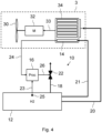
- the aircraft further comprises a non-propulsion system 29b (labeled S in the figure) normally powered with electricity by an on-board electrical source of the aircraft (not shown in the figure), called the main electrical source, independent of the fuel cell 14 of the hydrogen storage system and of the set of fuel cells 34.
- the aircraft also comprises an electrical circuit configured to electrically power the non-propulsion system 29b by the fuel cell 14 of the hydrogen storage system 10 in the event of a failure of the main electrical source, in particular when the aircraft is in flight.
- This electrical circuit comprises an electrical connection 24b between an electrical output of the fuel cell 14 and the non-propulsion system 29b, as well as a contactor 28b mounted in series on this electrical connection.
- the contactor 28b is controlled, for example by an electrical core (not shown) of the aircraft, so as to close the contactor in the event of a failure of the main electrical source.
- the aircraft further comprises an electrical system 29c (labeled R in the figure) separate from the processing unit 16, as well as an electrical circuit configured to electrically power this electrical system by the fuel cell of the hydrogen storage system when the aircraft is parked on the ground.
- This electrical circuit comprises an electrical connection 24c between an electrical output of the fuel cell 14 and the electrical system 29c, as well as a contactor 28c mounted in series on this electrical connection.
- the electrical system 29c is for example a system for heating the set of fuel cells 34 of the propulsion system 3, as illustrated by the arrow F in the figure.
- the contactor 28c is for example controlled by the processing unit 16, via a connection 25c, so as to control the closing of said contactor when the fuel cells of the set of fuel cells 34 must be heated while the aircraft is parked on the ground.
- the electrical system 29c is an electrical system external to the aircraft.
- the electrical connection 28c then comprises an electrical socket installed on board the aircraft (for example fixed to a wall of the fuselage 2 of the aircraft), as well as a removable electrical cable connected between this electrical socket and the electrical system 29c when the aircraft is parked on the ground.
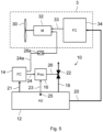
- the hydrogen storage system 10 is partially installed on board the aircraft 1. Indeed, the fuel cell 14 is then external to the aircraft, for example installed on board a service vehicle of an airport on which the aircraft is parked.
- An electrical socket Pe and a hydrogen pipe connector Ph are installed on board the aircraft, for example fixed to its fuselage 2.
- the electrical line 24 extends between the electrical socket Pe and the processing unit 16.
- the hydrogen pipe 21 extends between the hydrogen tank 12 and the hydrogen pipe connector Ph.
- a removable hydrogen pipe 21a connected to the fuel cell 14, is connected to the hydrogen pipe connector Ph and a removable electrical cable 24e, connected to an electrical output of the fuel cell 14, is connected to the electrical socket Pe.
- This particular embodiment has the advantage of not requiring the transport of the fuel cell 14 during the flight phases of the aircraft, which makes it possible to reduce the mass of the aircraft and therefore to reduce the energy consumption necessary for its propulsion.
Landscapes
- Engineering & Computer Science (AREA)
- Life Sciences & Earth Sciences (AREA)
- Sustainable Development (AREA)
- Sustainable Energy (AREA)
- Aviation & Aerospace Engineering (AREA)
- Power Engineering (AREA)
- Mechanical Engineering (AREA)
- Transportation (AREA)
- Chemical & Material Sciences (AREA)
- General Chemical & Material Sciences (AREA)
- Electrochemistry (AREA)
- Chemical Kinetics & Catalysis (AREA)
- Manufacturing & Machinery (AREA)
- Fuel Cell (AREA)
- Filling Or Discharging Of Gas Storage Vessels (AREA)
Claims (7)
- Anordnung, umfassend ein Flugzeug (1) und ein Wasserstoffspeichersystem (10), das einen Wasserstofftank (12) und ein Kontrollsystem zur Kontrolle des Verdampfens von Wasserstoff in dem Wasserstofftank, das Kontrollsystem umfassend:- eine Wasserstoffabführungsleitung (18), die zum einen mit dem Wasserstofftank und zum anderen mit einem steuerbaren Ventil (22) verbunden ist; und- eine Verarbeitungseinheit (16), die dazu ausgestaltet ist, das Ventil in Abhängigkeit von dem Druck in dem Tank zu steuern, so dass garantiert wird, dass der Wert des Drucks im Inneren des Wasserstofftanks einen vorbestimmten ersten Druckschwellenwert nicht überschreitet; das Wasserstoffspeichersystem (10) umfassend- eine Brennstoffzelle (14),wobei die Verarbeitungseinheit von der Brennstoffzelle elektrisch versorgt wird, dadurch gekennzeichnet, dass die Brennstoffzelle (14) dauerhaft mit dem Wasserstofftank verbunden ist, so dass ständig Strom erzeugt wird, solange Wasserstoff in dem Tank verbleibt, und dadurch, dass der Wasserstofftank (12) an Bord des Flugzeugs installiert ist und die Brennstoffzelle (14) des Wasserstoffspeichersystems in einer flugzeugexternen Einheit installiert ist, die dazu vorgesehen ist, mit dem Flugzeug durch eine lösbare Wasserstoffleitung (21a) und durch eine lösbare elektrische Verbindung (24e) verbunden zu werden.
- Anordnung nach Anspruch 1, dadurch gekennzeichnet, dass das Flugzeug ein Antriebssystem (3) umfasst, das durch aus dem Wasserstoffspeichersystem (10) hervorgegangenen Wasserstoff mit Energie versorgt wird.
- Anordnung nach Anspruch 2, dadurch gekennzeichnet, dass das Antriebssystem einen Motor umfasst, der durch Verbrennung von aus dem Wasserstoffspeichersystem hervorgegangenen Wasserstoff betrieben wird.
- Anordnung nach Anspruch 2, dadurch gekennzeichnet, dass das Antriebssystem einen Elektromotor (32) umfasst, der von einer Anordnung aus Brennstoffzellen (34), die von dem Wasserstoffspeichersystem (10) mit Wasserstoff versorgt werden, elektrisch versorgt wird.
- Anordnung nach Anspruch 4, dadurch gekennzeichnet, dass das Flugzeug ein elektrisches System (29c) umfasst, das verschieden von der Verarbeitungseinheit (16) ist, sowie einen elektrischen Schaltkreis (24c, 28c), der dazu ausgestaltet ist, dieses elektrische System durch die Brennstoffzelle (14) des Wasserstoffspeichersystems (10) elektrisch zu versorgen, wenn das Flugzeug am Boden abgestellt ist.
- Anordnung nach Anspruch 5, dadurch gekennzeichnet, dass dieses elektrische System (29c) einem System zum Erwärmen mindestens einer der Brennstoffzellen der Anordnung aus Brennstoffzellen (34) entspricht.
- Anordnung nach einem der Ansprüche 4 bis 6, dadurch gekennzeichnet, dass das Flugzeug einen elektrischen Schaltkreis umfasst, der dazu ausgestaltet ist, das Anschließen eines flugzeugexternen elektrischen Systems zu ermöglichen, wenn das Flugzeug am Boden abgestellt ist, und dieses System durch die Brennstoffzelle (14) des Wasserstoffspeichersystems (10) elektrisch zu versorgen.
Applications Claiming Priority (1)
| Application Number | Priority Date | Filing Date | Title |
|---|---|---|---|
| FR2102637A FR3120828A1 (fr) | 2021-03-17 | 2021-03-17 | Système de stockage d’hydrogène et aéronef comprenant un système de stockage d’hydrogène. |
Publications (2)
| Publication Number | Publication Date |
|---|---|
| EP4059760A1 EP4059760A1 (de) | 2022-09-21 |
| EP4059760B1 true EP4059760B1 (de) | 2025-06-25 |
Family
ID=76730655
Family Applications (1)
| Application Number | Title | Priority Date | Filing Date |
|---|---|---|---|
| EP22160689.0A Active EP4059760B1 (de) | 2021-03-17 | 2022-03-08 | Wasserstoffspeichersystem und luftfahrzeug mit einem wasserstoffspeichersystem |
Country Status (4)
| Country | Link |
|---|---|
| US (1) | US11769889B2 (de) |
| EP (1) | EP4059760B1 (de) |
| CN (1) | CN115158679A (de) |
| FR (1) | FR3120828A1 (de) |
Families Citing this family (7)
| Publication number | Priority date | Publication date | Assignee | Title |
|---|---|---|---|---|
| WO2022245427A2 (en) * | 2021-03-31 | 2022-11-24 | Zeroavia Ltd. | Refueling system for hydrogen fuel cell-powered aircraft |
| US11634232B1 (en) * | 2022-04-30 | 2023-04-25 | Beta Air, Llc | Hybrid propulsion systems for an electric aircraft |
| US12195192B2 (en) * | 2022-04-30 | 2025-01-14 | Beta Air Llc | Hybrid propulsion systems for an electric aircraft |
| US11639230B1 (en) * | 2022-04-30 | 2023-05-02 | Beta Air, Llc | System for an integral hybrid electric aircraft |
| US11933325B1 (en) * | 2023-08-11 | 2024-03-19 | ZeroAvia, Inc. | Thermal pumping of liquid hydrogen |
| EP4574677A1 (de) | 2023-12-21 | 2025-06-25 | Airbus Operations GmbH | Kraftstoffversorgungsanordnung, fahrzeug, externe energieumwandlungsvorrichtung und energiesystem damit |
| US20250223050A1 (en) * | 2024-01-10 | 2025-07-10 | Pratt & Whitney Canada Corp. | System for managing a hydrogen fuel tank aboard an aircraft |
Citations (3)
| Publication number | Priority date | Publication date | Assignee | Title |
|---|---|---|---|---|
| WO2017089679A1 (fr) * | 2015-11-27 | 2017-06-01 | Airbus Safran Launchers Sas | Systeme de generation d'energie destine a etre monte dans un aeronef. |
| EP3228546A1 (de) * | 2016-03-31 | 2017-10-11 | Bredenoord B.v. | Mobiles bodenstromaggregat und verfahren zur verwendung |
| US10654592B2 (en) * | 2016-02-12 | 2020-05-19 | The Boeing Company | Integration of fuel cell with cryogenic source for cooling and reactant |
Family Cites Families (12)
| Publication number | Priority date | Publication date | Assignee | Title |
|---|---|---|---|---|
| KR20120126996A (ko) * | 2011-05-13 | 2012-11-21 | 대우조선해양 주식회사 | 이산화탄소 운송선의 압력 탱크 모듈 및 이것을 제어하는 방법 |
| JP5959463B2 (ja) * | 2013-03-27 | 2016-08-02 | 本田技研工業株式会社 | 燃料電池車両及び移動体 |
| FR3016345B1 (fr) * | 2014-01-10 | 2017-09-01 | Snecma | Generateur electrique de secours avec pile a combustible a demarrage rapide |
| WO2016092495A2 (en) * | 2014-12-09 | 2016-06-16 | Zodiac Aerotechnics | Autonomous aircraft fuel cell system |
| CN108292762A (zh) * | 2015-06-29 | 2018-07-17 | 通用电气航空系统有限公司 | 用于飞机的燃料电池应急电源系统 |
| US10224556B2 (en) * | 2015-12-15 | 2019-03-05 | Hamilton Sundstrand Corporation | Integrated fuel cell aircraft pressurization and cooling system |
| GB2556061B (en) * | 2016-11-16 | 2019-07-24 | Ge Aviat Systems Ltd | Power source for an aircraft |
| JP7115279B2 (ja) * | 2018-12-11 | 2022-08-09 | トヨタ自動車株式会社 | 燃料電池システム |
| CN110131574B (zh) * | 2019-04-19 | 2021-05-11 | 中车长江车辆有限公司 | 基于组合阀的燃料电池供氢系统及其充氢供氢方法 |
| FR3097202B1 (fr) * | 2019-06-14 | 2024-02-23 | Airbus | Systeme autonome de propulsion a helice pour un aeronef, ledit systeme autonome de propulsion a helice comportant une pile a combustible |
| US20210207540A1 (en) * | 2020-01-02 | 2021-07-08 | United Technologies Corporation | Systems and methods for fuel cell auxiliary power in secondary fuel applications |
| US11525402B2 (en) * | 2020-01-07 | 2022-12-13 | Raytheon Technologies Corporation | Combustion chamber with solid fuel |
-
2021
- 2021-03-17 FR FR2102637A patent/FR3120828A1/fr not_active Ceased
-
2022
- 2022-03-01 CN CN202210192247.2A patent/CN115158679A/zh active Pending
- 2022-03-08 EP EP22160689.0A patent/EP4059760B1/de active Active
- 2022-03-10 US US17/691,395 patent/US11769889B2/en active Active
Patent Citations (3)
| Publication number | Priority date | Publication date | Assignee | Title |
|---|---|---|---|---|
| WO2017089679A1 (fr) * | 2015-11-27 | 2017-06-01 | Airbus Safran Launchers Sas | Systeme de generation d'energie destine a etre monte dans un aeronef. |
| US10654592B2 (en) * | 2016-02-12 | 2020-05-19 | The Boeing Company | Integration of fuel cell with cryogenic source for cooling and reactant |
| EP3228546A1 (de) * | 2016-03-31 | 2017-10-11 | Bredenoord B.v. | Mobiles bodenstromaggregat und verfahren zur verwendung |
Also Published As
| Publication number | Publication date |
|---|---|
| US11769889B2 (en) | 2023-09-26 |
| EP4059760A1 (de) | 2022-09-21 |
| FR3120828A1 (fr) | 2022-09-23 |
| US20220302477A1 (en) | 2022-09-22 |
| CN115158679A (zh) | 2022-10-11 |
Similar Documents
| Publication | Publication Date | Title |
|---|---|---|
| EP4059760B1 (de) | Wasserstoffspeichersystem und luftfahrzeug mit einem wasserstoffspeichersystem | |
| EP2984385B1 (de) | Verfahren und system zur behandlung und zufuhr von erdgas in einer vorrichtung zur energieerzeugung zum bewegen eines schiffes | |
| WO2008139096A2 (fr) | Turbomoteur de helicoptere comrpenant un generateur de gaz et une turbine libre | |
| CA3200443A1 (fr) | Dispositif de production d'energie comportant une unite de production de dihydrogene; procede utilisant ce dispositif | |
| EP2017916A2 (de) | Abschalten einer mit reinem Sauerstoff gespeisten Brennstoffzelle | |
| FR3098649A1 (fr) | Systeme de production electrique pour un aeronef comportant une pile a combustible | |
| EP3060787B1 (de) | Autogene druckbeaufschlagungsvorrichtung für einen treibmittelbehälter | |
| CA3066843A1 (fr) | Systeme d'inertage d'au moins un volume dans un aeronef via au moins une pile a combustible | |
| FR3113649A1 (fr) | Système d’inertage et aéronef et méthode d’inertage associés | |
| WO2015079155A1 (fr) | Procede et systeme pour la production optimisee d'energie non propulsive | |
| FR2816762A1 (fr) | Procede et dispositif de securite pour le demarrage et l'arret d'une pile a combustible | |
| FR3009544A1 (fr) | Systemes electriques de la nacelle energetiquement autonomes | |
| EP1455405A2 (de) | Brennstoffzellen enthaltendes Fahrzeugantriebssystem | |
| FR2999342A1 (fr) | Systeme de production d'electricite embarque avec pile a combustible | |
| EP4195335A1 (de) | Wärmemanagementsystem für ein brennstoffzellen-sekundärbatterie-hybridsystem | |
| FR2941095A1 (fr) | Procede de rechauffage de batteries pour un vehicule dote d'au moins deux stockeurs d'energie electrique | |
| FR2861220A1 (fr) | Dispositif et procede de prechauffage d'un systeme pile a combustible | |
| FR2813994A1 (fr) | Pile a combustible et procede de protection d'une telle pile contre le gel | |
| FR2860105A1 (fr) | Systeme et procede de mise en oeuvre d'une pile a combustible d'un vehicule | |
| FR2865855A1 (fr) | Dispositif de demarrage d'une pile a combustible | |
| WO2025242622A1 (fr) | Systeme de gestion de la securite d'une batterie et procede associe | |
| FR2881579A1 (fr) | Systeme de pile a combustible pour vehicule automobile a moteur de traction electrique et procede de production d'eau pour un tel systeme | |
| FR2896917A1 (fr) | Vehicule automobile comprenant une pile a combustible et utilisation d'une telle pile | |
| FR3160064A3 (fr) | Module à pile à combustible et modules d’organes auxiliaires avec logique de contrôle embarquée, adaptés aux usages aéronautiques | |
| FR2867901A1 (fr) | Dispositif de maintien en temperature d'un reformeur, vehicule l'incorporant, et procede de commande |
Legal Events
| Date | Code | Title | Description |
|---|---|---|---|
| PUAI | Public reference made under article 153(3) epc to a published international application that has entered the european phase |
Free format text: ORIGINAL CODE: 0009012 |
|
| STAA | Information on the status of an ep patent application or granted ep patent |
Free format text: STATUS: EXAMINATION IS IN PROGRESS |
|
| 17P | Request for examination filed |
Effective date: 20220309 |
|
| AK | Designated contracting states |
Kind code of ref document: A1 Designated state(s): AL AT BE BG CH CY CZ DE DK EE ES FI FR GB GR HR HU IE IS IT LI LT LU LV MC MK MT NL NO PL PT RO RS SE SI SK SM TR |
|
| RBV | Designated contracting states (corrected) |
Designated state(s): AL AT BE BG CH CY CZ DE DK EE ES FI FR GB GR HR HU IE IS IT LI LT LU LV MC MK MT NL NO PL PT RO RS SE SI SK SM TR |
|
| GRAP | Despatch of communication of intention to grant a patent |
Free format text: ORIGINAL CODE: EPIDOSNIGR1 |
|
| STAA | Information on the status of an ep patent application or granted ep patent |
Free format text: STATUS: GRANT OF PATENT IS INTENDED |
|
| RIC1 | Information provided on ipc code assigned before grant |
Ipc: B64D 37/30 20060101ALI20250306BHEP Ipc: B64D 37/32 20060101ALI20250306BHEP Ipc: H01M 8/249 20160101ALI20250306BHEP Ipc: H01M 8/04746 20160101ALI20250306BHEP Ipc: H01M 8/0444 20160101ALI20250306BHEP Ipc: H01M 8/0438 20160101ALI20250306BHEP Ipc: H01M 8/0432 20160101ALI20250306BHEP Ipc: H01M 8/04082 20160101ALI20250306BHEP Ipc: F01C 7/00 20060101ALI20250306BHEP Ipc: B64D 41/00 20060101ALI20250306BHEP Ipc: B64D 27/24 20060101ALI20250306BHEP Ipc: B60L 58/34 20190101ALI20250306BHEP Ipc: B60L 50/70 20190101ALI20250306BHEP Ipc: B60L 1/02 20060101ALI20250306BHEP Ipc: B64D 27/355 20240101ALI20250306BHEP Ipc: B64D 27/34 20240101ALI20250306BHEP Ipc: B60L 1/00 20060101ALI20250306BHEP Ipc: B60L 3/00 20190101AFI20250306BHEP |
|
| INTG | Intention to grant announced |
Effective date: 20250409 |
|
| GRAS | Grant fee paid |
Free format text: ORIGINAL CODE: EPIDOSNIGR3 |
|
| GRAA | (expected) grant |
Free format text: ORIGINAL CODE: 0009210 |
|
| STAA | Information on the status of an ep patent application or granted ep patent |
Free format text: STATUS: THE PATENT HAS BEEN GRANTED |
|
| AK | Designated contracting states |
Kind code of ref document: B1 Designated state(s): AL AT BE BG CH CY CZ DE DK EE ES FI FR GB GR HR HU IE IS IT LI LT LU LV MC MK MT NL NO PL PT RO RS SE SI SK SM TR |
|
| REG | Reference to a national code |
Ref country code: GB Ref legal event code: FG4D Free format text: NOT ENGLISH |
|
| REG | Reference to a national code |
Ref country code: CH Ref legal event code: EP |
|
| REG | Reference to a national code |
Ref country code: DE Ref legal event code: R096 Ref document number: 602022016282 Country of ref document: DE |
|
| REG | Reference to a national code |
Ref country code: CH Ref legal event code: EP |
|
| REG | Reference to a national code |
Ref country code: IE Ref legal event code: FG4D Free format text: LANGUAGE OF EP DOCUMENT: FRENCH |
|
| PG25 | Lapsed in a contracting state [announced via postgrant information from national office to epo] |
Ref country code: FI Free format text: LAPSE BECAUSE OF FAILURE TO SUBMIT A TRANSLATION OF THE DESCRIPTION OR TO PAY THE FEE WITHIN THE PRESCRIBED TIME-LIMIT Effective date: 20250625 |
|
| REG | Reference to a national code |
Ref country code: LT Ref legal event code: MG9D |
|
| PG25 | Lapsed in a contracting state [announced via postgrant information from national office to epo] |
Ref country code: NO Free format text: LAPSE BECAUSE OF FAILURE TO SUBMIT A TRANSLATION OF THE DESCRIPTION OR TO PAY THE FEE WITHIN THE PRESCRIBED TIME-LIMIT Effective date: 20250925 Ref country code: GR Free format text: LAPSE BECAUSE OF FAILURE TO SUBMIT A TRANSLATION OF THE DESCRIPTION OR TO PAY THE FEE WITHIN THE PRESCRIBED TIME-LIMIT Effective date: 20250926 |
|
| PG25 | Lapsed in a contracting state [announced via postgrant information from national office to epo] |
Ref country code: BG Free format text: LAPSE BECAUSE OF FAILURE TO SUBMIT A TRANSLATION OF THE DESCRIPTION OR TO PAY THE FEE WITHIN THE PRESCRIBED TIME-LIMIT Effective date: 20250625 |
|
| PG25 | Lapsed in a contracting state [announced via postgrant information from national office to epo] |
Ref country code: HR Free format text: LAPSE BECAUSE OF FAILURE TO SUBMIT A TRANSLATION OF THE DESCRIPTION OR TO PAY THE FEE WITHIN THE PRESCRIBED TIME-LIMIT Effective date: 20250625 |
|
| PG25 | Lapsed in a contracting state [announced via postgrant information from national office to epo] |
Ref country code: RS Free format text: LAPSE BECAUSE OF FAILURE TO SUBMIT A TRANSLATION OF THE DESCRIPTION OR TO PAY THE FEE WITHIN THE PRESCRIBED TIME-LIMIT Effective date: 20250925 |
|
| PG25 | Lapsed in a contracting state [announced via postgrant information from national office to epo] |
Ref country code: LV Free format text: LAPSE BECAUSE OF FAILURE TO SUBMIT A TRANSLATION OF THE DESCRIPTION OR TO PAY THE FEE WITHIN THE PRESCRIBED TIME-LIMIT Effective date: 20250625 |
|
| REG | Reference to a national code |
Ref country code: NL Ref legal event code: MP Effective date: 20250625 |
|
| PG25 | Lapsed in a contracting state [announced via postgrant information from national office to epo] |
Ref country code: NL Free format text: LAPSE BECAUSE OF FAILURE TO SUBMIT A TRANSLATION OF THE DESCRIPTION OR TO PAY THE FEE WITHIN THE PRESCRIBED TIME-LIMIT Effective date: 20250625 |
|
| PG25 | Lapsed in a contracting state [announced via postgrant information from national office to epo] |
Ref country code: PT Free format text: LAPSE BECAUSE OF FAILURE TO SUBMIT A TRANSLATION OF THE DESCRIPTION OR TO PAY THE FEE WITHIN THE PRESCRIBED TIME-LIMIT Effective date: 20251027 |
|
| REG | Reference to a national code |
Ref country code: AT Ref legal event code: MK05 Ref document number: 1806151 Country of ref document: AT Kind code of ref document: T Effective date: 20250625 |
|
| PG25 | Lapsed in a contracting state [announced via postgrant information from national office to epo] |
Ref country code: IS Free format text: LAPSE BECAUSE OF FAILURE TO SUBMIT A TRANSLATION OF THE DESCRIPTION OR TO PAY THE FEE WITHIN THE PRESCRIBED TIME-LIMIT Effective date: 20251025 |
|
| PG25 | Lapsed in a contracting state [announced via postgrant information from national office to epo] |
Ref country code: AT Free format text: LAPSE BECAUSE OF FAILURE TO SUBMIT A TRANSLATION OF THE DESCRIPTION OR TO PAY THE FEE WITHIN THE PRESCRIBED TIME-LIMIT Effective date: 20250625 Ref country code: SM Free format text: LAPSE BECAUSE OF FAILURE TO SUBMIT A TRANSLATION OF THE DESCRIPTION OR TO PAY THE FEE WITHIN THE PRESCRIBED TIME-LIMIT Effective date: 20250625 |
|
| PG25 | Lapsed in a contracting state [announced via postgrant information from national office to epo] |
Ref country code: CZ Free format text: LAPSE BECAUSE OF FAILURE TO SUBMIT A TRANSLATION OF THE DESCRIPTION OR TO PAY THE FEE WITHIN THE PRESCRIBED TIME-LIMIT Effective date: 20250625 |
|
| PG25 | Lapsed in a contracting state [announced via postgrant information from national office to epo] |
Ref country code: PL Free format text: LAPSE BECAUSE OF FAILURE TO SUBMIT A TRANSLATION OF THE DESCRIPTION OR TO PAY THE FEE WITHIN THE PRESCRIBED TIME-LIMIT Effective date: 20250625 |
|
| PG25 | Lapsed in a contracting state [announced via postgrant information from national office to epo] |
Ref country code: EE Free format text: LAPSE BECAUSE OF FAILURE TO SUBMIT A TRANSLATION OF THE DESCRIPTION OR TO PAY THE FEE WITHIN THE PRESCRIBED TIME-LIMIT Effective date: 20250625 |
|
| PG25 | Lapsed in a contracting state [announced via postgrant information from national office to epo] |
Ref country code: SK Free format text: LAPSE BECAUSE OF FAILURE TO SUBMIT A TRANSLATION OF THE DESCRIPTION OR TO PAY THE FEE WITHIN THE PRESCRIBED TIME-LIMIT Effective date: 20250625 |
|
| PG25 | Lapsed in a contracting state [announced via postgrant information from national office to epo] |
Ref country code: ES Free format text: LAPSE BECAUSE OF FAILURE TO SUBMIT A TRANSLATION OF THE DESCRIPTION OR TO PAY THE FEE WITHIN THE PRESCRIBED TIME-LIMIT Effective date: 20250625 |
|
| PGFP | Annual fee paid to national office [announced via postgrant information from national office to epo] |
Ref country code: GB Payment date: 20260324 Year of fee payment: 5 |
|
| PG25 | Lapsed in a contracting state [announced via postgrant information from national office to epo] |
Ref country code: DK Free format text: LAPSE BECAUSE OF FAILURE TO SUBMIT A TRANSLATION OF THE DESCRIPTION OR TO PAY THE FEE WITHIN THE PRESCRIBED TIME-LIMIT Effective date: 20250625 |
|
| PGFP | Annual fee paid to national office [announced via postgrant information from national office to epo] |
Ref country code: DE Payment date: 20260319 Year of fee payment: 5 |
|
| PG25 | Lapsed in a contracting state [announced via postgrant information from national office to epo] |
Ref country code: IT Free format text: LAPSE BECAUSE OF FAILURE TO SUBMIT A TRANSLATION OF THE DESCRIPTION OR TO PAY THE FEE WITHIN THE PRESCRIBED TIME-LIMIT Effective date: 20250625 |
|
| PGFP | Annual fee paid to national office [announced via postgrant information from national office to epo] |
Ref country code: FR Payment date: 20260323 Year of fee payment: 5 |
|
| PLBE | No opposition filed within time limit |
Free format text: ORIGINAL CODE: 0009261 |
|
| STAA | Information on the status of an ep patent application or granted ep patent |
Free format text: STATUS: NO OPPOSITION FILED WITHIN TIME LIMIT |