EP2881981A1 - Appareil et procédé de serrage électrostatique - Google Patents
Appareil et procédé de serrage électrostatique Download PDFInfo
- Publication number
- EP2881981A1 EP2881981A1 EP14193534.6A EP14193534A EP2881981A1 EP 2881981 A1 EP2881981 A1 EP 2881981A1 EP 14193534 A EP14193534 A EP 14193534A EP 2881981 A1 EP2881981 A1 EP 2881981A1
- Authority
- EP
- European Patent Office
- Prior art keywords
- wafer
- time
- clamping
- voltage
- plasma
- Prior art date
- Legal status (The legal status is an assumption and is not a legal conclusion. Google has not performed a legal analysis and makes no representation as to the accuracy of the status listed.)
- Granted
Links
- 238000000034 method Methods 0.000 title claims abstract description 55
- 238000012545 processing Methods 0.000 claims abstract description 23
- 239000000758 substrate Substances 0.000 claims abstract description 15
- 239000007789 gas Substances 0.000 claims description 32
- 239000001307 helium Substances 0.000 claims description 17
- 229910052734 helium Inorganic materials 0.000 claims description 17
- SWQJXJOGLNCZEY-UHFFFAOYSA-N helium atom Chemical compound [He] SWQJXJOGLNCZEY-UHFFFAOYSA-N 0.000 claims description 17
- 238000012360 testing method Methods 0.000 claims description 9
- 230000001965 increasing effect Effects 0.000 claims description 6
- 239000000463 material Substances 0.000 claims description 3
- 229910052594 sapphire Inorganic materials 0.000 claims description 3
- 239000010980 sapphire Substances 0.000 claims description 3
- 238000012544 monitoring process Methods 0.000 claims description 2
- 239000010453 quartz Substances 0.000 claims description 2
- VYPSYNLAJGMNEJ-UHFFFAOYSA-N silicon dioxide Inorganic materials O=[Si]=O VYPSYNLAJGMNEJ-UHFFFAOYSA-N 0.000 claims description 2
- 238000002474 experimental method Methods 0.000 claims 1
- 239000011521 glass Substances 0.000 claims 1
- HBMJWWWQQXIZIP-UHFFFAOYSA-N silicon carbide Chemical compound [Si+]#[C-] HBMJWWWQQXIZIP-UHFFFAOYSA-N 0.000 claims 1
- 229910010271 silicon carbide Inorganic materials 0.000 claims 1
- 235000012431 wafers Nutrition 0.000 description 121
- 230000008569 process Effects 0.000 description 20
- 238000013508 migration Methods 0.000 description 13
- 230000005012 migration Effects 0.000 description 13
- 238000012546 transfer Methods 0.000 description 12
- 230000035515 penetration Effects 0.000 description 6
- 238000001816 cooling Methods 0.000 description 4
- 238000005530 etching Methods 0.000 description 4
- 230000010363 phase shift Effects 0.000 description 4
- 238000001020 plasma etching Methods 0.000 description 4
- 230000007704 transition Effects 0.000 description 4
- 230000008901 benefit Effects 0.000 description 3
- 238000005137 deposition process Methods 0.000 description 3
- 230000000149 penetrating effect Effects 0.000 description 3
- 230000008859 change Effects 0.000 description 2
- 239000004020 conductor Substances 0.000 description 2
- 230000007423 decrease Effects 0.000 description 2
- 238000013461 design Methods 0.000 description 2
- 230000000694 effects Effects 0.000 description 2
- 230000005684 electric field Effects 0.000 description 2
- 230000004907 flux Effects 0.000 description 2
- 239000011810 insulating material Substances 0.000 description 2
- 239000002245 particle Substances 0.000 description 2
- 238000002310 reflectometry Methods 0.000 description 2
- 239000004065 semiconductor Substances 0.000 description 2
- 230000006641 stabilisation Effects 0.000 description 2
- XLYOFNOQVPJJNP-UHFFFAOYSA-N water Substances O XLYOFNOQVPJJNP-UHFFFAOYSA-N 0.000 description 2
- 239000004642 Polyimide Substances 0.000 description 1
- 230000004308 accommodation Effects 0.000 description 1
- 238000009825 accumulation Methods 0.000 description 1
- 230000009471 action Effects 0.000 description 1
- PNEYBMLMFCGWSK-UHFFFAOYSA-N aluminium oxide Inorganic materials [O-2].[O-2].[O-2].[Al+3].[Al+3] PNEYBMLMFCGWSK-UHFFFAOYSA-N 0.000 description 1
- 238000013459 approach Methods 0.000 description 1
- 238000001636 atomic emission spectroscopy Methods 0.000 description 1
- 230000015572 biosynthetic process Effects 0.000 description 1
- 230000015556 catabolic process Effects 0.000 description 1
- 238000006243 chemical reaction Methods 0.000 description 1
- 238000007796 conventional method Methods 0.000 description 1
- 239000012809 cooling fluid Substances 0.000 description 1
- 238000000151 deposition Methods 0.000 description 1
- 230000008021 deposition Effects 0.000 description 1
- 238000010586 diagram Methods 0.000 description 1
- 239000003989 dielectric material Substances 0.000 description 1
- 230000003292 diminished effect Effects 0.000 description 1
- 238000009826 distribution Methods 0.000 description 1
- 230000002708 enhancing effect Effects 0.000 description 1
- 238000010438 heat treatment Methods 0.000 description 1
- 230000006698 induction Effects 0.000 description 1
- 230000001939 inductive effect Effects 0.000 description 1
- 239000011261 inert gas Substances 0.000 description 1
- 238000009413 insulation Methods 0.000 description 1
- 239000012212 insulator Substances 0.000 description 1
- 238000005305 interferometry Methods 0.000 description 1
- 238000011835 investigation Methods 0.000 description 1
- 238000010849 ion bombardment Methods 0.000 description 1
- 150000002500 ions Chemical class 0.000 description 1
- 238000004519 manufacturing process Methods 0.000 description 1
- 230000007246 mechanism Effects 0.000 description 1
- 230000003287 optical effect Effects 0.000 description 1
- 229920001721 polyimide Polymers 0.000 description 1
- 230000005855 radiation Effects 0.000 description 1
- 238000012216 screening Methods 0.000 description 1
- 238000000926 separation method Methods 0.000 description 1
Images


Classifications
-
- H—ELECTRICITY
- H01—ELECTRIC ELEMENTS
- H01L—SEMICONDUCTOR DEVICES NOT COVERED BY CLASS H10
- H01L21/00—Processes or apparatus adapted for the manufacture or treatment of semiconductor or solid state devices or of parts thereof
- H01L21/67—Apparatus specially adapted for handling semiconductor or electric solid state devices during manufacture or treatment thereof; Apparatus specially adapted for handling wafers during manufacture or treatment of semiconductor or electric solid state devices or components ; Apparatus not specifically provided for elsewhere
- H01L21/683—Apparatus specially adapted for handling semiconductor or electric solid state devices during manufacture or treatment thereof; Apparatus specially adapted for handling wafers during manufacture or treatment of semiconductor or electric solid state devices or components ; Apparatus not specifically provided for elsewhere for supporting or gripping
- H01L21/6831—Apparatus specially adapted for handling semiconductor or electric solid state devices during manufacture or treatment thereof; Apparatus specially adapted for handling wafers during manufacture or treatment of semiconductor or electric solid state devices or components ; Apparatus not specifically provided for elsewhere for supporting or gripping using electrostatic chucks
- H01L21/6833—Details of electrostatic chucks
-
- B—PERFORMING OPERATIONS; TRANSPORTING
- B23—MACHINE TOOLS; METAL-WORKING NOT OTHERWISE PROVIDED FOR
- B23Q—DETAILS, COMPONENTS, OR ACCESSORIES FOR MACHINE TOOLS, e.g. ARRANGEMENTS FOR COPYING OR CONTROLLING; MACHINE TOOLS IN GENERAL CHARACTERISED BY THE CONSTRUCTION OF PARTICULAR DETAILS OR COMPONENTS; COMBINATIONS OR ASSOCIATIONS OF METAL-WORKING MACHINES, NOT DIRECTED TO A PARTICULAR RESULT
- B23Q3/00—Devices holding, supporting, or positioning work or tools, of a kind normally removable from the machine
- B23Q3/15—Devices for holding work using magnetic or electric force acting directly on the work
-
- H—ELECTRICITY
- H02—GENERATION; CONVERSION OR DISTRIBUTION OF ELECTRIC POWER
- H02N—ELECTRIC MACHINES NOT OTHERWISE PROVIDED FOR
- H02N13/00—Clutches or holding devices using electrostatic attraction, e.g. using Johnson-Rahbek effect
Definitions
- the invention relates to method and apparatus for electrostatically clamping a dielectric wafer (a work piece) to a process table, typically for use in plasma processing apparatus.
- Plasma etching and deposition processes rely on maintaining the wafer temperature within a permitted range. Wafer temperature control is achieved by clamping the wafer to a support table, of which temperature is maintained by using cooling fluid. Deposition processes typically use a wafer temperature in the range 50 - 500C; etching processes typically use -100C to +250C. It is desirable to keep the wafer within a few degrees of a target temperature, following temperature stabilisation. During processing, energy is applied to the front surface of the wafer by the plasma process in the form of ion bombardment and/or chemical reaction, especially in etch processing.
- Heat can be flowing either from the table to the wafer or from the wafer to the table during processing, with wafer cooling being more common in etch, and wafer heating the norm in deposition processes. Improving the thermal contact between the wafer and the table decreases the temperature stabilisation time and increases the maximum heat flux to the table, for a given maximum wafer temperature. Both of these effects help to increase the throughput of wafers. Better thermal contact also decreases the variation in wafer temperature caused by other process variances, tending to improve process repeatability.
- H W m -2 is the heat flux between the wafer and table T wafer K is the wafer temperature T table K is the table temperature h W m -2 K -1 is a linear conduction heat transfer coefficient e 12 is the effective emissivity of the pair of surfaces for radiative heat transfer s sb W m -2 K -4 is the Stefan-Boltzmann constant
- the heat transfer coefficient depends on the gap between the surfaces, the pressure and nature of the gas between the surfaces, and the accommodation coefficient, which describes the degree to which gas particles coming into contact with each surface come to thermal equilibrium with that surface.
- Increasing the heat transfer coefficient is achieved by raising the pressure between the wafer and the table, normally accompanied by clamping the wafer to the table.
- the use of helium gas pressure normally in the range 100 - 3000 Pa behind a wafer for heat transfer in semiconductor processing is known as 'helium backside cooling'.
- Electrostatic clamping of semiconducting wafers has become the more conventional technique especially in plasma etching. The technique has been disclosed in many places, for example US 5,103,367 ; G A Wardly Rev Sci Instruments 44 (10) pp 1506-1509 (1973 ); US 6,297,274 .
- the electrostatic clamp or 'chuck' is often abbreviated as ESC.
- Another method is to use multiple zones with independent voltage controls, so that some zones retain the wafer while one zone is switched. This has the disadvantage of requiring multiple power supplies and voltage feed-throughs.
- Clamping of insulating materials is more difficult than conductors or semiconductors. It relies on inducing polarisation of the dielectric material of the wafer, using closely spaced or 'interdigitated' conducting electrodes embedded in an insulating medium ( US5838529 ).
- the voltage required to clamp the wafer is typically substantially higher than for non-insulating wafers, otherwise the clamp force is more limited.
- the electrostatic clamp conductors are usually covered with an insulating layer, which can be vulnerable to electrical breakdown. Together these restrict the maximum pressure that can be used beneath the wafer to promote heat transfer.
- a method of electrostatically clamping a dielectric wafer to a processing table during plasma processing comprising applying respective switching voltages of opposite first and second polarities to adjacent electrodes wherein polarisation charges are induced in the wafer with opposite polarity to the respective underlying electrodes thereby electrostatically clamping the wafer to the table; and, after a predetermined time (t on ), reversing the polarities of the voltages so that the polarisation charges and electrostatic clamping continues characterized in that:
- plasma processing apparatus for including a plasma generating chamber within which is provided a processing table having embedded interdigitated electrodes and on which a dielectric wafer is located in use; a voltage source coupled with the interdigitated electrodes; and a control system programmed to control the voltage source to apply respective switching voltages of opposite first and second polarities to adjacent electrodes wherein polarisation charges are induced in the wafer with opposite polarity to the respective underlying electrodes thereby electrostatically clamping the wafer to the table; and after a predetermined time (t on ) reversing the polarities of the voltages to the second polarity so that the polarisation charges and electrostatic clamping continues. characterized in that:
- a method of generating and storing instructions on a record medium for use by a control system of plasma processing apparatus comprising applying respective switching voltages of opposite first and second polarities to adjacent electrodes wherein polarisation charges are induced in the wafer with opposite polarity to the respective underlying electrodes thereby electrostatically clamping the wafer to the substrate; and after a predetermined time (t on ) reversing the polarities of the voltages so that the polarisation charges and electrostatic clamping continues characterized in that:
- the gas used to provide the background pressure is typically an inert gas such as Helium.
- the necessary minimum period between voltage switching events depends on several time constants, each of which are measured before putting the ESC into service with a specific plasma process. These are:
- loss of clamping by the first and second predetermined amounts is determined by a corresponding increase in the flow of backside gas to maintain the same pressure. This can be gradual, indicating slow loss of clamping, and in this case we define loss of clamping to be a certain percentage increase, e.g. 20-25% increase, in the gas flow. It can also be very sudden, indicating complete loss of clamping (a 'pop off' event).
- T1 can be a few seconds
- T2 can be in the range 5 seconds to 10 minutes
- T3 can be greater than one hour.
- the period (t on ) between voltage reversal events during clamping in use with a plasma is less than the time to lose clamping from plasma charge migration (T2), or from charge migration within the ESC dielectric (T3) and greater than the time to establish wafer polarisation charge (T1).
- the time for the transition from one polarity to the other can be longer than the wafer impact time or wafer escape time as disclosed in the method of Kellerman et al (US 6,947,274 ).
- the switching time period is also substantially longer than disclosed in the alternating voltage methods of Kellerman et al or Horwitz and Boronkay (US 5,103,167 ), so that in our method most of the time has a constant clamping voltage.
- the voltage reversal time t s should be shorter than either T1 or T2 and is preferably much shorter than the shorter of these.
- the voltages may be switched in a regular manner but this is not essential and indeed the two polarities do not need to be applied for equal times although this is preferred in practice.
- the wafer surface may acquire a DC offset voltage due to the rectifying nature of the plasma. Where means exist for this to be measured or estimated, for example using a conducting test wafer, then the ESC voltages can be offset from ground by a similar amount.
- the mechanical clamp allows an increased backside gas pressure for increased heat transfer, in the range 1000-2000Pa, while the electrostatic clamp force tends to flatten the wafer against the table. This makes the gap under the wafer more uniform, and makes the heat transfer more uniform across the area of the wafer.
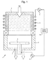
- Figure 1 illustrates the primary components of a plasma processing chamber 1 including an airtight housing 2 within which is mounted a process table 3. Gas is supplied through an upper wall 4 of the housing 2 and is converted to plasma via an induction coil 5 coupled to a power source 6 and encircling an upper part of the housing 2.
- Plasma gas is extracted under pump action via an opening 7 in a lower wall of the housing 2.
- the table 3 is coupled with a source 8 of RF power, typically at 13.56 MHz and is provided with ESC clamping voltages and a gas feed for wafer backside heat transfer (not shown in Figure 1 but described later).
- the power sources 6,8 are connected to a control system 10.
- a wafer (not shown) is placed on the table 3.
- Process gases flow through the plasma source where they are ionised and dissociated, and pass via contact with a wafer on the table 3 to the exit port 7.
- the table is normally driven with RF power, often at 13.56MHz, and provided with ESC clamping voltages and a gas feed for wafer backside heat transfer.
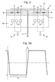
- FIG. 2 illustrates the ESC table 3 in more detail.
- This comprises a conventional RF driven table 20 with embedded cooling channels 22 and an upper dielectric, insulating layer 24.
- This layer is made typically from alumina, quartz, polyimide or similar materials.
- Two interdigitated sets of electrodes 26,28 are embedded in the layer 24. (Only some of the electrodes 26,28 are shown and labelled.)
- a dielectric wafer 30 is shown on the insulating layer 24 having been placed on that layer using retractable lifting pins (not shown).
- the electrodes 26,28 are isolated from the wafer 30 by the insulating material of the layer 24 which also insulates the electrodes from the underlying base 20.
- the ESC electrodes 26,28 are connected to one or more power supplies 34,32 via electrical feed-throughs (shown by dashed lines), the power supplies being controlled in turn by the control system 10 ( Figure 1 ).
- Helium gas to maintain a wafer backside pressure is supplied into the region between the wafer 30 and layer 24 via a supply pipe 23 extending through the table 20 and layer 24.
- a voltage is applied to one set of interconnected electrodes, e.g., 26, and the polarity of that voltage is reversed periodically (between +V and -V) as shown in Figure 3A .
- another voltage is applied to the other set of interconnected electrodes, e.g. 28.
- the voltage applied to each electrode 28 usually has the same magnitude but in opposite polarity with respect to each electrode 26.
- the time during which a steady state voltage is applied is labelled t on and the time during which the voltage is switched from one polarity to the other is labelled t s .
- FIG. 3B and 3C A specific example of a pair of opposed voltage waveforms applied to respective sets of electrodes 26,28 are shown in Figures 3B and 3C . As can be seen, the voltage is varied exactly in phase but in opposite senses between +3000V and - 3000V. The compensation for DC bias during the plasma on period is also depicted.
- both the polarisation charge and the penetration edge charge retain their positions at least partially during switching.
- the edge region remains inactive for clamping, while the clamp force in the central region is substantially maintained by the wafer polarisation delaying the change of charge state of the embedded electrodes.
- t s and t on are set following a determination of T 1 , T 2 , and T 3 defined above.
- FIG. 9 This is exemplified in Figure 9 which relates to Ar plasma (50 sccm Ar, 3 mTorr, 2000 W ICP, 100 W RIE). Helium pressure 10 Torr. Flow increased in this case by 25% in 200 seconds.
- T3 a steady clamping voltage was applied for an hour with a helium backside pressure of 10 Torr, in the absence of plasma. No significant change was observed in the helium flow rate, indicating that in this case T3 is greater than one hour, and that charge migration within the ESC did not limit the switching time in this case.
- the time (t on ) between voltage switching should be less than T 2 which is less than 200 seconds (partial loss of clamping) and preferably less than 40 seconds (20% of this time), but greater than 5 seconds (T 1 time to establish polarisation charge).
- the edge charge migration time constant is shorter than the time constant (>1 hour) for loss of clamping by lateral charge migration in the bulk of the insulator in this case.
- the time (t s ) to switch between one polarity and another should be less than 2 seconds (loss of wafer polarisation charge) and preferably less than 0.4 seconds (20% of this time).
- the edge charge migration has a longer time constant in this case, and does not limit the period for voltage reversal.
- an edge ring 40 extends around the insulating layer 24 and a groove 41 in the table 20 and has an upper surface 42 flush with the upper surface 43 of the insulating layer 24.
- the edge ring 40 is fitted about the insulating layer 24 while the wafer 30 extends over a part of the edge ring 40.
- an edge ring 42 is provided which has an upper ring section 46 which protrudes above the level of the wafer 30 preferably by an amount in the range 0.5-3mm.
- This form of edge ring can extend the time T2 up to four times compared to the version shown in Figure 15 .
- the edge ring reduces the ingress of charges at the wafer edge.
- the extension in time must be balanced in practice with the uniformity of etching to the wafer edge, because excessive edge ring height suppresses the etch rate at the wafer edge.
- the edge ring may be conductive or a dielectric.
- Figure 11 is a graph showing the problem using existing prior art with 10 Torr He back pressure.
- He flow rate starts to increase. This time is defined as He leak time in Figure 11 .
- the wafer will eventually pop off later on at around 250 secs.
- Figure 12 is a graph showing He flow and pressure for a 30 minutes processing of a sapphire wafer with 10 Torr back side pressure.
- Figure 14 is a data plot showing sapphire wafer temperature as a function of process time. It can be seen that the temperature difference between the wafer and the ESC is kept substantially constant after reaching steady state.
Landscapes
- Engineering & Computer Science (AREA)
- Physics & Mathematics (AREA)
- Condensed Matter Physics & Semiconductors (AREA)
- General Physics & Mathematics (AREA)
- Manufacturing & Machinery (AREA)
- Computer Hardware Design (AREA)
- Microelectronics & Electronic Packaging (AREA)
- Power Engineering (AREA)
- Mechanical Engineering (AREA)
- Container, Conveyance, Adherence, Positioning, Of Wafer (AREA)
- Drying Of Semiconductors (AREA)
Applications Claiming Priority (1)
| Application Number | Priority Date | Filing Date | Title |
|---|---|---|---|
| GBGB1321463.0A GB201321463D0 (en) | 2013-12-05 | 2013-12-05 | Electrostatic clamping method and apparatus |
Publications (2)
| Publication Number | Publication Date |
|---|---|
| EP2881981A1 true EP2881981A1 (fr) | 2015-06-10 |
| EP2881981B1 EP2881981B1 (fr) | 2020-02-19 |
Family
ID=50000198
Family Applications (1)
| Application Number | Title | Priority Date | Filing Date |
|---|---|---|---|
| EP14193534.6A Active EP2881981B1 (fr) | 2013-12-05 | 2014-11-17 | Appareil et procédé de serrage électrostatique |
Country Status (7)
| Country | Link |
|---|---|
| US (1) | US9793149B2 (fr) |
| EP (1) | EP2881981B1 (fr) |
| JP (1) | JP6476489B2 (fr) |
| KR (1) | KR102237301B1 (fr) |
| CN (1) | CN104701232B (fr) |
| GB (1) | GB201321463D0 (fr) |
| TW (1) | TWI632638B (fr) |
Cited By (4)
| Publication number | Priority date | Publication date | Assignee | Title |
|---|---|---|---|---|
| WO2019197128A3 (fr) * | 2018-04-12 | 2019-11-21 | Asml Netherlands B.V. | Appareil et procédé |
| WO2020033122A1 (fr) * | 2018-08-07 | 2020-02-13 | Lam Research Corporation | Outil de dépôt chimique en phase vapeur pour empêcher ou supprimer une formation d'arc |
| US20210074522A1 (en) * | 2017-06-02 | 2021-03-11 | Tokyo Electron Limited | Plasma processing apparatus, electrostatic attraction method, and electrostatic attraction program |
| EP4391010A1 (fr) * | 2022-12-21 | 2024-06-26 | SPTS Technologies Limited | Procédé et appareil pour la gravure au plasma de substrats diélectriques |
Families Citing this family (3)
| Publication number | Priority date | Publication date | Assignee | Title |
|---|---|---|---|---|
| GB201321463D0 (en) * | 2013-12-05 | 2014-01-22 | Oxford Instr Nanotechnology Tools Ltd | Electrostatic clamping method and apparatus |
| US11875967B2 (en) * | 2020-05-21 | 2024-01-16 | Applied Materials, Inc. | System apparatus and method for enhancing electrical clamping of substrates using photo-illumination |
| US12165899B2 (en) | 2022-10-07 | 2024-12-10 | Applied Materials, Inc. | Bipolar electrostatic chuck for etch chamber |
Citations (9)
| Publication number | Priority date | Publication date | Assignee | Title |
|---|---|---|---|---|
| US5103167A (en) | 1989-08-31 | 1992-04-07 | Sharp Kabushiki Kaisha | Integrated circuit device provided with test mode function |
| US5103367A (en) | 1987-05-06 | 1992-04-07 | Unisearch Limited | Electrostatic chuck using A.C. field excitation |
| US5452177A (en) * | 1990-06-08 | 1995-09-19 | Varian Associates, Inc. | Electrostatic wafer clamp |
| EP0831526A2 (fr) * | 1996-09-19 | 1998-03-25 | Hitachi, Ltd. | Mandrin électrostatique et procédé de traitement et appareil pour le traitement d'un échantillon utilisant le mandrin |
| US5838529A (en) | 1995-12-22 | 1998-11-17 | Lam Research Corporation | Low voltage electrostatic clamp for substrates such as dielectric substrates |
| US6297274B1 (en) | 1996-04-10 | 2001-10-02 | Warner-Lambert Company | Nonpeptide endothelin antagonists with increased water solubility |
| US20050047057A1 (en) * | 2003-09-03 | 2005-03-03 | Kwon Young-Min | Electrostatic chuck of semiconductor fabrication equipment and method for chucking wafer using the same |
| US6947274B2 (en) | 2003-09-08 | 2005-09-20 | Axcelis Technologies, Inc. | Clamping and de-clamping semiconductor wafers on an electrostatic chuck using wafer inertial confinement by applying a single-phase square wave AC clamping voltage |
| US20070297118A1 (en) * | 2004-11-04 | 2007-12-27 | Yoshinori Fujii | Electrostatic Chuck Device |
Family Cites Families (16)
| Publication number | Priority date | Publication date | Assignee | Title |
|---|---|---|---|---|
| JPH08293539A (ja) * | 1995-04-21 | 1996-11-05 | Hitachi Ltd | 半導体製造方法および装置 |
| KR100491190B1 (ko) * | 1996-06-28 | 2005-09-13 | 램 리서치 코포레이션 | 웨이퍼처리시스템에서반도체웨이퍼를클램핑하고디클램핑하는방법과장치 |
| US5793192A (en) * | 1996-06-28 | 1998-08-11 | Lam Research Corporation | Methods and apparatuses for clamping and declamping a semiconductor wafer in a wafer processing system |
| US6163448A (en) * | 1998-07-31 | 2000-12-19 | Applied Materials, Inc. | Apparatus and method for ex-situ testing of performance parameters on an electrostatic chuck |
| JP4402862B2 (ja) * | 1999-07-08 | 2010-01-20 | ラム リサーチ コーポレーション | 静電チャックおよびその製造方法 |
| KR101003387B1 (ko) * | 2002-09-27 | 2010-12-23 | 쓰쿠바 세이코 가부시키가이샤 | 정전 지지 장치 및 이를 이용한 정전 핀셋 |
| US7072166B2 (en) * | 2003-09-12 | 2006-07-04 | Axcelis Technologies, Inc. | Clamping and de-clamping semiconductor wafers on a J-R electrostatic chuck having a micromachined surface by using force delay in applying a single-phase square wave AC clamping voltage |
| JP2006054445A (ja) * | 2005-07-14 | 2006-02-23 | Ulvac Japan Ltd | 吸着装置 |
| US8228658B2 (en) * | 2007-02-08 | 2012-07-24 | Axcelis Technologies, Inc. | Variable frequency electrostatic clamping |
| US20090109595A1 (en) * | 2007-10-31 | 2009-04-30 | Sokudo Co., Ltd. | Method and system for performing electrostatic chuck clamping in track lithography tools |
| US8730644B2 (en) * | 2008-07-08 | 2014-05-20 | Creative Technology Corporation | Bipolar electrostatic chuck |
| TWI390582B (zh) * | 2008-07-16 | 2013-03-21 | Sumitomo Heavy Industries | Plasma processing device and plasma processing method |
| US8139340B2 (en) * | 2009-01-20 | 2012-03-20 | Plasma-Therm Llc | Conductive seal ring electrostatic chuck |
| JP5680985B2 (ja) * | 2011-02-16 | 2015-03-04 | 株式会社アルバック | プラズマ処理方法、及びプラズマ処理装置 |
| JP2014075398A (ja) * | 2012-10-03 | 2014-04-24 | Tokyo Electron Ltd | プラズマ処理方法及びプラズマ処理装置 |
| GB201321463D0 (en) * | 2013-12-05 | 2014-01-22 | Oxford Instr Nanotechnology Tools Ltd | Electrostatic clamping method and apparatus |
-
2013
- 2013-12-05 GB GBGB1321463.0A patent/GB201321463D0/en not_active Ceased
-
2014
- 2014-11-17 EP EP14193534.6A patent/EP2881981B1/fr active Active
- 2014-11-18 US US14/543,945 patent/US9793149B2/en active Active
- 2014-12-03 TW TW103141928A patent/TWI632638B/zh active
- 2014-12-05 JP JP2014246706A patent/JP6476489B2/ja active Active
- 2014-12-05 CN CN201410737866.0A patent/CN104701232B/zh active Active
- 2014-12-05 KR KR1020140174441A patent/KR102237301B1/ko active IP Right Grant
Patent Citations (9)
| Publication number | Priority date | Publication date | Assignee | Title |
|---|---|---|---|---|
| US5103367A (en) | 1987-05-06 | 1992-04-07 | Unisearch Limited | Electrostatic chuck using A.C. field excitation |
| US5103167A (en) | 1989-08-31 | 1992-04-07 | Sharp Kabushiki Kaisha | Integrated circuit device provided with test mode function |
| US5452177A (en) * | 1990-06-08 | 1995-09-19 | Varian Associates, Inc. | Electrostatic wafer clamp |
| US5838529A (en) | 1995-12-22 | 1998-11-17 | Lam Research Corporation | Low voltage electrostatic clamp for substrates such as dielectric substrates |
| US6297274B1 (en) | 1996-04-10 | 2001-10-02 | Warner-Lambert Company | Nonpeptide endothelin antagonists with increased water solubility |
| EP0831526A2 (fr) * | 1996-09-19 | 1998-03-25 | Hitachi, Ltd. | Mandrin électrostatique et procédé de traitement et appareil pour le traitement d'un échantillon utilisant le mandrin |
| US20050047057A1 (en) * | 2003-09-03 | 2005-03-03 | Kwon Young-Min | Electrostatic chuck of semiconductor fabrication equipment and method for chucking wafer using the same |
| US6947274B2 (en) | 2003-09-08 | 2005-09-20 | Axcelis Technologies, Inc. | Clamping and de-clamping semiconductor wafers on an electrostatic chuck using wafer inertial confinement by applying a single-phase square wave AC clamping voltage |
| US20070297118A1 (en) * | 2004-11-04 | 2007-12-27 | Yoshinori Fujii | Electrostatic Chuck Device |
Non-Patent Citations (1)
| Title |
|---|
| G A WARDLY, REV SCI INSTRUMENTS, vol. 44, no. 10, 1973, pages 1506 - 1509 |
Cited By (5)
| Publication number | Priority date | Publication date | Assignee | Title |
|---|---|---|---|---|
| US20210074522A1 (en) * | 2017-06-02 | 2021-03-11 | Tokyo Electron Limited | Plasma processing apparatus, electrostatic attraction method, and electrostatic attraction program |
| US11764038B2 (en) * | 2017-06-02 | 2023-09-19 | Tokyo Electron Limited | Plasma processing apparatus, electrostatic attraction method, and electrostatic attraction program |
| WO2019197128A3 (fr) * | 2018-04-12 | 2019-11-21 | Asml Netherlands B.V. | Appareil et procédé |
| WO2020033122A1 (fr) * | 2018-08-07 | 2020-02-13 | Lam Research Corporation | Outil de dépôt chimique en phase vapeur pour empêcher ou supprimer une formation d'arc |
| EP4391010A1 (fr) * | 2022-12-21 | 2024-06-26 | SPTS Technologies Limited | Procédé et appareil pour la gravure au plasma de substrats diélectriques |
Also Published As
| Publication number | Publication date |
|---|---|
| TW201537671A (zh) | 2015-10-01 |
| JP2015122491A (ja) | 2015-07-02 |
| TWI632638B (zh) | 2018-08-11 |
| US20150162234A1 (en) | 2015-06-11 |
| EP2881981B1 (fr) | 2020-02-19 |
| GB201321463D0 (en) | 2014-01-22 |
| KR20150065616A (ko) | 2015-06-15 |
| JP6476489B2 (ja) | 2019-03-06 |
| KR102237301B1 (ko) | 2021-04-06 |
| CN104701232A (zh) | 2015-06-10 |
| US9793149B2 (en) | 2017-10-17 |
| CN104701232B (zh) | 2019-02-22 |
Similar Documents
| Publication | Publication Date | Title |
|---|---|---|
| EP2881981B1 (fr) | Appareil et procédé de serrage électrostatique | |
| EP1376682B1 (fr) | Dispositif de serrage et de désserrage d'une plaquette à semi-conducteurs dans un système de fonderie de semi-conducteurs | |
| EP3364446B1 (fr) | Procédés et système de fixation d'un substrat de type isolant pendant le traitement plasma dudit substrat de type isolant | |
| US9466519B2 (en) | De-chuck control method and control device for plasma processing apparatus | |
| US6781812B2 (en) | Chuck equipment | |
| US9966291B2 (en) | De-chuck control method and plasma processing apparatus | |
| US8817449B2 (en) | Substrate holding device | |
| EP2026374A2 (fr) | Appareil et procédé de traitement plasma, et support de stockage | |
| US20100208409A1 (en) | Method for optimized removal of wafer from electrostatic chuck | |
| KR20010087195A (ko) | 플라즈마처리장치 및 플라즈마 처리방법 | |
| KR102001018B1 (ko) | 시료의 이탈 방법 및 플라스마 처리 장치 | |
| JP2010010214A (ja) | 半導体装置の製造方法、半導体製造装置、及び記憶媒体 | |
| JP2001267306A (ja) | 半導体ウェーハ処理の監視方法及び装置 | |
| KR20240093943A (ko) | 플라즈마 프로세싱 챔버에서의 실시간 웨이퍼 전위 측정을 위한 방법 및 장치 | |
| US6628500B1 (en) | Method and apparatus for dechucking a substrate from an electrostatic chuck | |
| US20140158301A1 (en) | Vacuum processing device and vacuum processing method | |
| KR20200083278A (ko) | 측정 방법 및 측정 지그 | |
| KR100727263B1 (ko) | 플라즈마 처리 장치 및 그 구동 방법 | |
| KR100491190B1 (ko) | 웨이퍼처리시스템에서반도체웨이퍼를클램핑하고디클램핑하는방법과장치 | |
| WO2024129472A1 (fr) | Procédé et appareil de polarisation d'un mandrin électrostatique |
Legal Events
| Date | Code | Title | Description |
|---|---|---|---|
| PUAI | Public reference made under article 153(3) epc to a published international application that has entered the european phase |
Free format text: ORIGINAL CODE: 0009012 |
|
| 17P | Request for examination filed |
Effective date: 20141117 |
|
| AK | Designated contracting states |
Kind code of ref document: A1 Designated state(s): AL AT BE BG CH CY CZ DE DK EE ES FI FR GB GR HR HU IE IS IT LI LT LU LV MC MK MT NL NO PL PT RO RS SE SI SK SM TR |
|
| AX | Request for extension of the european patent |
Extension state: BA ME |
|
| R17P | Request for examination filed (corrected) |
Effective date: 20150622 |
|
| RBV | Designated contracting states (corrected) |
Designated state(s): AL AT BE BG CH CY CZ DE DK EE ES FI FR GB GR HR HU IE IS IT LI LT LU LV MC MK MT NL NO PL PT RO RS SE SI SK SM TR |
|
| GRAP | Despatch of communication of intention to grant a patent |
Free format text: ORIGINAL CODE: EPIDOSNIGR1 |
|
| STAA | Information on the status of an ep patent application or granted ep patent |
Free format text: STATUS: GRANT OF PATENT IS INTENDED |
|
| INTG | Intention to grant announced |
Effective date: 20190911 |
|
| GRAS | Grant fee paid |
Free format text: ORIGINAL CODE: EPIDOSNIGR3 |
|
| GRAA | (expected) grant |
Free format text: ORIGINAL CODE: 0009210 |
|
| STAA | Information on the status of an ep patent application or granted ep patent |
Free format text: STATUS: THE PATENT HAS BEEN GRANTED |
|
| AK | Designated contracting states |
Kind code of ref document: B1 Designated state(s): AL AT BE BG CH CY CZ DE DK EE ES FI FR GB GR HR HU IE IS IT LI LT LU LV MC MK MT NL NO PL PT RO RS SE SI SK SM TR |
|
| REG | Reference to a national code |
Ref country code: CH Ref legal event code: EP |
|
| REG | Reference to a national code |
Ref country code: DE Ref legal event code: R096 Ref document number: 602014061154 Country of ref document: DE |
|
| REG | Reference to a national code |
Ref country code: AT Ref legal event code: REF Ref document number: 1235925 Country of ref document: AT Kind code of ref document: T Effective date: 20200315 |
|
| REG | Reference to a national code |
Ref country code: IE Ref legal event code: FG4D |
|
| REG | Reference to a national code |
Ref country code: NL Ref legal event code: MP Effective date: 20200219 |
|
| PG25 | Lapsed in a contracting state [announced via postgrant information from national office to epo] |
Ref country code: NO Free format text: LAPSE BECAUSE OF FAILURE TO SUBMIT A TRANSLATION OF THE DESCRIPTION OR TO PAY THE FEE WITHIN THE PRESCRIBED TIME-LIMIT Effective date: 20200519 Ref country code: FI Free format text: LAPSE BECAUSE OF FAILURE TO SUBMIT A TRANSLATION OF THE DESCRIPTION OR TO PAY THE FEE WITHIN THE PRESCRIBED TIME-LIMIT Effective date: 20200219 Ref country code: RS Free format text: LAPSE BECAUSE OF FAILURE TO SUBMIT A TRANSLATION OF THE DESCRIPTION OR TO PAY THE FEE WITHIN THE PRESCRIBED TIME-LIMIT Effective date: 20200219 |
|
| REG | Reference to a national code |
Ref country code: LT Ref legal event code: MG4D |
|
| PG25 | Lapsed in a contracting state [announced via postgrant information from national office to epo] |
Ref country code: LV Free format text: LAPSE BECAUSE OF FAILURE TO SUBMIT A TRANSLATION OF THE DESCRIPTION OR TO PAY THE FEE WITHIN THE PRESCRIBED TIME-LIMIT Effective date: 20200219 Ref country code: SE Free format text: LAPSE BECAUSE OF FAILURE TO SUBMIT A TRANSLATION OF THE DESCRIPTION OR TO PAY THE FEE WITHIN THE PRESCRIBED TIME-LIMIT Effective date: 20200219 Ref country code: IS Free format text: LAPSE BECAUSE OF FAILURE TO SUBMIT A TRANSLATION OF THE DESCRIPTION OR TO PAY THE FEE WITHIN THE PRESCRIBED TIME-LIMIT Effective date: 20200619 Ref country code: HR Free format text: LAPSE BECAUSE OF FAILURE TO SUBMIT A TRANSLATION OF THE DESCRIPTION OR TO PAY THE FEE WITHIN THE PRESCRIBED TIME-LIMIT Effective date: 20200219 Ref country code: GR Free format text: LAPSE BECAUSE OF FAILURE TO SUBMIT A TRANSLATION OF THE DESCRIPTION OR TO PAY THE FEE WITHIN THE PRESCRIBED TIME-LIMIT Effective date: 20200520 Ref country code: BG Free format text: LAPSE BECAUSE OF FAILURE TO SUBMIT A TRANSLATION OF THE DESCRIPTION OR TO PAY THE FEE WITHIN THE PRESCRIBED TIME-LIMIT Effective date: 20200519 |
|
| PG25 | Lapsed in a contracting state [announced via postgrant information from national office to epo] |
Ref country code: NL Free format text: LAPSE BECAUSE OF FAILURE TO SUBMIT A TRANSLATION OF THE DESCRIPTION OR TO PAY THE FEE WITHIN THE PRESCRIBED TIME-LIMIT Effective date: 20200219 |
|
| PG25 | Lapsed in a contracting state [announced via postgrant information from national office to epo] |
Ref country code: SK Free format text: LAPSE BECAUSE OF FAILURE TO SUBMIT A TRANSLATION OF THE DESCRIPTION OR TO PAY THE FEE WITHIN THE PRESCRIBED TIME-LIMIT Effective date: 20200219 Ref country code: CZ Free format text: LAPSE BECAUSE OF FAILURE TO SUBMIT A TRANSLATION OF THE DESCRIPTION OR TO PAY THE FEE WITHIN THE PRESCRIBED TIME-LIMIT Effective date: 20200219 Ref country code: EE Free format text: LAPSE BECAUSE OF FAILURE TO SUBMIT A TRANSLATION OF THE DESCRIPTION OR TO PAY THE FEE WITHIN THE PRESCRIBED TIME-LIMIT Effective date: 20200219 Ref country code: PT Free format text: LAPSE BECAUSE OF FAILURE TO SUBMIT A TRANSLATION OF THE DESCRIPTION OR TO PAY THE FEE WITHIN THE PRESCRIBED TIME-LIMIT Effective date: 20200712 Ref country code: SM Free format text: LAPSE BECAUSE OF FAILURE TO SUBMIT A TRANSLATION OF THE DESCRIPTION OR TO PAY THE FEE WITHIN THE PRESCRIBED TIME-LIMIT Effective date: 20200219 Ref country code: DK Free format text: LAPSE BECAUSE OF FAILURE TO SUBMIT A TRANSLATION OF THE DESCRIPTION OR TO PAY THE FEE WITHIN THE PRESCRIBED TIME-LIMIT Effective date: 20200219 Ref country code: LT Free format text: LAPSE BECAUSE OF FAILURE TO SUBMIT A TRANSLATION OF THE DESCRIPTION OR TO PAY THE FEE WITHIN THE PRESCRIBED TIME-LIMIT Effective date: 20200219 Ref country code: ES Free format text: LAPSE BECAUSE OF FAILURE TO SUBMIT A TRANSLATION OF THE DESCRIPTION OR TO PAY THE FEE WITHIN THE PRESCRIBED TIME-LIMIT Effective date: 20200219 Ref country code: RO Free format text: LAPSE BECAUSE OF FAILURE TO SUBMIT A TRANSLATION OF THE DESCRIPTION OR TO PAY THE FEE WITHIN THE PRESCRIBED TIME-LIMIT Effective date: 20200219 |
|
| REG | Reference to a national code |
Ref country code: AT Ref legal event code: MK05 Ref document number: 1235925 Country of ref document: AT Kind code of ref document: T Effective date: 20200219 |
|
| REG | Reference to a national code |
Ref country code: DE Ref legal event code: R097 Ref document number: 602014061154 Country of ref document: DE |
|
| PLBE | No opposition filed within time limit |
Free format text: ORIGINAL CODE: 0009261 |
|
| STAA | Information on the status of an ep patent application or granted ep patent |
Free format text: STATUS: NO OPPOSITION FILED WITHIN TIME LIMIT |
|
| 26N | No opposition filed |
Effective date: 20201120 |
|
| PG25 | Lapsed in a contracting state [announced via postgrant information from national office to epo] |
Ref country code: AT Free format text: LAPSE BECAUSE OF FAILURE TO SUBMIT A TRANSLATION OF THE DESCRIPTION OR TO PAY THE FEE WITHIN THE PRESCRIBED TIME-LIMIT Effective date: 20200219 Ref country code: IT Free format text: LAPSE BECAUSE OF FAILURE TO SUBMIT A TRANSLATION OF THE DESCRIPTION OR TO PAY THE FEE WITHIN THE PRESCRIBED TIME-LIMIT Effective date: 20200219 |
|
| PG25 | Lapsed in a contracting state [announced via postgrant information from national office to epo] |
Ref country code: PL Free format text: LAPSE BECAUSE OF FAILURE TO SUBMIT A TRANSLATION OF THE DESCRIPTION OR TO PAY THE FEE WITHIN THE PRESCRIBED TIME-LIMIT Effective date: 20200219 Ref country code: SI Free format text: LAPSE BECAUSE OF FAILURE TO SUBMIT A TRANSLATION OF THE DESCRIPTION OR TO PAY THE FEE WITHIN THE PRESCRIBED TIME-LIMIT Effective date: 20200219 |
|
| PG25 | Lapsed in a contracting state [announced via postgrant information from national office to epo] |
Ref country code: MC Free format text: LAPSE BECAUSE OF FAILURE TO SUBMIT A TRANSLATION OF THE DESCRIPTION OR TO PAY THE FEE WITHIN THE PRESCRIBED TIME-LIMIT Effective date: 20200219 |
|
| REG | Reference to a national code |
Ref country code: CH Ref legal event code: PL |
|
| PG25 | Lapsed in a contracting state [announced via postgrant information from national office to epo] |
Ref country code: LU Free format text: LAPSE BECAUSE OF NON-PAYMENT OF DUE FEES Effective date: 20201117 |
|
| REG | Reference to a national code |
Ref country code: BE Ref legal event code: MM Effective date: 20201130 |
|
| PG25 | Lapsed in a contracting state [announced via postgrant information from national office to epo] |
Ref country code: CH Free format text: LAPSE BECAUSE OF NON-PAYMENT OF DUE FEES Effective date: 20201130 Ref country code: LI Free format text: LAPSE BECAUSE OF NON-PAYMENT OF DUE FEES Effective date: 20201130 |
|
| PG25 | Lapsed in a contracting state [announced via postgrant information from national office to epo] |
Ref country code: IE Free format text: LAPSE BECAUSE OF NON-PAYMENT OF DUE FEES Effective date: 20201117 |
|
| PG25 | Lapsed in a contracting state [announced via postgrant information from national office to epo] |
Ref country code: TR Free format text: LAPSE BECAUSE OF FAILURE TO SUBMIT A TRANSLATION OF THE DESCRIPTION OR TO PAY THE FEE WITHIN THE PRESCRIBED TIME-LIMIT Effective date: 20200219 Ref country code: MT Free format text: LAPSE BECAUSE OF FAILURE TO SUBMIT A TRANSLATION OF THE DESCRIPTION OR TO PAY THE FEE WITHIN THE PRESCRIBED TIME-LIMIT Effective date: 20200219 Ref country code: CY Free format text: LAPSE BECAUSE OF FAILURE TO SUBMIT A TRANSLATION OF THE DESCRIPTION OR TO PAY THE FEE WITHIN THE PRESCRIBED TIME-LIMIT Effective date: 20200219 |
|
| PG25 | Lapsed in a contracting state [announced via postgrant information from national office to epo] |
Ref country code: MK Free format text: LAPSE BECAUSE OF FAILURE TO SUBMIT A TRANSLATION OF THE DESCRIPTION OR TO PAY THE FEE WITHIN THE PRESCRIBED TIME-LIMIT Effective date: 20200219 Ref country code: AL Free format text: LAPSE BECAUSE OF FAILURE TO SUBMIT A TRANSLATION OF THE DESCRIPTION OR TO PAY THE FEE WITHIN THE PRESCRIBED TIME-LIMIT Effective date: 20200219 |
|
| PG25 | Lapsed in a contracting state [announced via postgrant information from national office to epo] |
Ref country code: BE Free format text: LAPSE BECAUSE OF NON-PAYMENT OF DUE FEES Effective date: 20201130 |
|
| P01 | Opt-out of the competence of the unified patent court (upc) registered |
Effective date: 20230516 |
|
| PGFP | Annual fee paid to national office [announced via postgrant information from national office to epo] |
Ref country code: DE Payment date: 20241023 Year of fee payment: 11 |
|
| PGFP | Annual fee paid to national office [announced via postgrant information from national office to epo] |
Ref country code: GB Payment date: 20241017 Year of fee payment: 11 |
|
| PGFP | Annual fee paid to national office [announced via postgrant information from national office to epo] |
Ref country code: FR Payment date: 20241021 Year of fee payment: 11 |