EP2881937B1 - Ultrasonic diagnostic instrument and manufacturing method thereof - Google Patents
Ultrasonic diagnostic instrument and manufacturing method thereof Download PDFInfo
- Publication number
- EP2881937B1 EP2881937B1 EP14185778.9A EP14185778A EP2881937B1 EP 2881937 B1 EP2881937 B1 EP 2881937B1 EP 14185778 A EP14185778 A EP 14185778A EP 2881937 B1 EP2881937 B1 EP 2881937B1
- Authority
- EP
- European Patent Office
- Prior art keywords
- transducer
- controller
- absorption layer
- acoustic absorption
- switching element
- Prior art date
- Legal status (The legal status is an assumption and is not a legal conclusion. Google has not performed a legal analysis and makes no representation as to the accuracy of the status listed.)
- Active
Links
- 238000004519 manufacturing process Methods 0.000 title claims description 8
- 238000010521 absorption reaction Methods 0.000 claims description 96
- 239000011159 matrix material Substances 0.000 claims description 15
- 238000000034 method Methods 0.000 claims description 12
- 239000004020 conductor Substances 0.000 claims description 10
- 229910021387 carbon allotrope Inorganic materials 0.000 claims description 6
- 239000002184 metal Substances 0.000 claims description 4
- 229910052751 metal Inorganic materials 0.000 claims description 4
- 239000002131 composite material Substances 0.000 claims description 3
- 239000010410 layer Substances 0.000 description 123
- 239000000463 material Substances 0.000 description 41
- 230000008878 coupling Effects 0.000 description 17
- 238000010168 coupling process Methods 0.000 description 17
- 238000005859 coupling reaction Methods 0.000 description 17
- 238000012545 processing Methods 0.000 description 17
- 239000004065 semiconductor Substances 0.000 description 12
- 239000011241 protective layer Substances 0.000 description 7
- 230000005855 radiation Effects 0.000 description 7
- 230000000694 effects Effects 0.000 description 6
- 238000000227 grinding Methods 0.000 description 6
- 239000000470 constituent Substances 0.000 description 5
- 238000005530 etching Methods 0.000 description 5
- 230000008569 process Effects 0.000 description 5
- 239000000126 substance Substances 0.000 description 5
- OKTJSMMVPCPJKN-UHFFFAOYSA-N Carbon Chemical compound [C] OKTJSMMVPCPJKN-UHFFFAOYSA-N 0.000 description 4
- 239000010408 film Substances 0.000 description 4
- 229910052451 lead zirconate titanate Inorganic materials 0.000 description 4
- XUIMIQQOPSSXEZ-UHFFFAOYSA-N Silicon Chemical compound [Si] XUIMIQQOPSSXEZ-UHFFFAOYSA-N 0.000 description 3
- 239000010949 copper Substances 0.000 description 3
- HFGPZNIAWCZYJU-UHFFFAOYSA-N lead zirconate titanate Chemical compound [O-2].[O-2].[O-2].[O-2].[O-2].[Ti+4].[Zr+4].[Pb+2] HFGPZNIAWCZYJU-UHFFFAOYSA-N 0.000 description 3
- 229910052710 silicon Inorganic materials 0.000 description 3
- 239000010703 silicon Substances 0.000 description 3
- 238000012546 transfer Methods 0.000 description 3
- 238000002604 ultrasonography Methods 0.000 description 3
- RYGMFSIKBFXOCR-UHFFFAOYSA-N Copper Chemical compound [Cu] RYGMFSIKBFXOCR-UHFFFAOYSA-N 0.000 description 2
- 239000004593 Epoxy Substances 0.000 description 2
- 239000002041 carbon nanotube Substances 0.000 description 2
- 229910021393 carbon nanotube Inorganic materials 0.000 description 2
- 238000006243 chemical reaction Methods 0.000 description 2
- 239000011248 coating agent Substances 0.000 description 2
- 238000000576 coating method Methods 0.000 description 2
- 229910052802 copper Inorganic materials 0.000 description 2
- 239000013078 crystal Substances 0.000 description 2
- 239000011521 glass Substances 0.000 description 2
- 239000010931 gold Substances 0.000 description 2
- 238000004806 packaging method and process Methods 0.000 description 2
- 229920006254 polymer film Polymers 0.000 description 2
- 230000002265 prevention Effects 0.000 description 2
- 238000011160 research Methods 0.000 description 2
- 230000035945 sensitivity Effects 0.000 description 2
- 229910000679 solder Inorganic materials 0.000 description 2
- 239000006104 solid solution Substances 0.000 description 2
- 238000003325 tomography Methods 0.000 description 2
- WFKWXMTUELFFGS-UHFFFAOYSA-N tungsten Chemical compound [W] WFKWXMTUELFFGS-UHFFFAOYSA-N 0.000 description 2
- FYYHWMGAXLPEAU-UHFFFAOYSA-N Magnesium Chemical compound [Mg] FYYHWMGAXLPEAU-UHFFFAOYSA-N 0.000 description 1
- BQCADISMDOOEFD-UHFFFAOYSA-N Silver Chemical compound [Ag] BQCADISMDOOEFD-UHFFFAOYSA-N 0.000 description 1
- ATJFFYVFTNAWJD-UHFFFAOYSA-N Tin Chemical compound [Sn] ATJFFYVFTNAWJD-UHFFFAOYSA-N 0.000 description 1
- 210000001015 abdomen Anatomy 0.000 description 1
- 230000017531 blood circulation Effects 0.000 description 1
- 210000000746 body region Anatomy 0.000 description 1
- 239000000919 ceramic Substances 0.000 description 1
- 150000001875 compounds Chemical class 0.000 description 1
- 238000001816 cooling Methods 0.000 description 1
- 238000005520 cutting process Methods 0.000 description 1
- 238000000151 deposition Methods 0.000 description 1
- 238000003745 diagnosis Methods 0.000 description 1
- 238000002059 diagnostic imaging Methods 0.000 description 1
- 229910003460 diamond Inorganic materials 0.000 description 1
- 239000010432 diamond Substances 0.000 description 1
- 201000010099 disease Diseases 0.000 description 1
- 208000037265 diseases, disorders, signs and symptoms Diseases 0.000 description 1
- 229940079593 drug Drugs 0.000 description 1
- 239000003814 drug Substances 0.000 description 1
- 230000002708 enhancing effect Effects 0.000 description 1
- 239000003822 epoxy resin Substances 0.000 description 1
- 229910052732 germanium Inorganic materials 0.000 description 1
- GNPVGFCGXDBREM-UHFFFAOYSA-N germanium atom Chemical compound [Ge] GNPVGFCGXDBREM-UHFFFAOYSA-N 0.000 description 1
- PCHJSUWPFVWCPO-UHFFFAOYSA-N gold Chemical compound [Au] PCHJSUWPFVWCPO-UHFFFAOYSA-N 0.000 description 1
- 229910052737 gold Inorganic materials 0.000 description 1
- 229910021389 graphene Inorganic materials 0.000 description 1
- 229910002804 graphite Inorganic materials 0.000 description 1
- 239000010439 graphite Substances 0.000 description 1
- 230000017525 heat dissipation Effects 0.000 description 1
- WABPQHHGFIMREM-UHFFFAOYSA-N lead(0) Chemical compound [Pb] WABPQHHGFIMREM-UHFFFAOYSA-N 0.000 description 1
- 229910052749 magnesium Inorganic materials 0.000 description 1
- 239000011777 magnesium Substances 0.000 description 1
- 239000000696 magnetic material Substances 0.000 description 1
- 238000002595 magnetic resonance imaging Methods 0.000 description 1
- 235000012054 meals Nutrition 0.000 description 1
- 238000012986 modification Methods 0.000 description 1
- 230000004048 modification Effects 0.000 description 1
- 238000009206 nuclear medicine Methods 0.000 description 1
- 229920002120 photoresistant polymer Polymers 0.000 description 1
- 229920000052 poly(p-xylylene) Polymers 0.000 description 1
- 229920000647 polyepoxide Polymers 0.000 description 1
- 230000000644 propagated effect Effects 0.000 description 1
- 239000010453 quartz Substances 0.000 description 1
- 229920005989 resin Polymers 0.000 description 1
- 239000011347 resin Substances 0.000 description 1
- 229910052594 sapphire Inorganic materials 0.000 description 1
- 239000010980 sapphire Substances 0.000 description 1
- VYPSYNLAJGMNEJ-UHFFFAOYSA-N silicon dioxide Inorganic materials O=[Si]=O VYPSYNLAJGMNEJ-UHFFFAOYSA-N 0.000 description 1
- 229910052709 silver Inorganic materials 0.000 description 1
- 239000004332 silver Substances 0.000 description 1
- 239000002356 single layer Substances 0.000 description 1
- 210000004872 soft tissue Anatomy 0.000 description 1
- 238000001228 spectrum Methods 0.000 description 1
- 238000004544 sputter deposition Methods 0.000 description 1
- 238000004659 sterilization and disinfection Methods 0.000 description 1
- 239000010409 thin film Substances 0.000 description 1
- 229910052721 tungsten Inorganic materials 0.000 description 1
- 239000010937 tungsten Substances 0.000 description 1
- 230000002485 urinary effect Effects 0.000 description 1
- XLYOFNOQVPJJNP-UHFFFAOYSA-N water Substances O XLYOFNOQVPJJNP-UHFFFAOYSA-N 0.000 description 1
- RPEUFVJJAJYJSS-UHFFFAOYSA-N zinc;oxido(dioxo)niobium Chemical compound [Zn+2].[O-][Nb](=O)=O.[O-][Nb](=O)=O RPEUFVJJAJYJSS-UHFFFAOYSA-N 0.000 description 1
Images


Classifications
-
- A—HUMAN NECESSITIES
- A61—MEDICAL OR VETERINARY SCIENCE; HYGIENE
- A61B—DIAGNOSIS; SURGERY; IDENTIFICATION
- A61B8/00—Diagnosis using ultrasonic, sonic or infrasonic waves
-
- G—PHYSICS
- G10—MUSICAL INSTRUMENTS; ACOUSTICS
- G10K—SOUND-PRODUCING DEVICES; METHODS OR DEVICES FOR PROTECTING AGAINST, OR FOR DAMPING, NOISE OR OTHER ACOUSTIC WAVES IN GENERAL; ACOUSTICS NOT OTHERWISE PROVIDED FOR
- G10K11/00—Methods or devices for transmitting, conducting or directing sound in general; Methods or devices for protecting against, or for damping, noise or other acoustic waves in general
- G10K11/02—Mechanical acoustic impedances; Impedance matching, e.g. by horns; Acoustic resonators
-
- A—HUMAN NECESSITIES
- A61—MEDICAL OR VETERINARY SCIENCE; HYGIENE
- A61B—DIAGNOSIS; SURGERY; IDENTIFICATION
- A61B8/00—Diagnosis using ultrasonic, sonic or infrasonic waves
- A61B8/44—Constructional features of the ultrasonic, sonic or infrasonic diagnostic device
- A61B8/4444—Constructional features of the ultrasonic, sonic or infrasonic diagnostic device related to the probe
-
- A—HUMAN NECESSITIES
- A61—MEDICAL OR VETERINARY SCIENCE; HYGIENE
- A61B—DIAGNOSIS; SURGERY; IDENTIFICATION
- A61B8/00—Diagnosis using ultrasonic, sonic or infrasonic waves
- A61B8/44—Constructional features of the ultrasonic, sonic or infrasonic diagnostic device
- A61B8/4483—Constructional features of the ultrasonic, sonic or infrasonic diagnostic device characterised by features of the ultrasound transducer
- A61B8/4488—Constructional features of the ultrasonic, sonic or infrasonic diagnostic device characterised by features of the ultrasound transducer the transducer being a phased array
-
- A—HUMAN NECESSITIES
- A61—MEDICAL OR VETERINARY SCIENCE; HYGIENE
- A61B—DIAGNOSIS; SURGERY; IDENTIFICATION
- A61B8/00—Diagnosis using ultrasonic, sonic or infrasonic waves
- A61B8/54—Control of the diagnostic device
-
- B—PERFORMING OPERATIONS; TRANSPORTING
- B06—GENERATING OR TRANSMITTING MECHANICAL VIBRATIONS IN GENERAL
- B06B—METHODS OR APPARATUS FOR GENERATING OR TRANSMITTING MECHANICAL VIBRATIONS OF INFRASONIC, SONIC, OR ULTRASONIC FREQUENCY, e.g. FOR PERFORMING MECHANICAL WORK IN GENERAL
- B06B1/00—Methods or apparatus for generating mechanical vibrations of infrasonic, sonic, or ultrasonic frequency
- B06B1/02—Methods or apparatus for generating mechanical vibrations of infrasonic, sonic, or ultrasonic frequency making use of electrical energy
- B06B1/06—Methods or apparatus for generating mechanical vibrations of infrasonic, sonic, or ultrasonic frequency making use of electrical energy operating with piezoelectric effect or with electrostriction
- B06B1/0607—Methods or apparatus for generating mechanical vibrations of infrasonic, sonic, or ultrasonic frequency making use of electrical energy operating with piezoelectric effect or with electrostriction using multiple elements
- B06B1/0622—Methods or apparatus for generating mechanical vibrations of infrasonic, sonic, or ultrasonic frequency making use of electrical energy operating with piezoelectric effect or with electrostriction using multiple elements on one surface
-
- G—PHYSICS
- G01—MEASURING; TESTING
- G01N—INVESTIGATING OR ANALYSING MATERIALS BY DETERMINING THEIR CHEMICAL OR PHYSICAL PROPERTIES
- G01N29/00—Investigating or analysing materials by the use of ultrasonic, sonic or infrasonic waves; Visualisation of the interior of objects by transmitting ultrasonic or sonic waves through the object
- G01N29/22—Details, e.g. general constructional or apparatus details
- G01N29/24—Probes
-
- B—PERFORMING OPERATIONS; TRANSPORTING
- B06—GENERATING OR TRANSMITTING MECHANICAL VIBRATIONS IN GENERAL
- B06B—METHODS OR APPARATUS FOR GENERATING OR TRANSMITTING MECHANICAL VIBRATIONS OF INFRASONIC, SONIC, OR ULTRASONIC FREQUENCY, e.g. FOR PERFORMING MECHANICAL WORK IN GENERAL
- B06B1/00—Methods or apparatus for generating mechanical vibrations of infrasonic, sonic, or ultrasonic frequency
- B06B1/02—Methods or apparatus for generating mechanical vibrations of infrasonic, sonic, or ultrasonic frequency making use of electrical energy
- B06B1/0292—Electrostatic transducers, e.g. electret-type
-
- B—PERFORMING OPERATIONS; TRANSPORTING
- B06—GENERATING OR TRANSMITTING MECHANICAL VIBRATIONS IN GENERAL
- B06B—METHODS OR APPARATUS FOR GENERATING OR TRANSMITTING MECHANICAL VIBRATIONS OF INFRASONIC, SONIC, OR ULTRASONIC FREQUENCY, e.g. FOR PERFORMING MECHANICAL WORK IN GENERAL
- B06B2201/00—Indexing scheme associated with B06B1/0207 for details covered by B06B1/0207 but not provided for in any of its subgroups
- B06B2201/70—Specific application
- B06B2201/76—Medical, dental
-
- Y—GENERAL TAGGING OF NEW TECHNOLOGICAL DEVELOPMENTS; GENERAL TAGGING OF CROSS-SECTIONAL TECHNOLOGIES SPANNING OVER SEVERAL SECTIONS OF THE IPC; TECHNICAL SUBJECTS COVERED BY FORMER USPC CROSS-REFERENCE ART COLLECTIONS [XRACs] AND DIGESTS
- Y10—TECHNICAL SUBJECTS COVERED BY FORMER USPC
- Y10T—TECHNICAL SUBJECTS COVERED BY FORMER US CLASSIFICATION
- Y10T29/00—Metal working
- Y10T29/49—Method of mechanical manufacture
- Y10T29/49002—Electrical device making
- Y10T29/49005—Acoustic transducer
Definitions
- Embodiments of the present invention relate to an ultrasonic diagnostic instrument, which achieves enhanced heat dissipation efficiency via an increased surface area of a radiator and also achieves increased durability with a packaging structure thereof, and a method of manufacturing the ultrasonic diagnostic instrument.
- An ultrasonic diagnostic instrument is a device that transmits an ultrasonic signal from the body surface of a subject to an internal body region, and acquires tomography of soft tissues or blood flow in a non-invasive manner using information regarding the reflected ultrasonic signal (ultrasound echo signal).
- the ultrasonic diagnostic instrument is small and cheap, enables real-time image display, and exhibits high safety due to less X-ray exposure. Owing to these advantages, the ultrasonic diagnostic instrument has been widely used for diagnosis of heart, abdomen, urinary, and ob-gyn diseases.
- a typical ultrasonic diagnostic instrument to acquire an ultrasonic image of a subject, includes a transducer to transmit an ultrasonic signal to the subject and to receive an ultrasound echo signal reflected from the subject.
- the ultrasonic diagnostic instrument may include a transducer to implement inter-conversion between an electrical signal and an acoustic signal via vibration of a piezoelectric material, a matching layer to reduce a difference in acoustic impedances between the transducer and the subject to allow ultrasonic waves generated in the transducer to be transmitted to the subject to the maximum extent, a lens layer to collimate the ultrasonic waves moving forward of the transducer on a specific point, and an acoustic absorption layer to prevent the ultrasonic waves from moving rearward of the transducer to prevent image distortion.
- a transducer to implement inter-conversion between an electrical signal and an acoustic signal via vibration of a piezoelectric material
- a matching layer to reduce a difference in acoustic impedances between the transducer and the subject to allow ultrasonic waves generated in the transducer to be transmitted to the subject to the maximum extent
- a lens layer to collimate the ultrasonic waves moving forward of the
- the US 2013/315035 A1 describes an ultrasound transducer including an array of acoustic elements, an integrated circuit, and an interposer.
- the interposer includes conductive elements for electrically connecting the acoustic elements to the integrated circuit.
- the conductive elements are electrically connected to the integrated circuit.
- Solder is engaged between the acoustic elements and the conductive elements of the interposer such that the conductive elements of the interposer are electrically connected to the acoustic elements through the solder.
- EP 2 382 619 A2 discloses acoustic transducers fabricated integrally on an integrated circuit (IC) but not a controller having a plurality of switching elements to control the respective transducers wherein the width of each switching element is equal to or greater than a width of a corresponding one of the transducers controlled by the switching element.
- an ultrasonic diagnostic instrument according to claim 1 is provided.
- the insert may have one shape among cylindrical, semispherical, tetrahedral, pentagonal, and hexahedral shapes.
- the at least one transducer includes a plurality of transducers in the form of a matrix array, a linear array, a convex array, or a concave array.
- the controller includes a plurality of semiconductor elements to control the respective transducers, and the semiconductor elements take the form of a matrix array, a linear array, a convex array, or a concave array.
- a width of each semiconductor element is equal to or greater than a width of a corresponding one of the transducers controlled by the semiconductor element, and may be equal to or less than the sum of a width of a corresponding one of the transducers controlled by the semiconductor element and a gap between the corresponding transducer and another transducer located at one side thereof.
- a thickness of each semiconductor element may have a value acquired by dividing the wavelength of ultrasonic waves generated by a corresponding one of the transducers controlled by the semiconductor element by an even number.
- FIG. 1 is a sectional view of an acoustic module 8 in the ultrasonic diagnostic instrument 1.
- the ultrasonic diagnostic instrument 1 may include an acoustic module 8 composed of a transducer 3, an acoustic absorption layer 4 disposed at a lower surface of the transducer 3, and a matching layer 2 disposed at an upper surface of the transducer 3, a protective layer 5 covering an upper surface and a portion of a side surface of the acoustic module 8, and a lens layer 6 covering an upper surface and a side surface of the protective layer 5.
- an acoustic module 8 composed of a transducer 3, an acoustic absorption layer 4 disposed at a lower surface of the transducer 3, and a matching layer 2 disposed at an upper surface of the transducer 3, a protective layer 5 covering an upper surface and a portion of a side surface of the acoustic module 8, and a lens layer 6 covering an upper surface and a side surface of the protective layer 5.
- ultrasonic transducers may include a magnetostrictive ultrasonic transducer using magnetostrictive effects of a magnetic material, a capacitive micromachined ultrasonic transducer to transmit and receive ultrasonic waves using vibration of several hundred or thousand micromachined thin films, and a piezoelectric ultrasonic transducer using piezoelectric effects of a piezoelectric material.
- a piezoelectric ultrasonic transducer will be described as one embodiment of the transducer.
- Piezoelectric effects or inverse piezoelectric effects are effects in which voltage is generated when mechanical pressure is applied to a material, and mechanical deformation occurs upon voltage application.
- a material having the effects may be referred to as a piezoelectric material. That is, a piezoelectric material may convert electrical energy into mechanical vibration energy or vice versa.
- the transducer 3 may be formed of a piezoelectric material. Thus, when an electrical signal is applied to the ultrasonic diagnostic instrument 1, the transducer 3 may convert the electrical signal into mechanical vibration, thereby generating ultrasonic waves.
- the piezoelectric material constituting the transducer 3 may include lead zirconate titanate (PZT) ceramics, PZMT single-crystals made of magnesium niobate and lead zirconate titanate solid solution, or PZNT single-crystals made of zinc-niobate and lead zirconate titanate solid solution.
- PZT lead zirconate titanate
- PZMT PZMT single-crystals made of magnesium niobate and lead zirconate titanate solid solution
- PZNT single-crystals made of zinc-niobate and lead zirconate titanate solid solution.
- various other materials to convert an electrical signal into mechanical vibration may be used as one example of the piezoelectric material constituting the transducer 3.
- the transducer 3 may be arranged in a single-layer or in a stack of multiple layers. Generally, the transducer 3 in the form of a stack may be more advantageous in terms of impedance and voltage adjustment, thus achieving high energy conversion efficiency and tender spectrums. Naturally, various other structures in consideration of the performance of the transducer 3 may be used as one example of the structure of the transducer 3.
- the acoustic absorption layer 4 may be installed to the lower surface of the transducer 3 to absorb ultrasonic waves generated in and moving rearward of the transducer 3, thereby preventing ultrasonic waves from moving rearward of the transducer 3. Consequently, the acoustic absorption layer 4 may prevent image distortion.
- the acoustic absorption layer 4 may be formed in multiple layers to increase attenuation or prevention of ultrasonic waves. Naturally, various structures to increase attenuation or prevention of ultrasonic waves may be used as one example of the structure of the acoustic absorption layer 4.
- the matching layer 2 may be installed at the upper surface of the transducer 3.
- the matching layer 2 may reduce a difference in acoustic impedances between the transducer 3 and a subject to match the acoustic impedances of the transducer 3 and the subject with each other, thereby allowing ultrasonic waves generated in the transducer 3 to be efficiently transmitted to the subject.
- the impedance of the matching layer 2 may have a median value between the acoustic impedance of the transducer 3 and the acoustic impedance of the subject.
- the matching layer 2 may be formed of glass or a resin. Naturally, various other materials to match the acoustic impedances of the transducer 3 and the subject with each other may be used as one example of a constituent material of the matching layer 2.
- the matching layer 2 may include a plurality of matching layers 2 to ensure stepwise variation of acoustic impedance from the transducer 3 to the subject, and the matching layers 2 may be formed of different materials.
- various other structures to ensure stepwise variation of acoustic impedance may be used as one example of the structure of the matching layer 2.
- the transducer 3 and the matching layer 2 may be processed into a 2-dimensional (2D) matrix array by dicing, or may be processed into a 1D matrix array.
- the protective layer 5 may be installed to cover an upper surface of the matching layer 2 and a portion of the side surface of the acoustic module 8.
- the protective layer 5 may include a chemical shield to protect internal elements from water and medicines used for disinfection.
- the chemical shield may be formed by coating or depositing a conductive material on a surface of a moisture-proof and chemical-resistant film.
- the chemical shield may be formed by implementing Parylene coating of a polymer film on the upper surface of the matching layer 2 and a portion of the side surface of the acoustic module 8.
- the chemical shield may be formed by sputtering on a surface of a polymer film.
- the protective layer 5 may include a Radio Frequency (RF) shield to prevent leakage of RF waves from the transducer 3 as well as introduction of an external RF signal.
- RF Radio Frequency
- various other configurations to prevent introduction/leakage of RF components may be used as one example of a constituent configuration of the protective layer 5.
- the lens layer 6 may be installed to cover the upper surface and the side surface of the protective layer 5.
- the lens layer 6 may be formed of a low-attenuation material to prevent attenuation of an ultrasonic signal generated in the transducer 3.
- the lens layer 6 may be formed of a low viscosity epoxy resin, such as DER322 or DEH24.
- various other materials to prevent attenuation of an ultrasonic signal may be used as one example of a constituent material of the lens layer 6.
- the lens layer 6 may be possible to reduce crosstalk.
- the ultrasonic diagnostic instrument 1 including the acoustic module 8 and a controller 10 according to one embodiment will be described with reference to FIGS. 2 and 3 .
- FIG. 2 is a sectional view of the ultrasonic diagnostic instrument 1 before coupling of the acoustic module 8 and a controller 10
- FIG. 3 is an enlarged sectional view of portion A of FIG. 2 , showing the cross section of the ultrasonic diagnostic instrument 1 after coupling of the acoustic module 8 and the controller 10.
- the ultrasonic diagnostic instrument 1 may include the lens layer 6, a first connector 7 and a second connector 20 and includes the matching layer 2, the transducer 3, a first acoustic absorption layer 4a, the controller 10, and a second acoustic absorption layer 4b.
- the lens layer 6 may prevent attenuation of an ultrasonic signal generated in the transducer 3, thereby enhancing the sensitivity of the ultrasonic signal.
- the lens layer 6 may be installed to cover the matching layer 2, may be installed to cover the matching layer and the transducer 3, or may be installed to cover the matching layer, the transducer 3, and the first acoustic absorption layer 4a. Functions, materials, and the like of the lens layer 6 may be equal to or different from those of the lens layer 6 as mentioned above with reference to FIG. 1 .
- the matching layer 2 may reduce a difference in acoustic impedances between the transducer 3 and the subject to match the acoustic impedances of the transducer 3 and the subject with each other, thereby allowing ultrasonic waves generated in the transducer 3 to be efficiently transmitted to the subject.
- the matching layer 2 may include a first matching layer 2a and a second matching layer 2b. More specifically, the matching layer 2 may be divided into the first matching layer 2a and the second matching layer 2b based on a region of the subject to be diagnosed, characteristics of the ultrasonic diagnostic instrument 1 including the transducer 3, and frequencies of ultrasonic waves to be transmitted or received.
- the first matching layer 2a and the second matching layer 2b may be formed of different materials to achieve different acoustic impedances, or may be formed of the same material. Functions, shapes, materials, and the like of the matching layer 2 may be equal to or different from those of the matching layer 2 as mentioned above with reference to FIG. 1 .
- the transducer 3 may convert an applied electrical signal into mechanical vibration to transmit ultrasonic waves, or may convert mechanical vibration into an electrical signal by receiving an ultrasonic signal reflected from a region to be diagnosed. Functions, shapes, materials, and the like of the transducer 3 may be equal to or different from those of the transducer 3 as mentioned above with reference to FIG. 1 .
- the first acoustic absorption layer 4a is installed to the lower surface of the transducer 3 to absorb ultrasonic waves generated in and moving rearward of the transducer 3, thereby preventing ultrasonic waves from moving rearward of the transducer 3.
- the first acoustic absorption layer 4a may receive a control signal of the controller 10 through the second connector 20, and then transmit the control signal to the transducer 3 through the first connector 7, to enable generation of ultrasonic waves in the transducer 3.
- the first acoustic absorption layer 4a may be formed of a conductive material.
- the first acoustic absorption layer 4a may be formed of tungsten (WC) having high impedance, thus amplifying a control signal of the controller 10 to transmit the amplified control signal to the transducer 3.
- WC tungsten
- various other materials to transmit a control signal of the controller 10 to the transducer 3 may be used as one example of a constituent material of the first acoustic absorption layer 4a.
- the impedance of the first acoustic absorption layer 4a may vary based on frequencies of ultrasonic waves to be transmitted or received and the structure of the first acoustic absorption layer 4a, but may have an approximate value of 100 ⁇ .
- the first connector 7 may be located between the transducer 3 and the first acoustic absorption layer 4a to physically and electrically connect the transducer 3 and the first acoustic absorption layer 4a to each other.
- the first connector 7 may physically couple the transducer 3 and the first acoustic absorption layer 4a to each other to transmit vibration of the transducer 3 to the first acoustic absorption layer 4a, which enables attenuation of vibration by the first acoustic absorption layer 4a.
- the first connector 7 may electrically couple the transducer 3 and the first acoustic absorption layer 4a to each other to transmit a control signal of the controller 10 to the transducer 3 for generation of ultrasonic waves and to transmit an electrical signal, converted from mechanical vibration by the transducer 3, to the controller 10.
- first connector 7 may be formed of epoxy, naturally, various other materials to physically and electrically connect the transducer 3 and the first acoustic absorption layer 4a to each other may be used as one example of a constituent material of the first connector 7.
- the controller 10 may be located between the second connector 20 and the second acoustic absorption layer 4b to transmit a control signal to the transducer 3 to enable generation of ultrasonic waves in the transducer 3, or to receive an electrical signal, converted from mechanical vibration, i.e. an ultrasonic signal reflected from a region to be diagnosed by the transducer 3.
- the controller 10 may independently process an external input signal or an electrical signal from the transducer 3, may convert a received signal, processed by an external system, into a control signal for generation of ultrasonic signals to transmit the control signal to the transducer 3, or may transmit an electrical signal, received from the transducer 3, to an external system.
- the controller 10 may include a central processing unit and a graphics processing unit.
- the central processing unit included in the controller 10 may be a microprocessor.
- the microprocessor is a processing unit in which an arithmetic logic unit, a register, a program counter, a command decoder, a control circuit, or the like is mounted on at least one silicon chip.
- the central processing unit may generate a control signal to control operation of the transducer 3, and transmit the generated control signal to the transducer 3 through the first acoustic absorption layer 4a.
- the central processing unit may receive an electrical signal converted by the transducer 3 and transmit the electrical signal to the graphics processing unit.
- the central processing unit may generate a signal to control a switching element used to control each of plural transducers 3 in the form of an array, and transmit the generated control signal to the switching element.
- the graphics processing unit is a processing unit that processes graphics information.
- the graphics processing unit may assist a graphics processing function of the central processing unit, or may implement graphics processing alone.
- the graphics processing unit may convert an ultrasonic signal received by the transducer 3 into an ultrasonic image signal, or may process a signal to display operation of the ultrasonic diagnostic instrument 1.
- the controller 10 includes a plurality of switching elements.
- the switching elements control the respective transducers 3 arranged in the form of a matrix array, a linear array, a convex array, or a concave array.
- the switching element controls one transducer 3, and in embodiments not forming part of the invention two or more transducers.
- the switching element may be formed of a semiconductor material to control the transducers 3.
- the semiconductor material may be silicon (Si), or compounds of silicon (Si), sapphire, germanium, quartz, and glass.
- Si silicon
- Si compounds of silicon
- sapphire germanium
- quartz quartz
- various other materials to control the transducers 3 may be used as one example of a semiconductor material.
- the switching element formed of a semiconductor material may be divided into an active area 11 and an inactive area 12.
- the controller 10 may transmit a control signal to the transducer 3 through the switching element.
- a width W2; 31 of the switching element is equal to or greater than a width W1; 32 of the corresponding transducer 3 controlled by the switching element (W1 ⁇ W2), and may be equal to or less than a pitch P; 33 of the transducer 3 (W2 ⁇ P).
- the pitch P is the sum of the width of the transducer 3 controlled by the switching element and a gap between the corresponding transducer 3 and another transducer located at one side thereof.
- the width W2; 31 of the switching element is equal to or greater than the width W1; 32 of the corresponding transducer 3 controlled by the switching element and may be equal to or less than the pitch P; 33 of the transducer 3 (W1 ⁇ W2 ⁇ P).
- a thickness H; 34 of the switching element may be a value acquired by dividing the wavelength of ultrasonic waves generated in the transducer 3 by an even number.
- the controller 10 has recesses formed in the lower surface thereof.
- the recesses may correspond to inserts of the second acoustic absorption layer 4b that will be described hereinafter.
- the recesses of the controller 10 may be formed by back-grinding, dicing, or etching.
- back-grinding is a process of removing an unnecessary film on a rear surface of a wafer and grinding an unnecessarily thick rear surface to reduce resistance and increase thermal conductivity.
- Dicing is a cutting process using a diamond blade on a high-speed rotating spindle.
- Etching is a process of removing an oxide film not coated with a photoresist film.
- the second connector 20 may be located between the first acoustic absorption layer 4a and the controller 10 to electrically connect the first acoustic absorption layer 4a and the controller 10 to each other.
- the second connector 20 may include a pillar 21 formed of copper (Cu), a bump 22 formed of tin (Sn) and silver (Ag), and a pad 23 formed of gold (Au).
- the second connector 20 may electrically connect the first acoustic absorption layer 4a and the controller 10 to each other by directly fusing the same to each other in a flip-chip manner using a lower electrode pattern, without an additional connection structure, such as a meal lead wire, or an intermediate medium, such as a ball grid array (BGA). More specifically, after the copper pillar 21 and the bump 22, attached to the first acoustic absorption layer 4a, are located above the pad 23 attached to the controller 10, pressure is applied to the first acoustic absorption layer 4a in a direction toward the controller 10 or heat is applied to the bump 22 until the bump 22 covers the pad 23 located at the upper surface of the controller 10. In this way, the second connector 20 may electrically connect the first acoustic absorption layer 4a and the controller 10 to each other.
- BGA ball grid array
- the second acoustic absorption layer 4b is installed to the lower surface of the controller 10 to absorb ultrasonic waves moving rearward of the transducer 3, not absorbed by the first acoustic absorption layer 4a.
- the second acoustic absorption layer 4b may prevent forward transfer of heat generated in the controller 10, thereby causing rearward transfer of heat.
- the second acoustic absorption layer 4b may be formed of a thermally conductive material and an acoustic absorption material, and has inserts.
- the thermally conductive material may include a Carbon Nano Tube (CNT) as a carbon allotrope, graphene, or graphite, or may include a composite of a carbon allotrope and a metal.
- CNT Carbon Nano Tube
- the composite of the carbon allotrope and the metal may be produced by fusing each component, or may be produced by alternately stacking the carbon allotrope and the metal in respective layers.
- various other materials to increase thermal conductivity may be used as one example of the thermally conductive material.
- the acoustic absorption material may function to adjust acoustic impedance and attenuation constant.
- the acoustic absorption material may include epoxy.
- various other materials to adjust acoustic impedance and attenuation constant may be used as one example of the acoustic absorption material.
- the acoustic absorption material may have different acoustic impedances per layer.
- the second acoustic absorption layer 4b may be formed of at least one of the thermally conductive material and the acoustic absorption material, and may be formed by alternately arranging the thermally conductive material and the acoustic absorption material.
- various other arrangements to adjust thermal conductivity, acoustic impedance, and attenuation constant of the second acoustic absorption layer 4b may be used as one example of the arrangement of the second acoustic absorption layer 4b.
- the second acoustic absorption layer 4b has the inserts formed at the upper surface thereof.
- the inserts have any one shape among cylindrical, semispherical, tetrahedral, pentagonal, and hexagonal shapes.
- various other shapes to radiate heat generated in the controller 10 may be used as one example of the inserts of the second acoustic absorption layer 4b.
- the inserts of the second acoustic absorption layer 4b may be formed by back-grinding, dicing, or etching.
- various other methods may be used as one example of a method of forming the inserts at the upper surface of the second acoustic absorption layer 4b.
- the thermally conductive material of the second acoustic absorption layer 4b may have a square-wave shape, a cylindrical shape, or the like, and an empty space of the second acoustic absorption layer 4b may be filled with an acoustic absorption material to provide the ultrasonic diagnostic instrument 1 with appropriate acoustic impedance.
- heat generated in the controller 10 may be transferred to the recesses formed in the lower surface of the controller 10, and then be transferred to the inserts formed at the upper surface of the second acoustic absorption layer 4b.
- the heat transferred to the inserts may be radiated while being propagated at the lower surface of the second acoustic absorption layer 4b through the thermally conductive material.
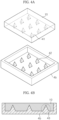
- FIG. 4A is an enlarged view of portion B of FIG. 2 and shows an external appearance before coupling of the second acoustic absorption layer 4b having tetrahedral inserts and the controller 10 having recesses corresponding to the inserts
- FIG. 4B is an enlarged view of portion B of FIG. 2 and shows a cross section after coupling of the second acoustic absorption layer 4b having the tetrahedral inserts and the controller 10 having the recesses corresponding to the inserts.
- the second acoustic absorption layer 4b may include tetrahedral inserts 42 and the controller 10 may include recesses 41 corresponding to the tetrahedral inserts 42.
- the tetrahedral inserts 42 and the recesses 41 corresponding to the inserts 42 may have the same size and the same direction to realize female-male engagement 43.
- the inserts 42 and the recesses 41 may be packaged to coincide with each other in terms of size and direction, realizing the tetrahedral female-male engagement 43.
- the controller 10 achieves an increased heat radiation area such that heat generated in the controller 10 may be transferred to the inserts 42 of the second acoustic absorption layer 4b through the recesses 41 of the controller 10 with high heat radiation efficiency.
- the second acoustic absorption layer 4b surrounds and packages the controller 10 to reduce damage to the controller 10, which may enhance durability of the ultrasonic diagnostic instrument 1.
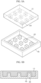
- FIG. 5A is an enlarged view of portion B of FIG. 2 and shows an external appearance before coupling of the second acoustic absorption layer 4b having hexahedral inserts 45 and the controller 10 having recesses 44 corresponding to the inserts 45
- FIG. 5B is an enlarged view of portion B of FIG. 2 and shows a cross section after coupling of the second acoustic absorption layer 4b having the hexahedral inserts 45 and the controller 10 having the recesses 44 corresponding to the inserts 45.
- the second acoustic absorption layer 4b may include the hexahedral inserts 45 and the controller 10 may include recesses 44 corresponding to the hexahedral inserts 45.
- the hexahedral inserts 45 and the recesses 44 corresponding to the inserts 45 may have the same size and the same direction to realize female-male engagement 46.
- the inserts 45 and the recesses 44 may be packaged to coincide with each other in terms of size and direction, realizing the hexahedral female-male engagement 46.
- the controller 10 achieves an increased heat radiation area such that heat generated in the controller 10 may be transferred to the inserts 45 of the second acoustic absorption layer 4b through the recesses 44 of the controller 10 with high heat radiation efficiency.
- the second acoustic absorption layer 4b surrounds and packages the controller 10 to reduce damage to the controller 10, which may enhance durability of the ultrasonic diagnostic instrument 1.
- FIG. 6A is an enlarged view of portion B of FIG. 2 and shows an external appearance before coupling of the second acoustic absorption layer 4b having semispherical inserts 48 and the controller 10 having recesses 47 corresponding to the inserts 48
- FIG. 6B is an enlarged view of portion B of FIG. 2 and shows a cross section after coupling of the second acoustic absorption layer 4b having the semispherical inserts 48 and the controller 10 having the recesses 47 corresponding to the inserts 48.
- the second acoustic absorption layer 4b may include the semispherical inserts 48 and the controller 10 may include the recesses 47 corresponding to the semispherical inserts 48.
- the semispherical inserts 48 and the recesses 47 corresponding to the inserts 48 may have the same size and the same direction to realize female-male engagement 49.
- the inserts 48 and the recesses 47 may be packaged to coincide with each other in terms of size and direction, realizing the semispherical female-male engagement 49.
- the controller 10 achieves an increased heat radiation area such that heat generated in the controller 10 may be transferred to the inserts 48 of the second acoustic absorption layer 4b through the recesses 47 of the controller 10 with high heat radiation efficiency.
- the second acoustic absorption layer 4b surrounds and packages the controller 10 to reduce damage to the controller 10, which may enhance durability of the ultrasonic diagnostic instrument 1.
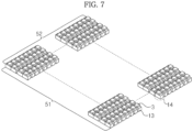
- transducers 3 in the form of a 2D matrix array according to one embodiment will be described with reference to FIG. 7 .
- FIG. 7 shows an external appearance of the ultrasonic diagnostic instrument 1 in which the transducers 3 are arranged in a 2D matrix array (144 x 72).
- a transducer module 14 includes one transducer 3 and one switching element 13 to control the transducer 3, and a plurality of transducer modules 14 may be arranged in a 2D matrix array as exemplarily shown in FIG. 7 .
- transducer modules 14 may be arranged in an abscissa 51 of the array and 72 transducer modules 14 may be arranged in an ordinate 52 of the array.
- the transducer modules 14 are arranged in a 2D matrix of 144 x 72, and a total of 10368 transducer modules 14 may be arranged.
- the 2D matrix array is not limited to the matrix of 144 x 72, but is one example of the array of the transducer modules 14.
- the transducer modules 14 may take the form of a linear array, a convex array, or a concave array.
- the ultrasonic diagnostic instrument including the controller having the recesses and the second acoustic absorption layer having the inserts according to one embodiment will be described with reference to FIG. 8 .
- FIG. 8 is a flowchart of a method of manufacturing the ultrasonic diagnostic instrument.
- a matching layer is first provided (S10), and a transducer to transmit and receive ultrasonic waves is provided at a lower surface of the matching layer (S20). Then, after providing a first acoustic absorption layer having conductivity at a lower surface of the transducer (S30), a controller including a semiconductor switching element is formed (S40), and recesses are formed in a lower surface of the controller by back-grinding, dicing, etching, or the like (S50).
- the controller is provided at a lower surface of the first acoustic absorption layer (S60). Then, inserts corresponding to the recesses of the controller are formed at an upper surface of the second acoustic absorption layer by back-grinding, dicing, etching, or the like (S70). Finally, as the second acoustic absorption layer is provided at the lower surface of the controller (S80), the ultrasonic diagnostic instrument may be manufactured.
- an ultrasonic diagnostic instrument and a method of manufacturing the ultrasonic diagnostic instrument, it may be possible to enhance radiation efficiency of heat generated in a transducer and to increase durability of the ultrasonic diagnostic instrument.
Description
- Embodiments of the present invention relate to an ultrasonic diagnostic instrument, which achieves enhanced heat dissipation efficiency via an increased surface area of a radiator and also achieves increased durability with a packaging structure thereof, and a method of manufacturing the ultrasonic diagnostic instrument.
- An ultrasonic diagnostic instrument is a device that transmits an ultrasonic signal from the body surface of a subject to an internal body region, and acquires tomography of soft tissues or blood flow in a non-invasive manner using information regarding the reflected ultrasonic signal (ultrasound echo signal). As compared to other diagnostic imaging apparatuses, such as an X-ray diagnostic apparatus, X-ray Computerized Tomography (CT) scanner, Magnetic Resonance Imaging (MRI) apparatus, nuclear medicine diagnostic apparatus, etc., the ultrasonic diagnostic instrument is small and cheap, enables real-time image display, and exhibits high safety due to less X-ray exposure. Owing to these advantages, the ultrasonic diagnostic instrument has been widely used for diagnosis of heart, abdomen, urinary, and ob-gyn diseases.
- A typical ultrasonic diagnostic instrument, to acquire an ultrasonic image of a subject, includes a transducer to transmit an ultrasonic signal to the subject and to receive an ultrasound echo signal reflected from the subject.
- More specifically, the ultrasonic diagnostic instrument may include a transducer to implement inter-conversion between an electrical signal and an acoustic signal via vibration of a piezoelectric material, a matching layer to reduce a difference in acoustic impedances between the transducer and the subject to allow ultrasonic waves generated in the transducer to be transmitted to the subject to the maximum extent, a lens layer to collimate the ultrasonic waves moving forward of the transducer on a specific point, and an acoustic absorption layer to prevent the ultrasonic waves from moving rearward of the transducer to prevent image distortion.
- Recently, smaller size and higher performance of the transducer included in the ultrasonic diagnostic instrument causes generation of heat, and therefore research into heat transfer to prevent heat from being transferred forward of the ultrasonic diagnostic instrument or research into cooling of the ultrasonic diagnostic instrument has been conducted.
- The
US 2013/315035 A1 describes an ultrasound transducer including an array of acoustic elements, an integrated circuit, and an interposer. The interposer includes conductive elements for electrically connecting the acoustic elements to the integrated circuit. The conductive elements are electrically connected to the integrated circuit. Solder is engaged between the acoustic elements and the conductive elements of the interposer such that the conductive elements of the interposer are electrically connected to the acoustic elements through the solder. -
EP 2 382 619 A2 - In accordance with one embodiment, an ultrasonic diagnostic instrument according to
claim 1 is provided. - The insert may have one shape among cylindrical, semispherical, tetrahedral, pentagonal, and hexahedral shapes.
- The at least one transducer includes a plurality of transducers in the form of a matrix array, a linear array, a convex array, or a concave array.
- The controller includes a plurality of semiconductor elements to control the respective transducers, and the semiconductor elements take the form of a matrix array, a linear array, a convex array, or a concave array.
- A width of each semiconductor element is equal to or greater than a width of a corresponding one of the transducers controlled by the semiconductor element, and may be equal to or less than the sum of a width of a corresponding one of the transducers controlled by the semiconductor element and a gap between the corresponding transducer and another transducer located at one side thereof.
- A thickness of each semiconductor element may have a value acquired by dividing the wavelength of ultrasonic waves generated by a corresponding one of the transducers controlled by the semiconductor element by an even number.
- In accordance with another embodiment, a method of manufacturing an ultrasonic diagnostic instrument according to
claim 7 is provided. - These and/or other aspects of the invention will become more readily appreciated from the following description of the embodiments, taken in conjunction with the accompanying drawings of which:
-
FIG. 1 is a sectional view of an acoustic module in an ultrasonic diagnostic instrument; -
FIG. 2 is a sectional view of an ultrasonic diagnostic instrument before coupling of an acoustic module and a controller according to one embodiment; -
FIG. 3 is an enlarged sectional view of portion A ofFIG. 2 , showing the ultrasonic diagnostic instrument after coupling of the acoustic module and the controller according to the embodiment; -
FIG. 4A is a perspective view showing an external appearance before coupling of a second acoustic absorption layer having tetrahedral inserts and a controller having recesses corresponding to the inserts according to one embodiment; -
FIG. 4B is a sectional view showing a cross section after coupling of the second acoustic absorption layer having the tetrahedral inserts and the controller having the recesses corresponding to the inserts according to the embodiment ofFIG. 4A ; -
FIG. 5A is a perspective view showing an external appearance before coupling of a second acoustic absorption layer having hexahedral inserts and a controller having recesses corresponding to the inserts according to one embodiment; -
FIG. 5B is a sectional view showing a cross section after coupling of the second acoustic absorption layer having the hexahedral inserts and the controller having the recesses corresponding to the inserts according to the embodiment ofFIG. 5A ; -
FIG. 6A is a perspective view showing an external appearance before coupling of a second acoustic absorption layer having semispherical inserts and a controller having recesses corresponding to the inserts according to one embodiment; -
FIG. 6B is a sectional view showing a cross section after coupling of the second acoustic absorption layer having the semispherical inserts and the controller having the recesses corresponding to the inserts according to the embodiment ofFIG. 6A ; -
FIG. 7 is a perspective view showing an external appearance of an ultrasonic diagnostic instrument in which transducers are arranged in 2-dimensional matrix (144 x 72) according to one embodiment; and -
FIG. 8 is a flowchart of a method of manufacturing an ultrasonic diagnostic instrument according to one embodiment. - Reference will now be made in detail to the embodiments of the present invention, examples of which are illustrated in the accompanying drawings, to allow those skilled in the art to easily understand and reproduce the embodiments of the present invention. In the following description of the embodiments of the present invention, a detailed description of known functions or configurations incorporated herein will be omitted when it may make the subject matter of the disclosure rather unclear.
- It should be noted and understood that there can be improvements and modifications made of the present invention described in detail below without departing from the scope of the invention as set forth in the accompanying claims.
- Hereinafter, one embodiment of an ultrasonic
diagnostic instrument 1 will be described with reference to the accompanying drawings. -
FIG. 1 is a sectional view of anacoustic module 8 in the ultrasonicdiagnostic instrument 1. - As exemplarily shown in
FIG. 1 , the ultrasonicdiagnostic instrument 1 may include anacoustic module 8 composed of atransducer 3, anacoustic absorption layer 4 disposed at a lower surface of thetransducer 3, and amatching layer 2 disposed at an upper surface of thetransducer 3, a protective layer 5 covering an upper surface and a portion of a side surface of theacoustic module 8, and alens layer 6 covering an upper surface and a side surface of the protective layer 5. - Examples of ultrasonic transducers may include a magnetostrictive ultrasonic transducer using magnetostrictive effects of a magnetic material, a capacitive micromachined ultrasonic transducer to transmit and receive ultrasonic waves using vibration of several hundred or thousand micromachined thin films, and a piezoelectric ultrasonic transducer using piezoelectric effects of a piezoelectric material. Hereinafter, a piezoelectric ultrasonic transducer will be described as one embodiment of the transducer.
- Piezoelectric effects or inverse piezoelectric effects are effects in which voltage is generated when mechanical pressure is applied to a material, and mechanical deformation occurs upon voltage application. A material having the effects may be referred to as a piezoelectric material. That is, a piezoelectric material may convert electrical energy into mechanical vibration energy or vice versa.
- The
transducer 3 may be formed of a piezoelectric material. Thus, when an electrical signal is applied to the ultrasonicdiagnostic instrument 1, thetransducer 3 may convert the electrical signal into mechanical vibration, thereby generating ultrasonic waves. - The piezoelectric material constituting the
transducer 3 may include lead zirconate titanate (PZT) ceramics, PZMT single-crystals made of magnesium niobate and lead zirconate titanate solid solution, or PZNT single-crystals made of zinc-niobate and lead zirconate titanate solid solution. Naturally, various other materials to convert an electrical signal into mechanical vibration may be used as one example of the piezoelectric material constituting thetransducer 3. - In addition, the
transducer 3 may be arranged in a single-layer or in a stack of multiple layers. Generally, thetransducer 3 in the form of a stack may be more advantageous in terms of impedance and voltage adjustment, thus achieving high energy conversion efficiency and tender spectrums. Naturally, various other structures in consideration of the performance of thetransducer 3 may be used as one example of the structure of thetransducer 3. - The
acoustic absorption layer 4 may be installed to the lower surface of thetransducer 3 to absorb ultrasonic waves generated in and moving rearward of thetransducer 3, thereby preventing ultrasonic waves from moving rearward of thetransducer 3. Consequently, theacoustic absorption layer 4 may prevent image distortion. Theacoustic absorption layer 4 may be formed in multiple layers to increase attenuation or prevention of ultrasonic waves. Naturally, various structures to increase attenuation or prevention of ultrasonic waves may be used as one example of the structure of theacoustic absorption layer 4. - The
matching layer 2 may be installed at the upper surface of thetransducer 3. Thematching layer 2 may reduce a difference in acoustic impedances between thetransducer 3 and a subject to match the acoustic impedances of thetransducer 3 and the subject with each other, thereby allowing ultrasonic waves generated in thetransducer 3 to be efficiently transmitted to the subject. To this end, the impedance of thematching layer 2 may have a median value between the acoustic impedance of thetransducer 3 and the acoustic impedance of the subject. - The
matching layer 2 may be formed of glass or a resin. Naturally, various other materials to match the acoustic impedances of thetransducer 3 and the subject with each other may be used as one example of a constituent material of thematching layer 2. - In addition, the
matching layer 2 may include a plurality of matchinglayers 2 to ensure stepwise variation of acoustic impedance from thetransducer 3 to the subject, and the matching layers 2 may be formed of different materials. Naturally, various other structures to ensure stepwise variation of acoustic impedance may be used as one example of the structure of thematching layer 2. - The
transducer 3 and thematching layer 2 may be processed into a 2-dimensional (2D) matrix array by dicing, or may be processed into a 1D matrix array. - The protective layer 5 may be installed to cover an upper surface of the
matching layer 2 and a portion of the side surface of theacoustic module 8. The protective layer 5 may include a chemical shield to protect internal elements from water and medicines used for disinfection. The chemical shield may be formed by coating or depositing a conductive material on a surface of a moisture-proof and chemical-resistant film. For example, the chemical shield may be formed by implementing Parylene coating of a polymer film on the upper surface of thematching layer 2 and a portion of the side surface of theacoustic module 8. In another example, the chemical shield may be formed by sputtering on a surface of a polymer film. - In addition, the protective layer 5 may include a Radio Frequency (RF) shield to prevent leakage of RF waves from the
transducer 3 as well as introduction of an external RF signal. Naturally, various other configurations to prevent introduction/leakage of RF components may be used as one example of a constituent configuration of the protective layer 5. - The
lens layer 6 may be installed to cover the upper surface and the side surface of the protective layer 5. Thelens layer 6 may be formed of a low-attenuation material to prevent attenuation of an ultrasonic signal generated in thetransducer 3. For example, thelens layer 6 may be formed of a low viscosity epoxy resin, such as DER322 or DEH24. Naturally, various other materials to prevent attenuation of an ultrasonic signal may be used as one example of a constituent material of thelens layer 6. As a result of forming thelens layer 6 of a low-attenuation material, it may be possible to enhance the sensitivity of an ultrasonic signal. - Moreover, as a result of installing the
lens layer 6 to cover a portion of the side surface of theacoustic module 8, i.e. a portion of the outer surface of theacoustic module 8, it may be possible to reduce crosstalk. - Hereinafter, the ultrasonic
diagnostic instrument 1 including theacoustic module 8 and acontroller 10 according to one embodiment will be described with reference toFIGS. 2 and3 . -
FIG. 2 is a sectional view of the ultrasonicdiagnostic instrument 1 before coupling of theacoustic module 8 and acontroller 10, andFIG. 3 is an enlarged sectional view of portion A ofFIG. 2 , showing the cross section of the ultrasonicdiagnostic instrument 1 after coupling of theacoustic module 8 and thecontroller 10. - The ultrasonic
diagnostic instrument 1 may include thelens layer 6, afirst connector 7 and asecond connector 20 and includes thematching layer 2, thetransducer 3, a firstacoustic absorption layer 4a, thecontroller 10, and a secondacoustic absorption layer 4b. - The
lens layer 6 may prevent attenuation of an ultrasonic signal generated in thetransducer 3, thereby enhancing the sensitivity of the ultrasonic signal. Thelens layer 6 may be installed to cover thematching layer 2, may be installed to cover the matching layer and thetransducer 3, or may be installed to cover the matching layer, thetransducer 3, and the firstacoustic absorption layer 4a. Functions, materials, and the like of thelens layer 6 may be equal to or different from those of thelens layer 6 as mentioned above with reference toFIG. 1 . - The
matching layer 2 may reduce a difference in acoustic impedances between thetransducer 3 and the subject to match the acoustic impedances of thetransducer 3 and the subject with each other, thereby allowing ultrasonic waves generated in thetransducer 3 to be efficiently transmitted to the subject. - In addition, the
matching layer 2 may include afirst matching layer 2a and asecond matching layer 2b. More specifically, thematching layer 2 may be divided into thefirst matching layer 2a and thesecond matching layer 2b based on a region of the subject to be diagnosed, characteristics of the ultrasonicdiagnostic instrument 1 including thetransducer 3, and frequencies of ultrasonic waves to be transmitted or received. Thefirst matching layer 2a and thesecond matching layer 2b may be formed of different materials to achieve different acoustic impedances, or may be formed of the same material. Functions, shapes, materials, and the like of thematching layer 2 may be equal to or different from those of thematching layer 2 as mentioned above with reference toFIG. 1 . - The
transducer 3 may convert an applied electrical signal into mechanical vibration to transmit ultrasonic waves, or may convert mechanical vibration into an electrical signal by receiving an ultrasonic signal reflected from a region to be diagnosed. Functions, shapes, materials, and the like of thetransducer 3 may be equal to or different from those of thetransducer 3 as mentioned above with reference toFIG. 1 . - The first
acoustic absorption layer 4a is installed to the lower surface of thetransducer 3 to absorb ultrasonic waves generated in and moving rearward of thetransducer 3, thereby preventing ultrasonic waves from moving rearward of thetransducer 3. In addition, the firstacoustic absorption layer 4a may receive a control signal of thecontroller 10 through thesecond connector 20, and then transmit the control signal to thetransducer 3 through thefirst connector 7, to enable generation of ultrasonic waves in thetransducer 3. - To transmit a control signal of the
controller 10 to thetransducer 3, the firstacoustic absorption layer 4a may be formed of a conductive material. For example, the firstacoustic absorption layer 4a may be formed of tungsten (WC) having high impedance, thus amplifying a control signal of thecontroller 10 to transmit the amplified control signal to thetransducer 3. Naturally, various other materials to transmit a control signal of thecontroller 10 to thetransducer 3 may be used as one example of a constituent material of the firstacoustic absorption layer 4a. - In addition, the impedance of the first
acoustic absorption layer 4a may vary based on frequencies of ultrasonic waves to be transmitted or received and the structure of the firstacoustic absorption layer 4a, but may have an approximate value of 100Ω. - The
first connector 7 may be located between thetransducer 3 and the firstacoustic absorption layer 4a to physically and electrically connect thetransducer 3 and the firstacoustic absorption layer 4a to each other. - More specifically, the
first connector 7 may physically couple thetransducer 3 and the firstacoustic absorption layer 4a to each other to transmit vibration of thetransducer 3 to the firstacoustic absorption layer 4a, which enables attenuation of vibration by the firstacoustic absorption layer 4a. In addition, thefirst connector 7 may electrically couple thetransducer 3 and the firstacoustic absorption layer 4a to each other to transmit a control signal of thecontroller 10 to thetransducer 3 for generation of ultrasonic waves and to transmit an electrical signal, converted from mechanical vibration by thetransducer 3, to thecontroller 10. - In addition, although the
first connector 7 may be formed of epoxy, naturally, various other materials to physically and electrically connect thetransducer 3 and the firstacoustic absorption layer 4a to each other may be used as one example of a constituent material of thefirst connector 7. - The
controller 10 may be located between thesecond connector 20 and the secondacoustic absorption layer 4b to transmit a control signal to thetransducer 3 to enable generation of ultrasonic waves in thetransducer 3, or to receive an electrical signal, converted from mechanical vibration, i.e. an ultrasonic signal reflected from a region to be diagnosed by thetransducer 3. - More specifically, the
controller 10 may independently process an external input signal or an electrical signal from thetransducer 3, may convert a received signal, processed by an external system, into a control signal for generation of ultrasonic signals to transmit the control signal to thetransducer 3, or may transmit an electrical signal, received from thetransducer 3, to an external system. - In the case of independently processing an external input signal or an electrical signal of the
transducer 3, thecontroller 10 may include a central processing unit and a graphics processing unit. - The central processing unit included in the
controller 10 may be a microprocessor. The microprocessor is a processing unit in which an arithmetic logic unit, a register, a program counter, a command decoder, a control circuit, or the like is mounted on at least one silicon chip. The central processing unit may generate a control signal to control operation of thetransducer 3, and transmit the generated control signal to thetransducer 3 through the firstacoustic absorption layer 4a. In addition, the central processing unit may receive an electrical signal converted by thetransducer 3 and transmit the electrical signal to the graphics processing unit. According to embodiments not forming part of the invention, the central processing unit may generate a signal to control a switching element used to control each ofplural transducers 3 in the form of an array, and transmit the generated control signal to the switching element. - The graphics processing unit is a processing unit that processes graphics information. The graphics processing unit may assist a graphics processing function of the central processing unit, or may implement graphics processing alone. The graphics processing unit may convert an ultrasonic signal received by the
transducer 3 into an ultrasonic image signal, or may process a signal to display operation of the ultrasonicdiagnostic instrument 1. - The
controller 10 includes a plurality of switching elements. - The switching elements control the
respective transducers 3 arranged in the form of a matrix array, a linear array, a convex array, or a concave array. The switching element controls onetransducer 3, and in embodiments not forming part of the invention two or more transducers. - The switching element may be formed of a semiconductor material to control the
transducers 3. In this case, the semiconductor material may be silicon (Si), or compounds of silicon (Si), sapphire, germanium, quartz, and glass. Naturally, various other materials to control thetransducers 3 may be used as one example of a semiconductor material. - Accordingly, when the central processing unit of the
controller 10 applies an operational signal having a threshold voltage or more to the switching element, the switching element formed of a semiconductor material, as exemplarily shown inFIG. 3 , may be divided into anactive area 11 and aninactive area 12. Thereby, thecontroller 10 may transmit a control signal to thetransducer 3 through the switching element. - A width W2; 31 of the switching element is equal to or greater than a width W1; 32 of the
corresponding transducer 3 controlled by the switching element (W1≤ W2), and may be equal to or less than a pitch P; 33 of the transducer 3 (W2≤ P). Here, the pitch P is the sum of the width of thetransducer 3 controlled by the switching element and a gap between thecorresponding transducer 3 and another transducer located at one side thereof. In addition, the width W2; 31 of the switching element is equal to or greater than the width W1; 32 of thecorresponding transducer 3 controlled by the switching element and may be equal to or less than the pitch P; 33 of the transducer 3 (W1≤ W2≤ P). - In addition, a thickness H; 34 of the switching element may be a value acquired by dividing the wavelength of ultrasonic waves generated in the
transducer 3 by an even number. For example, the thickness H; 34 of the switching element may be one of 1/2, 1/4, 1/8, and 1/16 of the wavelength of generated ultrasonic waves (H=λ /2, λ /4, λ /8, or λ /16). - The
controller 10 has recesses formed in the lower surface thereof. The recesses may correspond to inserts of the secondacoustic absorption layer 4b that will be described hereinafter. The recesses of thecontroller 10 may be formed by back-grinding, dicing, or etching. - More specifically, back-grinding is a process of removing an unnecessary film on a rear surface of a wafer and grinding an unnecessarily thick rear surface to reduce resistance and increase thermal conductivity. Dicing is a cutting process using a diamond blade on a high-speed rotating spindle. Etching is a process of removing an oxide film not coated with a photoresist film.
- Naturally, various other methods may be used to form the recesses in the lower surface of the
controller 10. - Shapes, and the like of the recesses will be described below in detail.
- The
second connector 20 may be located between the firstacoustic absorption layer 4a and thecontroller 10 to electrically connect the firstacoustic absorption layer 4a and thecontroller 10 to each other. Thesecond connector 20 may include apillar 21 formed of copper (Cu), abump 22 formed of tin (Sn) and silver (Ag), and apad 23 formed of gold (Au). - The
second connector 20 may electrically connect the firstacoustic absorption layer 4a and thecontroller 10 to each other by directly fusing the same to each other in a flip-chip manner using a lower electrode pattern, without an additional connection structure, such as a meal lead wire, or an intermediate medium, such as a ball grid array (BGA). More specifically, after thecopper pillar 21 and thebump 22, attached to the firstacoustic absorption layer 4a, are located above thepad 23 attached to thecontroller 10, pressure is applied to the firstacoustic absorption layer 4a in a direction toward thecontroller 10 or heat is applied to thebump 22 until thebump 22 covers thepad 23 located at the upper surface of thecontroller 10. In this way, thesecond connector 20 may electrically connect the firstacoustic absorption layer 4a and thecontroller 10 to each other. - The second
acoustic absorption layer 4b is installed to the lower surface of thecontroller 10 to absorb ultrasonic waves moving rearward of thetransducer 3, not absorbed by the firstacoustic absorption layer 4a. In addition, the secondacoustic absorption layer 4b may prevent forward transfer of heat generated in thecontroller 10, thereby causing rearward transfer of heat. - The second
acoustic absorption layer 4b may be formed of a thermally conductive material and an acoustic absorption material, and has inserts. - More specifically, the thermally conductive material may include a Carbon Nano Tube (CNT) as a carbon allotrope, graphene, or graphite, or may include a composite of a carbon allotrope and a metal. The composite of the carbon allotrope and the metal may be produced by fusing each component, or may be produced by alternately stacking the carbon allotrope and the metal in respective layers. Naturally, various other materials to increase thermal conductivity may be used as one example of the thermally conductive material.
- The acoustic absorption material may function to adjust acoustic impedance and attenuation constant. In a representative example, the acoustic absorption material may include epoxy. Naturally, various other materials to adjust acoustic impedance and attenuation constant may be used as one example of the acoustic absorption material. In addition, the acoustic absorption material may have different acoustic impedances per layer.
- The second
acoustic absorption layer 4b may be formed of at least one of the thermally conductive material and the acoustic absorption material, and may be formed by alternately arranging the thermally conductive material and the acoustic absorption material. Naturally, various other arrangements to adjust thermal conductivity, acoustic impedance, and attenuation constant of the secondacoustic absorption layer 4b may be used as one example of the arrangement of the secondacoustic absorption layer 4b. - The second
acoustic absorption layer 4b has the inserts formed at the upper surface thereof. The inserts have any one shape among cylindrical, semispherical, tetrahedral, pentagonal, and hexagonal shapes. Naturally, various other shapes to radiate heat generated in thecontroller 10 may be used as one example of the inserts of the secondacoustic absorption layer 4b. The inserts of the secondacoustic absorption layer 4b may be formed by back-grinding, dicing, or etching. Naturally, various other methods may be used as one example of a method of forming the inserts at the upper surface of the secondacoustic absorption layer 4b. - Shapes, and the like of the inserts will be described below in detail.
- The thermally conductive material of the second
acoustic absorption layer 4b may have a square-wave shape, a cylindrical shape, or the like, and an empty space of the secondacoustic absorption layer 4b may be filled with an acoustic absorption material to provide the ultrasonicdiagnostic instrument 1 with appropriate acoustic impedance. - Accordingly, heat generated in the
controller 10 may be transferred to the recesses formed in the lower surface of thecontroller 10, and then be transferred to the inserts formed at the upper surface of the secondacoustic absorption layer 4b. The heat transferred to the inserts may be radiated while being propagated at the lower surface of the secondacoustic absorption layer 4b through the thermally conductive material. - Hereinafter, a packaging coupling structure of the second
acoustic absorption layer 4b having the inserts and thecontroller 10 having the recesses corresponding to the inserts according to different embodiments will be described with reference toFIGS. 4A to 6B . -
FIG. 4A is an enlarged view of portion B ofFIG. 2 and shows an external appearance before coupling of the secondacoustic absorption layer 4b having tetrahedral inserts and thecontroller 10 having recesses corresponding to the inserts, andFIG. 4B is an enlarged view of portion B ofFIG. 2 and shows a cross section after coupling of the secondacoustic absorption layer 4b having the tetrahedral inserts and thecontroller 10 having the recesses corresponding to the inserts. - As exemplarily shown in
FIG. 4A , the secondacoustic absorption layer 4b may includetetrahedral inserts 42 and thecontroller 10 may includerecesses 41 corresponding to the tetrahedral inserts 42. The tetrahedral inserts 42 and therecesses 41 corresponding to theinserts 42 may have the same size and the same direction to realize female-male engagement 43. - Thus, as exemplarily shown in
FIG. 4B , when the secondacoustic absorption layer 4b and thecontroller 10 are connected to each other, theinserts 42 and therecesses 41 may be packaged to coincide with each other in terms of size and direction, realizing the tetrahedral female-male engagement 43. - In this way, the
controller 10 achieves an increased heat radiation area such that heat generated in thecontroller 10 may be transferred to theinserts 42 of the secondacoustic absorption layer 4b through therecesses 41 of thecontroller 10 with high heat radiation efficiency. In addition, the secondacoustic absorption layer 4b surrounds and packages thecontroller 10 to reduce damage to thecontroller 10, which may enhance durability of the ultrasonicdiagnostic instrument 1. -
FIG. 5A is an enlarged view of portion B ofFIG. 2 and shows an external appearance before coupling of the secondacoustic absorption layer 4b having hexahedral inserts 45 and thecontroller 10 havingrecesses 44 corresponding to theinserts 45, andFIG. 5B is an enlarged view of portion B ofFIG. 2 and shows a cross section after coupling of the secondacoustic absorption layer 4b having the hexahedral inserts 45 and thecontroller 10 having therecesses 44 corresponding to theinserts 45. - As exemplarily shown in
FIG. 5A , the secondacoustic absorption layer 4b may include the hexahedral inserts 45 and thecontroller 10 may includerecesses 44 corresponding to the hexahedral inserts 45. The hexahedral inserts 45 and therecesses 44 corresponding to theinserts 45 may have the same size and the same direction to realize female-male engagement 46. - Thus, as exemplarily shown in
FIG. 5B , when the secondacoustic absorption layer 4b and thecontroller 10 are connected to each other, theinserts 45 and therecesses 44 may be packaged to coincide with each other in terms of size and direction, realizing the hexahedral female-male engagement 46. - In this way, the
controller 10 achieves an increased heat radiation area such that heat generated in thecontroller 10 may be transferred to theinserts 45 of the secondacoustic absorption layer 4b through therecesses 44 of thecontroller 10 with high heat radiation efficiency. In addition, the secondacoustic absorption layer 4b surrounds and packages thecontroller 10 to reduce damage to thecontroller 10, which may enhance durability of the ultrasonicdiagnostic instrument 1. -
FIG. 6A is an enlarged view of portion B ofFIG. 2 and shows an external appearance before coupling of the secondacoustic absorption layer 4b having semispherical inserts 48 and thecontroller 10 havingrecesses 47 corresponding to theinserts 48, andFIG. 6B is an enlarged view of portion B ofFIG. 2 and shows a cross section after coupling of the secondacoustic absorption layer 4b having the semispherical inserts 48 and thecontroller 10 having therecesses 47 corresponding to theinserts 48. - As exemplarily shown in
FIG. 6A , the secondacoustic absorption layer 4b may include the semispherical inserts 48 and thecontroller 10 may include therecesses 47 corresponding to the semispherical inserts 48. The semispherical inserts 48 and therecesses 47 corresponding to theinserts 48 may have the same size and the same direction to realize female-male engagement 49. - Thus, as exemplarily shown in
FIG. 6B , when the secondacoustic absorption layer 4b and thecontroller 10 are connected to each other, theinserts 48 and therecesses 47 may be packaged to coincide with each other in terms of size and direction, realizing the semispherical female-male engagement 49. - In this way, the
controller 10 achieves an increased heat radiation area such that heat generated in thecontroller 10 may be transferred to theinserts 48 of the secondacoustic absorption layer 4b through therecesses 47 of thecontroller 10 with high heat radiation efficiency. In addition, the secondacoustic absorption layer 4b surrounds and packages thecontroller 10 to reduce damage to thecontroller 10, which may enhance durability of the ultrasonicdiagnostic instrument 1. - Hereinafter, the
transducers 3 in the form of a 2D matrix array according to one embodiment will be described with reference toFIG. 7 . -
FIG. 7 shows an external appearance of the ultrasonicdiagnostic instrument 1 in which thetransducers 3 are arranged in a 2D matrix array (144 x 72). - A
transducer module 14 includes onetransducer 3 and oneswitching element 13 to control thetransducer 3, and a plurality oftransducer modules 14 may be arranged in a 2D matrix array as exemplarily shown inFIG. 7 . - More specifically, 144
transducer modules 14 may be arranged in anabscissa 51 of the array and 72transducer modules 14 may be arranged in anordinate 52 of the array. Thus, thetransducer modules 14 are arranged in a 2D matrix of 144 x 72, and a total of 10368transducer modules 14 may be arranged. - However, the 2D matrix array is not limited to the matrix of 144 x 72, but is one example of the array of the
transducer modules 14. Thetransducer modules 14 may take the form of a linear array, a convex array, or a concave array. - Hereinafter, a method of manufacturing the ultrasonic diagnostic instrument including the controller having the recesses and the second acoustic absorption layer having the inserts according to one embodiment will be described with reference to
FIG. 8 . -
FIG. 8 is a flowchart of a method of manufacturing the ultrasonic diagnostic instrument. - A matching layer is first provided (S10), and a transducer to transmit and receive ultrasonic waves is provided at a lower surface of the matching layer (S20). Then, after providing a first acoustic absorption layer having conductivity at a lower surface of the transducer (S30), a controller including a semiconductor switching element is formed (S40), and recesses are formed in a lower surface of the controller by back-grinding, dicing, etching, or the like (S50).
- The controller is provided at a lower surface of the first acoustic absorption layer (S60). Then, inserts corresponding to the recesses of the controller are formed at an upper surface of the second acoustic absorption layer by back-grinding, dicing, etching, or the like (S70). Finally, as the second acoustic absorption layer is provided at the lower surface of the controller (S80), the ultrasonic diagnostic instrument may be manufactured.
- As is apparent from the above description, according to an ultrasonic diagnostic instrument and a method of manufacturing the ultrasonic diagnostic instrument, it may be possible to enhance radiation efficiency of heat generated in a transducer and to increase durability of the ultrasonic diagnostic instrument.
Claims (10)
- An ultrasonic diagnostic instrument (1) comprising:a matching layer (2);at least one transducer (3) provided at a lower surface of the matching layer (2) to generate ultrasonic waves;a first acoustic absorption layer (4a) provided at a lower surface of the transducer (3) to transmit an ultrasonic wave generation signal to the transducer (3);a controller (10) provided at a lower surface of the first acoustic absorption layer (4a) to control operation of the transducer (3), the controller (10) having a recess formed in a lower surface thereof; anda second acoustic absorption layer (4b) provided at a lower surface of the controller (10) and having an insert formed at an upper surface thereof, the insert corresponding to the recess of the controller (10) and absorbs ultrasonic waves moving rearward of the transducer (3),wherein the at least one transducer (3) includes a plurality of transducers in the form of a matrix array, a linear array, a convex array, or a concave array,wherein the controller (10) includes a plurality of switching elements (13) to control the respective transducers (3), and the switching elements (13) take the form of a matrix array, a linear array, a convex array, or a concave array andwherein a width of each switching element (13) is equal to or greater than a width of a corresponding one of the transducers (3) controlled by the switching element (13).
- The instrument according to claim 1, wherein the first acoustic absorption layer (4a) includes an electrically conductive material.
- The instrument according to claim 1, wherein the second acoustic absorption layer (4b) includes a carbon allotrope, or a composite of a carbon allotrope and a metal.
- The instrument according to claim 1, wherein the insert has one shape among cylindrical, semispherical, tetrahedral, pentagonal, and hexahedral shapes.
- The instrument according to claim 1, wherein the width of each switching element (13) is equal to or less than the sum of the width of a corresponding one of the transducers (3) controlled by the switching element (13) and a gap between the corresponding transducer and another transducer (3) located at one side thereof.
- The instrument according to claim 1, wherein a thickness of each switching element (13) has a value acquired by dividing the wavelength of ultrasonic waves generated by a corresponding one of the transducers (3) controlled by the switching element (13) by an even number.
- A method of manufacturing an ultrasonic diagnostic instrument (1), the method comprising:providing a matching layer (2);providing at least one transducer (3) at a lower surface of the matching layer (2);providing a first acoustic absorption layer (4a) at a lower surface of the transducer (3);forming a recess in a lower surface of a controller (10);providing the controller (10) at a lower surface of the first acoustic absorption layer (4a);forming an insert at an upper surface of a second acoustic absorption layer (4b), the insert corresponding to the recess of the controller (10); andproviding the second acoustic absorption layer (4b) at the lower surface of the controller (10),wherein the second acoustic absorption layer (4b) absorbs ultrasonic waves moving rearward of the transducer (3),arranging a plurality of transducers (3) in the form of a matrix array, a linear array, a convex array, or a concave array; andforming the controller such that the controller (10) includes a plurality of switching elements (13) to control the respective transducers (3),wherein a width of the switching element (13) is equal to or greater than a width of the transducer (3) controlled by the switching element (13).
- The method according to claim 7, wherein the insert formed at the upper surface of the second acoustic absorption layer (4b) has one shape among cylindrical, semispherical, tetrahedral, pentagonal, and hexahedral shapes.
- The method according to claim 7, wherein the width of each switching element (13) is equal to or less than the sum of the width of a corresponding one of the transducers (3) controlled by the switching element (13) and a gap between the corresponding transducer and another transducer (3) located at one side thereof.
- The method according to claim 7, wherein a thickness of each switching element (13) has a value acquired by dividing the wavelength of ultrasonic waves generated by a corresponding one of the transducers (3) controlled by the switching element (13) by an even number.
Applications Claiming Priority (1)
| Application Number | Priority Date | Filing Date | Title |
|---|---|---|---|
| KR1020130152167A KR101613413B1 (en) | 2013-12-09 | 2013-12-09 | Ultrasonic diagnostic instrument and manufacturing method thereof |
Publications (3)
| Publication Number | Publication Date |
|---|---|
| EP2881937A2 EP2881937A2 (en) | 2015-06-10 |
| EP2881937A3 EP2881937A3 (en) | 2015-10-07 |
| EP2881937B1 true EP2881937B1 (en) | 2023-08-09 |
Family
ID=51585010
Family Applications (1)
| Application Number | Title | Priority Date | Filing Date |
|---|---|---|---|
| EP14185778.9A Active EP2881937B1 (en) | 2013-12-09 | 2014-09-22 | Ultrasonic diagnostic instrument and manufacturing method thereof |
Country Status (4)
| Country | Link |
|---|---|
| US (1) | US9642597B2 (en) |
| EP (1) | EP2881937B1 (en) |
| KR (1) | KR101613413B1 (en) |
| CN (1) | CN104688267B (en) |
Families Citing this family (7)
| Publication number | Priority date | Publication date | Assignee | Title |
|---|---|---|---|---|
| JP5923539B2 (en) * | 2014-03-20 | 2016-05-24 | 富士フイルム株式会社 | Ultrasonic probe |
| KR102373132B1 (en) * | 2014-12-26 | 2022-03-11 | 삼성메디슨 주식회사 | An ultrasonic probe apparatus and an ultrasonic imaging apparatus using the same |
| DE102016119824A1 (en) * | 2015-10-19 | 2017-04-20 | Sound Solutions International Co., Ltd. | Ultrasound lens for receiver application |
| JP2017080132A (en) * | 2015-10-29 | 2017-05-18 | セイコーエプソン株式会社 | Ultrasonic device, ultrasonic probe, electronic apparatus and ultrasonic imaging device |
| KR20180096298A (en) * | 2017-02-21 | 2018-08-29 | 삼성메디슨 주식회사 | Ultrasonic probe |
| CN110201872B (en) * | 2019-06-17 | 2021-08-27 | 京东方科技集团股份有限公司 | Detection panel, display device, detection panel driving method and manufacturing method |
| KR102332081B1 (en) * | 2019-07-05 | 2021-12-01 | 고려대학교 산학협력단 | Portable Imaging Device integrating ultrasound and nuclear medicine |
Citations (3)
| Publication number | Priority date | Publication date | Assignee | Title |
|---|---|---|---|---|
| US5160870A (en) * | 1990-06-25 | 1992-11-03 | Carson Paul L | Ultrasonic image sensing array and method |
| US20030114760A1 (en) * | 2001-12-19 | 2003-06-19 | Robinson Andrew L. | Micromachined ultrasound transducer and method for fabricating same |
| EP2382619A2 (en) * | 2008-12-23 | 2011-11-02 | Koninklijke Philips Electronics N.V. | Integrated circuit with spurious acoustic mode suppression and method of manufacture thereof |
Family Cites Families (11)
| Publication number | Priority date | Publication date | Assignee | Title |
|---|---|---|---|---|
| US5629906A (en) * | 1995-02-15 | 1997-05-13 | Hewlett-Packard Company | Ultrasonic transducer |
| US6865140B2 (en) * | 2003-03-06 | 2005-03-08 | General Electric Company | Mosaic arrays using micromachined ultrasound transducers |
| CN1969763A (en) * | 2004-06-15 | 2007-05-30 | 株式会社东芝 | Acoustic backing composition, ultrasonic probe, and ultrasonic diagnostic apparatus |
| JP4319644B2 (en) * | 2004-06-15 | 2009-08-26 | 株式会社東芝 | Acoustic backing composition, ultrasonic probe, and ultrasonic diagnostic apparatus |
| JP2007282743A (en) | 2006-04-14 | 2007-11-01 | Toshiba Corp | Ultrasonic probe, manufacturing method for ultrasonic probe, and ultrasonic diagnosing apparatus |
| KR101018626B1 (en) * | 2008-07-22 | 2011-03-03 | 주식회사 휴먼스캔 | Ultrasonic probe having a heat sink |
| KR101137261B1 (en) | 2009-03-18 | 2012-04-20 | 삼성메디슨 주식회사 | Probe for ultrasonic diagnostic apparatus and manufacturing method thereof |
| US8232705B2 (en) | 2010-07-09 | 2012-07-31 | General Electric Company | Thermal transfer and acoustic matching layers for ultrasound transducer |
| JP5435751B2 (en) * | 2011-03-03 | 2014-03-05 | 富士フイルム株式会社 | Ultrasonic diagnostic apparatus, ultrasonic transmission / reception method, and ultrasonic transmission / reception program |
| US20130170321A1 (en) * | 2011-12-28 | 2013-07-04 | General Electric Company | Systems and methods for controlling transducer pulse transitions in ultrasound imaging |
| US9180490B2 (en) * | 2012-05-22 | 2015-11-10 | General Electric Company | Ultrasound transducer and method for manufacturing an ultrasound transducer |
-
2013
- 2013-12-09 KR KR1020130152167A patent/KR101613413B1/en active IP Right Grant
-
2014
- 2014-09-22 EP EP14185778.9A patent/EP2881937B1/en active Active
- 2014-11-10 US US14/537,717 patent/US9642597B2/en active Active
- 2014-12-09 CN CN201410749398.9A patent/CN104688267B/en active Active
Patent Citations (3)
| Publication number | Priority date | Publication date | Assignee | Title |
|---|---|---|---|---|
| US5160870A (en) * | 1990-06-25 | 1992-11-03 | Carson Paul L | Ultrasonic image sensing array and method |
| US20030114760A1 (en) * | 2001-12-19 | 2003-06-19 | Robinson Andrew L. | Micromachined ultrasound transducer and method for fabricating same |
| EP2382619A2 (en) * | 2008-12-23 | 2011-11-02 | Koninklijke Philips Electronics N.V. | Integrated circuit with spurious acoustic mode suppression and method of manufacture thereof |
Also Published As
| Publication number | Publication date |
|---|---|
| CN104688267B (en) | 2019-04-26 |
| KR20150066748A (en) | 2015-06-17 |
| US20150157292A1 (en) | 2015-06-11 |
| US9642597B2 (en) | 2017-05-09 |
| EP2881937A2 (en) | 2015-06-10 |
| EP2881937A3 (en) | 2015-10-07 |
| CN104688267A (en) | 2015-06-10 |
| KR101613413B1 (en) | 2016-04-19 |
Similar Documents
| Publication | Publication Date | Title |
|---|---|---|
| EP2881937B1 (en) | Ultrasonic diagnostic instrument and manufacturing method thereof | |
| US7405510B2 (en) | Thermally enhanced piezoelectric element | |
| KR20150006519A (en) | Ultrasound Probe and Manufacturing Method thereof | |
| US20180028159A1 (en) | Rearward acoustic diffusion for ultrasound-on-a-chip transducer array | |
| KR101354604B1 (en) | Ultrasound Probe and Manufacturing Method thereof | |
| US8378557B2 (en) | Thermal transfer and acoustic matching layers for ultrasound transducer | |
| US11432800B2 (en) | Handheld ultrasound imager | |
| CN108459085B (en) | Ultrasonic probe | |
| KR101354605B1 (en) | Ultrasound Probe and Manufacturing Method thereof | |
| US8237335B2 (en) | Thermally enhanced ultrasound transducer means | |
| JP7358475B2 (en) | Thermal conductive layer for temperature drop on the transducer surface | |
| KR20150025383A (en) | Probe for ultrasonic diagnostic apparatus | |
| EP3510934A1 (en) | Ultrasonic probe | |
| KR20160084255A (en) | Ultrasound Probe and Manufacturing Method thereof | |
| US11806191B2 (en) | Phased array transducers and wafer scale manufacturing for making the same | |
| EP3811872B1 (en) | Ultrasound probe with improved thermal management | |
| KR101586297B1 (en) | Ultrasound Probe and Manufacturing Method thereof | |
| KR20200010863A (en) | Ultrasound prove array and fabrication method of thereof | |
| KR20180056979A (en) | Ultrasound transducer having convex-concave surface by using non-stackable flexible printed circuit board and manufacturing method therefor |
Legal Events
| Date | Code | Title | Description |
|---|---|---|---|
| PUAI | Public reference made under article 153(3) epc to a published international application that has entered the european phase |
Free format text: ORIGINAL CODE: 0009012 |
|
| 17P | Request for examination filed |
Effective date: 20140922 |
|
| AK | Designated contracting states |
Kind code of ref document: A2 Designated state(s): AL AT BE BG CH CY CZ DE DK EE ES FI FR GB GR HR HU IE IS IT LI LT LU LV MC MK MT NL NO PL PT RO RS SE SI SK SM TR |
|
| AX | Request for extension of the european patent |
Extension state: BA ME |
|
| PUAL | Search report despatched |
Free format text: ORIGINAL CODE: 0009013 |
|
| AK | Designated contracting states |
Kind code of ref document: A3 Designated state(s): AL AT BE BG CH CY CZ DE DK EE ES FI FR GB GR HR HU IE IS IT LI LT LU LV MC MK MT NL NO PL PT RO RS SE SI SK SM TR |
|
| AX | Request for extension of the european patent |
Extension state: BA ME |
|
| RIC1 | Information provided on ipc code assigned before grant |
Ipc: G10K 11/02 20060101AFI20150902BHEP |
|
| R17P | Request for examination filed (corrected) |
Effective date: 20160406 |
|
| RBV | Designated contracting states (corrected) |
Designated state(s): AL AT BE BG CH CY CZ DE DK EE ES FI FR GB GR HR HU IE IS IT LI LT LU LV MC MK MT NL NO PL PT RO RS SE SI SK SM TR |
|
| STAA | Information on the status of an ep patent application or granted ep patent |
Free format text: STATUS: EXAMINATION IS IN PROGRESS |
|
| STAA | Information on the status of an ep patent application or granted ep patent |
Free format text: STATUS: EXAMINATION IS IN PROGRESS |
|
| 17Q | First examination report despatched |
Effective date: 20201110 |
|
| STAA | Information on the status of an ep patent application or granted ep patent |
Free format text: STATUS: EXAMINATION IS IN PROGRESS |
|
| REG | Reference to a national code |
Ref country code: DE Ref legal event code: R079 Ref document number: 602014087893 Country of ref document: DE Free format text: PREVIOUS MAIN CLASS: G10K0011020000 Ipc: A61B0008000000 Ipc: A61B0008000000 |
|
| GRAP | Despatch of communication of intention to grant a patent |
Free format text: ORIGINAL CODE: EPIDOSNIGR1 |
|
| STAA | Information on the status of an ep patent application or granted ep patent |
Free format text: STATUS: GRANT OF PATENT IS INTENDED |
|
| RIC1 | Information provided on ipc code assigned before grant |
Ipc: B06B 1/02 20060101ALN20230215BHEP Ipc: G10K 11/02 20060101ALI20230215BHEP Ipc: B06B 1/06 20060101ALI20230215BHEP Ipc: A61B 8/00 20060101AFI20230215BHEP |
|
| INTG | Intention to grant announced |
Effective date: 20230301 |
|
| GRAS | Grant fee paid |
Free format text: ORIGINAL CODE: EPIDOSNIGR3 |
|
| GRAA | (expected) grant |
Free format text: ORIGINAL CODE: 0009210 |
|
| STAA | Information on the status of an ep patent application or granted ep patent |
Free format text: STATUS: THE PATENT HAS BEEN GRANTED |
|
| AK | Designated contracting states |
Kind code of ref document: B1 Designated state(s): AL AT BE BG CH CY CZ DE DK EE ES FI FR GB GR HR HU IE IS IT LI LT LU LV MC MK MT NL NO PL PT RO RS SE SI SK SM TR |
|
| REG | Reference to a national code |
Ref country code: GB Ref legal event code: FG4D |
|
| REG | Reference to a national code |
Ref country code: CH Ref legal event code: EP |
|
| REG | Reference to a national code |
Ref country code: IE Ref legal event code: FG4D |
|
| REG | Reference to a national code |
Ref country code: DE Ref legal event code: R096 Ref document number: 602014087893 Country of ref document: DE |
|
| REG | Reference to a national code |
Ref country code: LT Ref legal event code: MG9D |
|
| PGFP | Annual fee paid to national office [announced via postgrant information from national office to epo] |
Ref country code: FR Payment date: 20230927 Year of fee payment: 10 |
|
| REG | Reference to a national code |
Ref country code: NL Ref legal event code: MP Effective date: 20230809 |
|
| REG | Reference to a national code |
Ref country code: AT Ref legal event code: MK05 Ref document number: 1596556 Country of ref document: AT Kind code of ref document: T Effective date: 20230809 |
|
| PG25 | Lapsed in a contracting state [announced via postgrant information from national office to epo] |
Ref country code: GR Free format text: LAPSE BECAUSE OF FAILURE TO SUBMIT A TRANSLATION OF THE DESCRIPTION OR TO PAY THE FEE WITHIN THE PRESCRIBED TIME-LIMIT Effective date: 20231110 |
|
| PG25 | Lapsed in a contracting state [announced via postgrant information from national office to epo] |
Ref country code: IS Free format text: LAPSE BECAUSE OF FAILURE TO SUBMIT A TRANSLATION OF THE DESCRIPTION OR TO PAY THE FEE WITHIN THE PRESCRIBED TIME-LIMIT Effective date: 20231209 |
|
| PG25 | Lapsed in a contracting state [announced via postgrant information from national office to epo] |
Ref country code: SE Free format text: LAPSE BECAUSE OF FAILURE TO SUBMIT A TRANSLATION OF THE DESCRIPTION OR TO PAY THE FEE WITHIN THE PRESCRIBED TIME-LIMIT Effective date: 20230809 Ref country code: RS Free format text: LAPSE BECAUSE OF FAILURE TO SUBMIT A TRANSLATION OF THE DESCRIPTION OR TO PAY THE FEE WITHIN THE PRESCRIBED TIME-LIMIT Effective date: 20230809 Ref country code: PT Free format text: LAPSE BECAUSE OF FAILURE TO SUBMIT A TRANSLATION OF THE DESCRIPTION OR TO PAY THE FEE WITHIN THE PRESCRIBED TIME-LIMIT Effective date: 20231211 Ref country code: NO Free format text: LAPSE BECAUSE OF FAILURE TO SUBMIT A TRANSLATION OF THE DESCRIPTION OR TO PAY THE FEE WITHIN THE PRESCRIBED TIME-LIMIT Effective date: 20231109 Ref country code: NL Free format text: LAPSE BECAUSE OF FAILURE TO SUBMIT A TRANSLATION OF THE DESCRIPTION OR TO PAY THE FEE WITHIN THE PRESCRIBED TIME-LIMIT Effective date: 20230809 Ref country code: LV Free format text: LAPSE BECAUSE OF FAILURE TO SUBMIT A TRANSLATION OF THE DESCRIPTION OR TO PAY THE FEE WITHIN THE PRESCRIBED TIME-LIMIT Effective date: 20230809 Ref country code: LT Free format text: LAPSE BECAUSE OF FAILURE TO SUBMIT A TRANSLATION OF THE DESCRIPTION OR TO PAY THE FEE WITHIN THE PRESCRIBED TIME-LIMIT Effective date: 20230809 Ref country code: IS Free format text: LAPSE BECAUSE OF FAILURE TO SUBMIT A TRANSLATION OF THE DESCRIPTION OR TO PAY THE FEE WITHIN THE PRESCRIBED TIME-LIMIT Effective date: 20231209 Ref country code: HR Free format text: LAPSE BECAUSE OF FAILURE TO SUBMIT A TRANSLATION OF THE DESCRIPTION OR TO PAY THE FEE WITHIN THE PRESCRIBED TIME-LIMIT Effective date: 20230809 Ref country code: GR Free format text: LAPSE BECAUSE OF FAILURE TO SUBMIT A TRANSLATION OF THE DESCRIPTION OR TO PAY THE FEE WITHIN THE PRESCRIBED TIME-LIMIT Effective date: 20231110 Ref country code: FI Free format text: LAPSE BECAUSE OF FAILURE TO SUBMIT A TRANSLATION OF THE DESCRIPTION OR TO PAY THE FEE WITHIN THE PRESCRIBED TIME-LIMIT Effective date: 20230809 Ref country code: AT Free format text: LAPSE BECAUSE OF FAILURE TO SUBMIT A TRANSLATION OF THE DESCRIPTION OR TO PAY THE FEE WITHIN THE PRESCRIBED TIME-LIMIT Effective date: 20230809 |
|
| PGFP | Annual fee paid to national office [announced via postgrant information from national office to epo] |
Ref country code: IT Payment date: 20231025 Year of fee payment: 10 Ref country code: DE Payment date: 20231020 Year of fee payment: 10 |
|
| PG25 | Lapsed in a contracting state [announced via postgrant information from national office to epo] |
Ref country code: PL Free format text: LAPSE BECAUSE OF FAILURE TO SUBMIT A TRANSLATION OF THE DESCRIPTION OR TO PAY THE FEE WITHIN THE PRESCRIBED TIME-LIMIT Effective date: 20230809 |