EP2881937B1 - Ultraschall-Diagnoseinstrument und Herstellungsverfahren dafür - Google Patents
Ultraschall-Diagnoseinstrument und Herstellungsverfahren dafür Download PDFInfo
- Publication number
- EP2881937B1 EP2881937B1 EP14185778.9A EP14185778A EP2881937B1 EP 2881937 B1 EP2881937 B1 EP 2881937B1 EP 14185778 A EP14185778 A EP 14185778A EP 2881937 B1 EP2881937 B1 EP 2881937B1
- Authority
- EP
- European Patent Office
- Prior art keywords
- transducer
- controller
- absorption layer
- acoustic absorption
- switching element
- Prior art date
- Legal status (The legal status is an assumption and is not a legal conclusion. Google has not performed a legal analysis and makes no representation as to the accuracy of the status listed.)
- Active
Links
Images


Classifications
-
- A—HUMAN NECESSITIES
- A61—MEDICAL OR VETERINARY SCIENCE; HYGIENE
- A61B—DIAGNOSIS; SURGERY; IDENTIFICATION
- A61B8/00—Diagnosis using ultrasonic, sonic or infrasonic waves
-
- G—PHYSICS
- G10—MUSICAL INSTRUMENTS; ACOUSTICS
- G10K—SOUND-PRODUCING DEVICES; METHODS OR DEVICES FOR PROTECTING AGAINST, OR FOR DAMPING, NOISE OR OTHER ACOUSTIC WAVES IN GENERAL; ACOUSTICS NOT OTHERWISE PROVIDED FOR
- G10K11/00—Methods or devices for transmitting, conducting or directing sound in general; Methods or devices for protecting against, or for damping, noise or other acoustic waves in general
- G10K11/02—Mechanical acoustic impedances; Impedance matching, e.g. by horns; Acoustic resonators
-
- A—HUMAN NECESSITIES
- A61—MEDICAL OR VETERINARY SCIENCE; HYGIENE
- A61B—DIAGNOSIS; SURGERY; IDENTIFICATION
- A61B8/00—Diagnosis using ultrasonic, sonic or infrasonic waves
- A61B8/44—Constructional features of the ultrasonic, sonic or infrasonic diagnostic device
- A61B8/4444—Constructional features of the ultrasonic, sonic or infrasonic diagnostic device related to the probe
-
- A—HUMAN NECESSITIES
- A61—MEDICAL OR VETERINARY SCIENCE; HYGIENE
- A61B—DIAGNOSIS; SURGERY; IDENTIFICATION
- A61B8/00—Diagnosis using ultrasonic, sonic or infrasonic waves
- A61B8/44—Constructional features of the ultrasonic, sonic or infrasonic diagnostic device
- A61B8/4483—Constructional features of the ultrasonic, sonic or infrasonic diagnostic device characterised by features of the ultrasound transducer
- A61B8/4488—Constructional features of the ultrasonic, sonic or infrasonic diagnostic device characterised by features of the ultrasound transducer the transducer being a phased array
-
- A—HUMAN NECESSITIES
- A61—MEDICAL OR VETERINARY SCIENCE; HYGIENE
- A61B—DIAGNOSIS; SURGERY; IDENTIFICATION
- A61B8/00—Diagnosis using ultrasonic, sonic or infrasonic waves
- A61B8/54—Control of the diagnostic device
-
- B—PERFORMING OPERATIONS; TRANSPORTING
- B06—GENERATING OR TRANSMITTING MECHANICAL VIBRATIONS IN GENERAL
- B06B—METHODS OR APPARATUS FOR GENERATING OR TRANSMITTING MECHANICAL VIBRATIONS OF INFRASONIC, SONIC, OR ULTRASONIC FREQUENCY, e.g. FOR PERFORMING MECHANICAL WORK IN GENERAL
- B06B1/00—Methods or apparatus for generating mechanical vibrations of infrasonic, sonic, or ultrasonic frequency
- B06B1/02—Methods or apparatus for generating mechanical vibrations of infrasonic, sonic, or ultrasonic frequency making use of electrical energy
- B06B1/06—Methods or apparatus for generating mechanical vibrations of infrasonic, sonic, or ultrasonic frequency making use of electrical energy operating with piezoelectric effect or with electrostriction
- B06B1/0607—Methods or apparatus for generating mechanical vibrations of infrasonic, sonic, or ultrasonic frequency making use of electrical energy operating with piezoelectric effect or with electrostriction using multiple elements
- B06B1/0622—Methods or apparatus for generating mechanical vibrations of infrasonic, sonic, or ultrasonic frequency making use of electrical energy operating with piezoelectric effect or with electrostriction using multiple elements on one surface
-
- G—PHYSICS
- G01—MEASURING; TESTING
- G01N—INVESTIGATING OR ANALYSING MATERIALS BY DETERMINING THEIR CHEMICAL OR PHYSICAL PROPERTIES
- G01N29/00—Investigating or analysing materials by the use of ultrasonic, sonic or infrasonic waves; Visualisation of the interior of objects by transmitting ultrasonic or sonic waves through the object
- G01N29/22—Details, e.g. general constructional or apparatus details
- G01N29/24—Probes
-
- B—PERFORMING OPERATIONS; TRANSPORTING
- B06—GENERATING OR TRANSMITTING MECHANICAL VIBRATIONS IN GENERAL
- B06B—METHODS OR APPARATUS FOR GENERATING OR TRANSMITTING MECHANICAL VIBRATIONS OF INFRASONIC, SONIC, OR ULTRASONIC FREQUENCY, e.g. FOR PERFORMING MECHANICAL WORK IN GENERAL
- B06B1/00—Methods or apparatus for generating mechanical vibrations of infrasonic, sonic, or ultrasonic frequency
- B06B1/02—Methods or apparatus for generating mechanical vibrations of infrasonic, sonic, or ultrasonic frequency making use of electrical energy
- B06B1/0292—Electrostatic transducers, e.g. electret-type
-
- B—PERFORMING OPERATIONS; TRANSPORTING
- B06—GENERATING OR TRANSMITTING MECHANICAL VIBRATIONS IN GENERAL
- B06B—METHODS OR APPARATUS FOR GENERATING OR TRANSMITTING MECHANICAL VIBRATIONS OF INFRASONIC, SONIC, OR ULTRASONIC FREQUENCY, e.g. FOR PERFORMING MECHANICAL WORK IN GENERAL
- B06B2201/00—Indexing scheme associated with B06B1/0207 for details covered by B06B1/0207 but not provided for in any of its subgroups
- B06B2201/70—Specific application
- B06B2201/76—Medical, dental
-
- Y—GENERAL TAGGING OF NEW TECHNOLOGICAL DEVELOPMENTS; GENERAL TAGGING OF CROSS-SECTIONAL TECHNOLOGIES SPANNING OVER SEVERAL SECTIONS OF THE IPC; TECHNICAL SUBJECTS COVERED BY FORMER USPC CROSS-REFERENCE ART COLLECTIONS [XRACs] AND DIGESTS
- Y10—TECHNICAL SUBJECTS COVERED BY FORMER USPC
- Y10T—TECHNICAL SUBJECTS COVERED BY FORMER US CLASSIFICATION
- Y10T29/00—Metal working
- Y10T29/49—Method of mechanical manufacture
- Y10T29/49002—Electrical device making
- Y10T29/49005—Acoustic transducer
Definitions
- Embodiments of the present invention relate to an ultrasonic diagnostic instrument, which achieves enhanced heat dissipation efficiency via an increased surface area of a radiator and also achieves increased durability with a packaging structure thereof, and a method of manufacturing the ultrasonic diagnostic instrument.
- An ultrasonic diagnostic instrument is a device that transmits an ultrasonic signal from the body surface of a subject to an internal body region, and acquires tomography of soft tissues or blood flow in a non-invasive manner using information regarding the reflected ultrasonic signal (ultrasound echo signal).
- the ultrasonic diagnostic instrument is small and cheap, enables real-time image display, and exhibits high safety due to less X-ray exposure. Owing to these advantages, the ultrasonic diagnostic instrument has been widely used for diagnosis of heart, abdomen, urinary, and ob-gyn diseases.
- a typical ultrasonic diagnostic instrument to acquire an ultrasonic image of a subject, includes a transducer to transmit an ultrasonic signal to the subject and to receive an ultrasound echo signal reflected from the subject.
- the ultrasonic diagnostic instrument may include a transducer to implement inter-conversion between an electrical signal and an acoustic signal via vibration of a piezoelectric material, a matching layer to reduce a difference in acoustic impedances between the transducer and the subject to allow ultrasonic waves generated in the transducer to be transmitted to the subject to the maximum extent, a lens layer to collimate the ultrasonic waves moving forward of the transducer on a specific point, and an acoustic absorption layer to prevent the ultrasonic waves from moving rearward of the transducer to prevent image distortion.
- a transducer to implement inter-conversion between an electrical signal and an acoustic signal via vibration of a piezoelectric material
- a matching layer to reduce a difference in acoustic impedances between the transducer and the subject to allow ultrasonic waves generated in the transducer to be transmitted to the subject to the maximum extent
- a lens layer to collimate the ultrasonic waves moving forward of the
- the US 2013/315035 A1 describes an ultrasound transducer including an array of acoustic elements, an integrated circuit, and an interposer.
- the interposer includes conductive elements for electrically connecting the acoustic elements to the integrated circuit.
- the conductive elements are electrically connected to the integrated circuit.
- Solder is engaged between the acoustic elements and the conductive elements of the interposer such that the conductive elements of the interposer are electrically connected to the acoustic elements through the solder.
- EP 2 382 619 A2 discloses acoustic transducers fabricated integrally on an integrated circuit (IC) but not a controller having a plurality of switching elements to control the respective transducers wherein the width of each switching element is equal to or greater than a width of a corresponding one of the transducers controlled by the switching element.
- an ultrasonic diagnostic instrument according to claim 1 is provided.
- the insert may have one shape among cylindrical, semispherical, tetrahedral, pentagonal, and hexahedral shapes.
- the at least one transducer includes a plurality of transducers in the form of a matrix array, a linear array, a convex array, or a concave array.
- the controller includes a plurality of semiconductor elements to control the respective transducers, and the semiconductor elements take the form of a matrix array, a linear array, a convex array, or a concave array.
- a width of each semiconductor element is equal to or greater than a width of a corresponding one of the transducers controlled by the semiconductor element, and may be equal to or less than the sum of a width of a corresponding one of the transducers controlled by the semiconductor element and a gap between the corresponding transducer and another transducer located at one side thereof.
- a thickness of each semiconductor element may have a value acquired by dividing the wavelength of ultrasonic waves generated by a corresponding one of the transducers controlled by the semiconductor element by an even number.
- FIG. 1 is a sectional view of an acoustic module 8 in the ultrasonic diagnostic instrument 1.
- the ultrasonic diagnostic instrument 1 may include an acoustic module 8 composed of a transducer 3, an acoustic absorption layer 4 disposed at a lower surface of the transducer 3, and a matching layer 2 disposed at an upper surface of the transducer 3, a protective layer 5 covering an upper surface and a portion of a side surface of the acoustic module 8, and a lens layer 6 covering an upper surface and a side surface of the protective layer 5.
- an acoustic module 8 composed of a transducer 3, an acoustic absorption layer 4 disposed at a lower surface of the transducer 3, and a matching layer 2 disposed at an upper surface of the transducer 3, a protective layer 5 covering an upper surface and a portion of a side surface of the acoustic module 8, and a lens layer 6 covering an upper surface and a side surface of the protective layer 5.
- ultrasonic transducers may include a magnetostrictive ultrasonic transducer using magnetostrictive effects of a magnetic material, a capacitive micromachined ultrasonic transducer to transmit and receive ultrasonic waves using vibration of several hundred or thousand micromachined thin films, and a piezoelectric ultrasonic transducer using piezoelectric effects of a piezoelectric material.
- a piezoelectric ultrasonic transducer will be described as one embodiment of the transducer.
- Piezoelectric effects or inverse piezoelectric effects are effects in which voltage is generated when mechanical pressure is applied to a material, and mechanical deformation occurs upon voltage application.
- a material having the effects may be referred to as a piezoelectric material. That is, a piezoelectric material may convert electrical energy into mechanical vibration energy or vice versa.
- the transducer 3 may be formed of a piezoelectric material. Thus, when an electrical signal is applied to the ultrasonic diagnostic instrument 1, the transducer 3 may convert the electrical signal into mechanical vibration, thereby generating ultrasonic waves.
- the piezoelectric material constituting the transducer 3 may include lead zirconate titanate (PZT) ceramics, PZMT single-crystals made of magnesium niobate and lead zirconate titanate solid solution, or PZNT single-crystals made of zinc-niobate and lead zirconate titanate solid solution.
- PZT lead zirconate titanate
- PZMT PZMT single-crystals made of magnesium niobate and lead zirconate titanate solid solution
- PZNT single-crystals made of zinc-niobate and lead zirconate titanate solid solution.
- various other materials to convert an electrical signal into mechanical vibration may be used as one example of the piezoelectric material constituting the transducer 3.
- the transducer 3 may be arranged in a single-layer or in a stack of multiple layers. Generally, the transducer 3 in the form of a stack may be more advantageous in terms of impedance and voltage adjustment, thus achieving high energy conversion efficiency and tender spectrums. Naturally, various other structures in consideration of the performance of the transducer 3 may be used as one example of the structure of the transducer 3.
- the acoustic absorption layer 4 may be installed to the lower surface of the transducer 3 to absorb ultrasonic waves generated in and moving rearward of the transducer 3, thereby preventing ultrasonic waves from moving rearward of the transducer 3. Consequently, the acoustic absorption layer 4 may prevent image distortion.
- the acoustic absorption layer 4 may be formed in multiple layers to increase attenuation or prevention of ultrasonic waves. Naturally, various structures to increase attenuation or prevention of ultrasonic waves may be used as one example of the structure of the acoustic absorption layer 4.
- the matching layer 2 may be installed at the upper surface of the transducer 3.
- the matching layer 2 may reduce a difference in acoustic impedances between the transducer 3 and a subject to match the acoustic impedances of the transducer 3 and the subject with each other, thereby allowing ultrasonic waves generated in the transducer 3 to be efficiently transmitted to the subject.
- the impedance of the matching layer 2 may have a median value between the acoustic impedance of the transducer 3 and the acoustic impedance of the subject.
- the matching layer 2 may be formed of glass or a resin. Naturally, various other materials to match the acoustic impedances of the transducer 3 and the subject with each other may be used as one example of a constituent material of the matching layer 2.
- the matching layer 2 may include a plurality of matching layers 2 to ensure stepwise variation of acoustic impedance from the transducer 3 to the subject, and the matching layers 2 may be formed of different materials.
- various other structures to ensure stepwise variation of acoustic impedance may be used as one example of the structure of the matching layer 2.
- the transducer 3 and the matching layer 2 may be processed into a 2-dimensional (2D) matrix array by dicing, or may be processed into a 1D matrix array.
- the protective layer 5 may be installed to cover an upper surface of the matching layer 2 and a portion of the side surface of the acoustic module 8.
- the protective layer 5 may include a chemical shield to protect internal elements from water and medicines used for disinfection.
- the chemical shield may be formed by coating or depositing a conductive material on a surface of a moisture-proof and chemical-resistant film.
- the chemical shield may be formed by implementing Parylene coating of a polymer film on the upper surface of the matching layer 2 and a portion of the side surface of the acoustic module 8.
- the chemical shield may be formed by sputtering on a surface of a polymer film.
- the protective layer 5 may include a Radio Frequency (RF) shield to prevent leakage of RF waves from the transducer 3 as well as introduction of an external RF signal.
- RF Radio Frequency
- various other configurations to prevent introduction/leakage of RF components may be used as one example of a constituent configuration of the protective layer 5.
- the lens layer 6 may be installed to cover the upper surface and the side surface of the protective layer 5.
- the lens layer 6 may be formed of a low-attenuation material to prevent attenuation of an ultrasonic signal generated in the transducer 3.
- the lens layer 6 may be formed of a low viscosity epoxy resin, such as DER322 or DEH24.
- various other materials to prevent attenuation of an ultrasonic signal may be used as one example of a constituent material of the lens layer 6.
- the lens layer 6 may be possible to reduce crosstalk.
- the ultrasonic diagnostic instrument 1 including the acoustic module 8 and a controller 10 according to one embodiment will be described with reference to FIGS. 2 and 3 .
- FIG. 2 is a sectional view of the ultrasonic diagnostic instrument 1 before coupling of the acoustic module 8 and a controller 10
- FIG. 3 is an enlarged sectional view of portion A of FIG. 2 , showing the cross section of the ultrasonic diagnostic instrument 1 after coupling of the acoustic module 8 and the controller 10.
- the ultrasonic diagnostic instrument 1 may include the lens layer 6, a first connector 7 and a second connector 20 and includes the matching layer 2, the transducer 3, a first acoustic absorption layer 4a, the controller 10, and a second acoustic absorption layer 4b.
- the lens layer 6 may prevent attenuation of an ultrasonic signal generated in the transducer 3, thereby enhancing the sensitivity of the ultrasonic signal.
- the lens layer 6 may be installed to cover the matching layer 2, may be installed to cover the matching layer and the transducer 3, or may be installed to cover the matching layer, the transducer 3, and the first acoustic absorption layer 4a. Functions, materials, and the like of the lens layer 6 may be equal to or different from those of the lens layer 6 as mentioned above with reference to FIG. 1 .
- the matching layer 2 may reduce a difference in acoustic impedances between the transducer 3 and the subject to match the acoustic impedances of the transducer 3 and the subject with each other, thereby allowing ultrasonic waves generated in the transducer 3 to be efficiently transmitted to the subject.
- the matching layer 2 may include a first matching layer 2a and a second matching layer 2b. More specifically, the matching layer 2 may be divided into the first matching layer 2a and the second matching layer 2b based on a region of the subject to be diagnosed, characteristics of the ultrasonic diagnostic instrument 1 including the transducer 3, and frequencies of ultrasonic waves to be transmitted or received.
- the first matching layer 2a and the second matching layer 2b may be formed of different materials to achieve different acoustic impedances, or may be formed of the same material. Functions, shapes, materials, and the like of the matching layer 2 may be equal to or different from those of the matching layer 2 as mentioned above with reference to FIG. 1 .
- the transducer 3 may convert an applied electrical signal into mechanical vibration to transmit ultrasonic waves, or may convert mechanical vibration into an electrical signal by receiving an ultrasonic signal reflected from a region to be diagnosed. Functions, shapes, materials, and the like of the transducer 3 may be equal to or different from those of the transducer 3 as mentioned above with reference to FIG. 1 .
- the first acoustic absorption layer 4a is installed to the lower surface of the transducer 3 to absorb ultrasonic waves generated in and moving rearward of the transducer 3, thereby preventing ultrasonic waves from moving rearward of the transducer 3.
- the first acoustic absorption layer 4a may receive a control signal of the controller 10 through the second connector 20, and then transmit the control signal to the transducer 3 through the first connector 7, to enable generation of ultrasonic waves in the transducer 3.
- the first acoustic absorption layer 4a may be formed of a conductive material.
- the first acoustic absorption layer 4a may be formed of tungsten (WC) having high impedance, thus amplifying a control signal of the controller 10 to transmit the amplified control signal to the transducer 3.
- WC tungsten
- various other materials to transmit a control signal of the controller 10 to the transducer 3 may be used as one example of a constituent material of the first acoustic absorption layer 4a.
- the impedance of the first acoustic absorption layer 4a may vary based on frequencies of ultrasonic waves to be transmitted or received and the structure of the first acoustic absorption layer 4a, but may have an approximate value of 100 ⁇ .
- the first connector 7 may be located between the transducer 3 and the first acoustic absorption layer 4a to physically and electrically connect the transducer 3 and the first acoustic absorption layer 4a to each other.
- the first connector 7 may physically couple the transducer 3 and the first acoustic absorption layer 4a to each other to transmit vibration of the transducer 3 to the first acoustic absorption layer 4a, which enables attenuation of vibration by the first acoustic absorption layer 4a.
- the first connector 7 may electrically couple the transducer 3 and the first acoustic absorption layer 4a to each other to transmit a control signal of the controller 10 to the transducer 3 for generation of ultrasonic waves and to transmit an electrical signal, converted from mechanical vibration by the transducer 3, to the controller 10.
- first connector 7 may be formed of epoxy, naturally, various other materials to physically and electrically connect the transducer 3 and the first acoustic absorption layer 4a to each other may be used as one example of a constituent material of the first connector 7.
- the controller 10 may be located between the second connector 20 and the second acoustic absorption layer 4b to transmit a control signal to the transducer 3 to enable generation of ultrasonic waves in the transducer 3, or to receive an electrical signal, converted from mechanical vibration, i.e. an ultrasonic signal reflected from a region to be diagnosed by the transducer 3.
- the controller 10 may independently process an external input signal or an electrical signal from the transducer 3, may convert a received signal, processed by an external system, into a control signal for generation of ultrasonic signals to transmit the control signal to the transducer 3, or may transmit an electrical signal, received from the transducer 3, to an external system.
- the controller 10 may include a central processing unit and a graphics processing unit.
- the central processing unit included in the controller 10 may be a microprocessor.
- the microprocessor is a processing unit in which an arithmetic logic unit, a register, a program counter, a command decoder, a control circuit, or the like is mounted on at least one silicon chip.
- the central processing unit may generate a control signal to control operation of the transducer 3, and transmit the generated control signal to the transducer 3 through the first acoustic absorption layer 4a.
- the central processing unit may receive an electrical signal converted by the transducer 3 and transmit the electrical signal to the graphics processing unit.
- the central processing unit may generate a signal to control a switching element used to control each of plural transducers 3 in the form of an array, and transmit the generated control signal to the switching element.
- the graphics processing unit is a processing unit that processes graphics information.
- the graphics processing unit may assist a graphics processing function of the central processing unit, or may implement graphics processing alone.
- the graphics processing unit may convert an ultrasonic signal received by the transducer 3 into an ultrasonic image signal, or may process a signal to display operation of the ultrasonic diagnostic instrument 1.
- the controller 10 includes a plurality of switching elements.
- the switching elements control the respective transducers 3 arranged in the form of a matrix array, a linear array, a convex array, or a concave array.
- the switching element controls one transducer 3, and in embodiments not forming part of the invention two or more transducers.
- the switching element may be formed of a semiconductor material to control the transducers 3.
- the semiconductor material may be silicon (Si), or compounds of silicon (Si), sapphire, germanium, quartz, and glass.
- Si silicon
- Si compounds of silicon
- sapphire germanium
- quartz quartz
- various other materials to control the transducers 3 may be used as one example of a semiconductor material.
- the switching element formed of a semiconductor material may be divided into an active area 11 and an inactive area 12.
- the controller 10 may transmit a control signal to the transducer 3 through the switching element.
- a width W2; 31 of the switching element is equal to or greater than a width W1; 32 of the corresponding transducer 3 controlled by the switching element (W1 ⁇ W2), and may be equal to or less than a pitch P; 33 of the transducer 3 (W2 ⁇ P).
- the pitch P is the sum of the width of the transducer 3 controlled by the switching element and a gap between the corresponding transducer 3 and another transducer located at one side thereof.
- the width W2; 31 of the switching element is equal to or greater than the width W1; 32 of the corresponding transducer 3 controlled by the switching element and may be equal to or less than the pitch P; 33 of the transducer 3 (W1 ⁇ W2 ⁇ P).
- a thickness H; 34 of the switching element may be a value acquired by dividing the wavelength of ultrasonic waves generated in the transducer 3 by an even number.
- the controller 10 has recesses formed in the lower surface thereof.
- the recesses may correspond to inserts of the second acoustic absorption layer 4b that will be described hereinafter.
- the recesses of the controller 10 may be formed by back-grinding, dicing, or etching.
- back-grinding is a process of removing an unnecessary film on a rear surface of a wafer and grinding an unnecessarily thick rear surface to reduce resistance and increase thermal conductivity.
- Dicing is a cutting process using a diamond blade on a high-speed rotating spindle.
- Etching is a process of removing an oxide film not coated with a photoresist film.
- the second connector 20 may be located between the first acoustic absorption layer 4a and the controller 10 to electrically connect the first acoustic absorption layer 4a and the controller 10 to each other.
- the second connector 20 may include a pillar 21 formed of copper (Cu), a bump 22 formed of tin (Sn) and silver (Ag), and a pad 23 formed of gold (Au).
- the second connector 20 may electrically connect the first acoustic absorption layer 4a and the controller 10 to each other by directly fusing the same to each other in a flip-chip manner using a lower electrode pattern, without an additional connection structure, such as a meal lead wire, or an intermediate medium, such as a ball grid array (BGA). More specifically, after the copper pillar 21 and the bump 22, attached to the first acoustic absorption layer 4a, are located above the pad 23 attached to the controller 10, pressure is applied to the first acoustic absorption layer 4a in a direction toward the controller 10 or heat is applied to the bump 22 until the bump 22 covers the pad 23 located at the upper surface of the controller 10. In this way, the second connector 20 may electrically connect the first acoustic absorption layer 4a and the controller 10 to each other.
- BGA ball grid array
- the second acoustic absorption layer 4b is installed to the lower surface of the controller 10 to absorb ultrasonic waves moving rearward of the transducer 3, not absorbed by the first acoustic absorption layer 4a.
- the second acoustic absorption layer 4b may prevent forward transfer of heat generated in the controller 10, thereby causing rearward transfer of heat.
- the second acoustic absorption layer 4b may be formed of a thermally conductive material and an acoustic absorption material, and has inserts.
- the thermally conductive material may include a Carbon Nano Tube (CNT) as a carbon allotrope, graphene, or graphite, or may include a composite of a carbon allotrope and a metal.
- CNT Carbon Nano Tube
- the composite of the carbon allotrope and the metal may be produced by fusing each component, or may be produced by alternately stacking the carbon allotrope and the metal in respective layers.
- various other materials to increase thermal conductivity may be used as one example of the thermally conductive material.
- the acoustic absorption material may function to adjust acoustic impedance and attenuation constant.
- the acoustic absorption material may include epoxy.
- various other materials to adjust acoustic impedance and attenuation constant may be used as one example of the acoustic absorption material.
- the acoustic absorption material may have different acoustic impedances per layer.
- the second acoustic absorption layer 4b may be formed of at least one of the thermally conductive material and the acoustic absorption material, and may be formed by alternately arranging the thermally conductive material and the acoustic absorption material.
- various other arrangements to adjust thermal conductivity, acoustic impedance, and attenuation constant of the second acoustic absorption layer 4b may be used as one example of the arrangement of the second acoustic absorption layer 4b.
- the second acoustic absorption layer 4b has the inserts formed at the upper surface thereof.
- the inserts have any one shape among cylindrical, semispherical, tetrahedral, pentagonal, and hexagonal shapes.
- various other shapes to radiate heat generated in the controller 10 may be used as one example of the inserts of the second acoustic absorption layer 4b.
- the inserts of the second acoustic absorption layer 4b may be formed by back-grinding, dicing, or etching.
- various other methods may be used as one example of a method of forming the inserts at the upper surface of the second acoustic absorption layer 4b.
- the thermally conductive material of the second acoustic absorption layer 4b may have a square-wave shape, a cylindrical shape, or the like, and an empty space of the second acoustic absorption layer 4b may be filled with an acoustic absorption material to provide the ultrasonic diagnostic instrument 1 with appropriate acoustic impedance.
- heat generated in the controller 10 may be transferred to the recesses formed in the lower surface of the controller 10, and then be transferred to the inserts formed at the upper surface of the second acoustic absorption layer 4b.
- the heat transferred to the inserts may be radiated while being propagated at the lower surface of the second acoustic absorption layer 4b through the thermally conductive material.
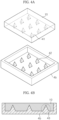
- FIG. 4A is an enlarged view of portion B of FIG. 2 and shows an external appearance before coupling of the second acoustic absorption layer 4b having tetrahedral inserts and the controller 10 having recesses corresponding to the inserts
- FIG. 4B is an enlarged view of portion B of FIG. 2 and shows a cross section after coupling of the second acoustic absorption layer 4b having the tetrahedral inserts and the controller 10 having the recesses corresponding to the inserts.
- the second acoustic absorption layer 4b may include tetrahedral inserts 42 and the controller 10 may include recesses 41 corresponding to the tetrahedral inserts 42.
- the tetrahedral inserts 42 and the recesses 41 corresponding to the inserts 42 may have the same size and the same direction to realize female-male engagement 43.
- the inserts 42 and the recesses 41 may be packaged to coincide with each other in terms of size and direction, realizing the tetrahedral female-male engagement 43.
- the controller 10 achieves an increased heat radiation area such that heat generated in the controller 10 may be transferred to the inserts 42 of the second acoustic absorption layer 4b through the recesses 41 of the controller 10 with high heat radiation efficiency.
- the second acoustic absorption layer 4b surrounds and packages the controller 10 to reduce damage to the controller 10, which may enhance durability of the ultrasonic diagnostic instrument 1.
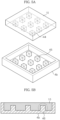
- FIG. 5A is an enlarged view of portion B of FIG. 2 and shows an external appearance before coupling of the second acoustic absorption layer 4b having hexahedral inserts 45 and the controller 10 having recesses 44 corresponding to the inserts 45
- FIG. 5B is an enlarged view of portion B of FIG. 2 and shows a cross section after coupling of the second acoustic absorption layer 4b having the hexahedral inserts 45 and the controller 10 having the recesses 44 corresponding to the inserts 45.
- the second acoustic absorption layer 4b may include the hexahedral inserts 45 and the controller 10 may include recesses 44 corresponding to the hexahedral inserts 45.
- the hexahedral inserts 45 and the recesses 44 corresponding to the inserts 45 may have the same size and the same direction to realize female-male engagement 46.
- the inserts 45 and the recesses 44 may be packaged to coincide with each other in terms of size and direction, realizing the hexahedral female-male engagement 46.
- the controller 10 achieves an increased heat radiation area such that heat generated in the controller 10 may be transferred to the inserts 45 of the second acoustic absorption layer 4b through the recesses 44 of the controller 10 with high heat radiation efficiency.
- the second acoustic absorption layer 4b surrounds and packages the controller 10 to reduce damage to the controller 10, which may enhance durability of the ultrasonic diagnostic instrument 1.
- FIG. 6A is an enlarged view of portion B of FIG. 2 and shows an external appearance before coupling of the second acoustic absorption layer 4b having semispherical inserts 48 and the controller 10 having recesses 47 corresponding to the inserts 48
- FIG. 6B is an enlarged view of portion B of FIG. 2 and shows a cross section after coupling of the second acoustic absorption layer 4b having the semispherical inserts 48 and the controller 10 having the recesses 47 corresponding to the inserts 48.
- the second acoustic absorption layer 4b may include the semispherical inserts 48 and the controller 10 may include the recesses 47 corresponding to the semispherical inserts 48.
- the semispherical inserts 48 and the recesses 47 corresponding to the inserts 48 may have the same size and the same direction to realize female-male engagement 49.
- the inserts 48 and the recesses 47 may be packaged to coincide with each other in terms of size and direction, realizing the semispherical female-male engagement 49.
- the controller 10 achieves an increased heat radiation area such that heat generated in the controller 10 may be transferred to the inserts 48 of the second acoustic absorption layer 4b through the recesses 47 of the controller 10 with high heat radiation efficiency.
- the second acoustic absorption layer 4b surrounds and packages the controller 10 to reduce damage to the controller 10, which may enhance durability of the ultrasonic diagnostic instrument 1.
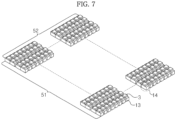
- transducers 3 in the form of a 2D matrix array according to one embodiment will be described with reference to FIG. 7 .
- FIG. 7 shows an external appearance of the ultrasonic diagnostic instrument 1 in which the transducers 3 are arranged in a 2D matrix array (144 x 72).
- a transducer module 14 includes one transducer 3 and one switching element 13 to control the transducer 3, and a plurality of transducer modules 14 may be arranged in a 2D matrix array as exemplarily shown in FIG. 7 .
- transducer modules 14 may be arranged in an abscissa 51 of the array and 72 transducer modules 14 may be arranged in an ordinate 52 of the array.
- the transducer modules 14 are arranged in a 2D matrix of 144 x 72, and a total of 10368 transducer modules 14 may be arranged.
- the 2D matrix array is not limited to the matrix of 144 x 72, but is one example of the array of the transducer modules 14.
- the transducer modules 14 may take the form of a linear array, a convex array, or a concave array.
- the ultrasonic diagnostic instrument including the controller having the recesses and the second acoustic absorption layer having the inserts according to one embodiment will be described with reference to FIG. 8 .
- FIG. 8 is a flowchart of a method of manufacturing the ultrasonic diagnostic instrument.
- a matching layer is first provided (S10), and a transducer to transmit and receive ultrasonic waves is provided at a lower surface of the matching layer (S20). Then, after providing a first acoustic absorption layer having conductivity at a lower surface of the transducer (S30), a controller including a semiconductor switching element is formed (S40), and recesses are formed in a lower surface of the controller by back-grinding, dicing, etching, or the like (S50).
- the controller is provided at a lower surface of the first acoustic absorption layer (S60). Then, inserts corresponding to the recesses of the controller are formed at an upper surface of the second acoustic absorption layer by back-grinding, dicing, etching, or the like (S70). Finally, as the second acoustic absorption layer is provided at the lower surface of the controller (S80), the ultrasonic diagnostic instrument may be manufactured.
- an ultrasonic diagnostic instrument and a method of manufacturing the ultrasonic diagnostic instrument, it may be possible to enhance radiation efficiency of heat generated in a transducer and to increase durability of the ultrasonic diagnostic instrument.
Landscapes
- Health & Medical Sciences (AREA)
- Life Sciences & Earth Sciences (AREA)
- Physics & Mathematics (AREA)
- Engineering & Computer Science (AREA)
- General Health & Medical Sciences (AREA)
- Pathology (AREA)
- Molecular Biology (AREA)
- Nuclear Medicine, Radiotherapy & Molecular Imaging (AREA)
- Biomedical Technology (AREA)
- Heart & Thoracic Surgery (AREA)
- Medical Informatics (AREA)
- Surgery (AREA)
- Animal Behavior & Ethology (AREA)
- Biophysics (AREA)
- Public Health (AREA)
- Veterinary Medicine (AREA)
- Radiology & Medical Imaging (AREA)
- Gynecology & Obstetrics (AREA)
- Acoustics & Sound (AREA)
- Multimedia (AREA)
- Chemical & Material Sciences (AREA)
- Analytical Chemistry (AREA)
- Biochemistry (AREA)
- General Physics & Mathematics (AREA)
- Immunology (AREA)
- Mechanical Engineering (AREA)
- Transducers For Ultrasonic Waves (AREA)
- Ultra Sonic Daignosis Equipment (AREA)
- Investigating Or Analyzing Materials By The Use Of Ultrasonic Waves (AREA)
Claims (10)
- Ultraschall-Diagnoseinstrument (1), umfassend:eine Anpassungsschicht (2);mindestens einen Wandler (3), der an einer unteren Oberfläche der Anpassungsschicht (2) vorgesehen ist, um Ultraschallwellen zu erzeugen;eine erste akustische Absorptionsschicht (4a), die an einer unteren Oberfläche des Wandlers (3) vorgesehen ist, um ein Ultraschallwellen-Erzeugungssignal an den Wandler (3) zu übertragen;eine Steuerung (10), die an einer unteren Oberfläche der ersten akustischen Absorptionsschicht (4a) vorgesehen ist, um den Betrieb des Wandlers (3) zu steuern, wobei die Steuerung (10) eine in ihrer unteren Oberfläche ausgebildete Aussparung aufweist; undeine zweite akustische Absorptionsschicht (4b), die an einer unteren Oberfläche des Steuergeräts (10) vorgesehen ist und einen Einsatz aufweist, der an einer oberen Oberfläche davon ausgebildet ist, wobei der Einsatz der Aussparung des Steuergeräts (10) entspricht und Ultraschallwellen absorbiert, die sich von dem Wandler (3) nach hinten bewegen,wobei der mindestens eine Wandler (3) eine Vielzahl von Wandlern in Form einer Matrixanordnung, einer linearen Anordnung, einer konvexen Anordnung oder einer konkaven Anordnung umfasst,wobei das Steuergerät (10) eine Vielzahl von Schaltelementen (13) zur Steuerung der jeweiligen Wandler (3) aufweist und die Schaltelemente (13) die Form eines Matrixanordnung, einer linearen Anordnung, einer konvexen Anordnung oder einer konkaven Anordnung haben undwobei eine Breite jedes Schaltelements (13) gleich oder größer ist als eine Breite eines entsprechenden Wandlers (3), der durch das Schaltelement (13) gesteuert wird.
- Instrument nach Anspruch 1, wobei die erste akustische Absorptionsschicht (4a) ein elektrisch leitendes Material enthält.
- Instrument nach Anspruch 1, wobei die zweite akustische Absorptionsschicht (4b) ein Kohlenstoff-Allotrop oder einen Verbundstoff aus einem Kohlenstoff-Allotrop und einem Metall enthält.
- Instrument nach Anspruch 1, wobei der Einsatz eine der Formen zylindrisch, halbkugelförmig, tetraedrisch, pentagonal oder hexaedrisch aufweist.
- Instrument nach Anspruch 1, wobei die Breite jedes Schaltelements (13) gleich oder kleiner ist als die Summe der Breite eines entsprechenden Wandlers (3), der von dem Schaltelement (13) gesteuert wird, und eines Spalts zwischen dem entsprechenden Wandler und einem anderen Wandler (3), der sich an einer Seite davon befindet.
- Instrument nach Anspruch 1, wobei die Dicke jedes Schaltelements (13) einen Wert hat, der durch Division der Wellenlänge der Ultraschallwellen, die von einem entsprechenden der von dem Schaltelement (13) gesteuerten Wandler (3) erzeugt werden, durch eine gerade Zahl erhalten wird.
- Verfahren zur Herstellung eines Ultraschall-Diagnoseinstruments (1), wobei das Verfahren umfasst:Bereitstellen einer Anpassungsschicht (2);Bereitstellen mindestens eines Wandlers (3) an einer unteren Oberfläche der Anpassungsschicht (2);Bereitstellen einer ersten akustischen Absorptionsschicht (4a) an einer unteren Oberfläche des Wandlers (3);Ausbilden einer Aussparung in einer unteren Oberfläche eines Steuergeräts (10);Bereitstellen des Steuergeräts (10) an einer unteren Oberfläche der ersten akustischen Absorptionsschicht (4a);Ausbilden eines Einsatzes an einer oberen Oberfläche einer zweiten akustischen Absorptionsschicht (4b), wobei der Einsatz der Ausnehmung des Steuergeräts (10) entspricht; undBereitstellen der zweiten akustischen Absorptionsschicht (4b) an der unteren Oberfläche des Steuergeräts (10),wobei die zweite akustische Absorptionsschicht (4b) Ultraschallwellen absorbiert, die sich von dem Wandler (3) nach hinten bewegen,Anordnen einer Vielzahl von Wandlern (3) in Form einer Matrixanordnung, einer linearen Anordnung, einer konvexen Anordnung oder einer konkaven Anordnung; undAusbilden des Steuergeräts in der Weise, dass das Steuergerät (10) eine Vielzahl von Schaltelementen (13) zum Steuern der jeweiligen Wandler (3) enthält,wobei eine Breite des Schaltelements (13) gleich oder größer ist als eine Breite des Wandlers (3), der durch das Schaltelement (13) gesteuert wird.
- Verfahren nach Anspruch 7, wobei der an der oberen Oberfläche der zweiten akustischen Absorptionsschicht (4b) ausgebildete Einsatz eine der Formen zylindrisch, halbkugelförmig, tetraedrisch, pentagonal und hexaedrisch aufweist.
- Verfahren nach Anspruch 7, wobei die Breite jedes Schaltelements (13) gleich oder kleiner ist als die Summe der Breite eines entsprechenden Wandlers (3), der von dem Schaltelement (13) gesteuert wird, und eines Spalts zwischen dem entsprechenden Wandler und einem anderen Wandler (3), der sich an einer Seite davon befindet.
- Verfahren nach Anspruch 7, wobei eine Dicke jedes Schaltelements (13) einen Wert hat, der durch Teilen der Wellenlänge von Ultraschallwellen, die von einem entsprechenden der von dem Schaltelement (13) gesteuerten Wandler (3) erzeugt werden, durch eine gerade Zahl erhalten wird.
Applications Claiming Priority (1)
| Application Number | Priority Date | Filing Date | Title |
|---|---|---|---|
| KR1020130152167A KR101613413B1 (ko) | 2013-12-09 | 2013-12-09 | 초음파 프로브 및 그 제조방법 |
Publications (3)
| Publication Number | Publication Date |
|---|---|
| EP2881937A2 EP2881937A2 (de) | 2015-06-10 |
| EP2881937A3 EP2881937A3 (de) | 2015-10-07 |
| EP2881937B1 true EP2881937B1 (de) | 2023-08-09 |
Family
ID=51585010
Family Applications (1)
| Application Number | Title | Priority Date | Filing Date |
|---|---|---|---|
| EP14185778.9A Active EP2881937B1 (de) | 2013-12-09 | 2014-09-22 | Ultraschall-Diagnoseinstrument und Herstellungsverfahren dafür |
Country Status (4)
| Country | Link |
|---|---|
| US (1) | US9642597B2 (de) |
| EP (1) | EP2881937B1 (de) |
| KR (1) | KR101613413B1 (de) |
| CN (1) | CN104688267B (de) |
Families Citing this family (7)
| Publication number | Priority date | Publication date | Assignee | Title |
|---|---|---|---|---|
| JP5923539B2 (ja) * | 2014-03-20 | 2016-05-24 | 富士フイルム株式会社 | 超音波探触子 |
| KR102373132B1 (ko) * | 2014-12-26 | 2022-03-11 | 삼성메디슨 주식회사 | 초음파 프로브 장치 및 초음파 촬영 장치 |
| DE102016119824A1 (de) * | 2015-10-19 | 2017-04-20 | Sound Solutions International Co., Ltd. | Ultraschalllinse für Empfängeranwendung |
| JP2017080132A (ja) * | 2015-10-29 | 2017-05-18 | セイコーエプソン株式会社 | 超音波デバイス、超音波プローブ、電子機器、および超音波画像装置 |
| KR102717595B1 (ko) | 2017-02-21 | 2024-10-16 | 삼성메디슨 주식회사 | 초음파 프로브 |
| CN110201872B (zh) * | 2019-06-17 | 2021-08-27 | 京东方科技集团股份有限公司 | 一种检测面板、显示装置、检测面板驱动方法和制作方法 |
| KR102332081B1 (ko) * | 2019-07-05 | 2021-12-01 | 고려대학교 산학협력단 | 초음파 및 핵의학을 융합한 휴대형 영상 기기 |
Citations (3)
| Publication number | Priority date | Publication date | Assignee | Title |
|---|---|---|---|---|
| US5160870A (en) * | 1990-06-25 | 1992-11-03 | Carson Paul L | Ultrasonic image sensing array and method |
| US20030114760A1 (en) * | 2001-12-19 | 2003-06-19 | Robinson Andrew L. | Micromachined ultrasound transducer and method for fabricating same |
| EP2382619A2 (de) * | 2008-12-23 | 2011-11-02 | Koninklijke Philips Electronics N.V. | Integrierte schaltung mit störakustikmodusunterdrückung und herstellungsverfahren dafür |
Family Cites Families (11)
| Publication number | Priority date | Publication date | Assignee | Title |
|---|---|---|---|---|
| US5629906A (en) * | 1995-02-15 | 1997-05-13 | Hewlett-Packard Company | Ultrasonic transducer |
| US6865140B2 (en) * | 2003-03-06 | 2005-03-08 | General Electric Company | Mosaic arrays using micromachined ultrasound transducers |
| CN1322050C (zh) * | 2004-06-15 | 2007-06-20 | 株式会社东芝 | 吸声衬垫组合物、超声波探针及超声波诊断装置 |
| JP4319644B2 (ja) * | 2004-06-15 | 2009-08-26 | 株式会社東芝 | 音響バッキング組成物、超音波プローブ、及び超音波診断装置 |
| JP2007282743A (ja) | 2006-04-14 | 2007-11-01 | Toshiba Corp | 超音波プローブ、超音波プローブの製造方法及び超音波診断装置 |
| KR101018626B1 (ko) * | 2008-07-22 | 2011-03-03 | 주식회사 휴먼스캔 | 히트 싱크를 가지는 초음파 프로브 |
| KR101137261B1 (ko) | 2009-03-18 | 2012-04-20 | 삼성메디슨 주식회사 | 초음파 진단장치용 프로브 및 그 제조방법 |
| US8232705B2 (en) | 2010-07-09 | 2012-07-31 | General Electric Company | Thermal transfer and acoustic matching layers for ultrasound transducer |
| JP5435751B2 (ja) * | 2011-03-03 | 2014-03-05 | 富士フイルム株式会社 | 超音波診断装置、超音波送受信方法、および超音波送受信プログラム |
| US20130170321A1 (en) * | 2011-12-28 | 2013-07-04 | General Electric Company | Systems and methods for controlling transducer pulse transitions in ultrasound imaging |
| US9180490B2 (en) * | 2012-05-22 | 2015-11-10 | General Electric Company | Ultrasound transducer and method for manufacturing an ultrasound transducer |
-
2013
- 2013-12-09 KR KR1020130152167A patent/KR101613413B1/ko active Active
-
2014
- 2014-09-22 EP EP14185778.9A patent/EP2881937B1/de active Active
- 2014-11-10 US US14/537,717 patent/US9642597B2/en active Active
- 2014-12-09 CN CN201410749398.9A patent/CN104688267B/zh active Active
Patent Citations (3)
| Publication number | Priority date | Publication date | Assignee | Title |
|---|---|---|---|---|
| US5160870A (en) * | 1990-06-25 | 1992-11-03 | Carson Paul L | Ultrasonic image sensing array and method |
| US20030114760A1 (en) * | 2001-12-19 | 2003-06-19 | Robinson Andrew L. | Micromachined ultrasound transducer and method for fabricating same |
| EP2382619A2 (de) * | 2008-12-23 | 2011-11-02 | Koninklijke Philips Electronics N.V. | Integrierte schaltung mit störakustikmodusunterdrückung und herstellungsverfahren dafür |
Also Published As
| Publication number | Publication date |
|---|---|
| KR101613413B1 (ko) | 2016-04-19 |
| CN104688267A (zh) | 2015-06-10 |
| EP2881937A2 (de) | 2015-06-10 |
| KR20150066748A (ko) | 2015-06-17 |
| US9642597B2 (en) | 2017-05-09 |
| CN104688267B (zh) | 2019-04-26 |
| EP2881937A3 (de) | 2015-10-07 |
| US20150157292A1 (en) | 2015-06-11 |
Similar Documents
| Publication | Publication Date | Title |
|---|---|---|
| EP2881937B1 (de) | Ultraschall-Diagnoseinstrument und Herstellungsverfahren dafür | |
| US12059300B2 (en) | Handheld ultrasound imager | |
| US20150011889A1 (en) | Ultrasonic probe and manufacturing method thereof | |
| KR101354604B1 (ko) | 초음파 프로브 및 그 제조방법 | |
| US20180028159A1 (en) | Rearward acoustic diffusion for ultrasound-on-a-chip transducer array | |
| CN103239259A (zh) | 超声探头及其制造方法 | |
| CN108459085B (zh) | 超声探头 | |
| KR20150025383A (ko) | 초음파 진단장치용 프로브 | |
| US11806191B2 (en) | Phased array transducers and wafer scale manufacturing for making the same | |
| KR20160084255A (ko) | 초음파 프로브 및 그 제조방법 | |
| CN110013267A (zh) | 超声探头 | |
| EP3811872B1 (de) | Ultraschallsonde mit verbesserter wärmeverwaltung | |
| CN113520456B (zh) | 超声探头 | |
| CN112638548A (zh) | 非矩形换能器阵列以及相关联的设备、系统和方法 | |
| KR101586297B1 (ko) | 초음파 프로브 및 그 제조방법 | |
| KR20180056979A (ko) | 비적층형 FPCB(Non-stackable FPCB)를 이용한 이중곡면 형태 초음파 변환자와 그 제조방법 |
Legal Events
| Date | Code | Title | Description |
|---|---|---|---|
| PUAI | Public reference made under article 153(3) epc to a published international application that has entered the european phase |
Free format text: ORIGINAL CODE: 0009012 |
|
| 17P | Request for examination filed |
Effective date: 20140922 |
|
| AK | Designated contracting states |
Kind code of ref document: A2 Designated state(s): AL AT BE BG CH CY CZ DE DK EE ES FI FR GB GR HR HU IE IS IT LI LT LU LV MC MK MT NL NO PL PT RO RS SE SI SK SM TR |
|
| AX | Request for extension of the european patent |
Extension state: BA ME |
|
| PUAL | Search report despatched |
Free format text: ORIGINAL CODE: 0009013 |
|
| AK | Designated contracting states |
Kind code of ref document: A3 Designated state(s): AL AT BE BG CH CY CZ DE DK EE ES FI FR GB GR HR HU IE IS IT LI LT LU LV MC MK MT NL NO PL PT RO RS SE SI SK SM TR |
|
| AX | Request for extension of the european patent |
Extension state: BA ME |
|
| RIC1 | Information provided on ipc code assigned before grant |
Ipc: G10K 11/02 20060101AFI20150902BHEP |
|
| R17P | Request for examination filed (corrected) |
Effective date: 20160406 |
|
| RBV | Designated contracting states (corrected) |
Designated state(s): AL AT BE BG CH CY CZ DE DK EE ES FI FR GB GR HR HU IE IS IT LI LT LU LV MC MK MT NL NO PL PT RO RS SE SI SK SM TR |
|
| STAA | Information on the status of an ep patent application or granted ep patent |
Free format text: STATUS: EXAMINATION IS IN PROGRESS |
|
| 17Q | First examination report despatched |
Effective date: 20201110 |
|
| REG | Reference to a national code |
Ref country code: DE Ref legal event code: R079 Ref document number: 602014087893 Country of ref document: DE Free format text: PREVIOUS MAIN CLASS: G10K0011020000 Ipc: A61B0008000000 Ref country code: DE Ref legal event code: R079 Free format text: PREVIOUS MAIN CLASS: G10K0011020000 Ipc: A61B0008000000 |
|
| GRAP | Despatch of communication of intention to grant a patent |
Free format text: ORIGINAL CODE: EPIDOSNIGR1 |
|
| STAA | Information on the status of an ep patent application or granted ep patent |
Free format text: STATUS: GRANT OF PATENT IS INTENDED |
|
| RIC1 | Information provided on ipc code assigned before grant |
Ipc: B06B 1/02 20060101ALN20230215BHEP Ipc: G10K 11/02 20060101ALI20230215BHEP Ipc: B06B 1/06 20060101ALI20230215BHEP Ipc: A61B 8/00 20060101AFI20230215BHEP |
|
| INTG | Intention to grant announced |
Effective date: 20230301 |
|
| GRAS | Grant fee paid |
Free format text: ORIGINAL CODE: EPIDOSNIGR3 |
|
| GRAA | (expected) grant |
Free format text: ORIGINAL CODE: 0009210 |
|
| STAA | Information on the status of an ep patent application or granted ep patent |
Free format text: STATUS: THE PATENT HAS BEEN GRANTED |
|
| AK | Designated contracting states |
Kind code of ref document: B1 Designated state(s): AL AT BE BG CH CY CZ DE DK EE ES FI FR GB GR HR HU IE IS IT LI LT LU LV MC MK MT NL NO PL PT RO RS SE SI SK SM TR |
|
| REG | Reference to a national code |
Ref country code: GB Ref legal event code: FG4D |
|
| REG | Reference to a national code |
Ref country code: CH Ref legal event code: EP |
|
| REG | Reference to a national code |
Ref country code: IE Ref legal event code: FG4D |
|
| REG | Reference to a national code |
Ref country code: DE Ref legal event code: R096 Ref document number: 602014087893 Country of ref document: DE |
|
| REG | Reference to a national code |
Ref country code: LT Ref legal event code: MG9D |
|
| REG | Reference to a national code |
Ref country code: NL Ref legal event code: MP Effective date: 20230809 |
|
| REG | Reference to a national code |
Ref country code: AT Ref legal event code: MK05 Ref document number: 1596556 Country of ref document: AT Kind code of ref document: T Effective date: 20230809 |
|
| PG25 | Lapsed in a contracting state [announced via postgrant information from national office to epo] |
Ref country code: GR Free format text: LAPSE BECAUSE OF FAILURE TO SUBMIT A TRANSLATION OF THE DESCRIPTION OR TO PAY THE FEE WITHIN THE PRESCRIBED TIME-LIMIT Effective date: 20231110 |
|
| PG25 | Lapsed in a contracting state [announced via postgrant information from national office to epo] |
Ref country code: IS Free format text: LAPSE BECAUSE OF FAILURE TO SUBMIT A TRANSLATION OF THE DESCRIPTION OR TO PAY THE FEE WITHIN THE PRESCRIBED TIME-LIMIT Effective date: 20231209 |
|
| PG25 | Lapsed in a contracting state [announced via postgrant information from national office to epo] |
Ref country code: SE Free format text: LAPSE BECAUSE OF FAILURE TO SUBMIT A TRANSLATION OF THE DESCRIPTION OR TO PAY THE FEE WITHIN THE PRESCRIBED TIME-LIMIT Effective date: 20230809 Ref country code: RS Free format text: LAPSE BECAUSE OF FAILURE TO SUBMIT A TRANSLATION OF THE DESCRIPTION OR TO PAY THE FEE WITHIN THE PRESCRIBED TIME-LIMIT Effective date: 20230809 Ref country code: PT Free format text: LAPSE BECAUSE OF FAILURE TO SUBMIT A TRANSLATION OF THE DESCRIPTION OR TO PAY THE FEE WITHIN THE PRESCRIBED TIME-LIMIT Effective date: 20231211 Ref country code: NO Free format text: LAPSE BECAUSE OF FAILURE TO SUBMIT A TRANSLATION OF THE DESCRIPTION OR TO PAY THE FEE WITHIN THE PRESCRIBED TIME-LIMIT Effective date: 20231109 Ref country code: NL Free format text: LAPSE BECAUSE OF FAILURE TO SUBMIT A TRANSLATION OF THE DESCRIPTION OR TO PAY THE FEE WITHIN THE PRESCRIBED TIME-LIMIT Effective date: 20230809 Ref country code: LV Free format text: LAPSE BECAUSE OF FAILURE TO SUBMIT A TRANSLATION OF THE DESCRIPTION OR TO PAY THE FEE WITHIN THE PRESCRIBED TIME-LIMIT Effective date: 20230809 Ref country code: LT Free format text: LAPSE BECAUSE OF FAILURE TO SUBMIT A TRANSLATION OF THE DESCRIPTION OR TO PAY THE FEE WITHIN THE PRESCRIBED TIME-LIMIT Effective date: 20230809 Ref country code: IS Free format text: LAPSE BECAUSE OF FAILURE TO SUBMIT A TRANSLATION OF THE DESCRIPTION OR TO PAY THE FEE WITHIN THE PRESCRIBED TIME-LIMIT Effective date: 20231209 Ref country code: HR Free format text: LAPSE BECAUSE OF FAILURE TO SUBMIT A TRANSLATION OF THE DESCRIPTION OR TO PAY THE FEE WITHIN THE PRESCRIBED TIME-LIMIT Effective date: 20230809 Ref country code: GR Free format text: LAPSE BECAUSE OF FAILURE TO SUBMIT A TRANSLATION OF THE DESCRIPTION OR TO PAY THE FEE WITHIN THE PRESCRIBED TIME-LIMIT Effective date: 20231110 Ref country code: FI Free format text: LAPSE BECAUSE OF FAILURE TO SUBMIT A TRANSLATION OF THE DESCRIPTION OR TO PAY THE FEE WITHIN THE PRESCRIBED TIME-LIMIT Effective date: 20230809 Ref country code: AT Free format text: LAPSE BECAUSE OF FAILURE TO SUBMIT A TRANSLATION OF THE DESCRIPTION OR TO PAY THE FEE WITHIN THE PRESCRIBED TIME-LIMIT Effective date: 20230809 |
|
| PG25 | Lapsed in a contracting state [announced via postgrant information from national office to epo] |
Ref country code: PL Free format text: LAPSE BECAUSE OF FAILURE TO SUBMIT A TRANSLATION OF THE DESCRIPTION OR TO PAY THE FEE WITHIN THE PRESCRIBED TIME-LIMIT Effective date: 20230809 |
|
| PG25 | Lapsed in a contracting state [announced via postgrant information from national office to epo] |
Ref country code: ES Free format text: LAPSE BECAUSE OF FAILURE TO SUBMIT A TRANSLATION OF THE DESCRIPTION OR TO PAY THE FEE WITHIN THE PRESCRIBED TIME-LIMIT Effective date: 20230809 |
|
| PG25 | Lapsed in a contracting state [announced via postgrant information from national office to epo] |
Ref country code: SM Free format text: LAPSE BECAUSE OF FAILURE TO SUBMIT A TRANSLATION OF THE DESCRIPTION OR TO PAY THE FEE WITHIN THE PRESCRIBED TIME-LIMIT Effective date: 20230809 Ref country code: RO Free format text: LAPSE BECAUSE OF FAILURE TO SUBMIT A TRANSLATION OF THE DESCRIPTION OR TO PAY THE FEE WITHIN THE PRESCRIBED TIME-LIMIT Effective date: 20230809 Ref country code: ES Free format text: LAPSE BECAUSE OF FAILURE TO SUBMIT A TRANSLATION OF THE DESCRIPTION OR TO PAY THE FEE WITHIN THE PRESCRIBED TIME-LIMIT Effective date: 20230809 Ref country code: EE Free format text: LAPSE BECAUSE OF FAILURE TO SUBMIT A TRANSLATION OF THE DESCRIPTION OR TO PAY THE FEE WITHIN THE PRESCRIBED TIME-LIMIT Effective date: 20230809 Ref country code: DK Free format text: LAPSE BECAUSE OF FAILURE TO SUBMIT A TRANSLATION OF THE DESCRIPTION OR TO PAY THE FEE WITHIN THE PRESCRIBED TIME-LIMIT Effective date: 20230809 Ref country code: CZ Free format text: LAPSE BECAUSE OF FAILURE TO SUBMIT A TRANSLATION OF THE DESCRIPTION OR TO PAY THE FEE WITHIN THE PRESCRIBED TIME-LIMIT Effective date: 20230809 Ref country code: SK Free format text: LAPSE BECAUSE OF FAILURE TO SUBMIT A TRANSLATION OF THE DESCRIPTION OR TO PAY THE FEE WITHIN THE PRESCRIBED TIME-LIMIT Effective date: 20230809 |
|
| REG | Reference to a national code |
Ref country code: CH Ref legal event code: PL |
|
| REG | Reference to a national code |
Ref country code: DE Ref legal event code: R097 Ref document number: 602014087893 Country of ref document: DE |
|
| PG25 | Lapsed in a contracting state [announced via postgrant information from national office to epo] |
Ref country code: LU Free format text: LAPSE BECAUSE OF NON-PAYMENT OF DUE FEES Effective date: 20230922 |
|
| REG | Reference to a national code |
Ref country code: BE Ref legal event code: MM Effective date: 20230930 |
|
| PG25 | Lapsed in a contracting state [announced via postgrant information from national office to epo] |
Ref country code: LU Free format text: LAPSE BECAUSE OF NON-PAYMENT OF DUE FEES Effective date: 20230922 Ref country code: MC Free format text: LAPSE BECAUSE OF FAILURE TO SUBMIT A TRANSLATION OF THE DESCRIPTION OR TO PAY THE FEE WITHIN THE PRESCRIBED TIME-LIMIT Effective date: 20230809 |
|
| PLBE | No opposition filed within time limit |
Free format text: ORIGINAL CODE: 0009261 |
|
| STAA | Information on the status of an ep patent application or granted ep patent |
Free format text: STATUS: NO OPPOSITION FILED WITHIN TIME LIMIT |
|
| REG | Reference to a national code |
Ref country code: IE Ref legal event code: MM4A |
|
| PG25 | Lapsed in a contracting state [announced via postgrant information from national office to epo] |
Ref country code: IE Free format text: LAPSE BECAUSE OF NON-PAYMENT OF DUE FEES Effective date: 20230922 |
|
| 26N | No opposition filed |
Effective date: 20240513 |
|
| PG25 | Lapsed in a contracting state [announced via postgrant information from national office to epo] |
Ref country code: CH Free format text: LAPSE BECAUSE OF NON-PAYMENT OF DUE FEES Effective date: 20230930 |
|
| GBPC | Gb: european patent ceased through non-payment of renewal fee |
Effective date: 20231109 |
|
| PG25 | Lapsed in a contracting state [announced via postgrant information from national office to epo] |
Ref country code: IE Free format text: LAPSE BECAUSE OF NON-PAYMENT OF DUE FEES Effective date: 20230922 Ref country code: CH Free format text: LAPSE BECAUSE OF NON-PAYMENT OF DUE FEES Effective date: 20230930 Ref country code: SI Free format text: LAPSE BECAUSE OF FAILURE TO SUBMIT A TRANSLATION OF THE DESCRIPTION OR TO PAY THE FEE WITHIN THE PRESCRIBED TIME-LIMIT Effective date: 20230809 |
|
| PG25 | Lapsed in a contracting state [announced via postgrant information from national office to epo] |
Ref country code: BE Free format text: LAPSE BECAUSE OF NON-PAYMENT OF DUE FEES Effective date: 20230930 |
|
| PG25 | Lapsed in a contracting state [announced via postgrant information from national office to epo] |
Ref country code: GB Free format text: LAPSE BECAUSE OF NON-PAYMENT OF DUE FEES Effective date: 20231109 |
|
| PG25 | Lapsed in a contracting state [announced via postgrant information from national office to epo] |
Ref country code: GB Free format text: LAPSE BECAUSE OF NON-PAYMENT OF DUE FEES Effective date: 20231109 |
|
| PG25 | Lapsed in a contracting state [announced via postgrant information from national office to epo] |
Ref country code: BG Free format text: LAPSE BECAUSE OF FAILURE TO SUBMIT A TRANSLATION OF THE DESCRIPTION OR TO PAY THE FEE WITHIN THE PRESCRIBED TIME-LIMIT Effective date: 20230809 |
|
| PG25 | Lapsed in a contracting state [announced via postgrant information from national office to epo] |
Ref country code: BG Free format text: LAPSE BECAUSE OF FAILURE TO SUBMIT A TRANSLATION OF THE DESCRIPTION OR TO PAY THE FEE WITHIN THE PRESCRIBED TIME-LIMIT Effective date: 20230809 |
|
| PG25 | Lapsed in a contracting state [announced via postgrant information from national office to epo] |
Ref country code: CY Free format text: LAPSE BECAUSE OF FAILURE TO SUBMIT A TRANSLATION OF THE DESCRIPTION OR TO PAY THE FEE WITHIN THE PRESCRIBED TIME-LIMIT; INVALID AB INITIO Effective date: 20140922 |
|
| PG25 | Lapsed in a contracting state [announced via postgrant information from national office to epo] |
Ref country code: HU Free format text: LAPSE BECAUSE OF FAILURE TO SUBMIT A TRANSLATION OF THE DESCRIPTION OR TO PAY THE FEE WITHIN THE PRESCRIBED TIME-LIMIT; INVALID AB INITIO Effective date: 20140922 |
|
| PGFP | Annual fee paid to national office [announced via postgrant information from national office to epo] |
Ref country code: DE Payment date: 20250805 Year of fee payment: 12 |
|
| PGFP | Annual fee paid to national office [announced via postgrant information from national office to epo] |
Ref country code: IT Payment date: 20250806 Year of fee payment: 12 |
|
| PGFP | Annual fee paid to national office [announced via postgrant information from national office to epo] |
Ref country code: FR Payment date: 20250807 Year of fee payment: 12 |
|
| PG25 | Lapsed in a contracting state [announced via postgrant information from national office to epo] |
Ref country code: TR Free format text: LAPSE BECAUSE OF FAILURE TO SUBMIT A TRANSLATION OF THE DESCRIPTION OR TO PAY THE FEE WITHIN THE PRESCRIBED TIME-LIMIT Effective date: 20230809 |