EP2881161B1 - Wet type exhaust gas desulfurization apparatus - Google Patents
Wet type exhaust gas desulfurization apparatus Download PDFInfo
- Publication number
- EP2881161B1 EP2881161B1 EP13825594.8A EP13825594A EP2881161B1 EP 2881161 B1 EP2881161 B1 EP 2881161B1 EP 13825594 A EP13825594 A EP 13825594A EP 2881161 B1 EP2881161 B1 EP 2881161B1
- Authority
- EP
- European Patent Office
- Prior art keywords
- absorption tower
- absorbent
- liquid
- exhaust gas
- desulfurization apparatus
- Prior art date
- Legal status (The legal status is an assumption and is not a legal conclusion. Google has not performed a legal analysis and makes no representation as to the accuracy of the status listed.)
- Not-in-force
Links
Images
Classifications
-
- B—PERFORMING OPERATIONS; TRANSPORTING
- B01—PHYSICAL OR CHEMICAL PROCESSES OR APPARATUS IN GENERAL
- B01D—SEPARATION
- B01D53/00—Separation of gases or vapours; Recovering vapours of volatile solvents from gases; Chemical or biological purification of waste gases, e.g. engine exhaust gases, smoke, fumes, flue gases, aerosols
- B01D53/14—Separation of gases or vapours; Recovering vapours of volatile solvents from gases; Chemical or biological purification of waste gases, e.g. engine exhaust gases, smoke, fumes, flue gases, aerosols by absorption
- B01D53/18—Absorbing units; Liquid distributors therefor
-
- B—PERFORMING OPERATIONS; TRANSPORTING
- B01—PHYSICAL OR CHEMICAL PROCESSES OR APPARATUS IN GENERAL
- B01D—SEPARATION
- B01D53/00—Separation of gases or vapours; Recovering vapours of volatile solvents from gases; Chemical or biological purification of waste gases, e.g. engine exhaust gases, smoke, fumes, flue gases, aerosols
- B01D53/34—Chemical or biological purification of waste gases
- B01D53/46—Removing components of defined structure
- B01D53/48—Sulfur compounds
- B01D53/50—Sulfur oxides
- B01D53/501—Sulfur oxides by treating the gases with a solution or a suspension of an alkali or earth-alkali or ammonium compound
- B01D53/504—Sulfur oxides by treating the gases with a solution or a suspension of an alkali or earth-alkali or ammonium compound characterised by a specific device
-
- B—PERFORMING OPERATIONS; TRANSPORTING
- B01—PHYSICAL OR CHEMICAL PROCESSES OR APPARATUS IN GENERAL
- B01D—SEPARATION
- B01D53/00—Separation of gases or vapours; Recovering vapours of volatile solvents from gases; Chemical or biological purification of waste gases, e.g. engine exhaust gases, smoke, fumes, flue gases, aerosols
- B01D53/34—Chemical or biological purification of waste gases
- B01D53/46—Removing components of defined structure
- B01D53/48—Sulfur compounds
- B01D53/50—Sulfur oxides
-
- B—PERFORMING OPERATIONS; TRANSPORTING
- B01—PHYSICAL OR CHEMICAL PROCESSES OR APPARATUS IN GENERAL
- B01D—SEPARATION
- B01D53/00—Separation of gases or vapours; Recovering vapours of volatile solvents from gases; Chemical or biological purification of waste gases, e.g. engine exhaust gases, smoke, fumes, flue gases, aerosols
- B01D53/34—Chemical or biological purification of waste gases
- B01D53/74—General processes for purification of waste gases; Apparatus or devices specially adapted therefor
- B01D53/77—Liquid phase processes
-
- B—PERFORMING OPERATIONS; TRANSPORTING
- B01—PHYSICAL OR CHEMICAL PROCESSES OR APPARATUS IN GENERAL
- B01D—SEPARATION
- B01D2251/00—Reactants
- B01D2251/10—Oxidants
- B01D2251/102—Oxygen
-
- B—PERFORMING OPERATIONS; TRANSPORTING
- B01—PHYSICAL OR CHEMICAL PROCESSES OR APPARATUS IN GENERAL
- B01D—SEPARATION
- B01D2259/00—Type of treatment
- B01D2259/12—Methods and means for introducing reactants
- B01D2259/124—Liquid reactants
-
- C—CHEMISTRY; METALLURGY
- C02—TREATMENT OF WATER, WASTE WATER, SEWAGE, OR SLUDGE
- C02F—TREATMENT OF WATER, WASTE WATER, SEWAGE, OR SLUDGE
- C02F1/00—Treatment of water, waste water, or sewage
- C02F1/72—Treatment of water, waste water, or sewage by oxidation
-
- C—CHEMISTRY; METALLURGY
- C02—TREATMENT OF WATER, WASTE WATER, SEWAGE, OR SLUDGE
- C02F—TREATMENT OF WATER, WASTE WATER, SEWAGE, OR SLUDGE
- C02F2103/00—Nature of the water, waste water, sewage or sludge to be treated
- C02F2103/18—Nature of the water, waste water, sewage or sludge to be treated from the purification of gaseous effluents
-
- C—CHEMISTRY; METALLURGY
- C02—TREATMENT OF WATER, WASTE WATER, SEWAGE, OR SLUDGE
- C02F—TREATMENT OF WATER, WASTE WATER, SEWAGE, OR SLUDGE
- C02F2303/00—Specific treatment goals
- C02F2303/26—Reducing the size of particles, liquid droplets or bubbles, e.g. by crushing, grinding, spraying, creation of microbubbles or nanobubbles
Definitions
- the present invention relates to a wet type exhaust gas desulfurization apparatus; the wet type exhaust gas desulfurization apparatus can desulfurize exhaust gas by causing the exhaust gas to come into gas-liquid contact with an absorbent inside an absorption tower, and can agitate the absorbent which has accumulated inside the absorption tower.
- SOx sulfur oxide
- SO 2 sulfur dioxide
- a wet type exhaust gas desulfurization apparatus desulfurizes exhaust gas by using an absorbent including an alkaline material, such as alkaline metal (this type of exhaust gas desulfurization apparatus will hereafter be simply referred to as a "desulfurization apparatus").
- a desulfurization apparatus employs a lime gypsum method, limestone gypsum, a magnesium hydroxide method, a sodium hydroxide method, an ammonia absorption method, or the like.
- the limestone gypsum method is used in very many desulfurization apparatuses.
- limestone slurry which is produced by suspending a limestone (CaCO 3 (calcium carbonate)) in water, is used as an absorbent.
- an absorbent having a relatively high viscosity is used in a desulfurization apparatus.
- the concentration of limestone slurry is generally set in a range from about 10 % to 30 % by weight.
- a desulfurization apparatus includes: a spray mechanism which sprays a supply liquid into an absorption tower; an oxidization mechanism which oxidizes the absorbent to cause exhaust gas to come into an efficient gas-liquid contact with the absorbent which has accumulated inside the absorption tower; and a circulation mechanism which circulates the absorbent within the desulfurization apparatus.
- the exhaust gas is desulfurized by coming into gas-liquid contact with the absorbent that has been sprayed from the spray mechanism within the absorption tower.
- the absorbent that has accumulated inside the absorption tower is oxidized by the oxidization mechanism.
- the absorbent is circulated within the desulfurization apparatus by the circulation mechanism, and therefore, is repeatedly contacted within the desulfurization apparatus.
- a sorbent suspended in the absorbent may settle (this phenomenon will hereafter be referred to as "slurry precipitation").
- the phenomenon of slurry precipitation may easily occur in an absorbent accumulated inside an absorption tower.
- a conventional method agitates an absorbent accumulated inside an absorption tower.
- PTL 1 discloses a method using propellers, and the propellers rotate in an absorbent accumulated inside an absorption tower. The rotatable propellers agitate the absorbent.
- PTL 2 discloses an apparatus including multiple pneumatic nozzles, and the multiple pneumatic nozzles spray air to generate a vortex flow of an absorbent that has accumulated inside an absorption tower in a direction of the circumference of the absorption tower. More specifically, in the conventional apparatus, the multiple pneumatic nozzles are arranged in a slant along the direction of turn of the vortex flow. Furthermore, the pneumatic nozzles are arranged apart from one another in the direction of the circumference of the absorption tower. The vortex flow generated by the pneumatic nozzles agitates the absorbent. Note that in most desulfurization apparatuses, the propellers and the pneumatic nozzles are operated and stopped in interlock with related mechanisms, such as a spray mechanism, an oxidization mechanism, and a circulation mechanism.
- related mechanisms such as a spray mechanism, an oxidization mechanism, and a circulation mechanism.
- the propellers are arranged inside the absorption tower. Therefore, it becomes necessary to provide the absorption tower with a large drive mechanism for rotationally driving the propellers. Accordingly, the inner configuration of the absorption tower may become complicated, and the absorption tower may have a small amount of interior space remaining. As a result, it may become difficult to perform maintenance operations inside the absorption tower. Accordingly, it also becomes difficult to perform maintenance operations of the desulfurization apparatus. In addition, if a large drive mechanism is provided, it becomes necessary to increase the size of the desulfurization apparatus.
- the concentration of the absorbent is relatively high, when the absorbent is agitated by using a vortex flow generated by using pneumatic nozzles as described above, it is necessary to supply high pressure air from the pneumatic nozzles into the absorbent to generate a vortex flow in the absorbent having a high viscosity.
- air floats in the absorbent towards the liquid level it is necessary to feed high pressure air into the absorbent to generate a vortex flow in the absorbent.
- it is useful to provide a mechanism that generates air pressure hereinafter referred to as an "air pressure generation mechanism" at a location close to the absorption tower.
- the size of an air pressure generation mechanism capable of generating high pressure air may be large, the size of the desulfurization apparatus may be large. Furthermore, in order to supply high pressure air, the air pressure generation mechanism may have a complex configuration. As a result, it becomes difficult to perform maintenance operations on the air pressure generation mechanism. Therefore, it may also become difficult to perform maintenance operations on the desulfurization apparatus.
- the propellers and the pneumatic nozzles are operated and stopped in interlock with related mechanisms, such as a spray mechanism, an oxidization mechanism, and a circulation mechanism, primarily. Therefore, when the desulfurization apparatus is stopped, the circulation mechanism stops. Accordingly, the absorbent accumulated inside the absorption tower does not circulate and has no flowability. As a result, the phenomenon of slurry precipitation may occur to the absorbent that has accumulated inside the absorption tower.
- the absorbent containing sorbent having a low concentration may circulate within the desulfurization apparatus.
- the sorbent settled within the absorption tower may obstruct the flow of the absorbent inside the absorption tower. More specifically, in this case, the desulfurization apparatus cannot be stably operated immediately after it is started.
- the present invention is directed to provide a wet type exhaust gas desulfurization apparatus that a simple configuration of a mechanism thereof is configured to agitate an absorbent, maintenance operation thereof can be easily executed, size thereof is small, and operation thereof can be stable.
- a wet type exhaust gas desulfurization apparatus is provided, as defined in claim 1.
- the wet type exhaust gas desulfurization apparatus includes: an absorption tower configured to desulfurize exhaust gas by causing the exhaust gas to come into gas-liquid contact with an absorbent; a spray mechanism configured to spray the absorbent into the absorption tower; an oxidization mechanism which is provided in a bottom portion of the absorption tower and is configured to supply oxygen to the absorbent accumulating inside the absorption tower; and a circulation mechanism configured to feed the absorbent from a discharge port, which is formed in the bottom portion of the absorption tower, to the spray mechanism, and a liquid ejection mechanism including a hydraulic nozzle configured to eject liquid into the absorption tower.
- the hydraulic nozzle is installed in the bottom portion of the absorption tower and is provided at a location between the oxidization mechanism and the discharge port of the absorption tower.
- the hydraulic nozzle is arranged at a location closer to the discharge port from a center, in a horizontal direction, between the oxidization mechanism and the discharge port of the absorption tower.
- the liquid ejection mechanism is configured to supply liquid lifted from outside the absorption tower to the hydraulic nozzle in a condition in which a pressure applied to the liquid by the lifting is maintained.
- the liquid ejection mechanism is configured to be capable of being started and stopped separately and independently from the spray mechanism, the oxidization mechanism, and the circulation mechanism.
- the configuration of a mechanism for agitating an absorbent can be simplified.
- a maintenance operation of a wet type exhaust gas desulfurization apparatus can be easily executed.
- a small-size wet type exhaust gas desulfurization apparatus can be implemented, and the wet type exhaust gas desulfurization apparatus can be stably operated.
- a wet type exhaust gas desulfurization apparatus (hereinafter simply referred to as a "desulfurization apparatus") according to a preferred embodiment of the present invention will be described below with reference to the attached drawings.
- a desulfurization apparatus 1 includes an absorption tower 2, and the absorption tower 2 is hollow and has a substantially box-like shape.
- exhaust gas containing sulfur oxides (SO x ) such as sulfur dioxide (SO 2 )
- SO x sulfur oxides
- SO 2 sulfur dioxide
- the desulfurization apparatus 1 employs the limestone gypsum method.
- limestone slurry that uses limestone limestone (calcium carbonate (CaCO 3 )) is used as the absorbent.
- the desulfurization apparatus 1 includes a spray mechanism 3, and the spray mechanism 3 is configured to spray the absorbent into the absorption tower 2.
- the spray mechanism 3 includes multiple spray nozzles 3a.
- a header tube 3b is connected to the spray nozzles 3a.
- absorbent s1 is fed from the header tube 3b into the spray nozzles 3a.
- the absorbent s1 accumulates on the bottom portion of the absorption tower 2 (refer to Fig. 1 for accumulated absorbent s2). As shown in Figs.
- the desulfurization apparatus 1 in order to use the absorbent s2 which is accumulated in the above-described manner in desulfurizing exhaust gas inside the absorption tower 2, the desulfurization apparatus 1 includes multiple circulation mechanisms 4, and the multiple circulation mechanisms 4 are configured to feed the absorbent s2 which is accumulated in the bottom portion of the absorption tower 2, from a discharge port 2a ( Fig. 3 ) which is provided to the absorption tower 2 on the bottom portion thereof, to the header tube 3b which is positioned on an upstream of the spray nozzles 3a in the direction of the flow of the absorbent (hereinafter simply referred to as "upstream (side)" (of the spray nozzles 3a in the flow of the absorbent).
- upstream (side) of the spray nozzles 3a in the flow of the absorbent
- the desulfurization apparatus 1 includes multiple oxidization mechanisms 5, and the multiple oxidization mechanisms 5 are configured to supply oxygen to the absorbent s2 accumulated inside the absorption tower 2 (refer to Figs. 1 and 2 for supplied oxygen x).
- the desulfurization apparatus 1 includes a pair of liquid ejection mechanisms 6, and the pair of the liquid ejection mechanism 6 is configured to eject liquid onto the absorbent s2 which has accumulated inside the absorption tower 2 (refer to Figs. 1 and 2 for ejected water w). More specifically, the liquid ejected by the liquid ejection mechanism 6 is water.
- the spray mechanism 3, the circulation mechanism 4, and the oxidization mechanism 5 are configured to be started and stopped in interlock with one another.
- the liquid ejection mechanism 6 can be started and stopped separately and independently from the spray mechanism 3, the circulation mechanism 4, and the oxidization mechanism 5.
- each of the multiple spray nozzles 3a in the spray mechanism 3 are arranged apart from one another in the direction of the flow of the absorbent flowing in the header tube 3b.
- the spray nozzles 3a spray the absorbent upwards in the desulfurization apparatus 1.
- the header tube 3b is formed to extend in the horizontal direction of the desulfurization apparatus 1.
- the desulfurization apparatus 1 includes a circulation tube 4a.
- the circulation tube 4a connects the absorption tower 2 and the header tube 3b in the bottom portion of the absorption tower 2 and on an upstream end of the header tube 3b.
- a circulation pump 4b is installed to the circulation tube 4a.
- the absorbent s2 which has accumulated in the bottom portion of the absorption tower 2, is lifted by the circulation pump 4b and then is fed from the discharge port 2a of the absorption tower 2 (refer to Fig. 3 ) to the upstream edge of the header tube 3b through the circulation tube 4a.
- the oxidization mechanism 5 is installed to the absorption tower 2 on the side surface of the absorption tower 2 in the bottom portion thereof.
- the oxidization mechanism 5 is provided with a gap from the discharge port 2a of the absorption tower 2 in the horizontal direction and is provided at an opposing location against the discharge port 2a.
- the oxidization mechanism 5 includes an oxygen supply tube 5b, and the oxygen supply tube 5b extends from an oxidization mechanism main body 5a towards the inside of the absorption tower 2.
- the oxygen x is supplied from the oxidization mechanism main body 5a of the oxidization mechanism 5 to the absorbent s2 which has accumulated inside the absorption tower 2, via the oxygen supply tube 5b.
- the liquid ejection mechanism 6 will be described in detail below with reference to Figs. 1 to 3 .
- the liquid ejection mechanism 6 includes a hydraulic nozzle 7, and the hydraulic nozzle 7 is configured to eject water w into the absorption tower 2.
- the hydraulic nozzle 7 includes a liquid ejection port 7a, and the liquid ejection port 7a has a substantially circular shape. Water supplied to the hydraulic nozzle 7 is fed into the absorption tower 2 via the liquid ejection port 7a.
- a pair of the hydraulic nozzles 7 is installed to the absorption tower 2 on the mutually opposing side surfaces in the bottom portion of the absorption tower 2.
- the liquid ejection ports 7a of the pair of the hydraulic nozzles 7 are provided at mutually opposing locations.
- the pair of the hydraulic nozzle 7 is arranged at a location closer to the discharge port 2a from a center C ( Fig. 2 ), in a horizontal direction, between a group of discharge ports 2a of the absorption tower 2 and a group of the oxidization mechanisms 5.
- the liquid ejection mechanism 6 includes a liquid supply tube 8, and the liquid supply tube 8 is configured to feed water to the hydraulic nozzle 7 from outside the absorption tower 2.
- a liquid supply pump 9 is provided to the liquid supply tube 8. After being lifted by the liquid supply pump 9 with a predetermined pressure, the water is fed to the hydraulic nozzle 7 via the liquid supply tube 8 from outside the absorption tower 2 with the pressure that is applied by the lifting by the liquid supply pump 9, being maintained.
- the absorbent s2 that has accumulated in the bottom portion of the absorption tower 2 is lifted by the pump 4b of the circulation mechanism 4. Accordingly, the absorbent s2 is then fed to the upstream side edge of the header tube 3b of the spray mechanism 3 via the circulation tube 4a.
- the absorbent fed to the header tube 3b is then fed to the spray nozzle 3a, and the spray nozzle 3a sprays the absorbent inside the absorption tower 2.
- the sprayed absorbent s1 reacts with the exhaust gas that has been fed into the absorption tower 2, and the sprayed absorbent s1 absorbs sulfur oxides contained in the exhaust gas. Subsequently, the sprayed absorbent s1 falls and accumulates on the bottom portion of the absorption tower 2.
- the absorbent s2 that has accumulated in the bottom portion of the absorption tower 2, is lifted by the pump 4b of the circulation mechanism 4, and is then fed to the upstream side edge of the header tube 3b via the circulation tube 4a again so as to be used in the desulfurization of the exhaust gas. More specifically, the absorbent can circulate through a path through which the absorbent is fed in the order of the absorption tower 2, the circulation tube 4a, the header tube 3b, the spray nozzles 3a, and the absorption tower 2.
- oxygen x is supplied from the oxygen supply tube (port) 5b to the absorbent s2 which has accumulated in the bottom portion of the absorption tower 2, so as to oxidize the absorbent s2 which has accumulated in the bottom portion of the absorption tower 2.
- the liquid ejection mechanism 6 is started, and then the liquid supply pump 9 lifts water from outside the absorption tower 2 with a predetermined pressure. After being lifted by the liquid supply pump 9, the water is fed from outside the absorption tower 2 to the hydraulic nozzle 7 via the liquid supply tube 8 with the pressure that is applied by the lifting by the liquid supply pump 9, being maintained. After being fed to the hydraulic nozzle 7, the water w is ejected onto the absorbent s2 that has accumulated inside the absorption tower 2, via the fluid supply (ejection) port 7a of the hydraulic nozzle 7. The water w that is ejected from the hydraulic nozzle 7 causes the absorbent s2 that has accumulated inside the absorption tower 2, to flow in a vortex.
- the absorbent s2 which has accumulated inside the absorption tower 2 flows in a vortex, the absorbent s2 that has accumulated inside the absorption tower 2, is agitated. Accordingly, if a sorbent suspended within the absorbent s2 that has accumulated inside the absorption tower 2 settles (this phenomenon will hereinafter be referred to as "slurry precipitation"), the vortex flow of the absorbent causes the settled sorbent to be crushed into fine particles mainly in a portion between the discharge port 2a of the absorption tower 2 and the oxidization mechanism 5.
- the water w which is ejected from the hydraulic nozzle 7 causes the absorbent s2 which has accumulated inside the absorption tower 2, to flow in a vortex.
- the absorbent s2 which has accumulated inside the absorption tower 2 flows in a vortex, the absorbent s2 that has accumulated inside the absorption tower 2, is agitated. Therefore, if the phenomenon of slurry precipitation occurs, the vortex flow of the water w which is ejected from the hydraulic nozzle 7, causes the settled sorbent to be crushed into fine particles mainly in a portion between the discharge port 2a of the absorption tower 2 and the oxidization mechanism 5.
- the absorbent is well agitated between the discharge port 2a of the absorption tower 2 and the oxidization mechanism 5 in particular.
- the oxygen fed from the oxidization mechanism 5 is further fed to the absorbent that has been efficiently agitated between the discharge port 2a of the absorption tower 2 and the oxidization mechanism 5.
- the absorbent that has accumulated inside the absorption tower 2 can be immediately oxidized.
- the absorbent that has been efficiently agitated and oxidized is fed to the discharge port 2a of the absorption tower 2, and circulates within the desulfurization apparatus 1. Accordingly, the desulfurization apparatus 1 can be stably operated.
- the present preferred embodiment has a simple configuration of ejecting the water w from the hydraulic nozzle 7 into the absorbent as the configuration of the method for agitating the absorbent. Accordingly, the configuration of the mechanism for agitating the absorbent can be simplified. In addition, the mechanism for agitating the absorbent does not occupy the inner space of the absorption tower 2. Accordingly, a large space can be secured inside the absorption tower 2. As a result, a maintenance operation of the inside of the absorption tower 2 can be easily executed. Accordingly, the maintenance operation of the desulfurization apparatus 1 can be easily carried out. Furthermore, the size of the desulfurization apparatus 1 can be small.
- the specific gravity of the water w ejected from the hydraulic nozzle 7 is higher than the specific gravity of air used in the conventional method. Accordingly, the water w ejected from the hydraulic nozzle 7 can be easily supplied into the absorbent in the horizontal direction. Therefore, the water w can be ejected from the hydraulic nozzle 7 with a pressure lower than the pressure applied to air in the conventional method. In addition, the present preferred embodiment can agitate the absorbent sufficiently well by the effect of the vortex flow of the absorbent.
- the hydraulic nozzle 7 is provided at a location closer to the discharge port 2a from a center C ( Fig. 2 ), in a horizontal direction, between the discharge port 2a of the absorption tower 2 and the oxidization mechanism 5. Therefore, the settled sorbent can be efficiently crushed into fine particles around the discharge port 2a of the absorption tower 2, the discharge port 2a of the absorption tower 2 being the path for circulating the absorbent. Accordingly, otherwise possible clogging of the settled sorbent over the path for the absorbent can be prevented. As a result, the desulfurization apparatus 1 can be stably operated.
- the liquid ejection mechanism 6 is configured to supply the water lifted from outside the absorption tower 2 to the hydraulic nozzle 7 in a condition in which the pressure applied by the lifting is maintained. Accordingly, the mechanism for feeding water to the hydraulic nozzle 7, such as the liquid supply tube 8 or the liquid supply pump 9, can be simplified. Therefore, the configuration of the mechanism for agitating the absorbent can be simplified.
- the liquid ejection mechanism 6 can be started and stopped separately and independently from the spray mechanism 3, the circulation mechanism 4, and the oxidization mechanism 5. Therefore, for example, the liquid ejection mechanism 6 is started and is operated before starting the spray mechanism 3, the circulation mechanism 4, and the oxidization mechanism 5, which are main component mechanisms of the desulfurization apparatus 1, so that the desulfurization apparatus 1 can be stably operated immediately after the spray mechanism 3, the circulation mechanism 4, and the oxidization mechanism 5 are started by suppressing the phenomenon of the slurry precipitation.
- slurry that uses slaked lime (calcium hydroxide (Ca(OH) 2 )) or dolomite as the sorbent can be used as the absorbent.
- the desulfurization apparatus 1 can employ the magnesium hydroxide method. In this case, it is useful to use, as the absorbent, slurry that uses magnesium hydroxide or the like as the sorbent.
- the desulfurization apparatus 1 can employ the sodium hydroxide method. In this case, it is useful to use, as the absorbent, slurry that uses sodium hydroxide, sodium sulfate, or the like as the sorbent.
- the desulfurization apparatus 1 can employ the ammonia absorption method. In this case, it is useful to use, as the absorbent, slurry that uses ammonia or the like as the sorbent.
- the spray nozzles 3a can spray the absorbent downwards, in the horizontal direction, or in a slanting direction.
- the header tube 3b can include a bent portion, a warped portion, a portion extending in the vertical direction, or an inclined portion.
- the absorption tower 2 can have a substantially cylinder-like shape, a substantially cone-like shape, a substantially cylindroid-like shape, a substantially elliptic cone-like shape, or a substantially polygonal pyramid-like shape.
- liquid other than water can be ejected from the hydraulic nozzle 7. More specifically, the hydraulic nozzle 7 can eject liquid of the same type as the absorbent, or liquid of the same type as the liquid before the sorbent is suspended in the absorbent.
- one or more liquid ejection mechanisms 6 can be installed to the absorption tower 2 on one of the mutually opposing sides of the absorption tower 2 in the bottom portion of the absorption tower 2.
- multiple pairs of the liquid ejection mechanisms 6 can be provided.
- the liquid ejection port 7a of the hydraulic nozzle 7 can have a substantially semicircular shape, a substantially ellipse-like shape, a substantially semiellipse-like shape, a substantially polygonal shape, or a substantially star-like shape.
- the liquid ejection ports 7a of the pair of the hydraulic nozzle 7 can be provided with an offset in the vertical, horizontal, and/or the peripheral direction of the absorption tower 2.
- liquid can naturally fall from the liquid ejection mechanism 6 at liquid supply positions which are set with intervals taken in the vertical direction of the absorption tower 2, onto the liquid level of the absorbent s2 which has accumulated in the bottom portion of the absorption tower 2, so that the absorbent s2 which has accumulated in the bottom portion of the absorption tower 2, can be agitated. More specifically, it is useful to set the liquid supply positions being set with sufficient intervals in the vertical direction of the absorption tower 2 relative to the liquid level of the absorbent s2 which has accumulated in the bottom portion of the absorption tower 2 in order to efficiently agitate the absorbent s2 which has accumulated in the bottom portion of the absorption tower 2.
Landscapes
- Engineering & Computer Science (AREA)
- Chemical & Material Sciences (AREA)
- Environmental & Geological Engineering (AREA)
- Oil, Petroleum & Natural Gas (AREA)
- Chemical Kinetics & Catalysis (AREA)
- Analytical Chemistry (AREA)
- General Chemical & Material Sciences (AREA)
- Biomedical Technology (AREA)
- Health & Medical Sciences (AREA)
- Treating Waste Gases (AREA)
- Life Sciences & Earth Sciences (AREA)
- Hydrology & Water Resources (AREA)
- Water Supply & Treatment (AREA)
- Organic Chemistry (AREA)
- Gas Separation By Absorption (AREA)
Description
- The present invention relates to a wet type exhaust gas desulfurization apparatus; the wet type exhaust gas desulfurization apparatus can desulfurize exhaust gas by causing the exhaust gas to come into gas-liquid contact with an absorbent inside an absorption tower, and can agitate the absorbent which has accumulated inside the absorption tower.
- Exhaust gas generated in large combustion facilities, such as a plant, or the like, includes SOx (sulfur oxide), such as SO2 (sulfur dioxide). Accordingly, it is desired to remove sulfur oxides from (i.e., to desulfurize) exhaust gas. In order to desulfurize exhaust gas, a wet type exhaust gas desulfurization apparatus has been widely used, and this wet type exhaust gas desulfurization apparatus desulfurizes exhaust gas by using an absorbent including an alkaline material, such as alkaline metal (this type of exhaust gas desulfurization apparatus will hereafter be simply referred to as a "desulfurization apparatus"). A desulfurization apparatus employs a lime gypsum method, limestone gypsum, a magnesium hydroxide method, a sodium hydroxide method, an ammonia absorption method, or the like. In particular, the limestone gypsum method is used in very many desulfurization apparatuses. In many cases, when the limestone gypsum method is employed, limestone slurry which is produced by suspending a limestone (CaCO3 (calcium carbonate)) in water, is used as an absorbent. Furthermore, an absorbent having a relatively high viscosity is used in a desulfurization apparatus. For example, when limestone slurry is used as an absorbent, the concentration of limestone slurry is generally set in a range from about 10 % to 30 % by weight.
- Typically, a desulfurization apparatus includes: a spray mechanism which sprays a supply liquid into an absorption tower; an oxidization mechanism which oxidizes the absorbent to cause exhaust gas to come into an efficient gas-liquid contact with the absorbent which has accumulated inside the absorption tower; and a circulation mechanism which circulates the absorbent within the desulfurization apparatus. With the above-described configuration, the exhaust gas is desulfurized by coming into gas-liquid contact with the absorbent that has been sprayed from the spray mechanism within the absorption tower. In addition, the absorbent that has accumulated inside the absorption tower, is oxidized by the oxidization mechanism. Furthermore, the absorbent is circulated within the desulfurization apparatus by the circulation mechanism, and therefore, is repeatedly contacted within the desulfurization apparatus.
- However, if the flowability of the absorbent is low, a sorbent suspended in the absorbent may settle (this phenomenon will hereafter be referred to as "slurry precipitation"). The phenomenon of slurry precipitation may easily occur in an absorbent accumulated inside an absorption tower. In order to address this phenomenon, a conventional method agitates an absorbent accumulated inside an absorption tower.
PTL 1 discloses a method using propellers, and the propellers rotate in an absorbent accumulated inside an absorption tower. The rotatable propellers agitate the absorbent. Furthermore,PTL 2 discloses an apparatus including multiple pneumatic nozzles, and the multiple pneumatic nozzles spray air to generate a vortex flow of an absorbent that has accumulated inside an absorption tower in a direction of the circumference of the absorption tower. More specifically, in the conventional apparatus, the multiple pneumatic nozzles are arranged in a slant along the direction of turn of the vortex flow. Furthermore, the pneumatic nozzles are arranged apart from one another in the direction of the circumference of the absorption tower. The vortex flow generated by the pneumatic nozzles agitates the absorbent. Note that in most desulfurization apparatuses, the propellers and the pneumatic nozzles are operated and stopped in interlock with related mechanisms, such as a spray mechanism, an oxidization mechanism, and a circulation mechanism. -
- [PTL 1] Japanese Patent No.
3170158 - [PTL 2] Japanese Patent No.
3486399 - [PTL 3]
US 5,540,760 - However, when the absorbent is agitated by using the propellers as described above, the propellers are arranged inside the absorption tower. Therefore, it becomes necessary to provide the absorption tower with a large drive mechanism for rotationally driving the propellers. Accordingly, the inner configuration of the absorption tower may become complicated, and the absorption tower may have a small amount of interior space remaining. As a result, it may become difficult to perform maintenance operations inside the absorption tower. Accordingly, it also becomes difficult to perform maintenance operations of the desulfurization apparatus. In addition, if a large drive mechanism is provided, it becomes necessary to increase the size of the desulfurization apparatus.
- Furthermore, since the concentration of the absorbent is relatively high, when the absorbent is agitated by using a vortex flow generated by using pneumatic nozzles as described above, it is necessary to supply high pressure air from the pneumatic nozzles into the absorbent to generate a vortex flow in the absorbent having a high viscosity. In addition, since air floats in the absorbent towards the liquid level, it is necessary to feed high pressure air into the absorbent to generate a vortex flow in the absorbent. To supply high pressure air to the pneumatic nozzles, it is useful to provide a mechanism that generates air pressure (hereinafter referred to as an "air pressure generation mechanism") at a location close to the absorption tower. However, since the size of an air pressure generation mechanism capable of generating high pressure air may be large, the size of the desulfurization apparatus may be large. Furthermore, in order to supply high pressure air, the air pressure generation mechanism may have a complex configuration. As a result, it becomes difficult to perform maintenance operations on the air pressure generation mechanism. Therefore, it may also become difficult to perform maintenance operations on the desulfurization apparatus.
- In addition, as described above, the propellers and the pneumatic nozzles are operated and stopped in interlock with related mechanisms, such as a spray mechanism, an oxidization mechanism, and a circulation mechanism, primarily. Therefore, when the desulfurization apparatus is stopped, the circulation mechanism stops. Accordingly, the absorbent accumulated inside the absorption tower does not circulate and has no flowability. As a result, the phenomenon of slurry precipitation may occur to the absorbent that has accumulated inside the absorption tower. When the desulfurization apparatus is started in this state, the absorbent is not agitated by the propellers and the pneumatic nozzles well enough yet. Accordingly, the absorbent containing sorbent having a low concentration may circulate within the desulfurization apparatus. In addition, the sorbent settled within the absorption tower may obstruct the flow of the absorbent inside the absorption tower. More specifically, in this case, the desulfurization apparatus cannot be stably operated immediately after it is started.
- Considering the circumstances described above and in order to solve the above-described problems, the present invention is directed to provide a wet type exhaust gas desulfurization apparatus that a simple configuration of a mechanism thereof is configured to agitate an absorbent, maintenance operation thereof can be easily executed, size thereof is small, and operation thereof can be stable.
- In order to solve the above-described problems, according to an aspect of the present invention, a wet type exhaust gas desulfurization apparatus is provided, as defined in
claim 1. - According to an aspect of the present disclosure, the wet type exhaust gas desulfurization apparatus includes: an absorption tower configured to desulfurize exhaust gas by causing the exhaust gas to come into gas-liquid contact with an absorbent; a spray mechanism configured to spray the absorbent into the absorption tower; an oxidization mechanism which is provided in a bottom portion of the absorption tower and is configured to supply oxygen to the absorbent accumulating inside the absorption tower; and a circulation mechanism configured to feed the absorbent from a discharge port, which is formed in the bottom portion of the absorption tower, to the spray mechanism, and a liquid ejection mechanism including a hydraulic nozzle configured to eject liquid into the absorption tower. In the wet type exhaust gas desulfurization apparatus, multiple oxidization mechanisms are arranged apart from one another in a horizontal direction relative to the discharge port of the absorption tower. In addition, in the wet type exhaust gas desulfurization apparatus, the hydraulic nozzle is installed in the bottom portion of the absorption tower and is provided at a location between the oxidization mechanism and the discharge port of the absorption tower.
- According to an aspect of the present invention, in the wet type exhaust gas desulfurization apparatus, the hydraulic nozzle is arranged at a location closer to the discharge port from a center, in a horizontal direction, between the oxidization mechanism and the discharge port of the absorption tower.
- According to an aspect of the present invention, in the wet type exhaust gas desulfurization apparatus, the liquid ejection mechanism is configured to supply liquid lifted from outside the absorption tower to the hydraulic nozzle in a condition in which a pressure applied to the liquid by the lifting is maintained.
- According to an aspect of the present invention, in the wet type exhaust gas desulfurization apparatus, the liquid ejection mechanism is configured to be capable of being started and stopped separately and independently from the spray mechanism, the oxidization mechanism, and the circulation mechanism.
- According to the present invention, the configuration of a mechanism for agitating an absorbent can be simplified. In addition, according to the present invention, a maintenance operation of a wet type exhaust gas desulfurization apparatus can be easily executed. Furthermore, according to the present invention, a small-size wet type exhaust gas desulfurization apparatus can be implemented, and the wet type exhaust gas desulfurization apparatus can be stably operated.
- One skilled in the art may have greater understanding of the purpose of the present invention described above, other purposes of the present invention other than that described above, embodiments of the present invention, and the effect of the present invention by referring to the following detailed description of the present invention described with reference to the attached drawings.
-
- [
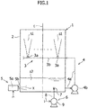
Fig. 1] Fig. 1 is a front view schematically showing a wet type exhaust gas desulfurization apparatus according to a preferred embodiment of the present invention. - [
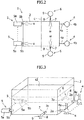
Fig. 2] Fig. 2 is a cross section view schematically showing a bottom and peripheral portions of an absorption tower according to a preferred embodiment of the present invention. - [
Fig. 3] Fig. 3 is a perspective view that briefly shows the bottom and peripheral portions of an absorption tower according to a preferred embodiment of the present invention. - A wet type exhaust gas desulfurization apparatus (hereinafter simply referred to as a "desulfurization apparatus") according to a preferred embodiment of the present invention will be described below with reference to the attached drawings.
- Referring to
Figs. 1 and2 , adesulfurization apparatus 1 includes anabsorption tower 2, and theabsorption tower 2 is hollow and has a substantially box-like shape. Although not described in the drawings, exhaust gas containing sulfur oxides (SOx), such as sulfur dioxide (SO2), is fed into theabsorption tower 2. Furthermore, after being fed into theabsorption tower 2, the exhaust gas is desulfurized by using an absorbent, and then the desulfurized exhaust gas is discharged to the outside of theabsorption tower 2. Note that thedesulfurization apparatus 1 according to the present preferred embodiment of the present invention employs the limestone gypsum method. In the present preferred embodiment, limestone slurry that uses limestone (calcium carbonate (CaCO3)) is used as the absorbent. - Referring to
Fig. 1 , thedesulfurization apparatus 1 includes aspray mechanism 3, and thespray mechanism 3 is configured to spray the absorbent into theabsorption tower 2. Thespray mechanism 3 includesmultiple spray nozzles 3a. To thespray nozzles 3a, aheader tube 3b is connected. With this configuration, absorbent s1 is fed from theheader tube 3b into thespray nozzles 3a. After being sprayed into theabsorption tower 2, the absorbent s1 accumulates on the bottom portion of the absorption tower 2 (refer toFig. 1 for accumulated absorbent s2). As shown inFigs. 1 to 3 , in order to use the absorbent s2 which is accumulated in the above-described manner in desulfurizing exhaust gas inside theabsorption tower 2, thedesulfurization apparatus 1 includesmultiple circulation mechanisms 4, and themultiple circulation mechanisms 4 are configured to feed the absorbent s2 which is accumulated in the bottom portion of theabsorption tower 2, from adischarge port 2a (Fig. 3 ) which is provided to theabsorption tower 2 on the bottom portion thereof, to theheader tube 3b which is positioned on an upstream of thespray nozzles 3a in the direction of the flow of the absorbent (hereinafter simply referred to as "upstream (side)" (of thespray nozzles 3a in the flow of the absorbent). In addition, thedesulfurization apparatus 1 includesmultiple oxidization mechanisms 5, and themultiple oxidization mechanisms 5 are configured to supply oxygen to the absorbent s2 accumulated inside the absorption tower 2 (refer toFigs. 1 and2 for supplied oxygen x). In addition, thedesulfurization apparatus 1 includes a pair ofliquid ejection mechanisms 6, and the pair of theliquid ejection mechanism 6 is configured to eject liquid onto the absorbent s2 which has accumulated inside the absorption tower 2 (refer toFigs. 1 and2 for ejected water w). More specifically, the liquid ejected by theliquid ejection mechanism 6 is water. Note here that thespray mechanism 3, thecirculation mechanism 4, and theoxidization mechanism 5 are configured to be started and stopped in interlock with one another. On the other hand, theliquid ejection mechanism 6 can be started and stopped separately and independently from thespray mechanism 3, thecirculation mechanism 4, and theoxidization mechanism 5. - Now, the
spray mechanism 3 and thecirculation mechanism 4 will be described in detail below with reference toFigs. 1 to 3 . Referring toFig. 1 , each of themultiple spray nozzles 3a in thespray mechanism 3 are arranged apart from one another in the direction of the flow of the absorbent flowing in theheader tube 3b. As to the direction of spraying the absorbent from thespray nozzles 3a, thespray nozzles 3a spray the absorbent upwards in thedesulfurization apparatus 1. Theheader tube 3b is formed to extend in the horizontal direction of thedesulfurization apparatus 1. Referring toFigs. 1 to 3 , thedesulfurization apparatus 1 includes acirculation tube 4a. Thecirculation tube 4a connects theabsorption tower 2 and theheader tube 3b in the bottom portion of theabsorption tower 2 and on an upstream end of theheader tube 3b. To thecirculation tube 4a, acirculation pump 4b is installed. The absorbent s2 which has accumulated in the bottom portion of theabsorption tower 2, is lifted by thecirculation pump 4b and then is fed from thedischarge port 2a of the absorption tower 2 (refer toFig. 3 ) to the upstream edge of theheader tube 3b through thecirculation tube 4a. - Now, the
oxidization mechanism 5 will be described in detail below with reference toFigs. 1 to 3 . Theoxidization mechanism 5 is installed to theabsorption tower 2 on the side surface of theabsorption tower 2 in the bottom portion thereof. Theoxidization mechanism 5 is provided with a gap from thedischarge port 2a of theabsorption tower 2 in the horizontal direction and is provided at an opposing location against thedischarge port 2a. Theoxidization mechanism 5 includes anoxygen supply tube 5b, and theoxygen supply tube 5b extends from an oxidization mechanismmain body 5a towards the inside of theabsorption tower 2. The oxygen x is supplied from the oxidization mechanismmain body 5a of theoxidization mechanism 5 to the absorbent s2 which has accumulated inside theabsorption tower 2, via theoxygen supply tube 5b. - The
liquid ejection mechanism 6 will be described in detail below with reference toFigs. 1 to 3 . Theliquid ejection mechanism 6 includes ahydraulic nozzle 7, and thehydraulic nozzle 7 is configured to eject water w into theabsorption tower 2. Referring toFig. 3 , thehydraulic nozzle 7 includes aliquid ejection port 7a, and theliquid ejection port 7a has a substantially circular shape. Water supplied to thehydraulic nozzle 7 is fed into theabsorption tower 2 via theliquid ejection port 7a. A pair of thehydraulic nozzles 7 is installed to theabsorption tower 2 on the mutually opposing side surfaces in the bottom portion of theabsorption tower 2. Theliquid ejection ports 7a of the pair of thehydraulic nozzles 7 are provided at mutually opposing locations. In addition, the pair of thehydraulic nozzle 7 is arranged at a location closer to thedischarge port 2a from a center C (Fig. 2 ), in a horizontal direction, between a group ofdischarge ports 2a of theabsorption tower 2 and a group of theoxidization mechanisms 5. Furthermore, theliquid ejection mechanism 6 includes aliquid supply tube 8, and theliquid supply tube 8 is configured to feed water to thehydraulic nozzle 7 from outside theabsorption tower 2. Aliquid supply pump 9 is provided to theliquid supply tube 8. After being lifted by theliquid supply pump 9 with a predetermined pressure, the water is fed to thehydraulic nozzle 7 via theliquid supply tube 8 from outside theabsorption tower 2 with the pressure that is applied by the lifting by theliquid supply pump 9, being maintained. - Now, a method for using the
desulfurization apparatus 1 according to the present preferred embodiment of the present invention will be described in detail below. - At the start up of the operation, the absorbent s2 that has accumulated in the bottom portion of the
absorption tower 2, is lifted by thepump 4b of thecirculation mechanism 4. Accordingly, the absorbent s2 is then fed to the upstream side edge of theheader tube 3b of thespray mechanism 3 via thecirculation tube 4a. The absorbent fed to theheader tube 3b is then fed to thespray nozzle 3a, and thespray nozzle 3a sprays the absorbent inside theabsorption tower 2. The sprayed absorbent s1 reacts with the exhaust gas that has been fed into theabsorption tower 2, and the sprayed absorbent s1 absorbs sulfur oxides contained in the exhaust gas. Subsequently, the sprayed absorbent s1 falls and accumulates on the bottom portion of theabsorption tower 2. The absorbent s2 that has accumulated in the bottom portion of theabsorption tower 2, is lifted by thepump 4b of thecirculation mechanism 4, and is then fed to the upstream side edge of theheader tube 3b via thecirculation tube 4a again so as to be used in the desulfurization of the exhaust gas. More specifically, the absorbent can circulate through a path through which the absorbent is fed in the order of theabsorption tower 2, thecirculation tube 4a, theheader tube 3b, thespray nozzles 3a, and theabsorption tower 2. In theoxidization mechanism 5, oxygen x is supplied from the oxygen supply tube (port) 5b to the absorbent s2 which has accumulated in the bottom portion of theabsorption tower 2, so as to oxidize the absorbent s2 which has accumulated in the bottom portion of theabsorption tower 2. - Now, a method for agitating the absorbent s2 which has accumulated inside the
absorption tower 2 of thedesulfurization apparatus 1 according to the present preferred embodiment will be described in detail below. - At the start up of the operation, the
liquid ejection mechanism 6 is started, and then the liquid supply pump 9 lifts water from outside theabsorption tower 2 with a predetermined pressure. After being lifted by theliquid supply pump 9, the water is fed from outside theabsorption tower 2 to thehydraulic nozzle 7 via theliquid supply tube 8 with the pressure that is applied by the lifting by theliquid supply pump 9, being maintained. After being fed to thehydraulic nozzle 7, the water w is ejected onto the absorbent s2 that has accumulated inside theabsorption tower 2, via the fluid supply (ejection)port 7a of thehydraulic nozzle 7. The water w that is ejected from thehydraulic nozzle 7 causes the absorbent s2 that has accumulated inside theabsorption tower 2, to flow in a vortex. When the absorbent s2 which has accumulated inside theabsorption tower 2, flows in a vortex, the absorbent s2 that has accumulated inside theabsorption tower 2, is agitated. Accordingly, if a sorbent suspended within the absorbent s2 that has accumulated inside theabsorption tower 2 settles (this phenomenon will hereinafter be referred to as "slurry precipitation"), the vortex flow of the absorbent causes the settled sorbent to be crushed into fine particles mainly in a portion between thedischarge port 2a of theabsorption tower 2 and theoxidization mechanism 5. - As described above, in the
desulfurization apparatus 1 according to the present invention, the water w which is ejected from thehydraulic nozzle 7, causes the absorbent s2 which has accumulated inside theabsorption tower 2, to flow in a vortex. When the absorbent s2 which has accumulated inside theabsorption tower 2, flows in a vortex, the absorbent s2 that has accumulated inside theabsorption tower 2, is agitated. Therefore, if the phenomenon of slurry precipitation occurs, the vortex flow of the water w which is ejected from thehydraulic nozzle 7, causes the settled sorbent to be crushed into fine particles mainly in a portion between thedischarge port 2a of theabsorption tower 2 and theoxidization mechanism 5. Accordingly, the absorbent is well agitated between thedischarge port 2a of theabsorption tower 2 and theoxidization mechanism 5 in particular. As a result, at the same time when thecirculation mechanism 4 is started, the oxygen fed from theoxidization mechanism 5 is further fed to the absorbent that has been efficiently agitated between thedischarge port 2a of theabsorption tower 2 and theoxidization mechanism 5. Accordingly, the absorbent that has accumulated inside theabsorption tower 2, can be immediately oxidized. Subsequently, the absorbent that has been efficiently agitated and oxidized, is fed to thedischarge port 2a of theabsorption tower 2, and circulates within thedesulfurization apparatus 1. Accordingly, thedesulfurization apparatus 1 can be stably operated. - The present preferred embodiment has a simple configuration of ejecting the water w from the
hydraulic nozzle 7 into the absorbent as the configuration of the method for agitating the absorbent. Accordingly, the configuration of the mechanism for agitating the absorbent can be simplified. In addition, the mechanism for agitating the absorbent does not occupy the inner space of theabsorption tower 2. Accordingly, a large space can be secured inside theabsorption tower 2. As a result, a maintenance operation of the inside of theabsorption tower 2 can be easily executed. Accordingly, the maintenance operation of thedesulfurization apparatus 1 can be easily carried out. Furthermore, the size of thedesulfurization apparatus 1 can be small. - The specific gravity of the water w ejected from the
hydraulic nozzle 7 is higher than the specific gravity of air used in the conventional method. Accordingly, the water w ejected from thehydraulic nozzle 7 can be easily supplied into the absorbent in the horizontal direction. Therefore, the water w can be ejected from thehydraulic nozzle 7 with a pressure lower than the pressure applied to air in the conventional method. In addition, the present preferred embodiment can agitate the absorbent sufficiently well by the effect of the vortex flow of the absorbent. - In the
desulfurization apparatus 1 according to the present preferred embodiment of the present invention, thehydraulic nozzle 7 is provided at a location closer to thedischarge port 2a from a center C (Fig. 2 ), in a horizontal direction, between thedischarge port 2a of theabsorption tower 2 and theoxidization mechanism 5. Therefore, the settled sorbent can be efficiently crushed into fine particles around thedischarge port 2a of theabsorption tower 2, thedischarge port 2a of theabsorption tower 2 being the path for circulating the absorbent. Accordingly, otherwise possible clogging of the settled sorbent over the path for the absorbent can be prevented. As a result, thedesulfurization apparatus 1 can be stably operated. - In the
desulfurization apparatus 1 according to the present preferred embodiment of the present invention, theliquid ejection mechanism 6 is configured to supply the water lifted from outside theabsorption tower 2 to thehydraulic nozzle 7 in a condition in which the pressure applied by the lifting is maintained. Accordingly, the mechanism for feeding water to thehydraulic nozzle 7, such as theliquid supply tube 8 or theliquid supply pump 9, can be simplified. Therefore, the configuration of the mechanism for agitating the absorbent can be simplified. - In addition, in the
desulfurization apparatus 1 according to the present preferred embodiment of the present invention, theliquid ejection mechanism 6 can be started and stopped separately and independently from thespray mechanism 3, thecirculation mechanism 4, and theoxidization mechanism 5. Therefore, for example, theliquid ejection mechanism 6 is started and is operated before starting thespray mechanism 3, thecirculation mechanism 4, and theoxidization mechanism 5, which are main component mechanisms of thedesulfurization apparatus 1, so that thedesulfurization apparatus 1 can be stably operated immediately after thespray mechanism 3, thecirculation mechanism 4, and theoxidization mechanism 5 are started by suppressing the phenomenon of the slurry precipitation. - The present preferred embodiment of the present invention is described above. However, the present invention is not limited to the above-described preferred embodiment. More specifically, various modifications and alterations can implement the present invention on the basis of the technical ideas of the present invention.
- For example, as a first modification of the present invention, slurry that uses slaked lime (calcium hydroxide (Ca(OH)2)) or dolomite as the sorbent can be used as the absorbent. The
desulfurization apparatus 1 can employ the magnesium hydroxide method. In this case, it is useful to use, as the absorbent, slurry that uses magnesium hydroxide or the like as the sorbent. Thedesulfurization apparatus 1 can employ the sodium hydroxide method. In this case, it is useful to use, as the absorbent, slurry that uses sodium hydroxide, sodium sulfate, or the like as the sorbent. Thedesulfurization apparatus 1 can employ the ammonia absorption method. In this case, it is useful to use, as the absorbent, slurry that uses ammonia or the like as the sorbent. - As a second modification of the present invention, the
spray nozzles 3a can spray the absorbent downwards, in the horizontal direction, or in a slanting direction. - As a third modification of the present invention, the
header tube 3b can include a bent portion, a warped portion, a portion extending in the vertical direction, or an inclined portion. - As a fourth modification of the present invention, the
absorption tower 2 can have a substantially cylinder-like shape, a substantially cone-like shape, a substantially cylindroid-like shape, a substantially elliptic cone-like shape, or a substantially polygonal pyramid-like shape. - As a fifth modification of the present invention, liquid other than water can be ejected from the
hydraulic nozzle 7. More specifically, thehydraulic nozzle 7 can eject liquid of the same type as the absorbent, or liquid of the same type as the liquid before the sorbent is suspended in the absorbent. - As a sixth modification of the present invention, one or more
liquid ejection mechanisms 6 can be installed to theabsorption tower 2 on one of the mutually opposing sides of theabsorption tower 2 in the bottom portion of theabsorption tower 2. - As a seventh modification of the present invention, multiple pairs of the
liquid ejection mechanisms 6 can be provided. - As an eighth modification of the present invention, the
liquid ejection port 7a of thehydraulic nozzle 7 can have a substantially semicircular shape, a substantially ellipse-like shape, a substantially semiellipse-like shape, a substantially polygonal shape, or a substantially star-like shape. - As a ninth modification of the present invention, the
liquid ejection ports 7a of the pair of thehydraulic nozzle 7 can be provided with an offset in the vertical, horizontal, and/or the peripheral direction of theabsorption tower 2. - As a tenth modification of the present invention, liquid can naturally fall from the
liquid ejection mechanism 6 at liquid supply positions which are set with intervals taken in the vertical direction of theabsorption tower 2, onto the liquid level of the absorbent s2 which has accumulated in the bottom portion of theabsorption tower 2, so that the absorbent s2 which has accumulated in the bottom portion of theabsorption tower 2, can be agitated. More specifically, it is useful to set the liquid supply positions being set with sufficient intervals in the vertical direction of theabsorption tower 2 relative to the liquid level of the absorbent s2 which has accumulated in the bottom portion of theabsorption tower 2 in order to efficiently agitate the absorbent s2 which has accumulated in the bottom portion of theabsorption tower 2. -
- 1
- Wet type exhaust gas desulfurization apparatus (Desulfurization apparatus)
- 2
- Absorption tower
- 2a
- Discharge port
- 3
-
Spray mechanism 3 - 4
- Circulation mechanism
- 5
- Oxidization mechanism
- 6
- Liquid ejection mechanisms
- 7
- Hydraulic nozzle
- s1, s2
- Absorbent
- w
- Water
- x
- Oxygen
- C
- Center in horizontal direction
Claims (4)
- A wet type exhaust gas desulfurization apparatus comprising:an absorption tower (2) configured to desulfurize exhaust gas by causing the exhaust gas to come into gas-liquid contact with an absorbent (s1);a spray mechanism (3) configured to spray the absorbent (s1) into the absorption tower (2);an oxidization mechanism (5) having an oxidization mechanism main body (5a) that includes an oxygen supply tube (5b) and which is attached on the side surface of the absorption tower (2) to the bottom portion of the absorption tower (2), the oxidization mechanism (5) being configured to supply oxygen from the oxidization mechanism main body to absorbent accumulating inside the absorption tower via the oxygen supply tube (5b);a circulation mechanism (4) configured to feed the absorbent from a discharge port (2a), which is formed in the bottom portion of the absorption tower (2), to the spray mechanism (3); anda pair of liquid ejection mechanisms (6) including a pair of hydraulic nozzles (7) configured to eject liquid into the absorption tower (2) respectively;
characterized in that multiple oxidization mechanisms (5) are arranged apart from one another in a horizontal direction relative to the discharge port (2a) of the absorption tower such that there is a gap from the discharge port (2a) of the absorption tower (2) in the horizontal direction and the oxidation mechanism is provided at an opposing location against the discharge port (2a); andwherein the pair of the hydraulic nozzles (7) is installed to mutually opposing side surfaces in the bottom portion of the absorption tower (2) respectively such that liquid ejection ports of the pair of the hydraulic nozzles (7) are provided at mutually opposing locations between the oxidization mechanism (5) and the discharge port (2a) of the absorption tower. - The wet type exhaust gas desulfurization apparatus according to claim 1, wherein
the pair of hydraulic nozzles (7) is arranged at a location closer to the discharge port (2a) relative to a center, in a horizontal direction, between the oxidization mechanism and the discharge port of the absorption tower. - The wet type exhaust gas desulfurization apparatus according to claim 1, wherein
the liquid ejection mechanism (6) includes a liquid supply tube configured to feed liquid to the hydraulic nozzle, and a liquid supply pump attached to the liquid supply tube, and
the liquid ejection mechanism is configured such that the liquid lifted by the liquid supply pump, is fed to the hydraulic nozzle via the liquid supply tube from outside the absorption tower, and such that the pressure applied to the liquid by the lifting by the liquid supply pump is maintained. - The wet type exhaust gas desulfurization apparatus according to claim 3, wherein
the liquid ejection mechanism (6) is configured to be capable of being started and stopped separately and independently from the spray mechanism (3), the oxidization mechanism, and the circulation mechanism (4).
Priority Applications (1)
| Application Number | Priority Date | Filing Date | Title |
|---|---|---|---|
| PL13825594T PL2881161T3 (en) | 2012-07-30 | 2013-07-10 | Wet type exhaust gas desulfurization apparatus |
Applications Claiming Priority (2)
| Application Number | Priority Date | Filing Date | Title |
|---|---|---|---|
| US13/561,386 US9028762B2 (en) | 2012-07-30 | 2012-07-30 | Wet type exhaust gas desulfurization apparatus |
| PCT/JP2013/068845 WO2014021068A1 (en) | 2012-07-30 | 2013-07-10 | Wet flue gas desulfurization equipment |
Publications (3)
| Publication Number | Publication Date |
|---|---|
| EP2881161A1 EP2881161A1 (en) | 2015-06-10 |
| EP2881161A4 EP2881161A4 (en) | 2015-08-12 |
| EP2881161B1 true EP2881161B1 (en) | 2018-06-20 |
Family
ID=49995085
Family Applications (1)
| Application Number | Title | Priority Date | Filing Date |
|---|---|---|---|
| EP13825594.8A Not-in-force EP2881161B1 (en) | 2012-07-30 | 2013-07-10 | Wet type exhaust gas desulfurization apparatus |
Country Status (9)
| Country | Link |
|---|---|
| US (1) | US9028762B2 (en) |
| EP (1) | EP2881161B1 (en) |
| JP (1) | JP6227531B2 (en) |
| KR (1) | KR101797327B1 (en) |
| CN (1) | CN104602787B (en) |
| ES (1) | ES2674920T3 (en) |
| IN (1) | IN2015DN00174A (en) |
| PL (1) | PL2881161T3 (en) |
| WO (1) | WO2014021068A1 (en) |
Families Citing this family (6)
| Publication number | Priority date | Publication date | Assignee | Title |
|---|---|---|---|---|
| CN107213761A (en) * | 2017-06-30 | 2017-09-29 | 成都川通达科技有限公司 | A kind of Novel desulfurization tower |
| CN108187473A (en) * | 2018-02-05 | 2018-06-22 | 郑兴华 | A kind of recycling desulphurization system |
| CN108525496B (en) * | 2018-04-26 | 2020-12-15 | 江苏蓝电环保股份有限公司 | Sulfide purification treatment method for industrial waste gas |
| JP6588147B1 (en) * | 2018-12-11 | 2019-10-09 | 三菱日立パワーシステムズ株式会社 | Exhaust gas desulfurization equipment |
| CN109395543A (en) * | 2018-12-31 | 2019-03-01 | 广东威特宝土壤修复科研中心有限公司 | Soaking type exhaust gas separating treatment system and method |
| CN110237670B (en) * | 2019-06-27 | 2021-06-18 | 成都海成环保工程有限公司 | Circulating desulfurization system adopting double-alkali method and desulfurization process thereof |
Family Cites Families (21)
| Publication number | Priority date | Publication date | Assignee | Title |
|---|---|---|---|---|
| JPS58104619A (en) * | 1981-12-15 | 1983-06-22 | Ishikawajima Harima Heavy Ind Co Ltd | Absorption tower of flue gas desulfurization equipment |
| DE3227187C1 (en) * | 1982-07-21 | 1988-12-01 | Gottfried Bischoff Bau kompl. Gasreinigungs- und Wasserrückkühlanlagen GmbH & Co KG, 4300 Essen | Wash tower for a plant for the desulphurization of flue gas |
| JPH0773657B2 (en) * | 1986-08-07 | 1995-08-09 | 三菱重工業株式会社 | Wet Flue Gas Desulfurization Method |
| JPH0555176A (en) | 1991-08-26 | 1993-03-05 | Sony Corp | Dry etching method |
| JPH07108131A (en) | 1993-10-08 | 1995-04-25 | Mitsubishi Heavy Ind Ltd | Treatment of waste gas |
| DE4338332A1 (en) * | 1993-11-10 | 1995-05-11 | Bischoff Gasreinigung | Wash tower for a flue gas desulfurization plant |
| JP2989484B2 (en) * | 1994-08-18 | 1999-12-13 | 三菱重工業株式会社 | Wet flue gas desulfurization equipment |
| JP3170158B2 (en) | 1994-11-08 | 2001-05-28 | 三菱重工業株式会社 | Gas-liquid contact device and wet flue gas desulfurization device |
| US5676716A (en) * | 1995-10-30 | 1997-10-14 | The Babcock & Wilcox Company | Apparatus for mixing a tank and improving air/liquid contact in an oxidized system |
| JP3337380B2 (en) | 1996-10-17 | 2002-10-21 | 三菱重工業株式会社 | Exhaust gas treatment method |
| JP3676020B2 (en) * | 1997-02-26 | 2005-07-27 | バブコック日立株式会社 | Wet flue gas desulfurization equipment |
| DE69716942D1 (en) * | 1997-10-07 | 2002-12-12 | Nippon Kokan Kk | METHOD FOR THE WET DESULFURATION OF EXHAUST GAS |
| DE69921605T2 (en) | 1998-08-11 | 2005-08-04 | Mitsubishi Heavy Industries, Ltd. | DEVICE FOR WET PURIFICATION OF EXHAUST GASES |
| JP3854481B2 (en) | 2000-11-17 | 2006-12-06 | 三菱重工業株式会社 | Wet flue gas desulfurization apparatus and wet flue gas desulfurization method |
| JP2002361035A (en) | 2001-06-06 | 2002-12-17 | Babcock Hitachi Kk | Boiler flue gas treatment equipment |
| JP2003170039A (en) * | 2001-12-10 | 2003-06-17 | Ishikawajima Harima Heavy Ind Co Ltd | Reactor |
| JP4734537B2 (en) * | 2005-05-24 | 2011-07-27 | 川崎重工業株式会社 | Absorption tower of flue gas desulfurization equipment |
| JP5046755B2 (en) * | 2007-06-27 | 2012-10-10 | 三菱重工業株式会社 | Gas-liquid contact device |
| CN101185839B (en) * | 2007-09-10 | 2010-09-01 | 中电投远达环保工程有限公司 | Wet flue gas desulfurization jet oxidation system |
| JP2011005448A (en) * | 2009-06-26 | 2011-01-13 | Mitsubishi Heavy Ind Ltd | River water utilization flue gas desulfurizing system and method of removing humus |
| CN101844036A (en) * | 2010-05-11 | 2010-09-29 | 上海龙净环保科技工程有限公司 | Wet flue gas desulfurization (WFGD) process for gypsum through oxidization in tower by using calcium-based strongly basic substance |
-
2012
- 2012-07-30 US US13/561,386 patent/US9028762B2/en not_active Expired - Fee Related
-
2013
- 2013-07-10 CN CN201380040179.7A patent/CN104602787B/en not_active Expired - Fee Related
- 2013-07-10 JP JP2014528055A patent/JP6227531B2/en not_active Expired - Fee Related
- 2013-07-10 PL PL13825594T patent/PL2881161T3/en unknown
- 2013-07-10 KR KR1020157002036A patent/KR101797327B1/en not_active Expired - Fee Related
- 2013-07-10 WO PCT/JP2013/068845 patent/WO2014021068A1/en not_active Ceased
- 2013-07-10 ES ES13825594.8T patent/ES2674920T3/en active Active
- 2013-07-10 EP EP13825594.8A patent/EP2881161B1/en not_active Not-in-force
-
2015
- 2015-01-08 IN IN174DEN2015 patent/IN2015DN00174A/en unknown
Non-Patent Citations (1)
| Title |
|---|
| None * |
Also Published As
| Publication number | Publication date |
|---|---|
| JP6227531B2 (en) | 2017-11-08 |
| IN2015DN00174A (en) | 2015-06-12 |
| US20140030157A1 (en) | 2014-01-30 |
| CN104602787A (en) | 2015-05-06 |
| CN104602787B (en) | 2017-07-04 |
| WO2014021068A1 (en) | 2014-02-06 |
| ES2674920T3 (en) | 2018-07-05 |
| EP2881161A1 (en) | 2015-06-10 |
| KR20150024924A (en) | 2015-03-09 |
| EP2881161A4 (en) | 2015-08-12 |
| US9028762B2 (en) | 2015-05-12 |
| KR101797327B1 (en) | 2017-11-13 |
| JPWO2014021068A1 (en) | 2016-07-21 |
| PL2881161T3 (en) | 2018-10-31 |
Similar Documents
| Publication | Publication Date | Title |
|---|---|---|
| EP2881161B1 (en) | Wet type exhaust gas desulfurization apparatus | |
| JP5668244B2 (en) | Flue gas desulfurization apparatus, combustion system, and combustion method | |
| JP6730024B2 (en) | Liquid screen dust remover and flue gas desulfurizer | |
| EP1958682B1 (en) | Wet flue-gas desulfurization apparatus and method of wet flue-gas desulfurization | |
| TW402520B (en) | Wet flue gas desulfurizer and oxygen-containing gas blowing device for use therein | |
| CN105169926A (en) | Flue gas desulphurization system and method for flue gas desulfurization by means of same | |
| JP3564289B2 (en) | Method and apparatus for treating desulfurization absorbent | |
| KR101782786B1 (en) | A wet desulfurization unit | |
| KR0179220B1 (en) | Wet flue gas desulfurization device | |
| JP2000210532A (en) | Flue gas desulfurization equipment | |
| JP5770421B2 (en) | Exhaust gas treatment equipment | |
| US9056273B2 (en) | Wet type exhaust gas desulfurization apparatus | |
| WO2014196458A1 (en) | Device for desulfurization with seawater and system for desulfurization with seawater | |
| JP4734537B2 (en) | Absorption tower of flue gas desulfurization equipment | |
| JP3842706B2 (en) | Wet flue gas desulfurization apparatus and method | |
| JP4933121B2 (en) | Combustion exhaust gas purifier with separated cleaning liquid reservoir | |
| JPH09206549A (en) | Wet stack gas desulfurizer | |
| JPH0910546A (en) | Wet type flue gas desulfurization device | |
| JP2005193133A (en) | Gas treatment column | |
| JP3061750B2 (en) | Exhaust gas wet treatment equipment | |
| JPH08103626A (en) | Exhaust gas desulfurization method | |
| JP2000176321A (en) | Spray equipment | |
| JPS62183841A (en) | Wet flue gas desulfurizing apparatus | |
| JP2002113324A (en) | Wet lime gypsum method desulfurization method and apparatus | |
| JP2011194296A (en) | Flue gas desulfurization equipment |
Legal Events
| Date | Code | Title | Description |
|---|---|---|---|
| PUAI | Public reference made under article 153(3) epc to a published international application that has entered the european phase |
Free format text: ORIGINAL CODE: 0009012 |
|
| 17P | Request for examination filed |
Effective date: 20150129 |
|
| AK | Designated contracting states |
Kind code of ref document: A1 Designated state(s): AL AT BE BG CH CY CZ DE DK EE ES FI FR GB GR HR HU IE IS IT LI LT LU LV MC MK MT NL NO PL PT RO RS SE SI SK SM TR |
|
| AX | Request for extension of the european patent |
Extension state: BA ME |
|
| RA4 | Supplementary search report drawn up and despatched (corrected) |
Effective date: 20150713 |
|
| RIC1 | Information provided on ipc code assigned before grant |
Ipc: B01D 53/77 20060101ALI20150707BHEP Ipc: C02F 103/18 20060101ALI20150707BHEP Ipc: B01D 53/18 20060101ALI20150707BHEP Ipc: B01D 53/50 20060101AFI20150707BHEP Ipc: C02F 1/72 20060101ALI20150707BHEP |
|
| DAX | Request for extension of the european patent (deleted) | ||
| 17Q | First examination report despatched |
Effective date: 20171024 |
|
| GRAP | Despatch of communication of intention to grant a patent |
Free format text: ORIGINAL CODE: EPIDOSNIGR1 |
|
| INTG | Intention to grant announced |
Effective date: 20180105 |
|
| GRAS | Grant fee paid |
Free format text: ORIGINAL CODE: EPIDOSNIGR3 |
|
| GRAA | (expected) grant |
Free format text: ORIGINAL CODE: 0009210 |
|
| AK | Designated contracting states |
Kind code of ref document: B1 Designated state(s): AL AT BE BG CH CY CZ DE DK EE ES FI FR GB GR HR HU IE IS IT LI LT LU LV MC MK MT NL NO PL PT RO RS SE SI SK SM TR |
|
| REG | Reference to a national code |
Ref country code: GB Ref legal event code: FG4D |
|
| REG | Reference to a national code |
Ref country code: ES Ref legal event code: FG2A Ref document number: 2674920 Country of ref document: ES Kind code of ref document: T3 Effective date: 20180705 |
|
| REG | Reference to a national code |
Ref country code: IE Ref legal event code: FG4D |
|
| REG | Reference to a national code |
Ref country code: AT Ref legal event code: REF Ref document number: 1010171 Country of ref document: AT Kind code of ref document: T Effective date: 20180715 |
|
| REG | Reference to a national code |
Ref country code: DE Ref legal event code: R096 Ref document number: 602013039229 Country of ref document: DE |
|
| REG | Reference to a national code |
Ref country code: NL Ref legal event code: MP Effective date: 20180620 |
|
| PG25 | Lapsed in a contracting state [announced via postgrant information from national office to epo] |
Ref country code: SE Free format text: LAPSE BECAUSE OF FAILURE TO SUBMIT A TRANSLATION OF THE DESCRIPTION OR TO PAY THE FEE WITHIN THE PRESCRIBED TIME-LIMIT Effective date: 20180620 Ref country code: BG Free format text: LAPSE BECAUSE OF FAILURE TO SUBMIT A TRANSLATION OF THE DESCRIPTION OR TO PAY THE FEE WITHIN THE PRESCRIBED TIME-LIMIT Effective date: 20180920 Ref country code: NO Free format text: LAPSE BECAUSE OF FAILURE TO SUBMIT A TRANSLATION OF THE DESCRIPTION OR TO PAY THE FEE WITHIN THE PRESCRIBED TIME-LIMIT Effective date: 20180920 Ref country code: FI Free format text: LAPSE BECAUSE OF FAILURE TO SUBMIT A TRANSLATION OF THE DESCRIPTION OR TO PAY THE FEE WITHIN THE PRESCRIBED TIME-LIMIT Effective date: 20180620 Ref country code: LT Free format text: LAPSE BECAUSE OF FAILURE TO SUBMIT A TRANSLATION OF THE DESCRIPTION OR TO PAY THE FEE WITHIN THE PRESCRIBED TIME-LIMIT Effective date: 20180620 |
|
| REG | Reference to a national code |
Ref country code: LT Ref legal event code: MG4D |
|
| PG25 | Lapsed in a contracting state [announced via postgrant information from national office to epo] |
Ref country code: HR Free format text: LAPSE BECAUSE OF FAILURE TO SUBMIT A TRANSLATION OF THE DESCRIPTION OR TO PAY THE FEE WITHIN THE PRESCRIBED TIME-LIMIT Effective date: 20180620 Ref country code: RS Free format text: LAPSE BECAUSE OF FAILURE TO SUBMIT A TRANSLATION OF THE DESCRIPTION OR TO PAY THE FEE WITHIN THE PRESCRIBED TIME-LIMIT Effective date: 20180620 Ref country code: GR Free format text: LAPSE BECAUSE OF FAILURE TO SUBMIT A TRANSLATION OF THE DESCRIPTION OR TO PAY THE FEE WITHIN THE PRESCRIBED TIME-LIMIT Effective date: 20180921 Ref country code: LV Free format text: LAPSE BECAUSE OF FAILURE TO SUBMIT A TRANSLATION OF THE DESCRIPTION OR TO PAY THE FEE WITHIN THE PRESCRIBED TIME-LIMIT Effective date: 20180620 |
|
| REG | Reference to a national code |
Ref country code: AT Ref legal event code: MK05 Ref document number: 1010171 Country of ref document: AT Kind code of ref document: T Effective date: 20180620 |
|
| PG25 | Lapsed in a contracting state [announced via postgrant information from national office to epo] |
Ref country code: NL Free format text: LAPSE BECAUSE OF FAILURE TO SUBMIT A TRANSLATION OF THE DESCRIPTION OR TO PAY THE FEE WITHIN THE PRESCRIBED TIME-LIMIT Effective date: 20180620 |
|
| PG25 | Lapsed in a contracting state [announced via postgrant information from national office to epo] |
Ref country code: IS Free format text: LAPSE BECAUSE OF FAILURE TO SUBMIT A TRANSLATION OF THE DESCRIPTION OR TO PAY THE FEE WITHIN THE PRESCRIBED TIME-LIMIT Effective date: 20181020 Ref country code: CZ Free format text: LAPSE BECAUSE OF FAILURE TO SUBMIT A TRANSLATION OF THE DESCRIPTION OR TO PAY THE FEE WITHIN THE PRESCRIBED TIME-LIMIT Effective date: 20180620 Ref country code: RO Free format text: LAPSE BECAUSE OF FAILURE TO SUBMIT A TRANSLATION OF THE DESCRIPTION OR TO PAY THE FEE WITHIN THE PRESCRIBED TIME-LIMIT Effective date: 20180620 Ref country code: AT Free format text: LAPSE BECAUSE OF FAILURE TO SUBMIT A TRANSLATION OF THE DESCRIPTION OR TO PAY THE FEE WITHIN THE PRESCRIBED TIME-LIMIT Effective date: 20180620 Ref country code: EE Free format text: LAPSE BECAUSE OF FAILURE TO SUBMIT A TRANSLATION OF THE DESCRIPTION OR TO PAY THE FEE WITHIN THE PRESCRIBED TIME-LIMIT Effective date: 20180620 Ref country code: SK Free format text: LAPSE BECAUSE OF FAILURE TO SUBMIT A TRANSLATION OF THE DESCRIPTION OR TO PAY THE FEE WITHIN THE PRESCRIBED TIME-LIMIT Effective date: 20180620 |
|
| REG | Reference to a national code |
Ref country code: DE Ref legal event code: R119 Ref document number: 602013039229 Country of ref document: DE |
|
| PG25 | Lapsed in a contracting state [announced via postgrant information from national office to epo] |
Ref country code: SM Free format text: LAPSE BECAUSE OF FAILURE TO SUBMIT A TRANSLATION OF THE DESCRIPTION OR TO PAY THE FEE WITHIN THE PRESCRIBED TIME-LIMIT Effective date: 20180620 |
|
| REG | Reference to a national code |
Ref country code: CH Ref legal event code: PL |
|
| PG25 | Lapsed in a contracting state [announced via postgrant information from national office to epo] |
Ref country code: MC Free format text: LAPSE BECAUSE OF FAILURE TO SUBMIT A TRANSLATION OF THE DESCRIPTION OR TO PAY THE FEE WITHIN THE PRESCRIBED TIME-LIMIT Effective date: 20180620 Ref country code: LU Free format text: LAPSE BECAUSE OF NON-PAYMENT OF DUE FEES Effective date: 20180710 |
|
| REG | Reference to a national code |
Ref country code: BE Ref legal event code: MM Effective date: 20180731 |
|
| REG | Reference to a national code |
Ref country code: IE Ref legal event code: MM4A |
|
| PLBE | No opposition filed within time limit |
Free format text: ORIGINAL CODE: 0009261 |
|
| STAA | Information on the status of an ep patent application or granted ep patent |
Free format text: STATUS: NO OPPOSITION FILED WITHIN TIME LIMIT |
|
| PG25 | Lapsed in a contracting state [announced via postgrant information from national office to epo] |
Ref country code: CH Free format text: LAPSE BECAUSE OF NON-PAYMENT OF DUE FEES Effective date: 20180731 Ref country code: LI Free format text: LAPSE BECAUSE OF NON-PAYMENT OF DUE FEES Effective date: 20180731 Ref country code: IE Free format text: LAPSE BECAUSE OF NON-PAYMENT OF DUE FEES Effective date: 20180710 Ref country code: DE Free format text: LAPSE BECAUSE OF NON-PAYMENT OF DUE FEES Effective date: 20190201 |
|
| GBPC | Gb: european patent ceased through non-payment of renewal fee |
Effective date: 20180920 |
|
| 26N | No opposition filed |
Effective date: 20190321 |
|
| PG25 | Lapsed in a contracting state [announced via postgrant information from national office to epo] |
Ref country code: BE Free format text: LAPSE BECAUSE OF NON-PAYMENT OF DUE FEES Effective date: 20180731 Ref country code: DK Free format text: LAPSE BECAUSE OF FAILURE TO SUBMIT A TRANSLATION OF THE DESCRIPTION OR TO PAY THE FEE WITHIN THE PRESCRIBED TIME-LIMIT Effective date: 20180620 |
|
| PG25 | Lapsed in a contracting state [announced via postgrant information from national office to epo] |
Ref country code: FR Free format text: LAPSE BECAUSE OF NON-PAYMENT OF DUE FEES Effective date: 20180820 Ref country code: SI Free format text: LAPSE BECAUSE OF FAILURE TO SUBMIT A TRANSLATION OF THE DESCRIPTION OR TO PAY THE FEE WITHIN THE PRESCRIBED TIME-LIMIT Effective date: 20180620 |
|
| PG25 | Lapsed in a contracting state [announced via postgrant information from national office to epo] |
Ref country code: GB Free format text: LAPSE BECAUSE OF NON-PAYMENT OF DUE FEES Effective date: 20180920 |
|
| PG25 | Lapsed in a contracting state [announced via postgrant information from national office to epo] |
Ref country code: AL Free format text: LAPSE BECAUSE OF FAILURE TO SUBMIT A TRANSLATION OF THE DESCRIPTION OR TO PAY THE FEE WITHIN THE PRESCRIBED TIME-LIMIT Effective date: 20180620 |
|
| PG25 | Lapsed in a contracting state [announced via postgrant information from national office to epo] |
Ref country code: MT Free format text: LAPSE BECAUSE OF NON-PAYMENT OF DUE FEES Effective date: 20180710 |
|
| PG25 | Lapsed in a contracting state [announced via postgrant information from national office to epo] |
Ref country code: TR Free format text: LAPSE BECAUSE OF FAILURE TO SUBMIT A TRANSLATION OF THE DESCRIPTION OR TO PAY THE FEE WITHIN THE PRESCRIBED TIME-LIMIT Effective date: 20180620 |
|
| PG25 | Lapsed in a contracting state [announced via postgrant information from national office to epo] |
Ref country code: PT Free format text: LAPSE BECAUSE OF FAILURE TO SUBMIT A TRANSLATION OF THE DESCRIPTION OR TO PAY THE FEE WITHIN THE PRESCRIBED TIME-LIMIT Effective date: 20180620 Ref country code: HU Free format text: LAPSE BECAUSE OF FAILURE TO SUBMIT A TRANSLATION OF THE DESCRIPTION OR TO PAY THE FEE WITHIN THE PRESCRIBED TIME-LIMIT; INVALID AB INITIO Effective date: 20130710 |
|
| PG25 | Lapsed in a contracting state [announced via postgrant information from national office to epo] |
Ref country code: CY Free format text: LAPSE BECAUSE OF FAILURE TO SUBMIT A TRANSLATION OF THE DESCRIPTION OR TO PAY THE FEE WITHIN THE PRESCRIBED TIME-LIMIT Effective date: 20180620 Ref country code: MK Free format text: LAPSE BECAUSE OF NON-PAYMENT OF DUE FEES Effective date: 20180620 |
|
| REG | Reference to a national code |
Ref country code: ES Ref legal event code: PC2A Owner name: MITSUBISHI POWER, LTD. Effective date: 20210421 |
|
| PGFP | Annual fee paid to national office [announced via postgrant information from national office to epo] |
Ref country code: IT Payment date: 20210610 Year of fee payment: 9 |
|
| PGFP | Annual fee paid to national office [announced via postgrant information from national office to epo] |
Ref country code: PL Payment date: 20210601 Year of fee payment: 9 |
|
| PGFP | Annual fee paid to national office [announced via postgrant information from national office to epo] |
Ref country code: ES Payment date: 20210805 Year of fee payment: 9 |
|
| PG25 | Lapsed in a contracting state [announced via postgrant information from national office to epo] |
Ref country code: IT Free format text: LAPSE BECAUSE OF NON-PAYMENT OF DUE FEES Effective date: 20220710 |
|
| REG | Reference to a national code |
Ref country code: ES Ref legal event code: FD2A Effective date: 20230829 |
|
| PG25 | Lapsed in a contracting state [announced via postgrant information from national office to epo] |
Ref country code: PL Free format text: LAPSE BECAUSE OF NON-PAYMENT OF DUE FEES Effective date: 20220710 |
|
| PG25 | Lapsed in a contracting state [announced via postgrant information from national office to epo] |
Ref country code: ES Free format text: LAPSE BECAUSE OF NON-PAYMENT OF DUE FEES Effective date: 20220711 |