EP2881150A1 - Tischtennisschläger mit einer Verstärkung - Google Patents
Tischtennisschläger mit einer Verstärkung Download PDFInfo
- Publication number
- EP2881150A1 EP2881150A1 EP14195931.2A EP14195931A EP2881150A1 EP 2881150 A1 EP2881150 A1 EP 2881150A1 EP 14195931 A EP14195931 A EP 14195931A EP 2881150 A1 EP2881150 A1 EP 2881150A1
- Authority
- EP
- European Patent Office
- Prior art keywords
- reinforcement
- racket
- pallet
- orifice
- racket according
- Prior art date
- Legal status (The legal status is an assumption and is not a legal conclusion. Google has not performed a legal analysis and makes no representation as to the accuracy of the status listed.)
- Withdrawn
Links
Images
Classifications
-
- A—HUMAN NECESSITIES
- A63—SPORTS; GAMES; AMUSEMENTS
- A63B—APPARATUS FOR PHYSICAL TRAINING, GYMNASTICS, SWIMMING, CLIMBING, OR FENCING; BALL GAMES; TRAINING EQUIPMENT
- A63B59/00—Bats, rackets, or the like, not covered by groups A63B49/00 - A63B57/00
- A63B59/40—Rackets or the like with flat striking surfaces for hitting a ball in the air, e.g. for table tennis
-
- A—HUMAN NECESSITIES
- A63—SPORTS; GAMES; AMUSEMENTS
- A63B—APPARATUS FOR PHYSICAL TRAINING, GYMNASTICS, SWIMMING, CLIMBING, OR FENCING; BALL GAMES; TRAINING EQUIPMENT
- A63B60/00—Details or accessories of golf clubs, bats, rackets or the like
-
- A—HUMAN NECESSITIES
- A63—SPORTS; GAMES; AMUSEMENTS
- A63B—APPARATUS FOR PHYSICAL TRAINING, GYMNASTICS, SWIMMING, CLIMBING, OR FENCING; BALL GAMES; TRAINING EQUIPMENT
- A63B60/00—Details or accessories of golf clubs, bats, rackets or the like
- A63B60/06—Handles
- A63B60/08—Handles characterised by the material
-
- A—HUMAN NECESSITIES
- A63—SPORTS; GAMES; AMUSEMENTS
- A63B—APPARATUS FOR PHYSICAL TRAINING, GYMNASTICS, SWIMMING, CLIMBING, OR FENCING; BALL GAMES; TRAINING EQUIPMENT
- A63B60/00—Details or accessories of golf clubs, bats, rackets or the like
- A63B60/50—Details or accessories of golf clubs, bats, rackets or the like with through-holes
-
- A—HUMAN NECESSITIES
- A63—SPORTS; GAMES; AMUSEMENTS
- A63B—APPARATUS FOR PHYSICAL TRAINING, GYMNASTICS, SWIMMING, CLIMBING, OR FENCING; BALL GAMES; TRAINING EQUIPMENT
- A63B2102/00—Application of clubs, bats, rackets or the like to the sporting activity ; particular sports involving the use of balls and clubs, bats, rackets, or the like
- A63B2102/16—Table tennis
Definitions
- the invention relates to a table tennis racket comprising a reinforcement.
- a table tennis racket comprising along a longitudinal axis, a handle, and comprising a pallet and a junction zone between the handle and the pallet.
- Said junction zone comprises an orifice passing through the junction zone throughout its thickness.
- the orifice must have a precisely shaped section with relatively small dimensions and must be placed at a particular point in the junction area to maintain the snug resistance and stiffness of the snowshoe.
- An object of the invention is to provide a table tennis racket that is resistant and relatively light.
- a table tennis racket comprising, along a longitudinal axis, a handle, and comprising a pallet and a junction zone between the handle and the pallet, said junction zone comprising an orifice. crossing the junction zone throughout its thickness.
- the junction zone comprises a reinforcement extending through the orifice from the handle to the pallet, the reinforcement having at least one rib extending in a longitudinal direction of the reinforcement.
- the reinforcement comprising the rib
- said reinforcement and said rib allow the racket to retain sufficient strength and stiffness even if the orifice is relatively large.
- the orifice is therefore much simpler to arrange in the junction zone.
- the reinforcement can have small dimensions without affecting the resistance of the racket. This prevents the reinforcement does not deteriorate the aesthetic appearance of the racket.
- the reinforcement is sized so that the racket has a Young's modulus between 1900 and 2000 kilopascal.
- the reinforcement is then dimensioned so that the racket has a Young's modulus between 1940 and 1950 kilopascals.
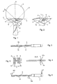
- the table tennis racket comprises a handle 1 extending along a longitudinal axis X.
- the racket further comprises a pallet 2.
- the pallet 2 has a first main face 2a and a second main face 2b opposite the first, the two main faces defining the playing surfaces of the racket.
- the pallet 2 has a peripheral edge 3 connecting the two main faces.
- the pallet comprises a plurality of blind recesses 4 (of which only one is numbered here) which are formed between the two main faces and which open on the peripheral edge 3 of the pallet 2. These recesses 4 make it possible to lighten the racket without drastically reduce the resistance of the racket.
- the racket further comprises a junction zone 5 between the handle 1 and the pallet 2 which here has a thickness identical to that of the pallet 2.
- the junction zone 5 has an orifice 6 passing through the junction zone 5 throughout its thickness.
- the orifice 6 has a roughly elliptical section, the section being defined by a cutting plane parallel to the main faces of the pallet 2.
- the orifice 6 is formed in the junction zone 5 so that a diameter 7 of the section roughly elliptical is inclined relative to the longitudinal axis X that is to say is neither parallel nor perpendicular to the longitudinal axis X.
- the junction zone comprises a reinforcement 8 extending through the orifice 6 from the handle 1 to the pallet 2.
- the reinforcement 8 extends into the orifice 6 so as to separate the orifice into two openings 12, 13 of different sections (said sections also being defined by a cutting plane parallel to the main faces of the pallet 2).
- the reinforcement 8 and the orifice 6 are here shaped so that the section of each of the openings 12, 13 has an area between 1 and 15% of the area of one of the main faces of the pallet 2.
- the section of one of the openings 12 has an area of substantially 3% of that of the first main face 2a and the section of the other of the openings 13 has an area of substantially 2% of that of the first main face 2a.
- the reinforcement 8 is arranged so that a longitudinal direction Y of the reinforcement 8 is inclined relative to the longitudinal axis X of the racket and to the diameter 7 of the orifice 6.
- inclined is meant of course that the longitudinal direction Y is neither perpendicular nor parallel to the diameter 7 and to the longitudinal axis X.
- the reinforcement 8 comprises two first identical ribs 9 which both extend in the longitudinal direction Y of the reinforcement 8.
- the first ribs 9 extend over only a portion of the reinforcement 8.
- the ratio of the length L n of each first rib 9 over the length L r of the reinforcement 8 is here approximately 70%, the lengths of the reinforcement 8 and first ribs 9 being the dimensions said reinforcement 8 and said first ribs 9 in the longitudinal direction Y.
- the first ribs 9 are here arranged on a first main face 11a of the reinforcement 8 so as to each form a flange of said first main face 11a of the reinforcement 8.
- the reinforcement further comprises two second ribs 10 identical to each other and which both extend in the longitudinal direction Y of the reinforcement 8.
- the second ribs 10 are here arranged on a second main face 11b of the reinforcement 8, opposed to the first main face 11a of the reinforcement 8, so as to each form a flange of said second main face of the reinforcement 8.
- the second ribs 10 extend over only a portion of the reinforcement 8 so that each second rib 10 extends respectively under one of the first ribs 9.
- Each second rib 10 is here identical and of the same length as the first rib 9 in which said second rib 10 extends.
- the ratio of the length L n of each second rib 10 to the length L r of the reinforcement 8 is here about 70%, the lengths of the reinforcement 8 and the second ribs 10 being the dimensions of said reinforcement 8 and said second ribs 10 the longitudinal direction Y.
- the reinforcement 8 has a section substantially in H, the section being defined by a transverse sectional plane having for normal the longitudinal direction Y (as more visible at the figure 3 ).
- the ratio of the width l n of each rib to the width l r of the reinforcement 8 is substantially 30%, the widths of the reinforcement 8 and ribs being the dimensions of said reinforcement and said ribs in a second direction which is transverse to the longitudinal direction Y and which belongs to the same plane as said longitudinal direction Y, said plane being parallel to the main faces of the pallet 2.
- the ratio of the thickness in each rib to the thickness e r of the reinforcement 8 is substantially 135%.
- the reinforcement 8, the first ribs 9 and the second ribs 10 are shaped so that the sum of the thickness of the reinforcement 8, a first rib 9 and a second rib 10 is substantially equal to the thickness of the rib. junction area 5 and pallet 2.
- the reinforcement 8 thus has two identical main faces and is symmetrical in the longitudinal direction Y.
- the reinforcement 8 and the orifice 6 are shaped so that the area of the section of the reinforcement 8 according to said cutting plane is between 10 and 50% of the area of the section of the orifice 6 along said section plane.
- said section of the reinforcement 8 has an area of substantially 25% of that of the orifice 6.
- the unitary assembly formed by the pallet 2, the junction zone 5, the handle 1 and the reinforcement 8 with the ribs 9 is molded of plastics material.
- the plastic is polyamide filled with 30% glass fibers.
- the inventors have thus been able to develop a racket according to the invention as described above having the following characteristics: Thickness of the pallet (in millimeters) Mass (in grams) Young's modulus (in kilopascal) Breaking force (in Newton) Elongation at break (in millimeters) 5, 9 111.1 1943 279 58.1
- the values of breaking force and elongation at break are determined according to a test for measuring the resistance implemented using the device illustrated in FIG. figure 6 .
- the device comprises a first fulcrum 101 on the racket at the end of the pallet 2 and a second fulcrum 102 on the racket substantially at 10 millimeters from the end of the handle 1 which is connected to the junction zone 5. A force is then applied to the racket 5 millimeters from the free end of the handle 1.
- the racket according to the invention is thus of a relatively small mass thanks in particular to the recesses 4, the orifice 6 and the material of the unitary assembly.
- the racket also has sufficient strength under normal conditions of use, despite the presence of the orifice 6, thanks to the reinforcement 8 and the ribs 9.
- the reinforcement may be different from what has been described and in particular may have any other shape than that described.
- the reinforcement comprises four ribs
- the reinforcement may comprise a different number of ribs and comprise for example a single rib extending preferably in the center of one of the main faces of the reinforcement according to the longitudinal direction.
- the reinforcement may comprise one or more ribs only on one of its main faces.
- the reinforcement may thus have a section, defined by a sectional plane having normal for the longitudinal direction of the reinforcement, different from that in H described as for example a T-section or U or cross.
- the reinforcement may have a thickness different from that indicated.
- the ribs may have a shape different from that described and include for example a longitudinal portion and a curved portion. Two ribs of the same main face of the reinforcement can thus meet at their curved parts.
- a "rib” will therefore designate a protruding portion of the rest of one of the main faces of the reinforcement and that said portion has significant dimensions as in the embodiment described or smaller dimensions so as to form a simple protruding tongue. It will therefore be understood that, within the meaning of the invention, a groove formed in one of the faces of the reinforcement defines two broad but slightly protruding ribs on either side of the groove, the reinforcement thus comprising two ribs.
- the dimensions of the rib relative to those of the reinforcement may be different from those indicated.
- the rib may have a length of between 30% and 100% of the length of the reinforcement [the length being the dimension in the longitudinal direction Y].
- the rib may have a width of between 10% and 50% of the width of the reinforcement [the width being the dimension in a second direction which is transverse to the longitudinal direction and which belongs to the same plane as said longitudinal direction, which plane is parallel to the main faces of the pallet].
- the rib may have a thickness of between 75% and 175% of the thickness of the reinforcement.
- the dimensions of the openings section relative to those of the pallet may also be different from those indicated.
- the dimensions of the section of the reinforcement relative to those of the orifice may also be different from those indicated.
Landscapes
- Health & Medical Sciences (AREA)
- General Health & Medical Sciences (AREA)
- Physical Education & Sports Medicine (AREA)
- Pallets (AREA)
Applications Claiming Priority (1)
| Application Number | Priority Date | Filing Date | Title |
|---|---|---|---|
| FR1362273A FR3014323B1 (fr) | 2013-12-06 | 2013-12-06 | Raquette de tennis de table comportant un renfort |
Publications (1)
| Publication Number | Publication Date |
|---|---|
| EP2881150A1 true EP2881150A1 (de) | 2015-06-10 |
Family
ID=50179777
Family Applications (1)
| Application Number | Title | Priority Date | Filing Date |
|---|---|---|---|
| EP14195931.2A Withdrawn EP2881150A1 (de) | 2013-12-06 | 2014-12-02 | Tischtennisschläger mit einer Verstärkung |
Country Status (2)
| Country | Link |
|---|---|
| EP (1) | EP2881150A1 (de) |
| FR (1) | FR3014323B1 (de) |
Cited By (2)
| Publication number | Priority date | Publication date | Assignee | Title |
|---|---|---|---|---|
| CN105457246A (zh) * | 2016-02-04 | 2016-04-06 | 鲍金龙 | 乒乓球拍 |
| CN106492428A (zh) * | 2016-11-28 | 2017-03-15 | 渭南师范学院 | 一种带电子监测功能的乒乓球拍 |
Citations (1)
| Publication number | Priority date | Publication date | Assignee | Title |
|---|---|---|---|---|
| US3674268A (en) * | 1970-06-04 | 1972-07-04 | Kenneth S Shellman Sr | Table tennis paddle construction with improved handle means therefor |
-
2013
- 2013-12-06 FR FR1362273A patent/FR3014323B1/fr active Active
-
2014
- 2014-12-02 EP EP14195931.2A patent/EP2881150A1/de not_active Withdrawn
Patent Citations (1)
| Publication number | Priority date | Publication date | Assignee | Title |
|---|---|---|---|---|
| US3674268A (en) * | 1970-06-04 | 1972-07-04 | Kenneth S Shellman Sr | Table tennis paddle construction with improved handle means therefor |
Cited By (3)
| Publication number | Priority date | Publication date | Assignee | Title |
|---|---|---|---|---|
| CN105457246A (zh) * | 2016-02-04 | 2016-04-06 | 鲍金龙 | 乒乓球拍 |
| CN105457246B (zh) * | 2016-02-04 | 2018-12-07 | 鲍金龙 | 乒乓球拍 |
| CN106492428A (zh) * | 2016-11-28 | 2017-03-15 | 渭南师范学院 | 一种带电子监测功能的乒乓球拍 |
Also Published As
| Publication number | Publication date |
|---|---|
| FR3014323A1 (fr) | 2015-06-12 |
| FR3014323B1 (fr) | 2017-02-24 |
Similar Documents
| Publication | Publication Date | Title |
|---|---|---|
| CA2008956C (fr) | Cle de serrage perfectionnee en matiere plastique avec insert metallique | |
| FR3064186A1 (fr) | Raquette de padel | |
| WO1993019817A1 (fr) | Tete de club de golf composee d'un corps creux plastique et d'un element d'obturation metallique | |
| FR2693378A1 (fr) | Perfectionnement pour tête de club de golf du type "fer". | |
| EP0628327B1 (de) | Alpinski mit verbessertem Profil | |
| EP0855201B1 (de) | Gleitbrett | |
| FR2527461A1 (fr) | Ski a couches multiples a construction en sandwich | |
| FR3014323A1 (fr) | Raquette de tennis de table comportant un renfort | |
| FR3057295A1 (fr) | Aube comprenant une plate-forme et une pale assemblees | |
| WO2010094894A1 (fr) | Raquette de tennis comprenant des moyens d'amortissement | |
| FR2615401A1 (fr) | Raquette presentant un col perfectionne | |
| FR2906153A1 (fr) | Planche de glisse pour la neige | |
| FR2495477A1 (fr) | Raquette de tennis | |
| EP3651661A1 (de) | Element zur herstellung einer gefässklammer und damit hergestellte gefässklammer | |
| EP1790395B1 (de) | Roll- oder gleitbrett | |
| FR2934960A3 (fr) | Raquette creuse | |
| EP2845692B1 (de) | Griff für Handschlagwerkzeug, Handschlagwerkzeug und Herstellungsverfahren eines Handschlagwerkzeugs | |
| WO2001007718A1 (fr) | Glissiere de securite pour route ou analogue comportant des lisses en bois renforcees par des fibres | |
| FR3058326A1 (fr) | Dispositif d'extremite inferieure d'un baton de sport | |
| EP1496763A2 (de) | Sohlenaufbau für schuhwerk | |
| EP2889062A1 (de) | Tischtennisschläger | |
| WO2001002649A1 (fr) | Dispositif de securite routiere, pieces constitutives et leur procede de fabrication | |
| EP2213339B1 (de) | Ski, der eine Schwingungsdämpfungseinrichtung umfasst | |
| EP2602008B1 (de) | Schneegleitbrett | |
| EP1557635B1 (de) | Satz von Bogenteilen für einen Sportbogen und Herstellungsverfahren für dieselben |
Legal Events
| Date | Code | Title | Description |
|---|---|---|---|
| PUAI | Public reference made under article 153(3) epc to a published international application that has entered the european phase |
Free format text: ORIGINAL CODE: 0009012 |
|
| 17P | Request for examination filed |
Effective date: 20141202 |
|
| AK | Designated contracting states |
Kind code of ref document: A1 Designated state(s): AL AT BE BG CH CY CZ DE DK EE ES FI FR GB GR HR HU IE IS IT LI LT LU LV MC MK MT NL NO PL PT RO RS SE SI SK SM TR |
|
| AX | Request for extension of the european patent |
Extension state: BA ME |
|
| STAA | Information on the status of an ep patent application or granted ep patent |
Free format text: STATUS: THE APPLICATION IS DEEMED TO BE WITHDRAWN |
|
| 18D | Application deemed to be withdrawn |
Effective date: 20151211 |