EP2881132A1 - Dispositif d'injection doté d'un organe de dosage et d'un ressort de versement précontraint - Google Patents
Dispositif d'injection doté d'un organe de dosage et d'un ressort de versement précontraint Download PDFInfo
- Publication number
- EP2881132A1 EP2881132A1 EP13195951.2A EP13195951A EP2881132A1 EP 2881132 A1 EP2881132 A1 EP 2881132A1 EP 13195951 A EP13195951 A EP 13195951A EP 2881132 A1 EP2881132 A1 EP 2881132A1
- Authority
- EP
- European Patent Office
- Prior art keywords
- dose
- housing
- spring
- drive
- relative
- Prior art date
- Legal status (The legal status is an assumption and is not a legal conclusion. Google has not performed a legal analysis and makes no representation as to the accuracy of the status listed.)
- Granted
Links
Images

Classifications
-
- A—HUMAN NECESSITIES
- A61—MEDICAL OR VETERINARY SCIENCE; HYGIENE
- A61M—DEVICES FOR INTRODUCING MEDIA INTO, OR ONTO, THE BODY; DEVICES FOR TRANSDUCING BODY MEDIA OR FOR TAKING MEDIA FROM THE BODY; DEVICES FOR PRODUCING OR ENDING SLEEP OR STUPOR
- A61M5/00—Devices for bringing media into the body in a subcutaneous, intra-vascular or intramuscular way; Accessories therefor, e.g. filling or cleaning devices, arm-rests
- A61M5/178—Syringes
- A61M5/31—Details
- A61M5/315—Pistons; Piston-rods; Guiding, blocking or restricting the movement of the rod or piston; Appliances on the rod for facilitating dosing ; Dosing mechanisms
- A61M5/31533—Dosing mechanisms, i.e. setting a dose
- A61M5/31545—Setting modes for dosing
- A61M5/31548—Mechanically operated dose setting member
- A61M5/3155—Mechanically operated dose setting member by rotational movement of dose setting member, e.g. during setting or filling of a syringe
- A61M5/31553—Mechanically operated dose setting member by rotational movement of dose setting member, e.g. during setting or filling of a syringe without axial movement of dose setting member
-
- A—HUMAN NECESSITIES
- A61—MEDICAL OR VETERINARY SCIENCE; HYGIENE
- A61M—DEVICES FOR INTRODUCING MEDIA INTO, OR ONTO, THE BODY; DEVICES FOR TRANSDUCING BODY MEDIA OR FOR TAKING MEDIA FROM THE BODY; DEVICES FOR PRODUCING OR ENDING SLEEP OR STUPOR
- A61M5/00—Devices for bringing media into the body in a subcutaneous, intra-vascular or intramuscular way; Accessories therefor, e.g. filling or cleaning devices, arm-rests
- A61M5/178—Syringes
- A61M5/20—Automatic syringes, e.g. with automatically actuated piston rod, with automatic needle injection, filling automatically
-
- A—HUMAN NECESSITIES
- A61—MEDICAL OR VETERINARY SCIENCE; HYGIENE
- A61M—DEVICES FOR INTRODUCING MEDIA INTO, OR ONTO, THE BODY; DEVICES FOR TRANSDUCING BODY MEDIA OR FOR TAKING MEDIA FROM THE BODY; DEVICES FOR PRODUCING OR ENDING SLEEP OR STUPOR
- A61M5/00—Devices for bringing media into the body in a subcutaneous, intra-vascular or intramuscular way; Accessories therefor, e.g. filling or cleaning devices, arm-rests
- A61M5/178—Syringes
- A61M5/31—Details
- A61M5/315—Pistons; Piston-rods; Guiding, blocking or restricting the movement of the rod or piston; Appliances on the rod for facilitating dosing ; Dosing mechanisms
- A61M5/31565—Administration mechanisms, i.e. constructional features, modes of administering a dose
- A61M5/31576—Constructional features or modes of drive mechanisms for piston rods
- A61M5/31578—Constructional features or modes of drive mechanisms for piston rods based on axial translation, i.e. components directly operatively associated and axially moved with plunger rod
- A61M5/3158—Constructional features or modes of drive mechanisms for piston rods based on axial translation, i.e. components directly operatively associated and axially moved with plunger rod performed by axially moving actuator operated by user, e.g. an injection button
-
- A—HUMAN NECESSITIES
- A61—MEDICAL OR VETERINARY SCIENCE; HYGIENE
- A61M—DEVICES FOR INTRODUCING MEDIA INTO, OR ONTO, THE BODY; DEVICES FOR TRANSDUCING BODY MEDIA OR FOR TAKING MEDIA FROM THE BODY; DEVICES FOR PRODUCING OR ENDING SLEEP OR STUPOR
- A61M5/00—Devices for bringing media into the body in a subcutaneous, intra-vascular or intramuscular way; Accessories therefor, e.g. filling or cleaning devices, arm-rests
- A61M5/178—Syringes
- A61M5/31—Details
- A61M2005/3125—Details specific display means, e.g. to indicate dose setting
- A61M2005/3126—Specific display means related to dosing
Definitions
- the invention relates to an injection device for administering a liquid product, in particular a medicament, such. B. insulin for diabetes therapy.
- a liquid product in particular a medicament, such. B. insulin for diabetes therapy.
- the invention relates to a drive and metering device for such an injection device.
- the term "medicament” includes any fluid medical formulation suitable for controlled administration by an agent, such as an oral fluid.
- a cannula or hollow needle for example comprising a liquid, a solution, a gel or a fine suspension containing one or more medicinal agents.
- Drug may be a single drug composition or a premixed or co-formulated multi-drug composition from a single container.
- Drug includes drugs such as peptides (eg, insulins, insulin-containing drugs, GLP-1 containing as well as derived or analogous preparations), proteins and hormones, biologically derived or active agents, hormone or gene based drugs, nutritional formulas, enzymes, and other substances both in the art solid (suspended) or liquid form but also polysaccharides, vaccines, DNA or RNA or Oglionukleotide, antibodies or parts of antibodies and suitable base, excipients and carriers.
- drugs such as peptides (eg, insulins, insulin-containing drugs, GLP-1 containing as well as derived or analogous preparations), proteins and hormones, biologically derived or active agents, hormone or gene based drugs, nutritional formulas, enzymes, and other substances both in the art solid (suspended) or liquid form but also polysaccharides, vaccines, DNA or RNA or Oglionukleotide, antibodies or parts of antibodies and suitable base, excipients and carriers.
- drugs such as peptides (
- the invention is a development of the invention from the WO 2013/144021 A1 ,
- the invention is based on a drive mechanism for an injection device for administering a liquid medicament or product.
- the drive mechanism points a housing on.
- the housing is preferably sleeve-shaped and / or elongated.
- the housing can be z. B. extend along its longitudinal axis.
- the housing can optionally accommodate a product container or even form the product container.
- the housing can be one or more parts.
- the housing may form a proximal housing part which comprises or comprises the drive and metering device.
- the housing may further include a product container holder, which holds the product container, such. B. a carpule, receives and is connected to the housing or the proximal housing part. This connection may be such that the product container holder and the housing or the proximal housing part after connection unsolvable, d. H. only by destruction of fasteners is solvable.
- Such a solution is particularly advantageous in the case of disposable injection devices which, after the product contained in the product container has been completely poured out, are discarded as a whole.
- the product container holder can also be releasably secured to the housing, whereby it is possible, although less preferred, to use the drive and metering device, if necessary several times, d. H. replace an empty product container with a filled product container.
- the housing preferably serves to be gripped by the user of the device.
- the housing may have a substantially cylindrical shape.
- the housing may, for. B. a pointing device, in particular a window, by means of which or by which a currently set dose, preferably from a scale of a dose setting element, can be read.
- the drive and metering device which in particular forms an injection device together with the product container, comprises, in addition to a housing, a dose indicator element, over the circumference of which a dose scale is arranged.
- the dose indicator may e.g. B. be annular in cross section.
- the dose indicator may e.g. A dose indicator drum or dose indicator ring.
- the dose scale may extend over the circumference of the dose indicator element, preferably helically.
- the dose scale preferably comprises a plurality of values arranged in a row and giving the dose scale. Preferably, these are numerical values which indicate the desired product dose in international units (IU) or in milligrams.
- the dose scale without slope over the circumference of the dose indicator element such as.
- the dose indicator ring be arranged, with the scale values then repeat after a rotation of the dose indicator element.
- the dose indicator in particular the dose display drum, with more than one revolution can be rotated without repeating the scale values, which can advantageously the scale values greater or more scale values can be displayed.
- the drive and metering device further comprises a pointing device, wherein the dose indicator element for adjusting the dose to be administered relative to the pointing device and in particular about an axis of rotation, which preferably corresponds to the longitudinal axis of the drive and metering device and / or the dose indicator element, is rotatable.
- This may be a pure rotational movement, d. H. to act a rotary motion without superimposed axial movement.
- the rotational movement is superimposed on an axial movement, whereby the dose indicator element for adjusting the dose to be administered can be screwed relative to the pointing device.
- a screwable dose indicator can be advantageously combined with a helical dose scale, wherein the screwing and the dose scale advantageously have the same slope.
- a dose display element rotatable without axial movement can advantageously be combined with a gradient-free dose scale.
- a value of the dose scale is read, which corresponds to the set dose.
- the pointing device can, for. B. may be a window that may be formed by a breakthrough in the housing or by a transparent insert.
- the pointing device can be an arrow or have an arrow, the z. B. in addition to the window marked the value of the dose scale, which corresponds to the set dose. This is z. B. advantageous if in the window still another value appears at least partially, to ensure a clear dose selection.
- the pointer can z. B. a projection or a print or a notch or the like.
- the drive and metering device comprises a metering member which is designed, for example, as a metering button and can optionally be referred to as a dose setting member.
- the dosing member is preferably accessible to the user (patient, doctor, medical assistant) of the drive and metering device and preferably forms an outer, in particular accessible from the outside surface of the drive and metering device.
- the dosing member is preferably from User gripped and relative to the housing and in particular the pointing device about an axis of rotation, which preferably corresponds to the longitudinal axis of the example elongated drive and metering device, twisted.
- the dosing member is preferably axially fixed to the housing, in particular displaceable along a longitudinal axis of the housing, thereby advantageously facilitating the intuitive handling of the device by the user, since he only needs to perform a rotational movement of the dosing for dose adjustment.
- the dose indicating element may be rotationally fixed, at least during dose setting, but e.g. axially slidably connected to the dosing or be coupled.
- the dose indicator element is also rotated by a rotation angle about this rotation angle when the dosing member is rotated.
- the drive and metering device can be an actuator, e.g. in the form of an actuating button.
- the actuator may form an outer surface of the drive and metering device and / or be accessible from the outside.
- the actuator may be formed at the proximal, in particular rear end of the drive and metering device or form this end.
- the actuator can be advantageously in this way with the thumb of the hand, which presses the housing surround press in particular. By releasing the actuator, the operation can be terminated.
- actuate is meant the displacement of the actuator in the drive and metering device, in particular in the distal direction, whereby in particular a product discharge can be effected.
- the actuating member is advantageously displaceable relative to the dosing member and in particular can be accommodated axially displaceably by the dosing member.
- the actuator can advantageously against the force of a spring, in particular a reset or clutch spring slidably, in particular be actuated, whereby this spring is tensioned. By releasing this spring can reset the actuator, in particular relative to the dosing, in particular in the proximal direction or out of the drive and dosing, move.
- a spring in particular a reset or clutch spring slidably, in particular be actuated, whereby this spring is tensioned.
- the drive and metering device further comprises a bearing member with which the dose indicator is engaged.
- This engagement advantageously effects the rotational or screwing movement of the dose indicating element relative to the pointing device.
- the engagement between the dose indicating element and the bearing element may be a threaded engagement.
- the bearing element can have an external thread and the dose indicator element an internal thread, wherein these threads mesh with each other and thereby cause the dose indicator element to be screwed relative to the bearing element.
- the dose indicator element is rotatable or screwable between a maximum dose position and a zero dose position.
- the zero dose position advantageously, the dose or digit "0" in the pointing device can be read.
- the maximum dose position the maximum product dose that can be distributed with the drive and metering device can be read.
- the dose indicating element may be locked against rotation in one direction of rotation, namely the direction of rotation that would cause a dose to be set less than zero.
- the dose indicator may preferably be moved only in the direction of rotation which causes an increase in the dose.
- the dose indicator is preferably blocked against rotation in one direction of rotation, namely the direction of rotation that would cause the setting of a dose beyond the maximum adjustable dose.
- the dose indicator element can be rotated in the maximum dose position, in particular only in the direction of rotation, which causes a reduction in the product dose.
- the dose indicator may e.g. B. have a stop which abuts in the zero dose position to a counter-stop and thus prevents rotation in one direction.
- the same or an additional stop of the dose indicating element may prevent the rotation of the dose indicating element beyond the maximum dose.
- a further counter-stop namely a maximum dose counter-attack can be provided.
- the other counterstop may be referred to as a zero dose counterstop.
- the dose indicator may have a zero dose stop for the zero dose counter-stop and a maximum dose stop for the maximum dose counter-stroke.
- the stop or the stops act in the circumferential direction and / or in the axial direction.
- the drive and metering device according to the first aspect may preferably be such that the bearing element is displaceable together with the dose indicator element relative to the housing and along the axis of rotation, in particular in the distal direction.
- This aspect may benefit the drive and metering device according to a second aspect described herein further training.
- the dose indicating element may have a thread which is engaged with the housing. As a result, although the dose indicator element can be screwed back and forth relative to the housing, it can not be displaced independently of the screwing movement with a particularly pure axial movement.
- the actuator is coupled to the bearing member such that displacement of the actuator relative to the housing and / or the metering member causes displacement of the bearing member relative to the housing and / or the metering member, particularly along the longitudinal axis of the drive and metering device.
- the dose indicator element By virtue of the fact that the dose indicator element is in engagement with the bearing element and the bearing element can be displaced relative to the housing and along the axis of rotation, the dose indicator element can also be moved relative to the housing and along the axis of rotation independently of the turning or screwing movement which the Move the dose indicator at the dose setting.
- the drive and metering device according to the second aspect can in principle also advantageously be combined with the alternative dose indicator element which is in threaded engagement with the housing or a housing-fixed element.
- the bearing element may be formed by the housing or be part of the housing, wherein the bearing element then z. B. can be rotationally and axially fixed with respect to the rest of the housing.
- the bearing element has been displaced together with the dose indicator element.
- This allows the user to check in which operating state the drive and metering device is located, ie. H. Whether the drive and metering device in particular the actuator is actuated for a discharge or unconfirmed.
- the actuating member and / or the bearing element can be displaceable together with the dose indicator element relative to the pointing device, the housing and along the axis of rotation.
- a mark different from the dose scale may appear when the bearing element is displaced.
- the marker is preferably arranged on the dose indicator. If the bearing element is unshifted, in particular the drive and metering device for the product distribution is unconfirmed, the marking can be arranged outside of the pointing device, such. From a housing or other element be covered.
- the marking can emerge from the covered area, so that it appears or can be read, in particular, on or in the pointing device. If the operation of the drive and metering device is interrupted or terminated, the bearing element can return to the original position, whereby the marking is preferably removed from the area of the pointing device and in particular concealed.
- the actuator or / and the bearing element may be displaceable relative to the housing and along the axis of rotation together with the dose indicator element and the pointing device.
- the pointing device can, for. B. be a panel or at least fulfill the function of a panel.
- the pointing device may be at least axially fixed, preferably also non-rotatably connected to the bearing element.
- the bearing element can form the pointing device.
- the pointing device is a separate part from the bearing element.
- the pointing device can, for. B. be sleeve-shaped.
- the displacement of the bearing element can cause that in the area of the pointing device a different mark from the dose scale appears, which is arranged or formed on or on the pointing device.
- the pointing device can be arranged inside the housing.
- the marking of the pointing device can be hidden in the unactuated state of the drive and metering device of the housing or other element. If the drive and metering device, in particular the actuating element, is actuated so that the dose indicator element is displaced together with the pointing device, the marking can emerge from its cover, so that the marking can be viewed or read. If the operation is interrupted or terminated, the dose indicator can be moved back together with the pointing device and the bearing element to its original position, so that the mark is again arranged under the cover.
- a spring in particular a clutch or return spring are tensioned.
- the bearing element can be displaced upon actuation against the force of a particular such spring, in particular from an unactuated position to an actuated position.
- the spring can z. B. be a helical or spiral spring, which acts as a compression spring.
- This spring also causes the bearing element to be reset to its initial or unactuated position when the operation is interrupted or terminated.
- the bearing element is displaced in the distal direction during actuation. By means of the spring, the bearing element is moved back in the proximal direction when the operation is interrupted or terminated.
- the actuation of the actuator in particular causes the bearing element is displaced together with the dose indicator element relative to the housing and along the axis of rotation.
- the actuation of the actuator can cause a propulsion member whose distal end is provided to act on a piston of the attached to the drive and metering device or attachable product container, is moved in the distal direction, in particular delivery direction.
- the actuator may, for. At the proximal, d. H. be arranged rear end of the drive and metering device or form the proximal end of the drive and metering device.
- the actuating element can be arranged laterally on the housing and / or between the distal end and the proximal end of the drive and metering device.
- the actuator may be formed in the manner of an operating knob.
- the actuator is preferably displaced relative to the housing or dosing member upon actuation.
- the user of the device can advantageously benefit from the actuator e.g. with the thumb of his hand, which surrounds the housing of the drive and metering device actuate.
- the actuator is preferably connected to the bearing element so that it shifts the bearing element when actuated, in particular via a coupling member, the z. B. axially fixed and can be rotatably connected to the bearing element.
- actuation of the actuator may cause the dose indicator to be rotated, in particular screwed, relative to or on the bearing member or housing, particularly in a direction that counters the values of the dose scale moving past the pointing device as it rotates.
- the angle of rotation of the dose indicator element and the delivery stroke of the advancing member are in a proportional relationship, in particular at any time during the dose distribution. This allows a real-time display to be made which counts back to the dose distribution until it finally reaches 0, with the distribution of that dose then being completed. If the operation for the distribution during of turning back the dose indicating element is interrupted, the dose indicating element indicates the remaining amount still required for the distribution of this dose.
- the drive and metering device can be configured such that the energy required for turning back the dose indicator element and / or the displacement of the advancing member in the distal direction is applied manually, in particular by a force acting on the actuator force of the user.
- the dose setting member in particular the dosing button, can be unscrewed from the proximal end of the housing for dose adjustment, being screwed back into the housing for dose distribution by actuation of the actuator.
- the drive and metering device can be designed such that the energy required for turning back the dose indicator element and / or the displacement of the advancing member in the distal direction automatically, in particular by a spring contained in the drive and metering device, in particular discharge in which the required energy is stored or can be provided.
- the spring energy stored in the dispenser spring may be delivered to the dose indicator or / and propulsive member such that the dose indicator is rotated backward and the advancer member is displaced distally.
- the discharge can z. B. so coupled to the dosing that a rotation of the dosing biases the discharge during the dose setting.
- the spring can then store the energy required for the set dose.
- the spring can already be biased at delivery of the drive and metering device with so much energy that the energy is sufficient for several distributions of the product dose, in particular sufficient for the distribution of the entire distributable from the product container product.
- the dosing member may be decoupled from the spring at the dose setting, i. H. not be coupled to the discharge spring so that rotation of the dosing member causes a tensioning of the spring. This allows the dosing member for the user in the dose setting rotate with significantly less force.
- the dosing in particular the Dosierknopf can surround the actuator, in particular the actuating button or record.
- the dosing and the Actuator form the proximal end of the drive and metering device.
- the actuating member for the actuation is displaceable relative to the dosing member.
- the dosing member may preferably be arranged axially fixed relative to, but rotatable relative to, in particular on the housing.
- the drive - And metering device have a propelling member, the distal end is provided to act on a piston, in particular indirectly or preferably directly.
- the piston may be part of a attached to the drive and metering device or attachable product container, such.
- the propulsion member can be referred to in a broader sense as a piston rod, wherein the propulsion member does not necessarily have to be solid, but also hollow, such. B. can be configured sleeve-shaped.
- the propulsion member can optionally a z. B. rotatable flange, which presses against the piston. Generally, it is preferred that the distal end of the propulsion member press against the piston.
- the propulsion member is preferably displaceable relative to the housing along the longitudinal axis of the drive and metering device.
- the drive and metering device can have an abutment and preferably a guide, wherein the advancing member is movable relative to the abutment and preferably also relative to the guide in one direction, in particular in the distal direction or in the dispensing direction, to a release of the adjusted product dose cause.
- the propulsion member may be guided straight or axially by means of or on the guide, along the longitudinal axis of the drive and metering device.
- the propulsion member may be non-rotatable relative to the abutment and / or the guide and / or the housing.
- the propulsion member may be rotatable relative to the abutment or housing combined with longitudinal movement, ie, be screwable relative to the abutment, although less preferably.
- the guide and / or the abutment can be formed by the housing, in particular a sleeve-shaped housing part or an eg sleeve-shaped, housing-fixed element.
- the propulsion member and the guide formed in particular by the housing may, for example, be indirectly engaged in an immediate or via an intermediate member, which prevents rotation of the propulsion member relative to the abutment or the housing, but an axial movement or a screwing movement of the propulsion member relative to the abutment or the housing allowed.
- the leadership can z. B. be an axial guide or a thread with a non-self-locking thread pitch.
- the guide or the abutment or / and the guide forming housing portion may preferably surround the propulsion member, such as. B. sleeve-shaped and / or be fixed to the housing or formed by the housing. Between this sleeve-shaped housing part and an outer, preferably also sleeve-shaped housing part, an annular gap may be formed, which has the advantage that an optionally present dose indicator element, in particular dose display drum, can be accommodated therein. This causes the length of the drive and metering device can be kept low.
- the drive and metering device at least one, such. B. exactly one, two or three, acting between the driving member or a rotary member and the abutment and in particular arranged discharge spring.
- the at least one spring can be z. B. on the propulsion member and / or the abutment.
- the z. B. single discharge spring with its distal end on the driving member and with its proximal end supported on the abutment.
- the at least one discharge spring can be arranged inside the guide or the sleeve-shaped housing part forming the guide. If the advancing member is sleeve-shaped, the at least one discharge spring can be arranged within the advancing member.
- a first discharge spring and a second discharge spring may in particular be arranged kinematically between the advancing member and the guide or the sleeve-shaped housing part forming the guide.
- the second discharge spring can be arranged concentrically to the first discharge spring.
- the first discharge and the second discharge can z. B. be connected in parallel or in series.
- Shunt springs connected in parallel mean, in particular, that the first and second discharge springs can each be supported with their distal end on the advancing member and each with its proximal end on the abutment. This allows the spring constants of the first and second discharge spring to add up to a total spring constant.
- series connected distribution springs means in particular, that the distal end of one of the first and second discharge spring presses against the proximal end of the other from the first and second discharge spring, in particular directly or preferably indirectly, such. B. via the intermediate member.
- the first discharge spring is supported on the abutment and the intermediate member and the second discharge spring on the intermediate member and the advancing member from.
- the distal end of the first delivery spring can be arranged distally of the proximal end of the second delivery spring. Due to the intermediate member, the spring force of the first spring can be transmitted from its distal end to the proximal end of the second discharge spring.
- the intermediate member may be sleeve-shaped and arranged in an annular gap between the first and second discharge spring. In series connected distribution springs allow, over a relatively long spring travel a relatively constant spring force.
- the at least one discharge spring in particular the first and second discharge springs, can be a helical or helical spring which acts as a compression spring or as a torsion spring.
- the at least one ejection spring is biased and thus acts on the propulsion member, which it tries, the propulsion member relative to the abutment in the distal direction, d. H. to move in the direction of delivery.
- the drive and metering device is designed so that after each individual distribution or distribution of the product dose, the next dose to be dispensed is readjusted.
- the energy-preloaded spring required to deliver the maximum amount of product dispensed from the product container allows for easier dose adjustment because of dose adjustment relative to the housing rotatable dosing is then easier rotatable, because the spring need not be biased at the dose setting. This increases the ease of use for the user of the device.
- the drive and metering device may further include a rotary member, the rotation of which causes the drive spring to deliver energy to the propelling member, thereby moving the propelling member in the distal direction.
- the rotary member preferably performs the function of a control member, wherein the rotation of the rotary member causes by a certain angle of rotation, the advance of the advancing member to a certain Aus thoroughlyhub.
- the rotary member may be coupled to the actuator such that upon actuation of the product dispensing actuator, it is released for rotation relative to the housing and is locked for non-actuation of the actuator for rotation relative to the housing.
- at least one clutch may be arranged, which causes the release and blocking of the rotation of the rotary member relative to the housing.
- the at least one clutch by operating the actuator release the rotation of the rotary member relative to the housing and block the rotation of the rotary member relative to the housing by releasing the actuator.
- the at least one spring may include a first helical compression spring and a second helical compression spring, wherein the first compression spring on the abutment and an intermediate member and the second compression spring supported on the intermediate member and the propelling member.
- the intermediate member may rotatably couple the propulsion member with the housing.
- the first compression spring can be supported with its distal end, for example on the intermediate member and its proximal end, for example, on the abutment.
- the second compression spring can be supported with its distal end, for example on the driving member and with its proximal end, for example on the intermediate member.
- the first compression spring and the second compression spring are connected in series. Under a compression spring acting as a compression spring helical spring is understood.
- the intermediate member may, for example, be annular and surround the propulsion member. In particular, the intermediate member may be arranged in an annular gap between an inner sleeve of the housing, which forms the guide, and the driving member.
- the intermediate member may be in engagement with the housing, in particular the inner sleeve and / or the guide in such a way that the intermediate member is displaceable relative to the housing along the longitudinal axis and rotationally fixed about the longitudinal axis.
- the intermediate member may be in engagement with the propelling member such that the intermediate member is slidable relative to the propelling member along the longitudinal axis and non-rotatable about the longitudinal axis. As a result, the propulsion member is secured against rotation via the intermediate member connected to the housing or coupled.
- the intermediate member is preferably in a floating position between the first spring and the second spring, d. H. in that the position of the intermediate member is such that the forces exerted on the intermediate member by the first spring and by the second spring cancel each other out.
- first compression spring surrounding the propulsion member and the second compression spring surrounding the propulsion member.
- first compression spring and the second compression spring can be arranged in the annular gap between the inner sleeve of the housing and the propulsion member.
- the outer diameter of the first compression spring may be larger than the outer diameter of the second compression spring. This can be optimized in terms of a space-saving design with the first compression spring with respect to a high spring constant and with the second compression spring.
- the first compression spring surround the propulsion member and the propulsion member surround the second compression spring.
- the first compression spring may be arranged in the annular gap between the housing, in particular the inner sleeve, and the propulsion member.
- the second compression spring may be arranged in the annular gap between the rotary member and the driving member. This makes it possible to achieve a space-saving design, at least for the area in which the second compression spring is arranged.
- the intermediate member may extend through an elongated slot extending along the longitudinal axis in the wall of the sleeve-shaped driving member.
- the slot can thereby simultaneously serve as a guide or as a longitudinal guide for the intermediate member on the driving member.
- the first spring may be supported on the portion of the intermediate member which is located outside of the propulsion member, wherein the second compression spring may be supported on the portion of the intermediate member which is located within the propulsion member. The intermediate member is displaced during product dispensing in the slot.
- the second compression spring is arranged distally of the first compression spring.
- the proximal end of the second compression spring can be arranged distally of the distal end of the first compression spring.
- the second compression spring may preferably have a smaller outer diameter than the inner wall of the product container, on which the piston of the product container is displaceable is applied. Due to the small outer diameter can be advantageously achieved that accidental contact of the compression spring is avoided by a sufficient distance to the inner wall.
- the second compression spring may be arranged to be in the product container when the piston rod is displaced to dispense the product in the product container.
- the intermediate member may be adjusted in position with respect to the product container such that it is spaced along the longitudinal axis from a proximal end of the product container or contacts the proximal end of the product container when the maximum amount of product dispensed from the product container is dispensed. If the intermediate member does not contact the proximal end of the product container during product dispensing, it is ensured that both compression springs contribute to propulsion of the piston. If the intermediate member comes into contact with the distal end of the product container during product dispensing, only the second compression spring can contribute to the discharge, which can be quite advantageous in special applications.
- the advancing member may have a shoulder against which the at least one spring, in particular with its distal end, is supported.
- the at least one spring may be a single compression spring, d. H. a coil spring, which acts as a compression spring be.
- a portion of the advancing member extending distally of the shoulder along the longitudinal axis may have a length measured along the longitudinal axis which is greater than the distance between the proximal end of the product container and the piston when the piston is in the position in which the in the maximum amount of product that can be distributed is distributed to the product container.
- the compression spring can be arranged only in the region proximal to the shoulder, wherein no further spring needs to be arranged in the region distal of the shoulder. This can be achieved particularly advantageous that the area distal to the shoulder can be designed to save space.
- the shoulder may be in a rotationally fixed and axially displaceable engagement with the housing.
- the shoulder can firmly connect an inner sleeve of the advancing member and an outer sleeve of the advancing member, wherein the at least one compression spring can be arranged in the annular gap formed between the inner sleeve and the outer sleeve.
- the outer sleeve can be in a rotationally fixed and axially displaceable engagement with the housing, in particular the inner sleeve of the housing or the guide. This will prevents rotation of the propulsion member relative to the housing, but allows displacement along the longitudinal axis.
- the at least one spring may be a torsion spring, in particular a helically wound from a band-shaped material spring, which is supported on the rotary member and the abutment.
- a spring can be referred to as a spiral or clock spring.
- the biased torsion spring generates a torque between the rotary member and the abutment, wherein the torque tries to rotate the rotary member relative to the abutment or the housing about the longitudinal axis.
- the torsion spring and preferably also the abutment for the torsion spring on which the torsion spring is supported, may be disposed distally of a dose indicator element and / or a bearing member displaceable relative to the housing along the longitudinal axis and threadedly engaged with a dose indicator.
- a dose indicator element and the bearing element for the embodiment of the dose indicator element and the bearing element, reference is made to the remaining description of this application.
- the rotary member may be rotatably and axially slidably connected to the propelling member.
- the rotary member may, for example, be sleeve-shaped and surround the advancing member.
- the propulsion member and the rotation member may be connected so that the rotation member is rotatable and axially displaceable with respect to the propulsion member.
- the propelling member may then, for example, with its external thread in a threaded engagement with the housing or a housing-fixed element.
- the driving member is screwed to the thread of the housing or the housing-fixed member along the longitudinal axis, whereby for example the product distribution can be made, d. H. the piston in the product container can be displaced in the distal direction.
- the propulsion member for example, rod-shaped, in particular as a piston rod are performed, whereby it maintains a sufficient distance to the inner wall of the product container, when the propulsion member is moved into the product container.
- the angle of rotation of the rotary member may be proportional to the delivery stroke of the piston or of the advancing member. This can be achieved by the selective blocking or release of the rotary member.
- the rotary member can be in engagement, in particular a threaded engagement with the advancing member.
- the thread pitch of this thread engagement is achieved that z. B. in a complete revolution of the rotary member relative to the housing, the driving member of the discharge spring is displaceable by a stroke corresponding to the thread pitch.
- the rotary member may include or be a threaded rod and the propelling member may be a threaded nut, with the thread of the threaded nut engaging the threads of the threaded rod.
- the rotary member may include or be a threaded nut and the male member may be a threaded rod, with the thread of the threaded nut engaging the threads of the threaded rod.
- the rotary member is axially fixed with respect to the housing or may at least in one, preferably in the distal direction axially fixed to the housing or a housing-fixed element, such as. B. support the abutment.
- the rotational member during setting a dose, d. H. in the unactuated state in particular by means of at least one clutch, in particular a first clutch rotatably connected to the housing and is rotated during operation of the device for dispensing the product dose relative to the housing or is rotatable.
- the dose indicating element in particular the dose indicating drum, may optionally be in threaded engagement with the housing or an element fixed to the housing.
- the dose indicating element in particular the dose indicating drum, may be used during the setting of a dose, i. H. be rotatable in the unactuated state of the drive and metering device or the actuator relative to the rotary member.
- the dose indicating element is rotationally fixed and e.g. axially movable, or non-rotatably connected to the rotary member, in particular with the at least one clutch, in particular a second clutch.
- the discharge spring causes the dose indicator element to be in its zero-dose position screwed back, in particular via the rotary member and preferably via a coupling member, which is preferably arranged rotationally fixed but axially displaceable with respect to the dose indicator element.
- the coupling member and the dose indicating element may be in a rotationally fixed engagement allowing axial movement between the dose indicating element and the coupling member.
- This intervention can z. B. be effected by means of a longitudinal guide.
- the coupling member is axially fixed but rotatably connected to the bearing element.
- the first clutch may be arranged kinematically between the housing, in particular the bearing element, and the rotary member.
- the first clutch is engaged during adjustment of the product dose or with the actuator unactuated, whereby the rotary member is rotationally fixed relative to the housing.
- the first clutch is disengaged, whereby the rotary member is rotatable relative to the housing.
- the first coupling may have a first coupling structure, which is rotationally connected to the housing, in particular formed by the housing or the bearing element, and a second coupling structure, which is rotationally connected to the rotary member, in particular of the rotary member is formed.
- the first coupling structure may be or have a toothing, wherein the second coupling structure may be or have a toothing.
- the teeth of the first coupling structure and the second coupling structure can engage positively with engaged first clutch.
- the first coupling structure may be an outer toothing, wherein the second coupling structure may be an internal toothing.
- the first coupling structure may be an internal toothing, wherein the second coupling structure may be an external toothing.
- the second coupling can be arranged between a sleeve-shaped coupling member which, for example, can be connected in a rotatable and axially fixed manner to the bearing element, in particular in engagement, and can be arranged in the rotary member.
- the second clutch is disengaged during adjustment of the product dose or with the actuator unactuated, thereby allowing the coupling member to be rotated relative to the rotary member.
- the second clutch is engaged. This achieves in particular that the rotary member and the coupling member are rotationally connected.
- the coupling member can thus of the Rotating member to be rotated.
- the second clutch may comprise a third coupling structure which is connected in a rotationally secured manner to the coupling member, in particular formed by the coupling member, and a fourth coupling structure, which is rotationally connected to the rotary member, in particular formed by the rotary member.
- the third coupling structure may be or have a toothing, wherein the fourth coupling structure may be or have a toothing.
- the teeth of the third and fourth coupling structure can positively engage when the second clutch is engaged.
- the third coupling structure may be an internal gear, wherein the fourth coupling structure may be an external gear.
- the third coupling structure may be an outer toothing, wherein the fourth coupling structure may be an internal toothing.
- the toothings for the second coupling structure and the fourth coupling structure can be separate toothings from each other.
- the second coupling structure and the fourth coupling structure can be formed by a common toothing.
- the first and the second clutch can be coordinated so that the actuator between the unactuated position and the actuated position can take a, for example, first, intermediate position in which the first clutch is engaged and the second clutch is engaged.
- This has the advantageous effect that the rotation of the coupling member is released by the drive spring only when it is ensured that the rotation member is rotatably coupled to the coupling member.
- a malfunction of the device is advantageously avoided, which could occur if the second clutch is not engaged and the first clutch is already disengaged.
- the drive and metering device preferably has a third clutch, which is arranged between the dose setting member and the coupling member.
- the third clutch is engaged during adjustment of the product dose or with the actuator unactuated, whereby the coupling member and dose setting member are secured against rotation with respect to each other.
- the third clutch is disengaged whereby the coupling member is rotatable relative to the dose setting member by means of the biased drive spring.
- the third coupling may have a fifth coupling structure which is rotationally connected to the dosage setting member, in particular formed by the dose setting member, and a sixth coupling structure, which is rotationally connected to the coupling member, in particular formed by the coupling member.
- the fifth coupling structure may be or have a toothing, wherein the sixth coupling structure may be or have a toothing.
- the teeth of the fifth coupling structure and the sixth coupling structure can positively engage when the third coupling is engaged.
- the fifth coupling structure may be an internal toothing, wherein the sixth coupling structure may be an external toothing.
- the fifth coupling structure may be an outer toothing, wherein the sixth coupling structure may be an internal toothing.
- first and the third clutch can be coordinated so that the actuator between the unactuated position and the actuated position can take a, for example second, intermediate position, in which the first clutch engaged and the third clutch are engaged.
- the drive and metering device may have a fourth clutch, which is arranged between, in particular kinematically, between the dose setting member and the housing.
- the fourth clutch is disengaged during the setting of the product dose or with the actuator unactuated, whereby the dose setting member is rotatable relative to the housing.
- the fourth clutch is engaged, whereby the dose setting member is rotationally fixed relative to the housing.
- the dosage setting member is rotationally fixed relative to the housing during product dispensing.
- the third clutch may be a seventh clutch structure which is rotationally connected to the housing, in particular formed by the housing and an eighth coupling structure which is rotationally connected to the dose setting member, in particular by the dose setting member or the actuator, which for example permanently rotatably with the Dosagestellglied may be connected, is formed.
- the seventh coupling structure may be or have a toothing, wherein the eighth coupling structure may be or have a toothing.
- the teeth of the seventh coupling structure and the eighth coupling structure can engage positively with engaged third clutch.
- the seventh coupling structure may be an outer toothing, wherein the eighth Coupling structure may be an internal toothing.
- the seventh coupling structure may be an internal toothing, wherein the eighth coupling structure may be an outer toothing.
- the dose indicator may include a stop, such as a stopper.
- a stop such as a stopper.
- B a zero dose stop, which is moved away from a counter stop, in particular a zero dose counter-stop when a dose increase is made, and which is moved to the counter-stop when a dose reduction is made, or when the device is actuated for the distribution of the set product dose.
- the dose indicator may be adjusted during adjustment of the product dose, i. H. upon dose increase and dose reduction, be at least rotationally decoupled from the rotary member and be coupled to the rotary member upon actuation of the product dose dispensing device such that rotation of the rotary member causes the dose indicator to engage the counter stop, i. H. the zero dose stop is moved towards the zero dose counter stop. If the zero-dose stop and the zero-dose counter-stop are in a stop or a contact, this and in particular via the second clutch prevents rotation of the rotary member and thus further advancement of the advancing member relative to the housing.
- the drive and metering device may have a mechanism for preventing the setting of a dose exceeding the amount of a drug in the product container.
- this mechanism may block the rotation of the dosing member in a direction that would cause a dose increase, particularly if the maximum dose stop of the dose indicator and the maximum dose counterpart stop are not yet engaged or if a dose smaller than that is indicated in the pointing device maximum adjustable product dose.
- the mechanism thus prevents a dose which exceeds the residual amount of the product contained in the product container from being adjusted, thereby reducing the risk of misuse of the drive and metering device.
- the mechanism may, for.
- Example have a limiter, which is mounted between two parts, one of which rotates relative to the other during the dose setting and does not rotate during the operation, ie the dose distribution.
- the limiter may be arranged between the dosage setting member, which may be configured in particular as dose setting knob or dose setting sleeve, and the housing or a housing-fixed element.
- the limiter, the dose setting member and the housing may be coupled together such that relative rotation, particularly during dose adjustment, between the dose setting member and the housing causes the restrictor to move to a stop position in which the restrictor prevents the setting of a dose corresponding to the dose Amount of a product in the product container exceeds.
- the limiter may have an internal thread which is in engagement with an external thread of the housing.
- the limiter may have on its outer side a longitudinal guide with which it is in engagement with the dose setting member, so that the dose setting member is rotationally fixed relative to the limiter.
- the housing may have the longitudinal guide for the limiter, so that the limiter is rotationally fixed relative to the housing and the limiter may have a thread, in particular external thread, which engages in a thread, in particular internal thread of the dose setting.
- the stop position is defined by a stop for the limiter, wherein the stop can be formed by the housing or dose setting member or an at least axially or circumferentially fixed housing means. If the limiter and the stop are in contact, rotation of the dosage setting member in a direction of rotation which would cause an increase in the dose is no longer possible or blocked.
- the drive and dosing device can have at least one signal generation mechanism which is adapted to generate an acoustic and / or tactile signal, in particular mechanically, during the dose adjustment and / or product dispensing.
- a signal can be perceived in particular as a click signal.
- a (first) signal generation mechanism may be provided which generates the signal during dose setting and may optionally be referred to as a dosing device.
- a further (second) signal generating mechanism can be provided, which generates the signal during product distribution and can optionally be referred to as Aus usuallytician wisdom.
- a (common) signal generation mechanism may be provided which generates the signal during dose setting and during product dispensing.
- the signal generation mechanism may generally be arranged between two parts that move relative to one another during dose setting and / or product dispensing, turn in particular.
- One of the parts may have, for example, a resiliently arranged locking member, which in a z. B. engages over the circumference arranged toothing of the other of the two parts. If a part is rotated relative to the other, the locking member can slide over the teeth and thereby generate the signal.
- the toothing may be formed by an inner circumference or an outer circumference or an end face of the part.
- the signal generation mechanism for the dose adjustment can be formed in particular between coupling member and bearing element or rotary member.
- the coupling member rotates relative to the bearing member and the rotational member, respectively, thereby forming a signal generation mechanism that generates the signal during dose setting.
- the coupling member may be the locking member and the rotary member or the bearing element may form the toothing, in which engages the locking member.
- the teeth can z. B. be the toothing, which forms the second and / or fourth coupling structure.
- the signal generating mechanism for the product distribution can be formed in particular between coupling member and actuator or dosing.
- the actuator, the toothing, in particular internal toothing, and the coupling member or a rotationally connected to the coupling member clicker form the locking member.
- the coupling member rotates while, particularly during product dispensing relative to the actuator or dose member, thereby forming a signal generating mechanism that generates the signal during product dispensing.
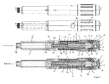
- the drive and metering device comprises according to the first to fourth embodiments, a sleeve-shaped housing 4, which has an outer sleeve 4b, which can be grasped by the user with one hand.
- the housing 4 further comprises an inner sleeve 4a, which forms an abutment 4i and is arranged concentrically with the outer sleeve 4b.
- Inner sleeve 4a and outer sleeve 4b are interconnected via an annular web.
- an annular gap is formed, in which a dose indicator element 10, in particular as a dose display drum, d.
- a bearing element 9 and a coupling member 2 which is sleeve-shaped and in particular can also be referred to as a display coupling, are arranged.
- a sleeve-shaped product container receptacle 5 made of a preferably transparent material is arranged, in which a product container 14 is received in the form of a carpule.
- the product container 14 is permanently connected by means of the product container receptacle 5 to the housing 4, so that the drive and metering device forms a disposable injection device, in particular together with the product container receptacle 5 and the product container 14, which is disposed of as a whole after complete emptying of the product container 14.
- the product container 14 has at its distal end a septum 14b, which can be pierced by a needle which can be attached at the distal end of the product container 14 or the product container holder 5.
- a piston 14 a is received, wherein the product to be distributed is arranged between the septum 14 b and the piston 14 a.
- a protective cap (not shown) which is attachable over the product container receptacle 5 and is removed prior to injecting a dose.
- the drive and metering device has a propulsion member 8 and a rotary member 1.
- the advancing member 8 is arranged so that a distal end 8 g act on the piston 14 a, in particular can press against the piston 14 a.
- the rotary member 1 is axially fixed relative to the housing 4 and rotatably disposed about the longitudinal axis L.
- the rotary member 1 and the Driving member 8 are coupled to each other or engage each other so that rotation of the rotary member 1 relative to the housing 4 and / or to the advancing member 8 causes movement of the advancing member 8 along the longitudinal axis L in the distal direction to the displacement of the piston 14 a.
- the rotary member 1 has at its proximal end an enlarged diameter, in particular in the shape of a widened head.
- an external toothing teeth are arranged, which serve as a second and / or fourth coupling structure 1b, as will be described below.
- an annular friction surface reduced in diameter relative to the head which is in contact with an inwardly projecting annular web of the housing 4, for example forming an abutment 4i. Due to the reduced diameter of the annular friction surface of the point of application of the resulting force is moved closer to the longitudinal axis L, whereby the friction torque between the rotary member 1 and housing 4 is reduced.
- the drive and metering device has at least one discharge spring 11; 11a, 11b.
- the at least one discharge spring 11; 11a, 11b is at delivery, i. H. in the delivery state of the drive and metering device so strongly biased that the energy stored in it is sufficient to distribute the product contained in the product container 14 substantially completely, in particular with several individual distributions, between each of which a new dose setting is made.
- the advantage of the at least one prestressed spring 11; 11a, 11b is that the at least one spring 11; 11a, 11b, for example, does not have to be cocked during dose setting, thereby providing the user of the device with a force-saving, e.g. H. easier dose setting is vorappelbar.
- the at least one discharge spring 11; 11a, 11b is formed in the first to third embodiments as a helical or spiral spring, which acts as a compression spring and strives to push apart the abutment 4i and the advancing member 8, d. H. to move the advancing member 8 in the distal direction relative to the housing 4.
- the propulsion member 8 is rotatable relative to the housing 4 and axially displaceable along the longitudinal axis L.
- the rotary member 1 is formed as a threaded rod which forms an external thread 1a and is in threaded engagement with an internal thread of the sleeve-shaped advancing member 8.
- the pitch of the threads of the threaded engagement between the driving member 8 and the rotary member 1 is so great that no self-locking of the threaded engagement occurs, d. h., That the rotary member 1 is rotatable or rotatable relative to the driving member 8 about the longitudinal axis L due to the force acting along the longitudinal axis L axial force of the discharge spring 11.
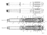
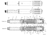
- the at least one spring 11; 11a, 11b is in the third embodiment ( FIG. 3 ) a single spring and in the first and second embodiments ( FIGS. 1 and 2 ) a first spring 11a and a second spring 11b.
- the first spring 11a and the second spring 11b are connected in series.
- the spring 11 is supported with its distal end on an annular web, in particular the shoulder 8g, of the advancing member 8, which firmly connects an outer sleeve and an inner sleeve 8b of the advancing member 8.
- the spring 11 is supported with its proximal end on the annular web formed by the housing 4 and projecting inwards, which forms the abutment 4i.
- the spring 11 is at least partially disposed in the annular gap between the outer sleeve and the inner sleeve 8b of the advancing member 8.
- the inner sleeve 8b of the advancing member 8 has the internal thread 8c for threaded engagement with the rotary member 1.
- a guide is formed by means of at least one longitudinal rib 8a and at least one longitudinal guide 4c, which prevents rotation of the advancing member 8 relative to the housing 4 and axial movement of the advancing member 8 relative to the housing 4 between the inner sleeve 4a and the advancing member 8 and its outer sleeve allowed.
- the longitudinal rib 8a is preferably formed by the outer sleeve of the advancing member 8.
- the advancing member 8 has the inner sleeve 8b, which in this example has at its proximal end the internal thread 8a, which engages in the external thread 1a of the rotary member 1 designed as a threaded rod.
- the annular web, in particular the shoulder 8g, of the advancing member 8 is arranged in the proximal half, in particular in the proximal third of the advancing member 8, relative to the total length of the advancing member 8 measured along the longitudinal axis L.
- the distance measured along the longitudinal axis L between the distal end of the advancing member 8 and the annular web of the advancing member 8 is preferably greater than the distance measured along the longitudinal axis L between the piston 14a and the proximal end of the product container 14 when the piston 14a is in position is in which the maximum distributable from the product container product amount is distributed, d. H. in substantially completely emptied product container. This advantageously prevents the annular web from abutting the proximal end of the product container 14 or at least moving into the product container 14.
- the first spring 11 is supported at its proximal end on the annular web formed by the housing 4 and projecting inwards, which forms the abutment 4a.
- the spring 11 is supported with its distal end on a particular annular, the advancing member 8 preferably surrounding the intermediate member 11c.
- the second spring 11 b is supported with its distal end on an annular web or annular collar, for example in the region of the distal end 8 d of the advancing member 8.
- the second spring 11b is supported with its proximal end on the intermediate member 11c.
- the intermediate member 11c couples the propulsion member 8 and the housing 4 so that the propulsion member 8 is displaceable relative to the housing 4 along the longitudinal axis L and secured against rotation about the longitudinal axis L.
- the intermediate member 11c and the inner sleeve 4a of the housing 4 engage with each other so that the intermediate member 11c is rotationally fixed and axially displaceable with respect to the housing 4.
- the intermediate member 11c and the advancing member 8 engage each other so that the intermediate member 11c is slidable relative to the driving member 8 along the longitudinal axis L and rotatable about the longitudinal axis L.
- the second spring 11b has an outer diameter smaller than the outer diameter of the first spring 11a. This makes it possible to ensure that the region of the advancing member 8 or of the first spring 11b, which is displaced in the product container 14 for the product discharge, has sufficient distance to the inner wall of the product container 14 leading to the piston 14a.
- the proximal end of the second spring 11b is located distally of the distal end of the first spring 11a.
- the intermediate member 11 c is arranged so that it is spaced along the longitudinal axis L of a proximal end of the product container 14 when the out of the product container 14th This is to ensure that the first and the second spring 11a, 11b are involved in the dispensing process until the product is completely dispensed.
- the first spring 11a surrounds the propulsion member 8, wherein the second spring 11b surrounds the propulsion member 8.
- the first spring 11a and the second spring 11b are arranged in the annular gap formed between the driving member 8 and the inner sleeve 4a of the housing 4. This arrangement allows a particularly simple assembly of the drive and metering device.
- the propulsion member 8 surrounds the second spring 11b.
- the first spring 11a is arranged in the annular gap between the inner sleeve 4a and the advancing member 8.
- the second spring 11 b is arranged in the annular gap formed between the rotary member 1 and the driving member 8.
- the sleeve-shaped advancing member 8 has at least one elongate slot 8f extending parallel to the longitudinal axis L, through which the intermediate member 11c engages and in which the intermediate member 11c is displaceable.
- the first spring 11a and the second spring 11b may be supported on the intermediate member 11c.
- the slot 8f can advantageously serve for the rotationally fixed and axially displaceable engagement of the intermediate member 11c with the advancing member 8.
- the rotary member 1 is sleeve-shaped and surrounds the elongated, in particular designed as a threaded rod driving member 8.
- the propulsion member 8 and the rotary member 1 engage each other so that the propulsion member 8 with respect to the rotary member 1 rotatable about the longitudinal axis L and along the longitudinal axis L is displaceable.
- the advancing member 8 has an external thread, which is in a threaded engagement with an internal thread of the housing 4.
- a rotation of the rotary member 1 relative to the housing 4 causes a rotation of the driving member 8, whereby the driving member 8 screwed to the housing 4 along the longitudinal axis L.
- the spring 11 is in the fourth embodiment, a helically wound from a band-shaped material spring acting as a torsion or torsion spring. Such springs are also referred to as clock springs.
- the spring 11 is supported at one end on the rotary member 1 and the other end on the housing 4 or the housing-fixed housing insert, which forms the inner sleeve 4a from.
- the inner sleeve 4a is connected via an annular web to the housing 4 and the outer sleeve 4b, wherein the spring 11 is arranged distally of the annular web.
- the spring 11 is arranged in particular distally of a dose indicator element 10 and / or a bearing element 9.
- the bearing element 9 or / and the dose indicator element 10 are arranged proximally of the annular web.
- the spring 11 is arranged between the annular web, which connects the inner sleeve 4 a to the outer sleeve 4 b, and the annular web, which has the internal thread for threaded engagement with the advancing member 8. This arrangement allows particularly advantageous that the torque generated by the spring 11 is conducted in the shortest possible path during the product discharge in the propulsion member 8.
- the outer diameter of the spring 11 is greater than the inner diameter of the sleeve-shaped portion 4a.
- the spring 11 can move the driving member 8 by a Aus patternhub in the distal direction, which is proportional to the rotational angle of the rotary member 1.
- the drive and metering device further comprises a bearing element 9, which may also be referred to as a display drum bearing element and relative to the housing 4 rotatably but slidably disposed along the longitudinal axis L.
- the bearing element 9 is sleeve-shaped and preferably surrounds the inner sleeve 4 a of the housing 4, wherein in particular the outer sleeve 4 b surrounds the bearing element 9.
- the bearing element 9 is in engagement with the housing 4, in particular the inner sleeve 4a, which allows a longitudinal movement of the bearing element 9 relative to the housing 4, but prevents rotational movement.
- the engagement can be formed by a longitudinal guide 9f between the bearing element 9 and the inner sleeve 4a.
- the bearing element 9 has a thread 9a, in particular an external thread, into which a thread 10e, in particular an internal thread, of the dose indicator element 10 engages. Through this threaded engagement, the display element 10 can be screwed relative to the bearing element 9.
- the illustrated embodiments include a dose setting signal generating mechanism (dispensing click means) and a product dispensing signal generating mechanism (dispensing clipping means) each providing an audible and / or tactile signal upon dose setting or product dispensing.
- the Aus sectiontician's has an annular clicker 15 which is arranged in the actuator 7 and has a locking member which engages in a circumferentially extending internal teeth 7b of the actuator 7 resiliently or elastically yielding .
- the clicker 15 and the coupling member 2 are in a rotation secured about the longitudinal axis L engagement, so that the clicker 15 is rotated by the coupling member 2 when the coupling member 2 is rotated relative to the housing 4 about the longitudinal axis L.
- a rotation of the sleeve-shaped coupling member 2 relative to the housing 4 and / or the actuator 7 causes the locking member of the clicker 15 engages over the internal teeth 7b and thereby generates the acoustic and / or tactile signal.
- the Dosiertician looks has a resiliently formed on the coupling member 2 engaging member, which engages in the external toothing, which forms the second coupling structure 1b.
- the coupling member 2 rotates during dose setting relative to the rotary member 1, whereby the locking member 2c via the second coupling structure 1b snaps and thereby generates the acoustic and / or tactile signal during dose setting.
- the external toothing is designed, in particular the distance between the teeth, that they the setting of discrete dose-proportional angular steps and / or the generation of a slight resistance in the dose setting and / or the generation of the acoustic or tactile signal, such as a hearing and tactile clicks during dose setting
- the dose indicator element 10 is rotatably, but axially displaceably connected to the coupling member 2, in particular in engagement.
- This engagement comprises a longitudinal guide 2a, which causes the dose indicator element 10 to rotate relative to the coupling member 2, but axially displaceable.
- a rotation of the coupling member 2 relative to the bearing member 9 causes due to the rotationally fixed connection between the coupling member 2 and dose indicator member 10 that the dose indicator member 10 is also rotated and due to the Threaded engagement is screwed into the thread 9a on the bearing element 9 along, in particular in addition to the click noise generated due to the locking members.
- the dose indicator element 10 has, over its outer circumference, a dose scale which extends helically in accordance with the pitch of the thread 10e and which comprises a multiplicity of scale values arranged one after the other.
- a dose scale which extends helically in accordance with the pitch of the thread 10e and which comprises a multiplicity of scale values arranged one after the other.
- the scale ranges from 0 to 80 and the dose values are given in 2-step increments.
- the dose indicating element 10 has at its e.g. proximal end has a circumferentially facing and acting abutment surface referred to as a zero dose stop.
- the dose indicator 10 has at its, e.g. opposite to the proximal end, distal end a circumferentially facing and acting stop surface, which is referred to as maximum dose stop.
- the dose indicating element 10 can be screwed back and forth on the bearing element 9 between a zero dose position and a maximum dose position.
- the zero dose stop in cooperation with a zero dose counter-stroke formed by the housing 4, prevents rotation of the dose indicating element 10 in a first rotational direction, namely a direction of rotation that would cause a dose smaller than zero to be set.
- the dose indicator 10 is in the opposite, d. H. rotatable second direction of rotation.
- the maximum dose stop In the maximum dose position, the maximum dose stop, in cooperation with a maximum dose counterpart stopper formed by the bearing member 9, prevents the rotation of the dose indicating element 10 in the second rotational direction which would cause the dose to increase beyond the maximum adjustable value.
- the rotation in the first direction of rotation is possible in the maximum dose position.
- the maximum dose counter-abutment is formed by the bearing element 9, unlike this example, the maximum dose counter-abutment may optionally be formed by the housing 4. Unlike the example shown, the zero dose counter stop can be formed by the bearing element 9.
- the housing 4 has a pointing device 4d in the form of a window, which exposes the scale of the dose indicator element 10.
- a dosing member 3 rotatably but axially fixed in the form of a Dosierknopfs.
- the housing 4 an annular groove 4 g, in which engages in particular an annular shoulder of the dosing member 3.
- the dosing member 3 has over its outer periphery a handle structure 3b, which makes it easier for the user of the device to rotate the dosing member 3 relative to the housing 4.
- In the unactuated state of the device causes a rotation of the dosing member 3, a rotation or screw movement of the dose indicator element 10, whereby the desired dose is adjustable and readable in the pointing device 4d.
- an actuator 7 Disposed on the dosing member 3 is an actuator 7 in the form of an actuating button which is movable relative to the dosing member 3 for actuation of the product dispensing device, in particular along the longitudinal axis L.
- the actuator 7 forms the proximal end of the device and is from the thumb the hand of the user, which surrounds the housing 4, actuated in a simple manner, in particular relative to the housing 4 and / or to the dosing member 3 slidably.
- the coupling member 2 is rotatable and axially fixed relative to the actuator 7, in particular when dissolved Dosierkupplung 2b, 3c.
- the actuator 7 with the coupling member 2 axially fixed but rotatably snapped.
- the drive and metering device further comprises a reset or clutch spring 12 which is tensioned upon actuation, in particular pressing of the actuator 7 and which resets the bearing element 9 and / or the actuator 7 in its unactuated position when the actuator 7 is unactuated.
- An actuation of the actuator 7 causes in addition to its axial displacement also the axial displacement of the bearing element 9 along the longitudinal axis L.
- the spring 12 is supported with its distal end preferably on the dosing member 3 and with its proximal end preferably on the actuator 7 from.
- the spring 12 is preferably a helical or helical spring, which acts as a compression spring.
- the dosing member 3 is rotationally fixed relative to the actuator 7.
- the actuating member 7 engages through an inwardly projecting shoulder of the dosing 3.
- an eighth coupling structure 7a is formed in the form of an external toothing, which by operating the actuator 7 with a formed on the housing 4 seventh coupling structure 4h in the form of an internal toothing, in particular at the proximal end of the housing 4, is coupled in an engagement, whereby the dosing member 3 with respect to the housing 4 is non-rotatable.
- This causes a dose setting, ie a rotation of the dosing member 3 relative to the housing 4 is not possible, but only when the actuator 7 is unconfirmed.
- the seventh and eighth clutch structures 4h, 7a form a fourth clutch 4h, 7a.
- the dosing member 3 forms a sixth coupling structure 3c of the third clutch 2b, 3c, in particular on the inwardly projecting shoulder.
- the sixth coupling structure 3c is rotatably engaged in the case of an unactuated actuating member 7 with a fifth coupling structure 2b of the third clutch 2b, 3c formed as external toothing on the coupling member 2.
- the third clutch 2b, 3c is engaged.
- the third clutch 2b, 3c may also be referred to as Dosierkupplung, which at the dose setting, d. H. engaged with unconfirmed actuator 7 and in the dose distribution, d. H.
- the third clutch 2b, 3 is disengaged when actuated actuator 7, wherein the third clutch 2b, 3 transmits torque in the engaged state and transmits no torque in the disengaged state.
- the third clutch 2b, 3c is disengaged by a displacement of the coupling member 2 relative to the housing 4, in particular due to the actuation of the actuator 7th
- the bearing element 9 has at its proximal end on the inner circumference a first coupling structure 9e, which is formed by an inner toothing arranged over the circumference, which are in engagement with the toothing of the rotary element 1 forming the second coupling structure 1b, in particular when the actuating element 7 is not actuated.
- the first coupling structure 9e and the second coupling structure 1b form a first coupling 1b, 9e.
- the coupling member 2 further has a third coupling structure 2d on an inner circumference, which has an inner toothing arranged over the circumference.
- the third coupling structure 2d is arranged such that upon actuation of the actuating member 7 it engages in rotation with the rotary member 1, in particular with the second coupling structure 1b or alternatively with a fourth coupling structure separate from the second coupling structure 1b but not shown in these examples ,
- the third clutch structure 2b and second or fourth clutch structure 1b form a second clutch 1b, 2d.
- the at least one discharge spring 11; 11a, 11b wherein the rotary member 1 is rotated relative to the housing 4 and due to the engagement of the second coupling structure 1b with the third coupling structure 2d, the coupling member 2 and thus also the dose indicator 10 are rotated relative to the housing 4, whereby the dose indicator 10 screwed back to its zero dose position and the propulsion member 8 is displaced in proportion to the particular circumferentially extending distance between zero dose stop 10c and zero dose counter-stop 4f to a Ausurgihub relative to the housing 4 in the distal direction.
- the rotation of the coupling member 2 relative to the actuator 7 causes the latching members of the clicker 15 via the teeth 7b in particular in dose-proportional angular increments and thereby generate the acoustic and / or tactile signal.
- the drive and metering device has a dose limiter in the form of a ring, a ring segment or a nut, which has a thread on its inner circumference, which engages in a arranged on an outer circumference of the housing 4 thread 4 e, so that the dose limiter relative to the Housing 4 is screwed.
- the dose limiter On the outer circumference, the dose limiter has an engagement member, which engages in a longitudinal guide 3a on the inner circumference of the dosing member 3, so that the dose limiter is rotatable relative to the dosing member 3 but axially displaceable.
- a stop stop is formed, from which the dose limiter is spaced in proportion to the maximum amount of product to be distributed from the product container 14.
- a counter can be formed by the dose limiter, which adds the already distributed individual doses and the currently set dose and accordingly closer to the stop stop of Dosing member 3 or the housing 4 approaches.
- a dose increase causes the dose limiter to move toward the stop stop.
- Dose reduction causes the dose limiter to be moved away from the stop stop. If the residual dose indicated in the product container 14 is less than the maximum dose which can be set with the drive and metering device, the dose limiter comes into contact with the stop stop, so that a rotation of the dosing member 3 relative to the housing 4 in a rotational direction, which would result in an increase in the dose is blocked.
- first clutch 1b, 9e and second clutch 1b, 2d may also be referred to as a discharge clutch.
- the drive and metering device which may also be referred to as an injection device, is shown in its initial or delivery state, in particular before a first use.
- the product dose displayed in the pointing device 4d is 0.
- Actuating the actuator 7 would result in no dose being released.
- the dose limiter has a distance to the stop stop, which is proportional to the amount of product contained in the product container 14 or distributable, such. B. 300 IU
- the coupling member 2 and thus also the dose indicator element 10 are rotated relative to the housing 4.
- the dose indicator element 10 screws along the bearing element 9 due to the threaded engagement of the thread 10e with the thread 9a.
- the distance between the zero dose stop and the zero dose counter stroke is increased in proportion to the dose shown in the pointing device 4d.
- an audible and tactile signal is generated during the rotation due to the latching of the locking members on the teeth 1b.
- a maximum adjustable dose such as 80 I.U., which are then readable in the pointing device 4d, a further dose increase is not possible due to the interaction, in particular the contact of the maximum dose stop with the maximum dose counteracting stop.
- the dose limiter is equivalent to 80 I.U. moved far to the stop stop or moved.
- the actuator 7 is actuated, in particular pressed, ie displaced relative to the housing 4 and the dosing member 3 in the distal direction, whereby the coupling member 2 and the bearing element 9 and the dose indicator 10 relative to the housing 4 in be moved distal direction, in particular against the force of the clutch or reset spring 12th
- Actuation of the actuator 7 causes the second clutch 1b, 2d to engage and disengage the first clutch 1b, 9e so that the rotary member 1 is no longer rotationally fixed with respect to the housing 4 and is rotatable with respect to the clutch member 2 and Dose indicator 10 is rotationally fixed.
- the operation of the actuator 7 further causes the third clutch 2 b, 3 c is disengaged and the fourth clutch 4 h, 7 a is engaged.
- the rotary member 1 is rotationally fixed relative to the dose indicator 10, whereby the rotary member 1 and the dose indicator 10 can rotate together relative to the housing 4.
- the drive and metering device or injection device is disposed of as a whole. It is thus a disposable injection device.
- the drive and metering devices shown herein can also be used in conjunction with reusable injection devices in which a deflated product container 14 is replaced with a new one.
Landscapes
- Health & Medical Sciences (AREA)
- Vascular Medicine (AREA)
- Engineering & Computer Science (AREA)
- Anesthesiology (AREA)
- Biomedical Technology (AREA)
- Heart & Thoracic Surgery (AREA)
- Hematology (AREA)
- Life Sciences & Earth Sciences (AREA)
- Animal Behavior & Ethology (AREA)
- General Health & Medical Sciences (AREA)
- Public Health (AREA)
- Veterinary Medicine (AREA)
- Infusion, Injection, And Reservoir Apparatuses (AREA)
Priority Applications (5)
| Application Number | Priority Date | Filing Date | Title |
|---|---|---|---|
| EP13195951.2A EP2881132B1 (fr) | 2013-12-05 | 2013-12-05 | Dispositif d'injection doté d'un organe de dosage et d'un ressort de versement précontraint |
| EP17172636.7A EP3263159B1 (fr) | 2013-12-05 | 2013-12-05 | Dispositif d'injection doté d'un organe de dosage et d'un ressort de versement précontraint |
| PCT/CH2014/000165 WO2015081453A1 (fr) | 2013-12-05 | 2014-11-14 | Dispositif d'injection doté d'un élément de dosage et d'un ressort d'expulsion précontraint |
| CN201480065901.7A CN105764548B (zh) | 2013-12-05 | 2014-11-14 | 带有配量环节和预紧的放出弹簧的注射装置 |
| US15/173,333 US10596327B2 (en) | 2013-12-05 | 2016-06-03 | Injection device with a dosing member and a pretensioned discharge spring |
Applications Claiming Priority (1)
| Application Number | Priority Date | Filing Date | Title |
|---|---|---|---|
| EP13195951.2A EP2881132B1 (fr) | 2013-12-05 | 2013-12-05 | Dispositif d'injection doté d'un organe de dosage et d'un ressort de versement précontraint |
Related Child Applications (3)
| Application Number | Title | Priority Date | Filing Date |
|---|---|---|---|
| EP17172636.7A Division EP3263159B1 (fr) | 2013-12-05 | 2013-12-05 | Dispositif d'injection doté d'un organe de dosage et d'un ressort de versement précontraint |
| EP17172636.7A Previously-Filed-Application EP3263159B1 (fr) | 2013-12-05 | 2013-12-05 | Dispositif d'injection doté d'un organe de dosage et d'un ressort de versement précontraint |
| EP17172636.7A Division-Into EP3263159B1 (fr) | 2013-12-05 | 2013-12-05 | Dispositif d'injection doté d'un organe de dosage et d'un ressort de versement précontraint |
Publications (2)
| Publication Number | Publication Date |
|---|---|
| EP2881132A1 true EP2881132A1 (fr) | 2015-06-10 |
| EP2881132B1 EP2881132B1 (fr) | 2017-10-18 |
Family
ID=49725049
Family Applications (2)
| Application Number | Title | Priority Date | Filing Date |
|---|---|---|---|
| EP17172636.7A Active EP3263159B1 (fr) | 2013-12-05 | 2013-12-05 | Dispositif d'injection doté d'un organe de dosage et d'un ressort de versement précontraint |
| EP13195951.2A Active EP2881132B1 (fr) | 2013-12-05 | 2013-12-05 | Dispositif d'injection doté d'un organe de dosage et d'un ressort de versement précontraint |
Family Applications Before (1)
| Application Number | Title | Priority Date | Filing Date |
|---|---|---|---|
| EP17172636.7A Active EP3263159B1 (fr) | 2013-12-05 | 2013-12-05 | Dispositif d'injection doté d'un organe de dosage et d'un ressort de versement précontraint |
Country Status (4)
| Country | Link |
|---|---|
| US (1) | US10596327B2 (fr) |
| EP (2) | EP3263159B1 (fr) |
| CN (1) | CN105764548B (fr) |
| WO (1) | WO2015081453A1 (fr) |
Families Citing this family (6)
| Publication number | Priority date | Publication date | Assignee | Title |
|---|---|---|---|---|
| US10512732B2 (en) * | 2013-11-22 | 2019-12-24 | Sanofi-Aventis Deutschland Gmbh | Drug delivery device with dose knob clutch |
| US11464917B2 (en) | 2017-10-30 | 2022-10-11 | Sanofi | Injector device |
| EP3886946A1 (fr) | 2019-06-05 | 2021-10-06 | Regeneron Pharmaceuticals, Inc. | Dispositifs et procédés pour l'administration précise de doses |
| USD921196S1 (en) * | 2019-06-21 | 2021-06-01 | Kaiser Technology Co., Ltd. | Modular micro tool handle |
| JP1691374S (fr) * | 2019-11-01 | 2021-08-02 | ||
| USD1120314S1 (en) | 2022-11-30 | 2026-03-24 | Regeneron Pharmaceuticals, Inc. | Dose delivery device |
Citations (6)
| Publication number | Priority date | Publication date | Assignee | Title |
|---|---|---|---|---|
| WO2001019434A1 (fr) | 1999-09-16 | 2001-03-22 | Novo Nordisk A/S | Limiteur de dosage |
| EP1681070A1 (fr) * | 2005-01-18 | 2006-07-19 | Wockhardt Americas Inc. | Appareils d'injection de médicament de type stylo |
| WO2009141005A1 (fr) * | 2008-05-20 | 2009-11-26 | Tecpharma Licensing Ag | Dispositif d'administration d'un produit injectable comportant une indication de quantité résiduelle |
| WO2010149209A1 (fr) | 2009-06-23 | 2010-12-29 | Tecpharma Licensing Ag | Dispositif d'injection muni d'un mécanisme de dosage pour limiter un réglage de dose |
| EP2644217A1 (fr) * | 2012-03-30 | 2013-10-02 | TecPharma Licensing AG | Dispositif d'injection avec affichage de dose et entraînement par ressort |
| WO2013144020A1 (fr) * | 2012-03-30 | 2013-10-03 | Tecpharma Licensing Ag | Dispositif d'injection comprenant un élément indicateur de dose qui peut se déplacer par rapport à un boîtier |
Family Cites Families (6)
| Publication number | Priority date | Publication date | Assignee | Title |
|---|---|---|---|---|
| DE19822031C2 (de) * | 1998-05-15 | 2000-03-23 | Disetronic Licensing Ag | Autoinjektionsgerät |
| DE102006006796A1 (de) * | 2006-02-14 | 2007-08-16 | Tecpharma Licensing Ag | Überlappende Anzeige |
| EP2129416A1 (fr) * | 2007-03-22 | 2009-12-09 | Tecpharma Licensing AG | Ensemble ressort dans un dispositif d'injection |
| CN101829381B (zh) * | 2010-04-07 | 2015-04-29 | 邓源基 | 一次性可调计量胰岛素注射笔 |
| EP2579920B1 (fr) * | 2010-06-11 | 2019-07-31 | Sanofi-Aventis Deutschland GmbH | Ensemble pour un dispositif d'administration de médicaments et dispositif d'administration de médicaments |
| DK2983765T3 (da) * | 2013-04-10 | 2022-07-18 | Sanofi Sa | Injektionsanordning |
-
2013
- 2013-12-05 EP EP17172636.7A patent/EP3263159B1/fr active Active
- 2013-12-05 EP EP13195951.2A patent/EP2881132B1/fr active Active
-
2014
- 2014-11-14 CN CN201480065901.7A patent/CN105764548B/zh active Active
- 2014-11-14 WO PCT/CH2014/000165 patent/WO2015081453A1/fr not_active Ceased
-
2016
- 2016-06-03 US US15/173,333 patent/US10596327B2/en active Active
Patent Citations (7)
| Publication number | Priority date | Publication date | Assignee | Title |
|---|---|---|---|---|
| WO2001019434A1 (fr) | 1999-09-16 | 2001-03-22 | Novo Nordisk A/S | Limiteur de dosage |
| EP1681070A1 (fr) * | 2005-01-18 | 2006-07-19 | Wockhardt Americas Inc. | Appareils d'injection de médicament de type stylo |
| WO2009141005A1 (fr) * | 2008-05-20 | 2009-11-26 | Tecpharma Licensing Ag | Dispositif d'administration d'un produit injectable comportant une indication de quantité résiduelle |
| WO2010149209A1 (fr) | 2009-06-23 | 2010-12-29 | Tecpharma Licensing Ag | Dispositif d'injection muni d'un mécanisme de dosage pour limiter un réglage de dose |
| EP2644217A1 (fr) * | 2012-03-30 | 2013-10-02 | TecPharma Licensing AG | Dispositif d'injection avec affichage de dose et entraînement par ressort |
| WO2013144020A1 (fr) * | 2012-03-30 | 2013-10-03 | Tecpharma Licensing Ag | Dispositif d'injection comprenant un élément indicateur de dose qui peut se déplacer par rapport à un boîtier |
| WO2013144021A1 (fr) | 2012-03-30 | 2013-10-03 | Tecpharma Licensing Ag | Dispositif d'injection ayant un élément doseur et un ressort d'éjection précontraint |
Also Published As
| Publication number | Publication date |
|---|---|
| CN105764548B (zh) | 2019-12-10 |
| EP3263159B1 (fr) | 2020-07-01 |
| US10596327B2 (en) | 2020-03-24 |
| EP3263159A1 (fr) | 2018-01-03 |
| WO2015081453A1 (fr) | 2015-06-11 |
| CN105764548A (zh) | 2016-07-13 |
| EP2881132B1 (fr) | 2017-10-18 |
| US20160279339A1 (en) | 2016-09-29 |
Similar Documents
| Publication | Publication Date | Title |
|---|---|---|
| EP2830684B1 (fr) | Dispositif d'injection avec affichage de dose et entraînement par ressort | |
| EP2644218B1 (fr) | Dispositif d'injection avec affichage de dose et entraînement par ressort | |
| EP2830685B1 (fr) | Dispositif d'injection avec élément d'affichage de dose déplacable relatif à un boitier. | |
| EP3590569B1 (fr) | Dispositif d'administration dosée d'un produit fluide pouvant être séparé pour le changement de récipient | |
| DE69327464T2 (de) | Wiederverwendbare abgabevorrichtung für pharmazeutische produkte mit einer anzeigevorrichtung für die endstellung | |
| EP3043840B1 (fr) | Dispositif d'injection comportant un bouton d'actionnement dont l'actionnement provoque un mouvement de rotation | |
| DE60204422T2 (de) | Automatische einspritzeinheit mit rücksetzeigenschaft | |
| EP2881131B1 (fr) | Dispositif d'entraînement et de dosage pour un dispositif d'injection doté d'un ressort d'entraînement précontraint | |
| EP2692377B1 (fr) | Dispositif d'injection avec élément d'affichage de dose pour signaler fin d'injection | |
| EP2918298B1 (fr) | Mécanisme de dosage amélioré pour un dispositif d'injection pour l'administration d'un produit | |
| DE102007026560A1 (de) | Verabreichungsvorrichtung mit axial beweglichem Anzeigeglied | |
| EP1525015A1 (fr) | Appareil d'administration a fonction d'amor age | |
| EP1416982A2 (fr) | Dispositif de verrouillage destine a la connexion de sections de boitier d'un appareil d'administration | |
| EP2881132B1 (fr) | Dispositif d'injection doté d'un organe de dosage et d'un ressort de versement précontraint | |
| EP2692376B1 (fr) | Dispositif d'injection avec échelle de dosage en forme d'hélice ou de spirale | |
| EP3419702B1 (fr) | Appareil d'injection avec élément d'actionnement disposé latéralement pour déclencher l'administration d'un produit | |
| CH715854A2 (de) | Verabreichungsvorrichtung mit Kopplungsmechanismus. | |
| WO2011057677A1 (fr) | Dispositif d'administration pourvu d'une protection de surcharge pour le dosage |
Legal Events
| Date | Code | Title | Description |
|---|---|---|---|
| PUAI | Public reference made under article 153(3) epc to a published international application that has entered the european phase |
Free format text: ORIGINAL CODE: 0009012 |
|
| 17P | Request for examination filed |
Effective date: 20131205 |
|
| AK | Designated contracting states |
Kind code of ref document: A1 Designated state(s): AL AT BE BG CH CY CZ DE DK EE ES FI FR GB GR HR HU IE IS IT LI LT LU LV MC MK MT NL NO PL PT RO RS SE SI SK SM TR |
|
| AX | Request for extension of the european patent |
Extension state: BA ME |
|
| R17P | Request for examination filed (corrected) |
Effective date: 20151117 |
|
| GRAP | Despatch of communication of intention to grant a patent |
Free format text: ORIGINAL CODE: EPIDOSNIGR1 |
|
| INTG | Intention to grant announced |
Effective date: 20170316 |
|
| GRAS | Grant fee paid |
Free format text: ORIGINAL CODE: EPIDOSNIGR3 |
|
| GRAJ | Information related to disapproval of communication of intention to grant by the applicant or resumption of examination proceedings by the epo deleted |
Free format text: ORIGINAL CODE: EPIDOSDIGR1 |
|
| GRAL | Information related to payment of fee for publishing/printing deleted |
Free format text: ORIGINAL CODE: EPIDOSDIGR3 |
|
| GRAR | Information related to intention to grant a patent recorded |
Free format text: ORIGINAL CODE: EPIDOSNIGR71 |
|
| INTC | Intention to grant announced (deleted) | ||
| GRAA | (expected) grant |
Free format text: ORIGINAL CODE: 0009210 |
|
| AK | Designated contracting states |
Kind code of ref document: B1 Designated state(s): AL AT BE BG CH CY CZ DE DK EE ES FI FR GB GR HR HU IE IS IT LI LT LU LV MC MK MT NL NO PL PT RO RS SE SI SK SM TR |
|
| INTG | Intention to grant announced |
Effective date: 20170911 |
|
| REG | Reference to a national code |
Ref country code: GB Ref legal event code: FG4D Free format text: NOT ENGLISH |
|
| REG | Reference to a national code |
Ref country code: CH Ref legal event code: EP |
|
| REG | Reference to a national code |
Ref country code: AT Ref legal event code: REF Ref document number: 937396 Country of ref document: AT Kind code of ref document: T Effective date: 20171115 Ref country code: IE Ref legal event code: FG4D Free format text: LANGUAGE OF EP DOCUMENT: GERMAN |
|
| REG | Reference to a national code |
Ref country code: DE Ref legal event code: R096 Ref document number: 502013008586 Country of ref document: DE |
|
| REG | Reference to a national code |
Ref country code: FR Ref legal event code: PLFP Year of fee payment: 5 |
|
| REG | Reference to a national code |
Ref country code: NL Ref legal event code: MP Effective date: 20171018 |
|
| REG | Reference to a national code |
Ref country code: LT Ref legal event code: MG4D |
|
| PG25 | Lapsed in a contracting state [announced via postgrant information from national office to epo] |
Ref country code: NL Free format text: LAPSE BECAUSE OF FAILURE TO SUBMIT A TRANSLATION OF THE DESCRIPTION OR TO PAY THE FEE WITHIN THE PRESCRIBED TIME-LIMIT Effective date: 20171018 |
|
| PG25 | Lapsed in a contracting state [announced via postgrant information from national office to epo] |
Ref country code: ES Free format text: LAPSE BECAUSE OF FAILURE TO SUBMIT A TRANSLATION OF THE DESCRIPTION OR TO PAY THE FEE WITHIN THE PRESCRIBED TIME-LIMIT Effective date: 20171018 Ref country code: FI Free format text: LAPSE BECAUSE OF FAILURE TO SUBMIT A TRANSLATION OF THE DESCRIPTION OR TO PAY THE FEE WITHIN THE PRESCRIBED TIME-LIMIT Effective date: 20171018 Ref country code: LT Free format text: LAPSE BECAUSE OF FAILURE TO SUBMIT A TRANSLATION OF THE DESCRIPTION OR TO PAY THE FEE WITHIN THE PRESCRIBED TIME-LIMIT Effective date: 20171018 Ref country code: NO Free format text: LAPSE BECAUSE OF FAILURE TO SUBMIT A TRANSLATION OF THE DESCRIPTION OR TO PAY THE FEE WITHIN THE PRESCRIBED TIME-LIMIT Effective date: 20180118 Ref country code: SE Free format text: LAPSE BECAUSE OF FAILURE TO SUBMIT A TRANSLATION OF THE DESCRIPTION OR TO PAY THE FEE WITHIN THE PRESCRIBED TIME-LIMIT Effective date: 20171018 |
|
| PG25 | Lapsed in a contracting state [announced via postgrant information from national office to epo] |
Ref country code: BG Free format text: LAPSE BECAUSE OF FAILURE TO SUBMIT A TRANSLATION OF THE DESCRIPTION OR TO PAY THE FEE WITHIN THE PRESCRIBED TIME-LIMIT Effective date: 20180118 Ref country code: GR Free format text: LAPSE BECAUSE OF FAILURE TO SUBMIT A TRANSLATION OF THE DESCRIPTION OR TO PAY THE FEE WITHIN THE PRESCRIBED TIME-LIMIT Effective date: 20180119 Ref country code: IS Free format text: LAPSE BECAUSE OF FAILURE TO SUBMIT A TRANSLATION OF THE DESCRIPTION OR TO PAY THE FEE WITHIN THE PRESCRIBED TIME-LIMIT Effective date: 20180218 Ref country code: LV Free format text: LAPSE BECAUSE OF FAILURE TO SUBMIT A TRANSLATION OF THE DESCRIPTION OR TO PAY THE FEE WITHIN THE PRESCRIBED TIME-LIMIT Effective date: 20171018 Ref country code: HR Free format text: LAPSE BECAUSE OF FAILURE TO SUBMIT A TRANSLATION OF THE DESCRIPTION OR TO PAY THE FEE WITHIN THE PRESCRIBED TIME-LIMIT Effective date: 20171018 Ref country code: RS Free format text: LAPSE BECAUSE OF FAILURE TO SUBMIT A TRANSLATION OF THE DESCRIPTION OR TO PAY THE FEE WITHIN THE PRESCRIBED TIME-LIMIT Effective date: 20171018 |
|
| REG | Reference to a national code |
Ref country code: DE Ref legal event code: R097 Ref document number: 502013008586 Country of ref document: DE |
|
| PG25 | Lapsed in a contracting state [announced via postgrant information from national office to epo] |
Ref country code: EE Free format text: LAPSE BECAUSE OF FAILURE TO SUBMIT A TRANSLATION OF THE DESCRIPTION OR TO PAY THE FEE WITHIN THE PRESCRIBED TIME-LIMIT Effective date: 20171018 Ref country code: CZ Free format text: LAPSE BECAUSE OF FAILURE TO SUBMIT A TRANSLATION OF THE DESCRIPTION OR TO PAY THE FEE WITHIN THE PRESCRIBED TIME-LIMIT Effective date: 20171018 Ref country code: DK Free format text: LAPSE BECAUSE OF FAILURE TO SUBMIT A TRANSLATION OF THE DESCRIPTION OR TO PAY THE FEE WITHIN THE PRESCRIBED TIME-LIMIT Effective date: 20171018 Ref country code: SK Free format text: LAPSE BECAUSE OF FAILURE TO SUBMIT A TRANSLATION OF THE DESCRIPTION OR TO PAY THE FEE WITHIN THE PRESCRIBED TIME-LIMIT Effective date: 20171018 |
|
| PLBE | No opposition filed within time limit |
Free format text: ORIGINAL CODE: 0009261 |
|
| STAA | Information on the status of an ep patent application or granted ep patent |
Free format text: STATUS: NO OPPOSITION FILED WITHIN TIME LIMIT |
|
| PG25 | Lapsed in a contracting state [announced via postgrant information from national office to epo] |
Ref country code: SM Free format text: LAPSE BECAUSE OF FAILURE TO SUBMIT A TRANSLATION OF THE DESCRIPTION OR TO PAY THE FEE WITHIN THE PRESCRIBED TIME-LIMIT Effective date: 20171018 Ref country code: PL Free format text: LAPSE BECAUSE OF FAILURE TO SUBMIT A TRANSLATION OF THE DESCRIPTION OR TO PAY THE FEE WITHIN THE PRESCRIBED TIME-LIMIT Effective date: 20171018 Ref country code: RO Free format text: LAPSE BECAUSE OF FAILURE TO SUBMIT A TRANSLATION OF THE DESCRIPTION OR TO PAY THE FEE WITHIN THE PRESCRIBED TIME-LIMIT Effective date: 20171018 Ref country code: IT Free format text: LAPSE BECAUSE OF FAILURE TO SUBMIT A TRANSLATION OF THE DESCRIPTION OR TO PAY THE FEE WITHIN THE PRESCRIBED TIME-LIMIT Effective date: 20171018 |
|
| REG | Reference to a national code |
Ref country code: IE Ref legal event code: MM4A |
|
| 26N | No opposition filed |
Effective date: 20180719 |
|
| PG25 | Lapsed in a contracting state [announced via postgrant information from national office to epo] |
Ref country code: LU Free format text: LAPSE BECAUSE OF NON-PAYMENT OF DUE FEES Effective date: 20171205 Ref country code: MT Free format text: LAPSE BECAUSE OF FAILURE TO SUBMIT A TRANSLATION OF THE DESCRIPTION OR TO PAY THE FEE WITHIN THE PRESCRIBED TIME-LIMIT Effective date: 20171018 |
|
| REG | Reference to a national code |
Ref country code: BE Ref legal event code: MM Effective date: 20171231 |
|
| PG25 | Lapsed in a contracting state [announced via postgrant information from national office to epo] |
Ref country code: IE Free format text: LAPSE BECAUSE OF NON-PAYMENT OF DUE FEES Effective date: 20171205 |
|
| PG25 | Lapsed in a contracting state [announced via postgrant information from national office to epo] |
Ref country code: SI Free format text: LAPSE BECAUSE OF FAILURE TO SUBMIT A TRANSLATION OF THE DESCRIPTION OR TO PAY THE FEE WITHIN THE PRESCRIBED TIME-LIMIT Effective date: 20171018 Ref country code: BE Free format text: LAPSE BECAUSE OF NON-PAYMENT OF DUE FEES Effective date: 20171231 |
|
| PG25 | Lapsed in a contracting state [announced via postgrant information from national office to epo] |
Ref country code: MC Free format text: LAPSE BECAUSE OF FAILURE TO SUBMIT A TRANSLATION OF THE DESCRIPTION OR TO PAY THE FEE WITHIN THE PRESCRIBED TIME-LIMIT Effective date: 20171018 Ref country code: HU Free format text: LAPSE BECAUSE OF FAILURE TO SUBMIT A TRANSLATION OF THE DESCRIPTION OR TO PAY THE FEE WITHIN THE PRESCRIBED TIME-LIMIT; INVALID AB INITIO Effective date: 20131205 |
|
| PG25 | Lapsed in a contracting state [announced via postgrant information from national office to epo] |
Ref country code: CY Free format text: LAPSE BECAUSE OF FAILURE TO SUBMIT A TRANSLATION OF THE DESCRIPTION OR TO PAY THE FEE WITHIN THE PRESCRIBED TIME-LIMIT Effective date: 20171018 |
|
| PG25 | Lapsed in a contracting state [announced via postgrant information from national office to epo] |
Ref country code: MK Free format text: LAPSE BECAUSE OF FAILURE TO SUBMIT A TRANSLATION OF THE DESCRIPTION OR TO PAY THE FEE WITHIN THE PRESCRIBED TIME-LIMIT Effective date: 20171018 |
|
| REG | Reference to a national code |
Ref country code: AT Ref legal event code: MM01 Ref document number: 937396 Country of ref document: AT Kind code of ref document: T Effective date: 20181205 |
|
| PG25 | Lapsed in a contracting state [announced via postgrant information from national office to epo] |
Ref country code: TR Free format text: LAPSE BECAUSE OF FAILURE TO SUBMIT A TRANSLATION OF THE DESCRIPTION OR TO PAY THE FEE WITHIN THE PRESCRIBED TIME-LIMIT Effective date: 20171018 |
|
| PG25 | Lapsed in a contracting state [announced via postgrant information from national office to epo] |
Ref country code: AT Free format text: LAPSE BECAUSE OF NON-PAYMENT OF DUE FEES Effective date: 20181205 |
|
| PG25 | Lapsed in a contracting state [announced via postgrant information from national office to epo] |
Ref country code: PT Free format text: LAPSE BECAUSE OF FAILURE TO SUBMIT A TRANSLATION OF THE DESCRIPTION OR TO PAY THE FEE WITHIN THE PRESCRIBED TIME-LIMIT Effective date: 20171018 |
|
| PG25 | Lapsed in a contracting state [announced via postgrant information from national office to epo] |
Ref country code: AL Free format text: LAPSE BECAUSE OF FAILURE TO SUBMIT A TRANSLATION OF THE DESCRIPTION OR TO PAY THE FEE WITHIN THE PRESCRIBED TIME-LIMIT Effective date: 20171018 |
|
| REG | Reference to a national code |
Ref country code: CH Ref legal event code: PUE Owner name: YPSOMED AG, CH Free format text: FORMER OWNER: TECPHARMA LICENSING AG, CH |
|
| REG | Reference to a national code |
Ref country code: DE Ref legal event code: R082 Ref document number: 502013008586 Country of ref document: DE Representative=s name: SSM SANDMAIR PATENTANWAELTE RECHTSANWALT PARTN, DE Ref country code: DE Ref legal event code: R081 Ref document number: 502013008586 Country of ref document: DE Owner name: YPSOMED AG, CH Free format text: FORMER OWNER: TECPHARMA LICENSING AG, BURGDORF, CH |
|
| REG | Reference to a national code |
Ref country code: GB Ref legal event code: 732E Free format text: REGISTERED BETWEEN 20210325 AND 20210331 |
|
| REG | Reference to a national code |
Ref country code: CH Ref legal event code: U11 Free format text: ST27 STATUS EVENT CODE: U-0-0-U10-U11 (AS PROVIDED BY THE NATIONAL OFFICE) Effective date: 20260101 |
|
| PGFP | Annual fee paid to national office [announced via postgrant information from national office to epo] |
Ref country code: GB Payment date: 20251218 Year of fee payment: 13 |
|
| PGFP | Annual fee paid to national office [announced via postgrant information from national office to epo] |
Ref country code: FR Payment date: 20251218 Year of fee payment: 13 |
|
| PGFP | Annual fee paid to national office [announced via postgrant information from national office to epo] |
Ref country code: DE Payment date: 20251222 Year of fee payment: 13 |
|
| PGFP | Annual fee paid to national office [announced via postgrant information from national office to epo] |
Ref country code: CH Payment date: 20260101 Year of fee payment: 13 |