EP2881069A1 - Système robotisé chirurgical et instrument chirurgical - Google Patents
Système robotisé chirurgical et instrument chirurgical Download PDFInfo
- Publication number
- EP2881069A1 EP2881069A1 EP14004408.2A EP14004408A EP2881069A1 EP 2881069 A1 EP2881069 A1 EP 2881069A1 EP 14004408 A EP14004408 A EP 14004408A EP 2881069 A1 EP2881069 A1 EP 2881069A1
- Authority
- EP
- European Patent Office
- Prior art keywords
- instrument
- drive
- coupling
- shaft
- drive unit
- Prior art date
- Legal status (The legal status is an assumption and is not a legal conclusion. Google has not performed a legal analysis and makes no representation as to the accuracy of the status listed.)
- Granted
Links
Images


Classifications
-
- A—HUMAN NECESSITIES
- A61—MEDICAL OR VETERINARY SCIENCE; HYGIENE
- A61B—DIAGNOSIS; SURGERY; IDENTIFICATION
- A61B90/00—Instruments, implements or accessories specially adapted for surgery or diagnosis and not covered by any of the groups A61B1/00 - A61B50/00, e.g. for luxation treatment or for protecting wound edges
-
- A—HUMAN NECESSITIES
- A61—MEDICAL OR VETERINARY SCIENCE; HYGIENE
- A61B—DIAGNOSIS; SURGERY; IDENTIFICATION
- A61B34/00—Computer-aided surgery; Manipulators or robots specially adapted for use in surgery
- A61B34/30—Surgical robots
-
- A—HUMAN NECESSITIES
- A61—MEDICAL OR VETERINARY SCIENCE; HYGIENE
- A61B—DIAGNOSIS; SURGERY; IDENTIFICATION
- A61B34/00—Computer-aided surgery; Manipulators or robots specially adapted for use in surgery
- A61B34/70—Manipulators specially adapted for use in surgery
- A61B34/71—Manipulators operated by drive cable mechanisms
-
- A—HUMAN NECESSITIES
- A61—MEDICAL OR VETERINARY SCIENCE; HYGIENE
- A61B—DIAGNOSIS; SURGERY; IDENTIFICATION
- A61B46/00—Surgical drapes
- A61B46/10—Surgical drapes specially adapted for instruments, e.g. microscopes
-
- A—HUMAN NECESSITIES
- A61—MEDICAL OR VETERINARY SCIENCE; HYGIENE
- A61B—DIAGNOSIS; SURGERY; IDENTIFICATION
- A61B50/00—Containers, covers, furniture or holders specially adapted for surgical or diagnostic appliances or instruments, e.g. sterile covers
-
- B—PERFORMING OPERATIONS; TRANSPORTING
- B25—HAND TOOLS; PORTABLE POWER-DRIVEN TOOLS; MANIPULATORS
- B25J—MANIPULATORS; CHAMBERS PROVIDED WITH MANIPULATION DEVICES
- B25J19/00—Accessories fitted to manipulators, e.g. for monitoring, for viewing; Safety devices combined with or specially adapted for use in connection with manipulators
- B25J19/0075—Means for protecting the manipulator from its environment or vice versa
-
- G—PHYSICS
- G01—MEASURING; TESTING
- G01D—MEASURING NOT SPECIALLY ADAPTED FOR A SPECIFIC VARIABLE; ARRANGEMENTS FOR MEASURING TWO OR MORE VARIABLES NOT COVERED IN A SINGLE OTHER SUBCLASS; TARIFF METERING APPARATUS; MEASURING OR TESTING NOT OTHERWISE PROVIDED FOR
- G01D5/00—Mechanical means for transferring the output of a sensing member; Means for converting the output of a sensing member to another variable where the form or nature of the sensing member does not constrain the means for converting; Transducers not specially adapted for a specific variable
- G01D5/54—Mechanical means for transferring the output of a sensing member; Means for converting the output of a sensing member to another variable where the form or nature of the sensing member does not constrain the means for converting; Transducers not specially adapted for a specific variable using means specified in two or more of groups G01D5/02, G01D5/12, G01D5/26, G01D5/42, and G01D5/48
-
- A—HUMAN NECESSITIES
- A61—MEDICAL OR VETERINARY SCIENCE; HYGIENE
- A61B—DIAGNOSIS; SURGERY; IDENTIFICATION
- A61B17/00—Surgical instruments, devices or methods
- A61B2017/00477—Coupling
-
- A—HUMAN NECESSITIES
- A61—MEDICAL OR VETERINARY SCIENCE; HYGIENE
- A61B—DIAGNOSIS; SURGERY; IDENTIFICATION
- A61B17/00—Surgical instruments, devices or methods
- A61B2017/00831—Material properties
- A61B2017/00876—Material properties magnetic
-
- A—HUMAN NECESSITIES
- A61—MEDICAL OR VETERINARY SCIENCE; HYGIENE
- A61B—DIAGNOSIS; SURGERY; IDENTIFICATION
- A61B90/00—Instruments, implements or accessories specially adapted for surgery or diagnosis and not covered by any of the groups A61B1/00 - A61B50/00, e.g. for luxation treatment or for protecting wound edges
- A61B90/06—Measuring instruments not otherwise provided for
- A61B2090/067—Measuring instruments not otherwise provided for for measuring angles
-
- A—HUMAN NECESSITIES
- A61—MEDICAL OR VETERINARY SCIENCE; HYGIENE
- A61B—DIAGNOSIS; SURGERY; IDENTIFICATION
- A61B90/00—Instruments, implements or accessories specially adapted for surgery or diagnosis and not covered by any of the groups A61B1/00 - A61B50/00, e.g. for luxation treatment or for protecting wound edges
- A61B90/08—Accessories or related features not otherwise provided for
- A61B2090/0813—Accessories designed for easy sterilising, i.e. re-usable
Definitions
- An instrument assembly is configured accordingly for attachment to a robot or designed as a robot-guided instrument assembly. It comprises a drive unit, an instrument and an instrument interface according to one of the subsequently explained aspects of the present invention.
- One or more drive shafts are designed as hollow shafts in one embodiment.
- the drive unit has one or more drive shafts, which are each arranged concentrically or coaxially in a surrounding hollow drive shaft, in particular are mounted.
- coupled drive shafts of drive unit and instrument are aligned with each other.
- the drive shaft (s) is coaxial, in particular aligned or offset parallel to the instrument shaft.
- a radially compact design can be achieved.
- the drive shaft (s) are (are) angled, in particular at right angles, to the instrument shaft.
- the drive unit can be arranged at an angle, in particular at right angles, to the instrument shaft.
- the instrument has an instrument-side conversion gear for converting a rotation of one or more drive shafts into a corresponding translation of one or more pulling and / or pushing means.
- a traction means may in particular comprise one or more, in particular opposite, rope, belt or belt trumps, a pulling and / or pushing means one or more, in particular counter-rotating, pulling and / or push rods.
- a slotted guide comprises a sliding sleeve which is mounted so as to be non-rotatable relative to the instrument shaft and axially displaceable, in particular on the instrument shaft or a surrounding drive hollow shaft.
- a sliding sleeve and the drive shaft is a, in particular inclined towards the axial direction, gate or groove formed in which a fitting element, in particular a feather key, is positively guided by the other of the sliding sleeve and the drive shaft. In this way, a rotation of the drive shaft is converted into an axial translation of the sliding sleeve, which can thus actuate in particular a pulling and / or pushing means.
- the conversion gear is arranged in a drive unit facing or proximal half of the instrument shaft. In another embodiment, the conversion gear is arranged in a drive unit facing away from or distal half of the instrument shaft.
- the actuation can advantageously be transmitted over a large area of the instrument shaft by the pulling and / or pushing means or by the drive shafts.
- the drive unit which can be difficult to sterilize due to abrasion, lubricants, temperature and / or moisture-sensitive components or the like, are sterile shielded against the operating environment, the actuation by or via the interface in the, advantageously simple sterilizable, instrument is transferred.
- the arrangement of the intermediate elements preferably corresponds to the arrangement of the drive shafts or their coupling parts.
- the drive shafts of drive unit and / or instrument concentric, so in particular the intermediate elements are arranged concentrically to each other, preferably, as explained above, each one, in particular annular, inner intermediate element, concentrically arranged in an outer annular intermediate element, in particular is stored.
- the intermediate elements are mounted sealed, for example by bearing rings having labyrinth seals or the like.
- the friction or form-fitting contact surfaces may be conical in one embodiment.
- a self-centering and / or, in particular in combination with axially displaceable, preferably prestressed, coupling parts a compensation of an axial tolerance can be achieved.
- the internal passage has a blind plug and a closing ring.
- the blind plug is attached to one end of the internal passage, closes it and covers a peripheral region of the internal passage.
- the blind plug can then be pulled by the drive unit, so that it can escape through an outlet opening of the shell from this and can be removed.
- the closing ring can be fixed to the peripheral portion of the internal passage, which has been exposed by removing the blanking plug, and also close the outlet opening of the shell.
- the instrument module has an instrument shaft which can be inserted into a patient with an end effector, the instrument part which can be detachably connected therewith has a drive for actuating the end effector.
- the instrument module may also include a drive for actuating an end effector of an instrument shaft of the instrument part insertable into a patient.
- the sterile barrier has a coupling piece for magnetically coupling a counter element to a coupling element.
- the coupling piece can be connected by means of a seal movable with the remaining barrier, in particular a film, or fixedly connected to this, in particular integrally formed. This can improve mechanical transmission of forces across the barrier.
- the coupling piece has a magnetically conductive material to improve the magnetic coupling.
- the coupling or counter element is mounted with play in a guide of the instrument module or part. In this way, the coupling or counter element during coupling can compensate for a certain lateral offset.
- coupling and counter-element are tappet or wave-like and coupled to each other at the butt end, wherein the magnet assembly pulls coupling and counter-element in the direction of their, preferably aligned, longitudinal extension against each other to transmit tensile forces or torques.
- Coupling and counter element can be positively coupled or coupled to one another in one embodiment, in particular by a toothing, preferably a Hirth or Stirnradvertechnikung. If a sterile barrier is arranged between the coupling element and the counterelement arrangement, the coupling element and the counter element (arrangement) can be positively coupled or coupled in one embodiment to a coupling piece, which is preferably rotatably mounted in the barrier.
- the different orientations may equally be geometrically indeterminate or free, for example, by activating an electromagnet in a coupling element and fixing a ferromagnetic region of a counter element whose flat end side contacts the flat end face of the coupling element in any orientation in this orientation.
- the instrument module has in one embodiment an angle sensor for detecting an angular position of the coupled counter element arrangement , in particular a transmitter, to, in particular, in one or more counter-elements on.
- the angle sensor may have a plurality of individual sensors for detecting each of an angular position of a coupled counter-element.
- the or the Counter-elements of the counter-element arrangement accordingly each have rotationally fixed transmitters which are set up to be detected by the angle sensor of the instrument module, in particular an individual sensor.
- a surgical instrument includes a plurality of instrument parts that may be selectively coupled to the instrument module, the counterpart element assemblies of the different instrument parts having differently coded transmitters configured to be detected by the angle sensor of the instrument module, the angle sensor in addition thereto is set up to detect the coding of the transmitter and so identify the attached instrument part.
- the functionalities, on the one hand to determine the orientation of the counter element arrangement, and on the other hand to identify the coupled instrument part can be implemented by the same transmitter and angle sensors.
- a permanent magnet can equally serve as a transmitter for detecting the angular position and for magnetic coupling in one embodiment.
- a fifth embodiment relates to an instrument assembly according to one of the embodiments two to four, wherein a coupling part of a drive shaft of the drive unit and a coupling part of a drive shaft of the instrument are magnetically coupled together.
- a ninth embodiment relates to a drive unit according to one of the embodiments six to eight, wherein the coupling part axially displaceable, in particular biased, is arranged on the drive shaft.
- An eighteenth embodiment relates to a casing having a hose-like internal passage for passing through a hollow shaft of a robot or a drive unit according to any of the six to nine embodiments and through an outlet opening of the casing, the internal feedthrough having a blind plug and a closure ring for attachment to a peripheral region of the internal feedthrough which is released by removing the blind plug.
- a twenty-first embodiment relates to an instrument module according to the preceding embodiment, wherein the coupling element for the actuation of the end effector is translationally and / or rotationally movable.
- a twenty-sixth embodiment relates to an instrument module according to the preceding embodiment, wherein it has a drive for actuating the coupling element arrangement or an instrument shaft insertable into a patient with an end effector, which can be actuated by the coupling element arrangement.
- a twenty-eighth embodiment relates to an instrument part having a counter-element arrangement with at least one counter-element for coupling a coupling element of the coupling element arrangement of an instrument module according to one of the preceding embodiments, wherein the counter-element has a magnetically loadable region for magnetically coupling the coupling element and / or a rotationally fixed transmitter for detection by the angle sensor of the instrument module.
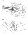
- the instrument arrangement comprises an instrument 1, a drive unit 2 connected thereto, and an instrument interface with a sterile sheath 5 arranged between the drive unit and the instrument.
- the arranged on the drive shafts 10, 13 and 15 coupling parts 31, 32, 33 are each rotatably connected to a shaft, but axially displaceably connected, for example by a tooth or Polygonwellenprofil.
- axial biasing force for example by springs acting on the drive-side coupling parts are applied.
- a possible axial offset between the drive and instrument side shaft sections is compensated.
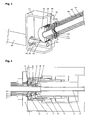
- spur gears 203, 204, 205 are applied to the proximal coupling parts of the instrument-side hollow shafts 16, 17 and 18, which are fixedly connected to the respective hollow shaft.
- the intermediate sleeves 206, 207, 208 are connected to each other and to the sterile barrier 5 by the retaining rings 209, 210, 211.
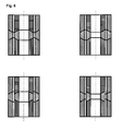
- All magnet rings 200 to 205 are magnetized sector by sector and aligned with, preferably small, axial distance or air gap to each other in order to transmit the highest possible drive torque can.
- the height of the transmittable torque depends not only on the air gap but also on the magnetic field strength and the number of magnetic sectors.
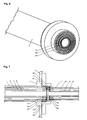
- Fig. 9 shows the magnetic coupling with sterile barrier in a section.
- the magnetic rings are aligned with minimal axial distance from each other in order to transmit the highest possible drive torque can.
- An advantageous feature of this coupling principle is the simple design of the sterile sheath 5. Due to the small axial air gap of the magnetic coupling, a simple foil can be used and does not require a special molded part.
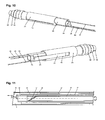
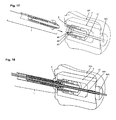
- the coupling of the drive shafts to the sliding sleeves is carried out with a groove guide whose operation is exemplary with respect to the inner hollow shaft 18 and Fig. 11 will be explained, which shows an enlarged section.
- a helical groove 37 is introduced.
- a pin 38 which is fixed to the sliding sleeve 25, engages positively in the helical groove 37 a.
- a rotation of the hollow shaft 18 leads to a displacement of the sleeve 25 along the shaft axis and thus also to an adjusting movement of the pulling and / or pushing means 26.
- the pulling and / or pushing means 26th 39 and 40 which transmit the drive movement to the instrument degrees of freedom and an end effector at the distal end of the instrument shaft 3, respectively.
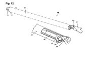
- Fig. 19 shows a part of an instrument of an instrument assembly according to another embodiment of the present invention, which is particularly suitable for flexible additional instruments.
- the auxiliary instrument 507 is not introduced by the drive unit 2, but by a bent pipe section 506, which is arranged on the instrument shaft 505 immediately before the drive unit 2 or instrument interface.
- the sterile sheath 501 can be easier be designed because the additional instrument 507 is not guided from the rear by the drive unit.
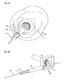
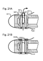
- the internal passage 27 is at its end opposite the blind plug 502 or closing ring 503 (bottom in FIG Fig. 21A, 21B ) turn on the shell 501, for example, as described above with respect to the intermediate elements of the instrument interface.
- the end ring is formed in two parts, wherein a portion 503A of the end ring fastened to the peripheral region of the internal leadthrough is rotatably mounted on a part 503B of the end ring attached to the outlet opening of the shell.
- the internal passage 27 is mounted as a whole rotatably on the shell 501 and can be rotated in particular with a moving through the hollow shaft additional instrument.
- the instrument part comprises a patient-insertable instrument shaft 22 with an end effector (not shown), the instrument module a drive for actuating the end effector, and an electromechanical interface for attachment to a robot (not shown).
- each magnet arrangement has a permanent magnet 30 which is opposite to the electromagnet 31 and whose magnetic field is compensated, at least essentially, by the energized electromagnet 31 in an end-side coupling region of the plunger and the counter-plunger.
- the permanent magnet 30 can be omitted in order to provide by selectively energizing the electromagnet 31 conversely a normally open coupling between coupling and counter element: as long as the solenoid 31 is energized, it couples the magnetically acted upon area 21 of the counter-ram 20th reliable to the magnetically conductive region 11 of the plunger 10.
- the instrument part 2 can be removed from the drive module 1.
- the optional sterile barrier 40 includes a rigid coupling piece 41 of a magnetically conductive material to enhance mechanical power transmission and magnetic coupling.
- the optional sterile barrier may also be film-like as in Fig. 22 be formed or the optional barrier of the execution of Fig. 22 have such a coupling piece.
- Fig. 23 a component made of a non-magnetic material. This can, as in the execution of the Fig. 22 , be designed as potting compound and is therefore denoted by the same reference numeral.
- the component 13 may be a molded part, which is attached to the magnetically conductive region 11 and acts as a stop for the displaceable permanent magnet 30.
- Fig. 24 shows a part of a minimally invasive surgical instrument according to another embodiment of the present invention in Fig. 22, 23 corresponding representation.
- Corresponding elements are again denoted by identical reference numerals, so that reference is made to the rest of the description and subsequently only to the differences from the execution of Fig. 22, 23 will be received.
- the magnet arrangement and the magnetically conductive areas not shown may in particular be formed as in Fig. 22 or 23 illustrated or explained with reference thereto.
- Fig. 24 In the execution of Fig. 24 are plunger 10 and counter-ram 20 in addition to the magnetic coupling positively connected or connected.
- the plunger 10 engages bolt-like in a sleeve or socket portion of the counter-ram 20, when coupling and counter element are coupled together.
- coupling and counter element are perpendicular to their in Fig. 24 vertical longitudinal extent, ie horizontally in the plane or perpendicular to this, positively fixed, the magnetic coupling determines them non-positively in the direction of their longitudinal extent.
- the instrument module 1 in the embodiments of Fig. 25, 26th a non-contact angle sensor in the form of a magnetic encoder for detecting the angular position of the coupled drive shaft 20 relative to the housing or pivot bearing 12 of the instrument module 1auf.
- the drive shaft 20 accordingly has a non-rotatable transmitter in the form of a permanent bar magnet 51, which is adapted to be detected by the angle sensor 50.
- the north-south axis of the bar magnet 51 is oriented perpendicular to the axis of rotation of the drive shaft 20.
- FIGS. 1 to 21 1, 100, 101, 400 instrument 2, 102 drive unit 4 flange 3, 103, 505 instrument shaft 5, 105, 501 (sterile) sheath 6, 104 casing 7, 8, 9 electric motor 11, 12, 14, 28, 29, 30 depository 19, 20, 21, 206, 207, 208 intermediate element 22 conversion gear 23, 24, 25, 37, 38, 200, 201, 202, 406, 407 Sliding sleeve (sliding guide) 26, 39, 40 Push / pull means 31-36, 200-205, 300-305 Spur toothing (coupling part) 27, 115 (sterile) guide tube 37 helical 38 pen 41, 42, 43 Slot guide 10, 13, 15, 16, 17, 18, 106, 107, 108, 109, 110, 111, 404, 405, 406 drive shaft 402 tool kinematics 403 end effector 408, 409 coupling rod 100 instrument-side conversion gear 112, 113, 114 cables 115 guide tube 116, 117, 118 Coupling intermediate segment 209, 210, 211
Landscapes
- Health & Medical Sciences (AREA)
- Engineering & Computer Science (AREA)
- Surgery (AREA)
- Life Sciences & Earth Sciences (AREA)
- Animal Behavior & Ethology (AREA)
- Veterinary Medicine (AREA)
- Biomedical Technology (AREA)
- Heart & Thoracic Surgery (AREA)
- Medical Informatics (AREA)
- Molecular Biology (AREA)
- Public Health (AREA)
- General Health & Medical Sciences (AREA)
- Robotics (AREA)
- Nuclear Medicine, Radiotherapy & Molecular Imaging (AREA)
- Mechanical Engineering (AREA)
- Physics & Mathematics (AREA)
- General Physics & Mathematics (AREA)
- Oral & Maxillofacial Surgery (AREA)
- Pathology (AREA)
- Manipulator (AREA)
- Surgical Instruments (AREA)
Applications Claiming Priority (4)
| Application Number | Priority Date | Filing Date | Title |
|---|---|---|---|
| DE102012008537.0A DE102012008537B4 (de) | 2012-04-27 | 2012-04-27 | Chirurgierobotersystem |
| DE102013004591.6A DE102013004591A1 (de) | 2013-03-15 | 2013-03-15 | Chirurgisches Instrument |
| EP13719025.2A EP2841001B1 (fr) | 2012-04-27 | 2013-04-25 | Module d'instrument pour un instrument chirurgical |
| PCT/EP2013/001253 WO2013159933A1 (fr) | 2012-04-27 | 2013-04-25 | Système de robot chirurgical et instrument chirurgical |
Related Parent Applications (2)
| Application Number | Title | Priority Date | Filing Date |
|---|---|---|---|
| EP13719025.2A Division-Into EP2841001B1 (fr) | 2012-04-27 | 2013-04-25 | Module d'instrument pour un instrument chirurgical |
| EP13719025.2A Division EP2841001B1 (fr) | 2012-04-27 | 2013-04-25 | Module d'instrument pour un instrument chirurgical |
Publications (2)
| Publication Number | Publication Date |
|---|---|
| EP2881069A1 true EP2881069A1 (fr) | 2015-06-10 |
| EP2881069B1 EP2881069B1 (fr) | 2020-03-11 |
Family
ID=48190908
Family Applications (4)
| Application Number | Title | Priority Date | Filing Date |
|---|---|---|---|
| EP13719025.2A Active EP2841001B1 (fr) | 2012-04-27 | 2013-04-25 | Module d'instrument pour un instrument chirurgical |
| EP14004409.0A Active EP2881070B1 (fr) | 2012-04-27 | 2013-04-25 | Système robotisé chirurgical et instrument chirurgical |
| EP14004407.4A Active EP2881068B1 (fr) | 2012-04-27 | 2013-04-25 | Système robotisé chirurgical et instrument chirurgical |
| EP14004408.2A Active EP2881069B1 (fr) | 2012-04-27 | 2013-04-25 | Système robotisé chirurgical et instrument chirurgical |
Family Applications Before (3)
| Application Number | Title | Priority Date | Filing Date |
|---|---|---|---|
| EP13719025.2A Active EP2841001B1 (fr) | 2012-04-27 | 2013-04-25 | Module d'instrument pour un instrument chirurgical |
| EP14004409.0A Active EP2881070B1 (fr) | 2012-04-27 | 2013-04-25 | Système robotisé chirurgical et instrument chirurgical |
| EP14004407.4A Active EP2881068B1 (fr) | 2012-04-27 | 2013-04-25 | Système robotisé chirurgical et instrument chirurgical |
Country Status (5)
| Country | Link |
|---|---|
| US (5) | US20150164593A1 (fr) |
| EP (4) | EP2841001B1 (fr) |
| KR (4) | KR101687088B1 (fr) |
| CN (4) | CN104363854B (fr) |
| WO (1) | WO2013159933A1 (fr) |
Families Citing this family (89)
| Publication number | Priority date | Publication date | Assignee | Title |
|---|---|---|---|---|
| WO2013106822A1 (fr) | 2012-01-12 | 2013-07-18 | Johnson Jed K | Echafaudages en nanofibres pour structures biologiques |
| EP2841001B1 (fr) | 2012-04-27 | 2019-01-02 | KUKA Deutschland GmbH | Module d'instrument pour un instrument chirurgical |
| US20140263541A1 (en) * | 2013-03-14 | 2014-09-18 | Ethicon Endo-Surgery, Inc. | Articulatable surgical instrument comprising an articulation lock |
| US9713503B2 (en) * | 2013-12-04 | 2017-07-25 | Novartis Ag | Surgical utility connector |
| WO2015116282A1 (fr) | 2014-01-31 | 2015-08-06 | Covidien Lp | Interfaces pour systèmes chirurgicaux |
| EP3137010B1 (fr) | 2014-04-29 | 2019-09-25 | Covidien LP | Instruments chirurgicaux, unités d'entraînement d'instrument et leurs ensembles chirurgicaux |
| DE102014107071A1 (de) * | 2014-05-20 | 2015-11-26 | Fraunhofer-Gesellschaft zur Förderung der angewandten Forschung e.V. | Gelenkanordnung mit zumindest einer angetriebenen Achse |
| DE102014009892B4 (de) * | 2014-07-04 | 2018-05-30 | gomtec GmbH | Antriebseinheit mit magnetischer Schnittstelle |
| WO2016057989A2 (fr) * | 2014-10-10 | 2016-04-14 | Transenterix, Inc. | Système chirurgical électromécanique |
| DE102014116103A1 (de) * | 2014-11-05 | 2016-05-12 | Aktormed Gmbh | Operations-Assistenz-System |
| JP6860490B2 (ja) * | 2015-02-20 | 2021-04-14 | ストライカー・コーポレイション | 滅菌バリアアセンブリ、取付システム、及び外科用構成部品を連結する方法 |
| GB2538326B (en) * | 2015-05-07 | 2019-06-05 | Cmr Surgical Ltd | A surgical drape for transferring drive |
| WO2016205481A1 (fr) * | 2015-06-19 | 2016-12-22 | Covidien Lp | Ensembles chirurgicaux robotiques |
| KR101714733B1 (ko) | 2015-08-13 | 2017-03-09 | 한국기계연구원 | 로봇용 로딩유닛의 탈부착장치, 이를 이용한 로봇 및 로봇의 제어방법 |
| CN113229942B (zh) | 2015-09-09 | 2024-11-12 | 奥瑞斯健康公司 | 手术器械装置操纵器 |
| CN108024834A (zh) * | 2015-09-25 | 2018-05-11 | 柯惠Lp公司 | 机器人手术系统的弹性手术接口 |
| US10512466B2 (en) * | 2015-11-05 | 2019-12-24 | Covidien Lp | Adapter assembly for surgical device |
| US10779900B2 (en) * | 2015-12-29 | 2020-09-22 | Covidien Lp | Robotic surgical systems and instrument drive assemblies |
| EP3416582A4 (fr) | 2016-02-16 | 2019-11-06 | Covidien LP | Ensembles chirurgicaux robotiques et support d'instrument chirurgical associé |
| US12426970B2 (en) | 2016-02-16 | 2025-09-30 | Covidien Lp | Robotic surgical assemblies |
| CN108697478A (zh) * | 2016-03-04 | 2018-10-23 | 柯惠Lp公司 | 电动机械手术系统和其机器人手术器械 |
| KR102429815B1 (ko) | 2016-04-14 | 2022-08-08 | 트랜스엔테릭스 서지컬, 인크. | 선형 구동식 기기 롤을 포함하는 전기기계 수술 시스템 |
| US10799239B2 (en) * | 2016-05-09 | 2020-10-13 | Covidien Lp | Adapter assembly with pulley system and worm gear drive for interconnecting electromechanical surgical devices and surgical end effectors |
| US11045265B2 (en) | 2016-05-26 | 2021-06-29 | Covidien Lp | Robotic surgical assemblies and instrument drive units thereof |
| CN109152613A (zh) * | 2016-05-26 | 2019-01-04 | 柯惠Lp公司 | 与机器人手术系统一起使用的插管组件 |
| WO2017205576A1 (fr) | 2016-05-26 | 2017-11-30 | Covidien Lp | Unité de commande d'instruments |
| US11272992B2 (en) | 2016-06-03 | 2022-03-15 | Covidien Lp | Robotic surgical assemblies and instrument drive units thereof |
| KR101898092B1 (ko) * | 2016-06-17 | 2018-09-12 | 주식회사 뉴로메카 | 다자유도 로봇의 말단 제어를 위한 콘트롤러, 상기 콘트롤러를 이용한 다자유도 로봇 제어방법 및 이에 의해 동작하는 로봇 |
| GB2552541B (en) * | 2016-07-29 | 2021-09-01 | Cmr Surgical Ltd | Drive transfer |
| US10687904B2 (en) | 2016-08-16 | 2020-06-23 | Ethicon Llc | Robotics tool exchange |
| US10736702B2 (en) * | 2016-08-16 | 2020-08-11 | Ethicon Llc | Activating and rotating surgical end effectors |
| EP3559929A1 (fr) * | 2016-10-10 | 2019-10-30 | Generic Robotics Limited | Simulateur pour tâches manuelles |
| JP6812348B2 (ja) * | 2016-10-21 | 2021-01-13 | オリンパス株式会社 | 処置具用回転機構 |
| US11259881B2 (en) * | 2016-11-03 | 2022-03-01 | Verb Surgical Inc. | Tool driver with reaction torque sensor for use in robotic surgery |
| US10588704B2 (en) * | 2016-12-09 | 2020-03-17 | Ethicon Llc | Surgical tool and robotic surgical system interfaces |
| US10149727B2 (en) | 2016-12-09 | 2018-12-11 | Ethicon Llc | Surgical tool and robotic surgical system interfaces |
| US10433920B2 (en) | 2016-12-09 | 2019-10-08 | Ethicon Llc | Surgical tool and robotic surgical system interfaces |
| GB2552855B (en) * | 2017-01-31 | 2019-02-13 | Cmr Surgical Ltd | Surgical instrument engagement detection |
| US10376276B2 (en) * | 2017-02-02 | 2019-08-13 | Ethicon Llc | Calibration of a robotic surgical tool |
| US11065069B2 (en) | 2017-05-10 | 2021-07-20 | Mako Surgical Corp. | Robotic spine surgery system and methods |
| US11033341B2 (en) | 2017-05-10 | 2021-06-15 | Mako Surgical Corp. | Robotic spine surgery system and methods |
| US11717361B2 (en) * | 2017-05-24 | 2023-08-08 | Covidien Lp | Electrosurgical robotic system having tool presence detection |
| CN107320193B (zh) * | 2017-07-31 | 2023-06-30 | 成都博恩思医学机器人有限公司 | 连接组件、手术机器人的手术器械及手术机器人 |
| US10624708B2 (en) * | 2017-10-26 | 2020-04-21 | Ethicon Llc | Auto cable tensioning system |
| CN111405878A (zh) * | 2017-11-29 | 2020-07-10 | 柯惠Lp公司 | 机器人手术系统、器械驱动组件以及驱动组件 |
| WO2019135940A1 (fr) | 2018-01-04 | 2019-07-11 | Covidien Lp | Systèmes chirurgicaux robotiques et ensembles d'entraînement d'instrument |
| EP3737328B1 (fr) * | 2018-01-09 | 2025-04-30 | Covidien LP | Module d'interface stérile pour ensembles chirurgicaux robotisés |
| AU2019242611A1 (en) * | 2018-03-29 | 2020-08-20 | Covidien Lp | Robotic surgical systems and instrument drive assemblies |
| CN110559078B (zh) * | 2018-06-05 | 2021-03-30 | 杭州术创机器人有限公司 | 一种用于微创手术系统的套管固定组件 |
| CN109125897B (zh) * | 2018-08-13 | 2021-04-06 | 张宪英 | 一种自助式口腔上药装置 |
| WO2020060789A1 (fr) * | 2018-09-17 | 2020-03-26 | Covidien Lp | Systèmes robotiques chirurgicaux |
| EP3852667A4 (fr) * | 2018-09-17 | 2022-06-15 | Covidien LP | Systèmes robotisés chirurgicaux |
| CN112702971B (zh) * | 2018-09-17 | 2025-02-07 | 柯惠Lp公司 | 手术机器人系统 |
| CN109029591B (zh) * | 2018-10-17 | 2024-02-09 | 辽宁工业大学 | 一种电动微耕机研发实验装置及方法 |
| CN114269280B (zh) * | 2019-08-28 | 2026-01-27 | 柯惠Lp公司 | 用于机器人手术组合件的无菌接口模块 |
| CN112957127B (zh) | 2019-08-30 | 2022-06-17 | 上海微创医疗机器人(集团)股份有限公司 | 传动、驱动、无菌、器械盒组件与手术器械系统、机器人 |
| CN110464468B (zh) * | 2019-09-10 | 2020-08-11 | 深圳市精锋医疗科技有限公司 | 手术机器人及其末端器械的控制方法、控制装置 |
| CN110664488B (zh) * | 2019-10-13 | 2020-05-26 | 青岛市中心医院 | 一种肿瘤手术机器人驱动件 |
| FR3102062B1 (fr) * | 2019-10-22 | 2025-10-17 | Collin | Instrument et installation robotisée de chirurgie otologique pour la capture et le maintien d’un porte-électrodes d’implant cochléaire |
| AU2021241699A1 (en) | 2020-03-27 | 2022-11-03 | Mako Surgical Corp. | Robotic spine surgery system and methods with haptic interface |
| KR102278134B1 (ko) * | 2020-05-28 | 2021-07-16 | 재단법인 아산사회복지재단 | 영상 획득 광학 모듈 |
| DE102020116256A1 (de) * | 2020-06-19 | 2021-12-23 | avateramedical GmBH | Vorrichtung zur robotergestützten Chirurgie |
| JP2022027324A (ja) * | 2020-07-31 | 2022-02-10 | ソニーグループ株式会社 | 医療用マニピュレータシステム並びにアダプタ装置 |
| US11931848B2 (en) * | 2020-08-20 | 2024-03-19 | Zippy Robotics, Inc. | High-speed, low runout spindle assembly |
| US20220226058A1 (en) * | 2021-01-21 | 2022-07-21 | Ethicon Llc | Robotic surgical instruments with drive belt shaft insertion |
| DE102021104516A1 (de) * | 2021-02-25 | 2022-08-25 | avateramedical GmBH | Instrument für ein robotisches Operationssystem |
| US12447317B2 (en) | 2022-08-01 | 2025-10-21 | Imperative Care, Inc. | Method of priming concentrically stacked interventional devices |
| US12419703B2 (en) | 2022-08-01 | 2025-09-23 | Imperative Care, Inc. | Robotic drive system for achieving supra-aortic access |
| US20230051852A1 (en) * | 2021-08-12 | 2023-02-16 | Nuvasive, Inc. | Connector assembly for connecting a robotic arm with a surgical end effector |
| US20230048388A1 (en) | 2021-08-12 | 2023-02-16 | Imperative Care, Inc. | Robotically driven interventional device |
| US12564414B2 (en) | 2022-08-01 | 2026-03-03 | Imperative Care, Inc. | Method of supra-aortic access for a neurovascular procedure |
| US12564458B2 (en) | 2022-08-01 | 2026-03-03 | Imperative Care, Inc. | Method of robotically driving a multi catheter assembly above the aortic arch |
| US12440289B2 (en) | 2022-08-01 | 2025-10-14 | Imperative Care, Inc. | Method of priming an interventional device assembly |
| US12446979B2 (en) | 2022-08-01 | 2025-10-21 | Imperative Care, Inc. | Method of performing a multi catheter robotic neurovascular procedure |
| US20250144369A1 (en) * | 2022-02-10 | 2025-05-08 | Canon U.S.A., Inc. | Magnetic breakaway for medical device |
| EP4531741A1 (fr) | 2022-06-03 | 2025-04-09 | MAKO Surgical Corp. | Système robotique chirurgical avec mécanisme de conformité |
| JP2025525909A (ja) * | 2022-08-01 | 2025-08-07 | インペラティブ ケア インコーポレイテッド | マルチカテーテルロボット処置のためのシステム |
| US20240041480A1 (en) | 2022-08-02 | 2024-02-08 | Imperative Care, Inc. | Multi catheter system with integrated fluidics management |
| CN115429436A (zh) * | 2022-09-23 | 2022-12-06 | 宁波华科润生物科技有限公司 | 手术机器人及其驱动装置 |
| JP2026500622A (ja) | 2022-12-01 | 2026-01-08 | インペラティブ ケア インコーポレイテッド | ロボットカテーテル駆動システムのためのコントローラ |
| US12433702B2 (en) | 2022-12-01 | 2025-10-07 | Imperative Care, Inc. | Telescoping drive table |
| US20240181208A1 (en) | 2022-12-01 | 2024-06-06 | Imperative Care, Inc. | Anti-buckling telescoping segments |
| CN116211469B (zh) * | 2023-02-03 | 2023-10-20 | 极限人工智能有限公司 | 一种带有无菌罩的机械臂通用夹具及植发系统 |
| US12377206B2 (en) | 2023-05-17 | 2025-08-05 | Imperative Care, Inc. | Fluidics control system for multi catheter stack |
| CN121586597A (zh) | 2023-05-31 | 2026-02-27 | 因普瑞缇夫护理公司 | 通过无菌区域屏障的磁连接 |
| USD1102447S1 (en) | 2023-11-30 | 2025-11-18 | Imperative Care, Inc. | Display screen or portion thereof with graphical user interface |
| USD1119865S1 (en) | 2023-11-30 | 2026-03-24 | Imperative Care, Inc. | Controller |
| DE102024103154A1 (de) * | 2024-02-05 | 2025-08-07 | Karl Storz Se & Co. Kg | Schnittstelle zur Verbindung einer Antriebseinheit mit einem medizinischen Instrument |
| EP4616821A1 (fr) * | 2024-03-13 | 2025-09-17 | MinMaxMedical | Interface stérile pour un bras robotique |
Citations (5)
| Publication number | Priority date | Publication date | Assignee | Title |
|---|---|---|---|---|
| US6436107B1 (en) * | 1996-02-20 | 2002-08-20 | Computer Motion, Inc. | Method and apparatus for performing minimally invasive surgical procedures |
| US20040045557A1 (en) * | 2002-09-05 | 2004-03-11 | Lee Dan R. | Surgical drape having a fluid collection pouch with an inflatable rim |
| WO2009061915A2 (fr) | 2007-11-09 | 2009-05-14 | Intuitive Surgical, Inc. | Adaptateur chirurgical stérile jetable |
| US20100079099A1 (en) * | 2008-10-01 | 2010-04-01 | Terumo Kabushiki Kaisha | Medical manipulator |
| WO2010127940A1 (fr) * | 2009-05-05 | 2010-11-11 | Deutsches Zentrum für Luft- und Raumfahrt e.V. | Système de recouvrement stérile pour habillage stérile d'un bras de robot utilisé en technique médicale, et procédé d'habillage stérile d'un bras de robot utilisé en technique médicale |
Family Cites Families (28)
| Publication number | Priority date | Publication date | Assignee | Title |
|---|---|---|---|---|
| CN2238619Y (zh) * | 1995-03-29 | 1996-10-30 | 崔连群 | 旋切旋磨导管驱动器 |
| US5814038A (en) * | 1995-06-07 | 1998-09-29 | Sri International | Surgical manipulator for a telerobotic system |
| US5891094A (en) * | 1995-09-07 | 1999-04-06 | Innerdyne, Inc. | System for direct heating of fluid solution in a hollow body organ and methods |
| US5855583A (en) * | 1996-02-20 | 1999-01-05 | Computer Motion, Inc. | Method and apparatus for performing minimally invasive cardiac procedures |
| JP2002543865A (ja) | 1999-05-10 | 2002-12-24 | ブロック ロジャース サージカル インコーポレイティド | 外科器具 |
| AU8063501A (en) * | 2000-07-20 | 2002-02-05 | Tiva Medical Inc | Hand-actuated articulating surgical tool |
| US6478681B1 (en) * | 2000-11-27 | 2002-11-12 | Duke University | Magnetic couplings for imparting simultaneous rotary and longitudinal oscillations |
| DE10124490B4 (de) | 2001-05-19 | 2005-05-25 | Imre Jordy | Vorrichtung zur Befestigung von sterilen Operationshilfen |
| EP1453432B1 (fr) * | 2001-12-04 | 2012-08-01 | Tyco Healthcare Group LP | Systeme et procede d'etalonnage d'un appareil chirurgical |
| US7241290B2 (en) * | 2004-06-16 | 2007-07-10 | Kinetic Surgical, Llc | Surgical tool kit |
| US8241271B2 (en) | 2005-06-30 | 2012-08-14 | Intuitive Surgical Operations, Inc. | Robotic surgical instruments with a fluid flow control system for irrigation, aspiration, and blowing |
| EP1815950A1 (fr) * | 2006-02-03 | 2007-08-08 | The European Atomic Energy Community (EURATOM), represented by the European Commission | Dispositif chirurgical robotique pour effectuer des techniques opératoires minimalement invasive |
| EP2012697A4 (fr) * | 2006-04-29 | 2010-07-21 | Univ Texas | Dispositif destiné à être utilisé dans la chirurgie transluminale et endoluminale |
| US8684253B2 (en) * | 2007-01-10 | 2014-04-01 | Ethicon Endo-Surgery, Inc. | Surgical instrument with wireless communication between a control unit of a robotic system and remote sensor |
| US8377044B2 (en) * | 2007-03-30 | 2013-02-19 | Ethicon Endo-Surgery, Inc. | Detachable end effectors |
| US8157145B2 (en) * | 2007-05-31 | 2012-04-17 | Ethicon Endo-Surgery, Inc. | Pneumatically powered surgical cutting and fastening instrument with electrical feedback |
| DE102007055205A1 (de) * | 2007-11-19 | 2009-05-20 | Kuka Roboter Gmbh | Verfahren zum Ermitteln eines Aufstellortes und zum Aufstellen einer Erfassungsvorrichtung eines Navigationssystems |
| US8573465B2 (en) * | 2008-02-14 | 2013-11-05 | Ethicon Endo-Surgery, Inc. | Robotically-controlled surgical end effector system with rotary actuated closure systems |
| JPWO2010021117A1 (ja) | 2008-08-18 | 2012-01-26 | 日本ケフィア株式会社 | 乳清ケフィアを有効成分として含んでなる、内服用美肌剤 |
| US20110264136A1 (en) * | 2008-12-12 | 2011-10-27 | Seung Wook Choi | Surgical instrument |
| US8161838B2 (en) | 2008-12-22 | 2012-04-24 | Intuitive Surgical Operations, Inc. | Method and apparatus for reducing at least one friction force opposing an axial force exerted through an actuator element |
| US8403916B2 (en) * | 2009-02-26 | 2013-03-26 | Enteroptyx | Surgical instrument having a magnetically driven detachable tool assembly |
| US20100268249A1 (en) | 2009-04-17 | 2010-10-21 | Microdexterity Systems, Inc. | Surgical system with medical manipulator and sterile barrier |
| US8864811B2 (en) * | 2010-06-08 | 2014-10-21 | Veniti, Inc. | Bi-directional stent delivery system |
| US9033204B2 (en) * | 2011-03-14 | 2015-05-19 | Ethicon Endo-Surgery, Inc. | Circular stapling devices with tissue-puncturing anvil features |
| EP2841001B1 (fr) * | 2012-04-27 | 2019-01-02 | KUKA Deutschland GmbH | Module d'instrument pour un instrument chirurgical |
| US20140001231A1 (en) * | 2012-06-28 | 2014-01-02 | Ethicon Endo-Surgery, Inc. | Firing system lockout arrangements for surgical instruments |
| US9844368B2 (en) * | 2013-04-16 | 2017-12-19 | Ethicon Llc | Surgical system comprising first and second drive systems |
-
2013
- 2013-04-25 EP EP13719025.2A patent/EP2841001B1/fr active Active
- 2013-04-25 CN CN201380031705.3A patent/CN104363854B/zh active Active
- 2013-04-25 EP EP14004409.0A patent/EP2881070B1/fr active Active
- 2013-04-25 CN CN201510010028.8A patent/CN104605933B/zh active Active
- 2013-04-25 CN CN201510012306.3A patent/CN104546139B/zh active Active
- 2013-04-25 KR KR1020147032817A patent/KR101687088B1/ko active Active
- 2013-04-25 KR KR1020147032819A patent/KR101687089B1/ko active Active
- 2013-04-25 CN CN201510012294.4A patent/CN104546138B/zh active Active
- 2013-04-25 KR KR1020147032818A patent/KR101635698B1/ko active Active
- 2013-04-25 EP EP14004407.4A patent/EP2881068B1/fr active Active
- 2013-04-25 EP EP14004408.2A patent/EP2881069B1/fr active Active
- 2013-04-25 WO PCT/EP2013/001253 patent/WO2013159933A1/fr not_active Ceased
- 2013-04-25 KR KR1020147032715A patent/KR101635697B1/ko active Active
-
2014
- 2014-10-24 US US14/523,633 patent/US20150164593A1/en not_active Abandoned
- 2014-10-24 US US14/523,713 patent/US9993307B2/en active Active
- 2014-10-24 US US14/523,742 patent/US10130431B2/en active Active
- 2014-12-30 US US14/523,693 patent/US9743995B2/en active Active
-
2017
- 2017-01-16 US US15/406,906 patent/US10405933B2/en active Active
Patent Citations (5)
| Publication number | Priority date | Publication date | Assignee | Title |
|---|---|---|---|---|
| US6436107B1 (en) * | 1996-02-20 | 2002-08-20 | Computer Motion, Inc. | Method and apparatus for performing minimally invasive surgical procedures |
| US20040045557A1 (en) * | 2002-09-05 | 2004-03-11 | Lee Dan R. | Surgical drape having a fluid collection pouch with an inflatable rim |
| WO2009061915A2 (fr) | 2007-11-09 | 2009-05-14 | Intuitive Surgical, Inc. | Adaptateur chirurgical stérile jetable |
| US20100079099A1 (en) * | 2008-10-01 | 2010-04-01 | Terumo Kabushiki Kaisha | Medical manipulator |
| WO2010127940A1 (fr) * | 2009-05-05 | 2010-11-11 | Deutsches Zentrum für Luft- und Raumfahrt e.V. | Système de recouvrement stérile pour habillage stérile d'un bras de robot utilisé en technique médicale, et procédé d'habillage stérile d'un bras de robot utilisé en technique médicale |
Also Published As
Similar Documents
| Publication | Publication Date | Title |
|---|---|---|
| EP2881070B1 (fr) | Système robotisé chirurgical et instrument chirurgical | |
| DE102012008537B4 (de) | Chirurgierobotersystem | |
| EP2881063B1 (fr) | Système de robot chirurgical | |
| EP2883511B1 (fr) | Système d'instrument chirurgical | |
| EP3167817A1 (fr) | Systeme et dispositif de manipulation pour des instruments chirurgicaux | |
| DE102013004591A1 (de) | Chirurgisches Instrument | |
| WO2024188951A1 (fr) | Système d'endoscope ayant une partie à usage unique et une partie réutilisable |
Legal Events
| Date | Code | Title | Description |
|---|---|---|---|
| PUAI | Public reference made under article 153(3) epc to a published international application that has entered the european phase |
Free format text: ORIGINAL CODE: 0009012 |
|
| 17P | Request for examination filed |
Effective date: 20141223 |
|
| AC | Divisional application: reference to earlier application |
Ref document number: 2841001 Country of ref document: EP Kind code of ref document: P |
|
| AK | Designated contracting states |
Kind code of ref document: A1 Designated state(s): AL AT BE BG CH CY CZ DE DK EE ES FI FR GB GR HR HU IE IS IT LI LT LU LV MC MK MT NL NO PL PT RO RS SE SI SK SM TR |
|
| AX | Request for extension of the european patent |
Extension state: BA ME |
|
| RAP1 | Party data changed (applicant data changed or rights of an application transferred) |
Owner name: KUKA ROBOTER GMBH |
|
| R17P | Request for examination filed (corrected) |
Effective date: 20151203 |
|
| RBV | Designated contracting states (corrected) |
Designated state(s): AL AT BE BG CH CY CZ DE DK EE ES FI FR GB GR HR HU IE IS IT LI LT LU LV MC MK MT NL NO PL PT RO RS SE SI SK SM TR |
|
| STAA | Information on the status of an ep patent application or granted ep patent |
Free format text: STATUS: EXAMINATION IS IN PROGRESS |
|
| 17Q | First examination report despatched |
Effective date: 20180419 |
|
| RAP1 | Party data changed (applicant data changed or rights of an application transferred) |
Owner name: KUKA DEUTSCHLAND GMBH |
|
| GRAP | Despatch of communication of intention to grant a patent |
Free format text: ORIGINAL CODE: EPIDOSNIGR1 |
|
| STAA | Information on the status of an ep patent application or granted ep patent |
Free format text: STATUS: GRANT OF PATENT IS INTENDED |
|
| RIC1 | Information provided on ipc code assigned before grant |
Ipc: A61B 90/00 20160101ALN20190604BHEP Ipc: A61B 46/10 20160101ALI20190604BHEP Ipc: A61B 34/30 20160101AFI20190604BHEP |
|
| INTG | Intention to grant announced |
Effective date: 20190628 |
|
| GRAS | Grant fee paid |
Free format text: ORIGINAL CODE: EPIDOSNIGR3 |
|
| GRAJ | Information related to disapproval of communication of intention to grant by the applicant or resumption of examination proceedings by the epo deleted |
Free format text: ORIGINAL CODE: EPIDOSDIGR1 |
|
| GRAL | Information related to payment of fee for publishing/printing deleted |
Free format text: ORIGINAL CODE: EPIDOSDIGR3 |
|
| STAA | Information on the status of an ep patent application or granted ep patent |
Free format text: STATUS: EXAMINATION IS IN PROGRESS |
|
| REG | Reference to a national code |
Ref country code: DE Ref legal event code: R079 Ref document number: 502013014440 Country of ref document: DE Free format text: PREVIOUS MAIN CLASS: A61B0019000000 Ipc: A61B0034300000 |
|
| GRAP | Despatch of communication of intention to grant a patent |
Free format text: ORIGINAL CODE: EPIDOSNIGR1 |
|
| STAA | Information on the status of an ep patent application or granted ep patent |
Free format text: STATUS: GRANT OF PATENT IS INTENDED |
|
| INTC | Intention to grant announced (deleted) | ||
| RIC1 | Information provided on ipc code assigned before grant |
Ipc: A61B 46/10 20160101ALI20191023BHEP Ipc: A61B 34/30 20160101AFI20191023BHEP Ipc: A61B 90/00 20160101ALN20191023BHEP |
|
| INTG | Intention to grant announced |
Effective date: 20191107 |
|
| GRAA | (expected) grant |
Free format text: ORIGINAL CODE: 0009210 |
|
| STAA | Information on the status of an ep patent application or granted ep patent |
Free format text: STATUS: THE PATENT HAS BEEN GRANTED |
|
| AC | Divisional application: reference to earlier application |
Ref document number: 2841001 Country of ref document: EP Kind code of ref document: P |
|
| AK | Designated contracting states |
Kind code of ref document: B1 Designated state(s): AL AT BE BG CH CY CZ DE DK EE ES FI FR GB GR HR HU IE IS IT LI LT LU LV MC MK MT NL NO PL PT RO RS SE SI SK SM TR |
|
| REG | Reference to a national code |
Ref country code: GB Ref legal event code: FG4D Free format text: NOT ENGLISH |
|
| REG | Reference to a national code |
Ref country code: CH Ref legal event code: EP |
|
| REG | Reference to a national code |
Ref country code: AT Ref legal event code: REF Ref document number: 1242194 Country of ref document: AT Kind code of ref document: T Effective date: 20200315 |
|
| REG | Reference to a national code |
Ref country code: IE Ref legal event code: FG4D Free format text: LANGUAGE OF EP DOCUMENT: GERMAN |
|
| REG | Reference to a national code |
Ref country code: DE Ref legal event code: R096 Ref document number: 502013014440 Country of ref document: DE |
|
| PG25 | Lapsed in a contracting state [announced via postgrant information from national office to epo] |
Ref country code: NO Free format text: LAPSE BECAUSE OF FAILURE TO SUBMIT A TRANSLATION OF THE DESCRIPTION OR TO PAY THE FEE WITHIN THE PRESCRIBED TIME-LIMIT Effective date: 20200611 Ref country code: FI Free format text: LAPSE BECAUSE OF FAILURE TO SUBMIT A TRANSLATION OF THE DESCRIPTION OR TO PAY THE FEE WITHIN THE PRESCRIBED TIME-LIMIT Effective date: 20200311 Ref country code: RS Free format text: LAPSE BECAUSE OF FAILURE TO SUBMIT A TRANSLATION OF THE DESCRIPTION OR TO PAY THE FEE WITHIN THE PRESCRIBED TIME-LIMIT Effective date: 20200311 |
|
| REG | Reference to a national code |
Ref country code: NL Ref legal event code: MP Effective date: 20200311 |
|
| PG25 | Lapsed in a contracting state [announced via postgrant information from national office to epo] |
Ref country code: GR Free format text: LAPSE BECAUSE OF FAILURE TO SUBMIT A TRANSLATION OF THE DESCRIPTION OR TO PAY THE FEE WITHIN THE PRESCRIBED TIME-LIMIT Effective date: 20200612 Ref country code: HR Free format text: LAPSE BECAUSE OF FAILURE TO SUBMIT A TRANSLATION OF THE DESCRIPTION OR TO PAY THE FEE WITHIN THE PRESCRIBED TIME-LIMIT Effective date: 20200311 Ref country code: LV Free format text: LAPSE BECAUSE OF FAILURE TO SUBMIT A TRANSLATION OF THE DESCRIPTION OR TO PAY THE FEE WITHIN THE PRESCRIBED TIME-LIMIT Effective date: 20200311 Ref country code: SE Free format text: LAPSE BECAUSE OF FAILURE TO SUBMIT A TRANSLATION OF THE DESCRIPTION OR TO PAY THE FEE WITHIN THE PRESCRIBED TIME-LIMIT Effective date: 20200311 Ref country code: BG Free format text: LAPSE BECAUSE OF FAILURE TO SUBMIT A TRANSLATION OF THE DESCRIPTION OR TO PAY THE FEE WITHIN THE PRESCRIBED TIME-LIMIT Effective date: 20200611 |
|
| REG | Reference to a national code |
Ref country code: LT Ref legal event code: MG4D |
|
| PG25 | Lapsed in a contracting state [announced via postgrant information from national office to epo] |
Ref country code: NL Free format text: LAPSE BECAUSE OF FAILURE TO SUBMIT A TRANSLATION OF THE DESCRIPTION OR TO PAY THE FEE WITHIN THE PRESCRIBED TIME-LIMIT Effective date: 20200311 |
|
| PG25 | Lapsed in a contracting state [announced via postgrant information from national office to epo] |
Ref country code: PT Free format text: LAPSE BECAUSE OF FAILURE TO SUBMIT A TRANSLATION OF THE DESCRIPTION OR TO PAY THE FEE WITHIN THE PRESCRIBED TIME-LIMIT Effective date: 20200805 Ref country code: IS Free format text: LAPSE BECAUSE OF FAILURE TO SUBMIT A TRANSLATION OF THE DESCRIPTION OR TO PAY THE FEE WITHIN THE PRESCRIBED TIME-LIMIT Effective date: 20200711 Ref country code: CZ Free format text: LAPSE BECAUSE OF FAILURE TO SUBMIT A TRANSLATION OF THE DESCRIPTION OR TO PAY THE FEE WITHIN THE PRESCRIBED TIME-LIMIT Effective date: 20200311 Ref country code: RO Free format text: LAPSE BECAUSE OF FAILURE TO SUBMIT A TRANSLATION OF THE DESCRIPTION OR TO PAY THE FEE WITHIN THE PRESCRIBED TIME-LIMIT Effective date: 20200311 Ref country code: SM Free format text: LAPSE BECAUSE OF FAILURE TO SUBMIT A TRANSLATION OF THE DESCRIPTION OR TO PAY THE FEE WITHIN THE PRESCRIBED TIME-LIMIT Effective date: 20200311 Ref country code: EE Free format text: LAPSE BECAUSE OF FAILURE TO SUBMIT A TRANSLATION OF THE DESCRIPTION OR TO PAY THE FEE WITHIN THE PRESCRIBED TIME-LIMIT Effective date: 20200311 Ref country code: LT Free format text: LAPSE BECAUSE OF FAILURE TO SUBMIT A TRANSLATION OF THE DESCRIPTION OR TO PAY THE FEE WITHIN THE PRESCRIBED TIME-LIMIT Effective date: 20200311 Ref country code: SK Free format text: LAPSE BECAUSE OF FAILURE TO SUBMIT A TRANSLATION OF THE DESCRIPTION OR TO PAY THE FEE WITHIN THE PRESCRIBED TIME-LIMIT Effective date: 20200311 |
|
| REG | Reference to a national code |
Ref country code: DE Ref legal event code: R097 Ref document number: 502013014440 Country of ref document: DE |
|
| PG25 | Lapsed in a contracting state [announced via postgrant information from national office to epo] |
Ref country code: MC Free format text: LAPSE BECAUSE OF FAILURE TO SUBMIT A TRANSLATION OF THE DESCRIPTION OR TO PAY THE FEE WITHIN THE PRESCRIBED TIME-LIMIT Effective date: 20200311 |
|
| PLBE | No opposition filed within time limit |
Free format text: ORIGINAL CODE: 0009261 |
|
| STAA | Information on the status of an ep patent application or granted ep patent |
Free format text: STATUS: NO OPPOSITION FILED WITHIN TIME LIMIT |
|
| PG25 | Lapsed in a contracting state [announced via postgrant information from national office to epo] |
Ref country code: DK Free format text: LAPSE BECAUSE OF FAILURE TO SUBMIT A TRANSLATION OF THE DESCRIPTION OR TO PAY THE FEE WITHIN THE PRESCRIBED TIME-LIMIT Effective date: 20200311 Ref country code: LU Free format text: LAPSE BECAUSE OF NON-PAYMENT OF DUE FEES Effective date: 20200425 Ref country code: IT Free format text: LAPSE BECAUSE OF FAILURE TO SUBMIT A TRANSLATION OF THE DESCRIPTION OR TO PAY THE FEE WITHIN THE PRESCRIBED TIME-LIMIT Effective date: 20200311 Ref country code: ES Free format text: LAPSE BECAUSE OF FAILURE TO SUBMIT A TRANSLATION OF THE DESCRIPTION OR TO PAY THE FEE WITHIN THE PRESCRIBED TIME-LIMIT Effective date: 20200311 |
|
| REG | Reference to a national code |
Ref country code: BE Ref legal event code: MM Effective date: 20200430 |
|
| 26N | No opposition filed |
Effective date: 20201214 |
|
| PG25 | Lapsed in a contracting state [announced via postgrant information from national office to epo] |
Ref country code: BE Free format text: LAPSE BECAUSE OF NON-PAYMENT OF DUE FEES Effective date: 20200430 Ref country code: PL Free format text: LAPSE BECAUSE OF FAILURE TO SUBMIT A TRANSLATION OF THE DESCRIPTION OR TO PAY THE FEE WITHIN THE PRESCRIBED TIME-LIMIT Effective date: 20200311 Ref country code: SI Free format text: LAPSE BECAUSE OF FAILURE TO SUBMIT A TRANSLATION OF THE DESCRIPTION OR TO PAY THE FEE WITHIN THE PRESCRIBED TIME-LIMIT Effective date: 20200311 |
|
| PG25 | Lapsed in a contracting state [announced via postgrant information from national office to epo] |
Ref country code: IE Free format text: LAPSE BECAUSE OF NON-PAYMENT OF DUE FEES Effective date: 20200425 |
|
| REG | Reference to a national code |
Ref country code: AT Ref legal event code: MM01 Ref document number: 1242194 Country of ref document: AT Kind code of ref document: T Effective date: 20200425 |
|
| PG25 | Lapsed in a contracting state [announced via postgrant information from national office to epo] |
Ref country code: AT Free format text: LAPSE BECAUSE OF NON-PAYMENT OF DUE FEES Effective date: 20200425 |
|
| PG25 | Lapsed in a contracting state [announced via postgrant information from national office to epo] |
Ref country code: TR Free format text: LAPSE BECAUSE OF FAILURE TO SUBMIT A TRANSLATION OF THE DESCRIPTION OR TO PAY THE FEE WITHIN THE PRESCRIBED TIME-LIMIT Effective date: 20200311 Ref country code: MT Free format text: LAPSE BECAUSE OF FAILURE TO SUBMIT A TRANSLATION OF THE DESCRIPTION OR TO PAY THE FEE WITHIN THE PRESCRIBED TIME-LIMIT Effective date: 20200311 Ref country code: CY Free format text: LAPSE BECAUSE OF FAILURE TO SUBMIT A TRANSLATION OF THE DESCRIPTION OR TO PAY THE FEE WITHIN THE PRESCRIBED TIME-LIMIT Effective date: 20200311 |
|
| PG25 | Lapsed in a contracting state [announced via postgrant information from national office to epo] |
Ref country code: MK Free format text: LAPSE BECAUSE OF FAILURE TO SUBMIT A TRANSLATION OF THE DESCRIPTION OR TO PAY THE FEE WITHIN THE PRESCRIBED TIME-LIMIT Effective date: 20200311 Ref country code: AL Free format text: LAPSE BECAUSE OF FAILURE TO SUBMIT A TRANSLATION OF THE DESCRIPTION OR TO PAY THE FEE WITHIN THE PRESCRIBED TIME-LIMIT Effective date: 20200311 |
|
| P01 | Opt-out of the competence of the unified patent court (upc) registered |
Effective date: 20230528 |
|
| PGFP | Annual fee paid to national office [announced via postgrant information from national office to epo] |
Ref country code: DE Payment date: 20250305 Year of fee payment: 13 |
|
| PGFP | Annual fee paid to national office [announced via postgrant information from national office to epo] |
Ref country code: CH Payment date: 20250501 Year of fee payment: 13 |
|
| PGFP | Annual fee paid to national office [announced via postgrant information from national office to epo] |
Ref country code: GB Payment date: 20260312 Year of fee payment: 14 |
|
| PGFP | Annual fee paid to national office [announced via postgrant information from national office to epo] |
Ref country code: FR Payment date: 20260309 Year of fee payment: 14 |