EP2880786B1 - Verbesserter selektivitätstest - Google Patents
Verbesserter selektivitätstest Download PDFInfo
- Publication number
- EP2880786B1 EP2880786B1 EP13750524.4A EP13750524A EP2880786B1 EP 2880786 B1 EP2880786 B1 EP 2880786B1 EP 13750524 A EP13750524 A EP 13750524A EP 2880786 B1 EP2880786 B1 EP 2880786B1
- Authority
- EP
- European Patent Office
- Prior art keywords
- frequency
- step size
- circuitry
- interfering
- receive channel
- Prior art date
- Legal status (The legal status is an assumption and is not a legal conclusion. Google has not performed a legal analysis and makes no representation as to the accuracy of the status listed.)
- Not-in-force
Links
Images



Classifications
-
- H—ELECTRICITY
- H04—ELECTRIC COMMUNICATION TECHNIQUE
- H04B—TRANSMISSION
- H04B17/00—Monitoring; Testing
- H04B17/20—Monitoring; Testing of receivers
- H04B17/29—Performance testing
- H04B17/294—Performance testing with test equipment located at the receiver
-
- H—ELECTRICITY
- H04—ELECTRIC COMMUNICATION TECHNIQUE
- H04B—TRANSMISSION
- H04B17/00—Monitoring; Testing
- H04B17/0082—Monitoring; Testing using service channels; using auxiliary channels
- H04B17/0085—Monitoring; Testing using service channels; using auxiliary channels using test signal generators
-
- H—ELECTRICITY
- H04—ELECTRIC COMMUNICATION TECHNIQUE
- H04B—TRANSMISSION
- H04B17/00—Monitoring; Testing
- H04B17/30—Monitoring; Testing of propagation channels
- H04B17/309—Measuring or estimating channel quality parameters
- H04B17/354—Adjacent channel leakage power
-
- H—ELECTRICITY
- H04—ELECTRIC COMMUNICATION TECHNIQUE
- H04W—WIRELESS COMMUNICATION NETWORKS
- H04W24/00—Supervisory, monitoring or testing arrangements
- H04W24/06—Testing, supervising or monitoring using simulated traffic
Definitions
- the field of the present disclosure is that of controlling verification of radio requirements to be met by radio equipment such as a receiver or transceiver in a cellular communication system.
- Out-of-band blocking is a measure of the ability of a radio device to suppress strong interferer signals outside the receive band of the device.
- Most radio performance requirements and specifications include OOBB requirements. Verification of these requirements is a time consuming and therefore costly process.
- the selectivity (adjacent channel, in-band and out-of-band blocking) of the receive path is tested with the own transmitter at high power.
- the receiver path must be able to:
- the receiver may be saturated (blocked) or suffer degraded performance in the presence of a strong interferer.
- intermodulation between the external interferer and other signals internal to the radio device under test, e.g. the own transmitter, may create intermodulation products that fall within the receiver channel.
- the intermodulation is caused by nonlinearities in the receiver (or transceiver).
- Figures 1 and 2 depict two interferer scenarios for out-of-band blocking tests.
- Figure 1 shows the external interferer at a certain frequency separation, F separation , from the receive channel (cross-hatched area) assigned in a certain operating band (un-hatched area).
- F separation frequency separation
- the receiver must be able to withstand a larger interferer power as the frequency separation to the receive channel increases; a measure of the receiver selectivity.
- Figure 2 shows a scenario in which the external interferer and the own transmitter (striped area) generate an intermodulation product (solid black area) that falls within the receiver channel. Then a spurious response is generated.
- a spurious response is a measure of the receiver's ability to receive a wanted signal on its assigned channel frequency without exceeding a given degradation due to the presence of an unwanted continuous wave, CW, interfering signal at any other frequency at which a response is obtained, i.e. for which a specified out of band blocking limit is not met.
- FDuplex a so called double-duplex interferer
- Spurious responses can also be generated by intermodulation with other internal signals such as harmonics of the local oscillator.
- other internal signals such as harmonics of the local oscillator.
- the external interference is swept in frequency over a large range, typically from the order of kHz to 10 GHz for commercial radio equipment.
- the spurious responses generated by various internal signals should be covered.
- the interferer is stepped in frequency to cover the frequency range, and the test time required is essentially inversely proportional to the step size.
- the test time due to capture spurious response and a large frequency range is very long given typical step sizes used. This is exacerbated if the radio device supports features like carrier aggregation (for the air interface of universal terrestrial radio access, UTRA, systems and evolved universal terrestrial radio access, E-UTRA, systems) when several combinations of transmitter- and receive channels must be tested (performed in sequence).
- carrier aggregation for the air interface of universal terrestrial radio access, UTRA, systems and evolved universal terrestrial radio access, E-UTRA, systems
- the step size currently is 1 MHz and the out-of-band blocking tests requires around 8 hours for completion ANRITSU: "Rx Test cases Uplink power limit window for 3000MHz to 4200MHz",3GPP DRAFT R5-120244, 25 January 2012, describes spurious response testing with a constant step size.
- a method for testing radio equipment wherein an interfering signal is swept in frequency with a step size that is chosen proportional to the bandwidth of the receive channel of the radio equipment.
- the method of the first aspect can, in some embodiments, comprise determining a respective frequency bandwidth (B Ch ) of a plurality of receive channels of the radio equipment.
- a proportionality constant is selected for a frequency step size.
- interfering radio signals are generated and the interfering radio signals are controlled to stepwise sweep in frequency outside of each respective receive channel.
- the stepwise sweeping of the interfering frequency is performed with a frequency step size that is a product of the respective bandwidth and the selected proportionality constant. Any spurious response is detected in the respective receive channel.
- test equipment in the form of an apparatus for testing radio equipment comprising radio frequency, RF, circuitry, control circuitry and memory circuitry configured to sweep an interfering signal in frequency with a step size that is chosen proportional to the bandwidth of the receive channel of the radio equipment.
- the apparatus of the second aspect can, in some embodiments, comprise RF circuitry, control circuitry and memory circuitry that are configured to:
- a computer program product comprising software instructions that are configured, when executed in a processing device, to perform the method of the first aspect.
- test times are significantly reduced and enable measuring the frequency response of the receiver selectivity while not missing any spurious response.
- the intermodulation product generating a spurious response is traversing the receive channel as the interferer frequency is swept.
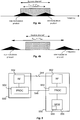
- a spurious response is generated for each frequency step of the external interference for which the intermodulation product falls in the receive channel, as illustrated in figure 4a .
- the intermodulation product is moved either by one or two steps, F Step , for the lowest order nonlinearities of the receiver per frequency step of the external interferer.
- the step size could be chosen proportional to the bandwidth of the receive channel. It is desirable to choose the step size:
- the step size is chosen in proportion to the receive channel bandwidth under test so that the test time is reduced while still meeting the purpose of the test.
- FIG. 5 illustrates a radio device 500 in the form of a transceiver that is configured for OOBB testing by test equipment 550.
- the radio device 500 is capable of duplex transmission.
- the device 500 comprises a radio frequency, RF, receiver 502 that may support one or several channel bandwidths.
- the test equipment 550 is capable of generating an external interferer, i.e. an interfering radio signal, that is controlled by a controller 554 in cooperation with RF circuitry 552.
- Software 558 resides in a memory 556 and controls the testing as will be described below.
- the software 558 can be provided to the equipment 550 by means of a non-transitory computer program product that is realized on any suitable software carrier such as a disc or flash memory etc.
- a radio frequency connection 544 is used to convey the generated interferer from the test equipment 550 to the receiver.
- the connection can be an air interface as well as a galvanic, capacitive or inductive connection.
- a processing unit 504 in the device 500 is configured to report, via a connection 545, responses from the radio frequency receiver 502 to the test equipment 550.
- the interferer is swept in frequency using a preselected step size.
- the interferer is not swept across the receive channel (e.g. out-of-band or in-band blocking test, the latter still excludes the actual receive channel).
- the step size is chosen proportional to the bandwidth of the receive channel B ch with a step size less than or equal to B ch /2 so that a frequency step makes sure any spurious response due to internal signals in the radio device 500 is captured (the spurious response can move by two steps so F Step ⁇ B ch /2).
- the external interferer is swept using the said frequency step and the selectivity and spurious responses are recorded.
- the step size may be chosen slightly larger, B ch /2 ⁇ F Step ⁇ B ch , but at a possible penalty of test accuracy.
- Figures 6a and 6b are flow charts of examples of such a method.
- Figure 6a illustrates a more general realization of a test method and figure 6b is a more specific example.
- the method in figure 6a commences with a determination step 601 where a respective frequency bandwidth (B Ch ) of a plurality of receive channels of the radio equipment is determined.
- a proportionality constant is selected, in a selection step 603, for a frequency step size.
- interfering radio signals are generated in a generation step 605.
- the generation step involves controlling the interfering radio signals to stepwise sweep in frequency outside of each respective receive channel, where the stepwise sweeping of the interfering frequency is performed with a frequency step size that is a product of the respective bandwidth and the selected proportionality constant.
- FIG. 6b A more detailed example of such a test method is illustrated in figure 6b .
- the method of figure 6b commences with a setting step 602 where the frequency step F Step (selected as above), a starting frequency F 0 and an end frequency F 1 for the sweeping are set.
- the frequency of the interferer i.e. the interfering signal, F is then set to the starting frequency F 0 in a setting step 604.
- the interfering signal at frequency F is then generated and provided to the receiver 500 in a generating step 606.
- the interfering signal is received in the RF receiver 502 of the device 500 and spurious responses are provided by the processing unit 504 via the connection 545 and recorded, in a recording step 608, in the test equipment 550.
- the sweeping then continues by incrementing, in a setting step 610, the frequency F of the interferer by F Step .
- Results show that the test time for selectivity test can be significantly reduced using these embodiments.
- the step size that is currently used in testing procedures is 1 MHz and the out-of-band blocking tests requires around 8 hours for completion.
- the bandwidths supported are up to 20 MHz.
- a choice of step size as: F Step max 1 , min ⁇ 0.5 BW Channel ⁇ 5 in MHz between 1 and 5 MHz can reduce the test time by a factor of 5.
- the function ⁇ x ⁇ is the floor function, which returns the largest integer not greater than x.
- the following table illustrates the frequency step sizes obtained by using equation 1.
- the bandwidth can be up to 20 MHz.
- the upper limit of 5 MHz is chosen here to be able to record the frequency selectivity with sufficient frequency granularity.
- the number of allowed spurious responses for E-UTRA is also reduced, inversely proportional to the step size employed.
Landscapes
- Engineering & Computer Science (AREA)
- Computer Networks & Wireless Communication (AREA)
- Signal Processing (AREA)
- Physics & Mathematics (AREA)
- Electromagnetism (AREA)
- Quality & Reliability (AREA)
- Monitoring And Testing Of Transmission In General (AREA)
- Noise Elimination (AREA)
Claims (7)
- Verfahren zum Testen einer Funkausrüstung (500), umfassend ein Erzeugen eines Störsignals, umfassend die Schritte zum:- Ermitteln (601) einer jeweiligen Frequenzbandbreite, BCh, von mehreren Empfangskanälen der Funkausrüstung,- Erzeugen (605) von Störfunksignalen für jeden jeweiligen Empfangskanal und Steuern der Störfunksignale, um einen schrittweisen Frequenz-Sweep außerhalb jedes jeweiligen Empfangskanals auszuführen, wo der schrittweise Sweep der Störfrequenz mit einer jeweiligen Frequenzschrittgröße durchgeführt wird, und- Erfassen (607) jeglichen Nebenempfangs im jeweiligen Empfangskanal,dadurch gekennzeichnet, dass das Verfahren des Weiteren umfasst:- Auswählen (603) einer Proportionalitätskonstante für die Frequenzschrittgröße für jeden jeweiligen Empfangskanal und- Durchführen des schrittweisen Sweeps der Störfrequenz mit der jeweiligen Frequenzschrittgröße, die ein Produkt der jeweiligen Bandbreite und der gewählten Proportionalitätskonstante ist.
- Verfahren nach Anspruch 1, wobei die Auswahl der Proportionalitätskonstante für eine Frequenzschrittgröße Auswählen eines Wertes umfasst, der kleiner oder gleich 1/2 ist.
- Verfahren nach Anspruch 1, wobei die Auswahl der Proportionalitätskonstante für eine Frequenzschrittgröße ein Auswählen eines Wertes umfasst, der ein Intervall ist, das durch den Ausdruck definiert ist: max{S0,min(└0,5BCh┘, S1)}, wo So 1 MHz ist und S1 5 MHz ist und die Funktion └...┘ die Abrundungsfunktion ist und BCh von 1,4 bis 20 MHz reicht.
- Vorrichtung (550) zum Testen einer Funkausrüstung (500), die Vorrichtung (550) umfassend eine Funkfrequenz-, RF, Schaltung (552), eine Steuerschaltung (554) und eine Speicherschaltung (556), die konfiguriert sind, ein Störsignal zu erzeugen, wobei die RF-Schaltung, Steuerschaltung und Speicherschaltung konfiguriert sind zum:- Ermitteln einer jeweiligen Frequenzbandbreite, BCh, von mehreren Empfangskanälen der Funkausrüstung,- Erzeugen von Störfunksignalen für jeden jeweiligen Empfangskanal und Steuern der Störfunksignale für einen schrittweisen Frequenz-Sweep außerhalb jedes jeweiligen Empfangskanals, wo der schrittweise Sweep der Störfrequenz mit einer jeweiligen Frequenzschrittgröße durchgeführt wird, und- Erfassen jeglichen Nebenempfangs im jeweiligen Empfangskanal,dadurch gekennzeichnet, dass die RF-Schaltung, Steuerschaltung und Speicherschaltung des Weiteren konfiguriert sind zum:- Auswählen (603) einer Proportionalitätskonstante für die Frequenzschrittgröße für jeden jeweiligen Empfangskanal und zum- Durchführen des schrittweisen Sweeps der Störfrequenz mit der jeweiligen Frequenzschrittgröße, die ein Produkt der jeweiligen Bandbreite und der jeweiligen Proportionalitätskonstante ist.
- Vorrichtung nach Anspruch 4, wobei die Konfiguration der RF-Schaltung, Steuerschaltung und Speicherschaltung, um die Proportionalitätskonstante für eine Frequenzschrittgröße auszuwählen, eine Konfiguration umfasst, um einen Wert auszuwählen der kleiner oder gleich 1/2 ist.
- Vorrichtung nach Anspruch 4, wobei die Konfiguration der RF-Schaltung, Steuerschaltung und Speicherschaltung, um die Proportionalitätskonstante für eine Frequenzschrittgröße auszuwählen, eine Konfiguration umfasst, um einen Wert auszuwählen der in einem Intervall ist, das durch den Ausdruck definiert ist: max{S0,min(└0,5BCh┘, S1)}, wo S0 1 MHz ist und S1 5 MHz ist und die Funktion └...┘ die Abrundungsfunktion ist und BCh von 1,4 bis 20 MHz reicht.
- Nicht-flüchtiges Computerprogrammprodukt, umfassend Software-Anweisungen (558), die, wenn in einem Prozessor ausgeführt, das Verfahren nach einem der Ansprüche 1 bis 3 durchführen.
Applications Claiming Priority (2)
| Application Number | Priority Date | Filing Date | Title |
|---|---|---|---|
| US201261679848P | 2012-08-06 | 2012-08-06 | |
| PCT/EP2013/066350 WO2014023678A1 (en) | 2012-08-06 | 2013-08-05 | Improved selectivity test |
Publications (2)
| Publication Number | Publication Date |
|---|---|
| EP2880786A1 EP2880786A1 (de) | 2015-06-10 |
| EP2880786B1 true EP2880786B1 (de) | 2017-06-14 |
Family
ID=49000452
Family Applications (1)
| Application Number | Title | Priority Date | Filing Date |
|---|---|---|---|
| EP13750524.4A Not-in-force EP2880786B1 (de) | 2012-08-06 | 2013-08-05 | Verbesserter selektivitätstest |
Country Status (6)
| Country | Link |
|---|---|
| US (1) | US9553682B2 (de) |
| EP (1) | EP2880786B1 (de) |
| JP (1) | JP6219950B2 (de) |
| AU (1) | AU2013301581B2 (de) |
| MX (1) | MX341891B (de) |
| WO (1) | WO2014023678A1 (de) |
Families Citing this family (4)
| Publication number | Priority date | Publication date | Assignee | Title |
|---|---|---|---|---|
| JP2688535B2 (ja) | 1990-10-12 | 1997-12-10 | 川崎製鉄株式会社 | 溶接ワイヤ送給制御方法及び装置 |
| CN104579521B (zh) * | 2014-12-25 | 2017-04-26 | 中国科学院信息工程研究所 | 基于谱质心的视频泄漏信号自动检测方法及系统 |
| JP6383380B2 (ja) * | 2016-04-27 | 2018-08-29 | アンリツ株式会社 | 移動体端末試験装置および試験方法 |
| CN116244132A (zh) * | 2023-03-16 | 2023-06-09 | 深圳市千分一智能技术有限公司 | 主动笔的接收性能测试方法、设备和存储介质 |
Family Cites Families (7)
| Publication number | Priority date | Publication date | Assignee | Title |
|---|---|---|---|---|
| JP3536072B2 (ja) * | 1994-11-17 | 2004-06-07 | アジレント・テクノロジーズ・インク | 受信機の感度及び妨害波特性測定方法ならびに測定装置 |
| US6418162B1 (en) * | 1998-09-25 | 2002-07-09 | Tektronix, Inc. | Frequency spectrum measurement apparatus |
| JP2001358662A (ja) * | 2000-06-15 | 2001-12-26 | Oki Electric Ind Co Ltd | 受信機能自己診断方法及び装置 |
| US7310504B2 (en) * | 2004-03-26 | 2007-12-18 | Agilent Technologies, Inc. | IF frequency response characterization employing overlapping frequency bands |
| JP4442390B2 (ja) * | 2004-10-27 | 2010-03-31 | 日本電気株式会社 | 無線基地局試験装置及び無線基地局試験方法 |
| JP2009236818A (ja) * | 2008-03-28 | 2009-10-15 | Yamaha Corp | 周波数特性測定装置 |
| US8995517B2 (en) * | 2010-07-21 | 2015-03-31 | Kaelus Pty Ltd | Method and apparatus for locating faults in communications networks |
-
2013
- 2013-08-05 WO PCT/EP2013/066350 patent/WO2014023678A1/en not_active Ceased
- 2013-08-05 MX MX2015001642A patent/MX341891B/es active IP Right Grant
- 2013-08-05 AU AU2013301581A patent/AU2013301581B2/en not_active Ceased
- 2013-08-05 US US14/419,343 patent/US9553682B2/en not_active Expired - Fee Related
- 2013-08-05 EP EP13750524.4A patent/EP2880786B1/de not_active Not-in-force
- 2013-08-05 JP JP2015525847A patent/JP6219950B2/ja not_active Expired - Fee Related
Non-Patent Citations (1)
| Title |
|---|
| None * |
Also Published As
| Publication number | Publication date |
|---|---|
| JP6219950B2 (ja) | 2017-10-25 |
| US20160013874A1 (en) | 2016-01-14 |
| EP2880786A1 (de) | 2015-06-10 |
| US9553682B2 (en) | 2017-01-24 |
| WO2014023678A1 (en) | 2014-02-13 |
| MX2015001642A (es) | 2015-04-08 |
| JP2015530793A (ja) | 2015-10-15 |
| AU2013301581B2 (en) | 2016-05-26 |
| AU2013301581A1 (en) | 2015-02-26 |
| MX341891B (es) | 2016-09-07 |
Similar Documents
| Publication | Publication Date | Title |
|---|---|---|
| US20090058426A1 (en) | Electromagnetic shielding defect monitoring system and method for using the same | |
| CN104601258B (zh) | 一种车载通信系统同车多机互扰测试方法 | |
| US11175327B2 (en) | Radiated emission measurement method and radiated emission measurement system | |
| US10567093B1 (en) | Combined parallel processing of spectral information for a radio frequency environment | |
| US9553682B2 (en) | Selectivity test | |
| DE102014001399A1 (de) | RFI-Abschwächung über die Arbeitszyklussteuerung | |
| CN105450318A (zh) | Agc校准方法及装置 | |
| CN102547781A (zh) | 互调干扰小区的确定方法和装置 | |
| CN107454239A (zh) | 移动终端测试装置及测试方法 | |
| CN113702720A (zh) | 一种多检波方式辐射杂散测试方法及检测系统 | |
| CN106341195A (zh) | 一种面向射频前端的校准系统及校准方法 | |
| CN116346250B (zh) | 补偿系数确定方法、装置及设备 | |
| US9991977B2 (en) | Smart testing management | |
| CN104581756B (zh) | 一种确定干扰源的方法及装置 | |
| CN117092384A (zh) | 屏蔽装置、信息确定方法、电子设备和测试设备 | |
| CN117394932A (zh) | 一种杂散自动测试方法及系统 | |
| CN109142864B (zh) | 基于频谱的快速无线电检测方法 | |
| CN117907762A (zh) | 一种特高频局部放电检测方法及装置 | |
| Kuester et al. | Radio spectrum occupancy measurements amid COVID-19 telework and telehealth | |
| CN106412977B (zh) | 互调测试的方法及装置 | |
| CN104902495B (zh) | 一种评估td‑lte系统干扰的方法和td‑lte系统 | |
| EP2672639A1 (de) | Interferenzreduktionsverfahren für Funkübertragungssystem mit Vielfachmodus | |
| CN112003652A (zh) | 终端设备的射频调试方法、装置及计算机可读存储介质 | |
| US12467961B2 (en) | Method of determining a setting for performing a spurious emission measurement and method of performing a spurious emission measurement | |
| CN106817141B (zh) | 一种信号检测方法、装置及设备 |
Legal Events
| Date | Code | Title | Description |
|---|---|---|---|
| PUAI | Public reference made under article 153(3) epc to a published international application that has entered the european phase |
Free format text: ORIGINAL CODE: 0009012 |
|
| 17P | Request for examination filed |
Effective date: 20150213 |
|
| AK | Designated contracting states |
Kind code of ref document: A1 Designated state(s): AL AT BE BG CH CY CZ DE DK EE ES FI FR GB GR HR HU IE IS IT LI LT LU LV MC MK MT NL NO PL PT RO RS SE SI SK SM TR |
|
| AX | Request for extension of the european patent |
Extension state: BA ME |
|
| DAX | Request for extension of the european patent (deleted) | ||
| REG | Reference to a national code |
Ref country code: DE Ref legal event code: R079 Ref document number: 602013022276 Country of ref document: DE Free format text: PREVIOUS MAIN CLASS: H04B0017000000 Ipc: H04W0024060000 |
|
| GRAP | Despatch of communication of intention to grant a patent |
Free format text: ORIGINAL CODE: EPIDOSNIGR1 |
|
| RIC1 | Information provided on ipc code assigned before grant |
Ipc: H04B 17/29 20150101ALI20170206BHEP Ipc: H04B 17/354 20150101ALI20170206BHEP Ipc: H04B 17/00 20150101ALI20170206BHEP Ipc: H04W 24/06 20090101AFI20170206BHEP |
|
| INTG | Intention to grant announced |
Effective date: 20170224 |
|
| GRAS | Grant fee paid |
Free format text: ORIGINAL CODE: EPIDOSNIGR3 |
|
| GRAA | (expected) grant |
Free format text: ORIGINAL CODE: 0009210 |
|
| AK | Designated contracting states |
Kind code of ref document: B1 Designated state(s): AL AT BE BG CH CY CZ DE DK EE ES FI FR GB GR HR HU IE IS IT LI LT LU LV MC MK MT NL NO PL PT RO RS SE SI SK SM TR |
|
| REG | Reference to a national code |
Ref country code: GB Ref legal event code: FG4D |
|
| REG | Reference to a national code |
Ref country code: CH Ref legal event code: EP Ref country code: AT Ref legal event code: REF Ref document number: 902005 Country of ref document: AT Kind code of ref document: T Effective date: 20170615 |
|
| REG | Reference to a national code |
Ref country code: IE Ref legal event code: FG4D |
|
| REG | Reference to a national code |
Ref country code: DE Ref legal event code: R096 Ref document number: 602013022276 Country of ref document: DE |
|
| REG | Reference to a national code |
Ref country code: FR Ref legal event code: PLFP Year of fee payment: 5 |
|
| REG | Reference to a national code |
Ref country code: NL Ref legal event code: MP Effective date: 20170614 |
|
| REG | Reference to a national code |
Ref country code: LT Ref legal event code: MG4D |
|
| PG25 | Lapsed in a contracting state [announced via postgrant information from national office to epo] |
Ref country code: HR Free format text: LAPSE BECAUSE OF FAILURE TO SUBMIT A TRANSLATION OF THE DESCRIPTION OR TO PAY THE FEE WITHIN THE PRESCRIBED TIME-LIMIT Effective date: 20170614 Ref country code: NO Free format text: LAPSE BECAUSE OF FAILURE TO SUBMIT A TRANSLATION OF THE DESCRIPTION OR TO PAY THE FEE WITHIN THE PRESCRIBED TIME-LIMIT Effective date: 20170914 Ref country code: FI Free format text: LAPSE BECAUSE OF FAILURE TO SUBMIT A TRANSLATION OF THE DESCRIPTION OR TO PAY THE FEE WITHIN THE PRESCRIBED TIME-LIMIT Effective date: 20170614 Ref country code: LT Free format text: LAPSE BECAUSE OF FAILURE TO SUBMIT A TRANSLATION OF THE DESCRIPTION OR TO PAY THE FEE WITHIN THE PRESCRIBED TIME-LIMIT Effective date: 20170614 Ref country code: GR Free format text: LAPSE BECAUSE OF FAILURE TO SUBMIT A TRANSLATION OF THE DESCRIPTION OR TO PAY THE FEE WITHIN THE PRESCRIBED TIME-LIMIT Effective date: 20170915 |
|
| REG | Reference to a national code |
Ref country code: AT Ref legal event code: MK05 Ref document number: 902005 Country of ref document: AT Kind code of ref document: T Effective date: 20170614 |
|
| PG25 | Lapsed in a contracting state [announced via postgrant information from national office to epo] |
Ref country code: RS Free format text: LAPSE BECAUSE OF FAILURE TO SUBMIT A TRANSLATION OF THE DESCRIPTION OR TO PAY THE FEE WITHIN THE PRESCRIBED TIME-LIMIT Effective date: 20170614 Ref country code: SE Free format text: LAPSE BECAUSE OF FAILURE TO SUBMIT A TRANSLATION OF THE DESCRIPTION OR TO PAY THE FEE WITHIN THE PRESCRIBED TIME-LIMIT Effective date: 20170614 Ref country code: LV Free format text: LAPSE BECAUSE OF FAILURE TO SUBMIT A TRANSLATION OF THE DESCRIPTION OR TO PAY THE FEE WITHIN THE PRESCRIBED TIME-LIMIT Effective date: 20170614 Ref country code: BG Free format text: LAPSE BECAUSE OF FAILURE TO SUBMIT A TRANSLATION OF THE DESCRIPTION OR TO PAY THE FEE WITHIN THE PRESCRIBED TIME-LIMIT Effective date: 20170914 Ref country code: NL Free format text: LAPSE BECAUSE OF FAILURE TO SUBMIT A TRANSLATION OF THE DESCRIPTION OR TO PAY THE FEE WITHIN THE PRESCRIBED TIME-LIMIT Effective date: 20170614 |
|
| PG25 | Lapsed in a contracting state [announced via postgrant information from national office to epo] |
Ref country code: SK Free format text: LAPSE BECAUSE OF FAILURE TO SUBMIT A TRANSLATION OF THE DESCRIPTION OR TO PAY THE FEE WITHIN THE PRESCRIBED TIME-LIMIT Effective date: 20170614 Ref country code: CZ Free format text: LAPSE BECAUSE OF FAILURE TO SUBMIT A TRANSLATION OF THE DESCRIPTION OR TO PAY THE FEE WITHIN THE PRESCRIBED TIME-LIMIT Effective date: 20170614 Ref country code: RO Free format text: LAPSE BECAUSE OF FAILURE TO SUBMIT A TRANSLATION OF THE DESCRIPTION OR TO PAY THE FEE WITHIN THE PRESCRIBED TIME-LIMIT Effective date: 20170614 Ref country code: AT Free format text: LAPSE BECAUSE OF FAILURE TO SUBMIT A TRANSLATION OF THE DESCRIPTION OR TO PAY THE FEE WITHIN THE PRESCRIBED TIME-LIMIT Effective date: 20170614 Ref country code: EE Free format text: LAPSE BECAUSE OF FAILURE TO SUBMIT A TRANSLATION OF THE DESCRIPTION OR TO PAY THE FEE WITHIN THE PRESCRIBED TIME-LIMIT Effective date: 20170614 |
|
| PG25 | Lapsed in a contracting state [announced via postgrant information from national office to epo] |
Ref country code: SM Free format text: LAPSE BECAUSE OF FAILURE TO SUBMIT A TRANSLATION OF THE DESCRIPTION OR TO PAY THE FEE WITHIN THE PRESCRIBED TIME-LIMIT Effective date: 20170614 Ref country code: IS Free format text: LAPSE BECAUSE OF FAILURE TO SUBMIT A TRANSLATION OF THE DESCRIPTION OR TO PAY THE FEE WITHIN THE PRESCRIBED TIME-LIMIT Effective date: 20171014 Ref country code: IT Free format text: LAPSE BECAUSE OF FAILURE TO SUBMIT A TRANSLATION OF THE DESCRIPTION OR TO PAY THE FEE WITHIN THE PRESCRIBED TIME-LIMIT Effective date: 20170614 Ref country code: ES Free format text: LAPSE BECAUSE OF FAILURE TO SUBMIT A TRANSLATION OF THE DESCRIPTION OR TO PAY THE FEE WITHIN THE PRESCRIBED TIME-LIMIT Effective date: 20170614 Ref country code: PL Free format text: LAPSE BECAUSE OF FAILURE TO SUBMIT A TRANSLATION OF THE DESCRIPTION OR TO PAY THE FEE WITHIN THE PRESCRIBED TIME-LIMIT Effective date: 20170614 |
|
| REG | Reference to a national code |
Ref country code: DE Ref legal event code: R097 Ref document number: 602013022276 Country of ref document: DE |
|
| REG | Reference to a national code |
Ref country code: CH Ref legal event code: PL |
|
| PG25 | Lapsed in a contracting state [announced via postgrant information from national office to epo] |
Ref country code: MC Free format text: LAPSE BECAUSE OF FAILURE TO SUBMIT A TRANSLATION OF THE DESCRIPTION OR TO PAY THE FEE WITHIN THE PRESCRIBED TIME-LIMIT Effective date: 20170614 |
|
| PLBE | No opposition filed within time limit |
Free format text: ORIGINAL CODE: 0009261 |
|
| STAA | Information on the status of an ep patent application or granted ep patent |
Free format text: STATUS: NO OPPOSITION FILED WITHIN TIME LIMIT |
|
| PG25 | Lapsed in a contracting state [announced via postgrant information from national office to epo] |
Ref country code: CH Free format text: LAPSE BECAUSE OF NON-PAYMENT OF DUE FEES Effective date: 20170831 Ref country code: DK Free format text: LAPSE BECAUSE OF FAILURE TO SUBMIT A TRANSLATION OF THE DESCRIPTION OR TO PAY THE FEE WITHIN THE PRESCRIBED TIME-LIMIT Effective date: 20170614 Ref country code: LI Free format text: LAPSE BECAUSE OF NON-PAYMENT OF DUE FEES Effective date: 20170831 |
|
| 26N | No opposition filed |
Effective date: 20180315 |
|
| REG | Reference to a national code |
Ref country code: IE Ref legal event code: MM4A |
|
| REG | Reference to a national code |
Ref country code: BE Ref legal event code: MM Effective date: 20170831 |
|
| PG25 | Lapsed in a contracting state [announced via postgrant information from national office to epo] |
Ref country code: LU Free format text: LAPSE BECAUSE OF NON-PAYMENT OF DUE FEES Effective date: 20170805 |
|
| PG25 | Lapsed in a contracting state [announced via postgrant information from national office to epo] |
Ref country code: IE Free format text: LAPSE BECAUSE OF NON-PAYMENT OF DUE FEES Effective date: 20170805 |
|
| REG | Reference to a national code |
Ref country code: FR Ref legal event code: PLFP Year of fee payment: 6 |
|
| PG25 | Lapsed in a contracting state [announced via postgrant information from national office to epo] |
Ref country code: SI Free format text: LAPSE BECAUSE OF FAILURE TO SUBMIT A TRANSLATION OF THE DESCRIPTION OR TO PAY THE FEE WITHIN THE PRESCRIBED TIME-LIMIT Effective date: 20170614 Ref country code: BE Free format text: LAPSE BECAUSE OF NON-PAYMENT OF DUE FEES Effective date: 20170831 |
|
| PG25 | Lapsed in a contracting state [announced via postgrant information from national office to epo] |
Ref country code: MT Free format text: LAPSE BECAUSE OF NON-PAYMENT OF DUE FEES Effective date: 20170805 |
|
| PG25 | Lapsed in a contracting state [announced via postgrant information from national office to epo] |
Ref country code: HU Free format text: LAPSE BECAUSE OF FAILURE TO SUBMIT A TRANSLATION OF THE DESCRIPTION OR TO PAY THE FEE WITHIN THE PRESCRIBED TIME-LIMIT; INVALID AB INITIO Effective date: 20130805 |
|
| PG25 | Lapsed in a contracting state [announced via postgrant information from national office to epo] |
Ref country code: CY Free format text: LAPSE BECAUSE OF FAILURE TO SUBMIT A TRANSLATION OF THE DESCRIPTION OR TO PAY THE FEE WITHIN THE PRESCRIBED TIME-LIMIT Effective date: 20170614 |
|
| PG25 | Lapsed in a contracting state [announced via postgrant information from national office to epo] |
Ref country code: MK Free format text: LAPSE BECAUSE OF FAILURE TO SUBMIT A TRANSLATION OF THE DESCRIPTION OR TO PAY THE FEE WITHIN THE PRESCRIBED TIME-LIMIT Effective date: 20170614 |
|
| PG25 | Lapsed in a contracting state [announced via postgrant information from national office to epo] |
Ref country code: TR Free format text: LAPSE BECAUSE OF FAILURE TO SUBMIT A TRANSLATION OF THE DESCRIPTION OR TO PAY THE FEE WITHIN THE PRESCRIBED TIME-LIMIT Effective date: 20170614 |
|
| PG25 | Lapsed in a contracting state [announced via postgrant information from national office to epo] |
Ref country code: PT Free format text: LAPSE BECAUSE OF FAILURE TO SUBMIT A TRANSLATION OF THE DESCRIPTION OR TO PAY THE FEE WITHIN THE PRESCRIBED TIME-LIMIT Effective date: 20170614 |
|
| PG25 | Lapsed in a contracting state [announced via postgrant information from national office to epo] |
Ref country code: AL Free format text: LAPSE BECAUSE OF FAILURE TO SUBMIT A TRANSLATION OF THE DESCRIPTION OR TO PAY THE FEE WITHIN THE PRESCRIBED TIME-LIMIT Effective date: 20170614 |
|
| PGFP | Annual fee paid to national office [announced via postgrant information from national office to epo] |
Ref country code: FR Payment date: 20210825 Year of fee payment: 9 |
|
| PGFP | Annual fee paid to national office [announced via postgrant information from national office to epo] |
Ref country code: GB Payment date: 20210827 Year of fee payment: 9 |
|
| PGFP | Annual fee paid to national office [announced via postgrant information from national office to epo] |
Ref country code: DE Payment date: 20220629 Year of fee payment: 10 |
|
| GBPC | Gb: european patent ceased through non-payment of renewal fee |
Effective date: 20220805 |
|
| PG25 | Lapsed in a contracting state [announced via postgrant information from national office to epo] |
Ref country code: FR Free format text: LAPSE BECAUSE OF NON-PAYMENT OF DUE FEES Effective date: 20220831 |
|
| PG25 | Lapsed in a contracting state [announced via postgrant information from national office to epo] |
Ref country code: GB Free format text: LAPSE BECAUSE OF NON-PAYMENT OF DUE FEES Effective date: 20220805 |
|
| REG | Reference to a national code |
Ref country code: DE Ref legal event code: R119 Ref document number: 602013022276 Country of ref document: DE |
|
| PG25 | Lapsed in a contracting state [announced via postgrant information from national office to epo] |
Ref country code: DE Free format text: LAPSE BECAUSE OF NON-PAYMENT OF DUE FEES Effective date: 20240301 |