EP2880414B1 - Apparatus for monitoring of valves and methods of operating the same - Google Patents
Apparatus for monitoring of valves and methods of operating the same Download PDFInfo
- Publication number
- EP2880414B1 EP2880414B1 EP13750429.6A EP13750429A EP2880414B1 EP 2880414 B1 EP2880414 B1 EP 2880414B1 EP 13750429 A EP13750429 A EP 13750429A EP 2880414 B1 EP2880414 B1 EP 2880414B1
- Authority
- EP
- European Patent Office
- Prior art keywords
- passage
- valve stem
- valve
- fluid
- sensing device
- Prior art date
- Legal status (The legal status is an assumption and is not a legal conclusion. Google has not performed a legal analysis and makes no representation as to the accuracy of the status listed.)
- Active
Links
Images


Classifications
-
- F—MECHANICAL ENGINEERING; LIGHTING; HEATING; WEAPONS; BLASTING
- F01—MACHINES OR ENGINES IN GENERAL; ENGINE PLANTS IN GENERAL; STEAM ENGINES
- F01D—NON-POSITIVE DISPLACEMENT MACHINES OR ENGINES, e.g. STEAM TURBINES
- F01D17/00—Regulating or controlling by varying flow
- F01D17/02—Arrangement of sensing elements
-
- F—MECHANICAL ENGINEERING; LIGHTING; HEATING; WEAPONS; BLASTING
- F01—MACHINES OR ENGINES IN GENERAL; ENGINE PLANTS IN GENERAL; STEAM ENGINES
- F01D—NON-POSITIVE DISPLACEMENT MACHINES OR ENGINES, e.g. STEAM TURBINES
- F01D21/00—Shutting-down of machines or engines, e.g. in emergency; Regulating, controlling, or safety means not otherwise provided for
- F01D21/003—Arrangements for testing or measuring
-
- F—MECHANICAL ENGINEERING; LIGHTING; HEATING; WEAPONS; BLASTING
- F01—MACHINES OR ENGINES IN GENERAL; ENGINE PLANTS IN GENERAL; STEAM ENGINES
- F01D—NON-POSITIVE DISPLACEMENT MACHINES OR ENGINES, e.g. STEAM TURBINES
- F01D21/00—Shutting-down of machines or engines, e.g. in emergency; Regulating, controlling, or safety means not otherwise provided for
- F01D21/14—Shutting-down of machines or engines, e.g. in emergency; Regulating, controlling, or safety means not otherwise provided for responsive to other specific conditions
-
- F—MECHANICAL ENGINEERING; LIGHTING; HEATING; WEAPONS; BLASTING
- F16—ENGINEERING ELEMENTS AND UNITS; GENERAL MEASURES FOR PRODUCING AND MAINTAINING EFFECTIVE FUNCTIONING OF MACHINES OR INSTALLATIONS; THERMAL INSULATION IN GENERAL
- F16K—VALVES; TAPS; COCKS; ACTUATING-FLOATS; DEVICES FOR VENTING OR AERATING
- F16K1/00—Lift valves or globe valves, i.e. cut-off apparatus with closure members having at least a component of their opening and closing motion perpendicular to the closing faces
- F16K1/12—Lift valves or globe valves, i.e. cut-off apparatus with closure members having at least a component of their opening and closing motion perpendicular to the closing faces with streamlined valve member around which the fluid flows when the valve is opened
-
- F—MECHANICAL ENGINEERING; LIGHTING; HEATING; WEAPONS; BLASTING
- F16—ENGINEERING ELEMENTS AND UNITS; GENERAL MEASURES FOR PRODUCING AND MAINTAINING EFFECTIVE FUNCTIONING OF MACHINES OR INSTALLATIONS; THERMAL INSULATION IN GENERAL
- F16K—VALVES; TAPS; COCKS; ACTUATING-FLOATS; DEVICES FOR VENTING OR AERATING
- F16K37/00—Special means in or on valves or other cut-off apparatus for indicating or recording operation thereof, or for enabling an alarm to be given
- F16K37/0025—Electrical or magnetic means
- F16K37/005—Electrical or magnetic means for measuring fluid parameters
-
- F—MECHANICAL ENGINEERING; LIGHTING; HEATING; WEAPONS; BLASTING
- F16—ENGINEERING ELEMENTS AND UNITS; GENERAL MEASURES FOR PRODUCING AND MAINTAINING EFFECTIVE FUNCTIONING OF MACHINES OR INSTALLATIONS; THERMAL INSULATION IN GENERAL
- F16K—VALVES; TAPS; COCKS; ACTUATING-FLOATS; DEVICES FOR VENTING OR AERATING
- F16K41/00—Spindle sealings
-
- G—PHYSICS
- G01—MEASURING; TESTING
- G01M—TESTING STATIC OR DYNAMIC BALANCE OF MACHINES OR STRUCTURES; TESTING OF STRUCTURES OR APPARATUS, NOT OTHERWISE PROVIDED FOR
- G01M3/00—Investigating fluid-tightness of structures
- G01M3/02—Investigating fluid-tightness of structures by using fluid or vacuum
- G01M3/26—Investigating fluid-tightness of structures by using fluid or vacuum by measuring rate of loss or gain of fluid, e.g. by pressure-responsive devices, by flow detectors
- G01M3/28—Investigating fluid-tightness of structures by using fluid or vacuum by measuring rate of loss or gain of fluid, e.g. by pressure-responsive devices, by flow detectors for pipes, cables or tubes; for pipe joints or seals; for valves ; for welds
- G01M3/2876—Investigating fluid-tightness of structures by using fluid or vacuum by measuring rate of loss or gain of fluid, e.g. by pressure-responsive devices, by flow detectors for pipes, cables or tubes; for pipe joints or seals; for valves ; for welds for valves
-
- F—MECHANICAL ENGINEERING; LIGHTING; HEATING; WEAPONS; BLASTING
- F16—ENGINEERING ELEMENTS AND UNITS; GENERAL MEASURES FOR PRODUCING AND MAINTAINING EFFECTIVE FUNCTIONING OF MACHINES OR INSTALLATIONS; THERMAL INSULATION IN GENERAL
- F16K—VALVES; TAPS; COCKS; ACTUATING-FLOATS; DEVICES FOR VENTING OR AERATING
- F16K37/00—Special means in or on valves or other cut-off apparatus for indicating or recording operation thereof, or for enabling an alarm to be given
-
- Y—GENERAL TAGGING OF NEW TECHNOLOGICAL DEVELOPMENTS; GENERAL TAGGING OF CROSS-SECTIONAL TECHNOLOGIES SPANNING OVER SEVERAL SECTIONS OF THE IPC; TECHNICAL SUBJECTS COVERED BY FORMER USPC CROSS-REFERENCE ART COLLECTIONS [XRACs] AND DIGESTS
- Y10—TECHNICAL SUBJECTS COVERED BY FORMER USPC
- Y10T—TECHNICAL SUBJECTS COVERED BY FORMER US CLASSIFICATION
- Y10T137/00—Fluid handling
- Y10T137/0318—Processes
-
- Y—GENERAL TAGGING OF NEW TECHNOLOGICAL DEVELOPMENTS; GENERAL TAGGING OF CROSS-SECTIONAL TECHNOLOGIES SPANNING OVER SEVERAL SECTIONS OF THE IPC; TECHNICAL SUBJECTS COVERED BY FORMER USPC CROSS-REFERENCE ART COLLECTIONS [XRACs] AND DIGESTS
- Y10—TECHNICAL SUBJECTS COVERED BY FORMER USPC
- Y10T—TECHNICAL SUBJECTS COVERED BY FORMER US CLASSIFICATION
- Y10T137/00—Fluid handling
- Y10T137/8158—With indicator, register, recorder, alarm or inspection means
- Y10T137/8326—Fluid pressure responsive indicator, recorder or alarm
Definitions
- the embodiments described herein relate generally to fluid systems and, more particularly, to methods and apparatus that facilitate erosion detection of valves in steam systems.
- At least some steam turbines are coupled to steam generators that include at least one fossil fuel-fired boiler and/or at least one heat recovery steam generator (HRSG).
- Boilers and HRSGs include tubing that converts water to steam.
- the steam turbine is coupled to the boiler/HRSG via steam piping.
- Some known steam turbines include steam turbine inlet isolation valves and steam turbine control valves. Such isolation and control valves may be combined into a single valve assembly. Steam is channeled to the steam turbine via a steam transport system that includes the steam piping, isolation valves, and control valves.
- EP1217352A1 discloses a valve stem assembly comprising at least one wall (external surface) and at least one passage said valve stem assembly, said at least one passage defines a first opening, wherein at least one portion of said at least one wall defines an erosion site that is configured to undergo contact with solid particles such that a second opening of said passage is defined; and at least one sensing device coupled in flow communication with said at least one passage through said first opening, said at least one sensing device is configured to transmit a signal representative of an increased fluid flow through said at least one passage.
- US 4874007 discloses a wear indicator in a flow restrictor valve, which gives visual indication when erosive fluid jets has worn through the wall of a turbulence diffuser.
- a valve in one aspect, includes a valve stem assembly including at least one wall and at least one passage at least partially defined within the valve stem assembly.
- the at least one passage defines a first opening.
- At least one portion of the at least one wall defines an erosion site that is configured to undergo contact with solid particles such that a second opening of the passage is defined.
- the valve also includes at least one sensing device coupled in flow communication with the at least one passage through the first opening. The at least one sensing device is configured to transmit a signal representative of an increased fluid flow through the at least one passage.
- a fluid system in another aspect, includes at least one fluid source and at least one valve coupled in flow communication with the at least one fluid source.
- the at least one valve includes a valve stem assembly including at least one wall and a valve monitoring system that includes at least a portion of the at least one wall.
- the valve monitoring system also includes at least one passage at least partially defined within the valve stem assembly.
- the at least one passage defines a first opening.
- the valve monitoring system further includes at least one sensing device coupled in flow communication with the at least one passage through the first opening.
- the at least one sensing device is configured to transmit a signal representative of an increased fluid flow through the at least one passage.
- the at least a portion of the at least one wall defines an erosion site that is configured to undergo contact with solid particles such that a second opening of the passage is defined.
- a method of operating a fluid system includes channeling a fluid from a fluid source to a valve.
- the fluid includes entrained particles.
- the valve includes a valve stem assembly.
- the method also includes impinging the fluid with the entrained particles against at least a portion of the valve stem assembly.
- the method further includes eroding the at least a portion of the valve stem assembly and exposing a passage that extends through the valve stem assembly to the fluid.
- the method also includes channeling a portion of the fluid through the passage and contacting a sensing device.
- the method further includes transmitting a signal from the sensing device representative of increased fluid flow through the passage.
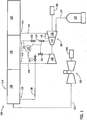
- steam conduits 112 include an HP superheated steam conduit 138 that couples HP superheater section 126 in flow communication with HP section 132.
- Steam conduits 112 also include a cold reheat (CRH) steam conduit 140 that couples HP section 132 in flow communication with RH/IP section 128.
- Steam conduits 112 further include a hot reheat (HRH) steam conduit 142 that couples RH/IP section 128 in flow communication with IP section 134.
- Steam conduits 112 also include an LP steam conduit 144 that couples LP section 130 in flow communication with LP section 136.
- steam turbine 104 includes a steam cross-over conduit 145 coupling IP section 134 in flow communication with LP section 136.
- Combined cycle power system 100 further includes a main control valve (MCV) 151 and a main stop valve (MSV) 152 positioned in HP superheated steam conduit 138 just upstream of HP section 132.
- System 100 also includes an intermediate control valve (ICV) 153 and an intermediate stop valve (ISV) 154 positioned in HRH steam conduit 142 just upstream of IP section 134.
- System 100 further includes an HP bypass valve 156 positioned within HP bypass conduit 148, and an IP bypass valve 158 positioned within IP bypass conduit 150. While MSV 152 and MCV 151 are schematically shown as two independent valves, MSV 152 and MCV 151 are positioned within a common valve body (not shown in FIG. 1 ).
- combined cycle power system 100 includes a controller 174 operatively coupled to MSV 152, MCV 151, ISV 154, and ICV 153.
- combined cycle power system 100 may include any number of controllers operatively coupled to any valves that enable operation of combined cycle power system 100 as described herein.
- Controller 174 facilitates operative control features of MSV 152, MCV 151, ISV 154, and ICV 153 via features that include, without limitation, receiving permissive inputs, transmitting permissive outputs, and transmitting opening and closing commands.
- controller 174 includes and/or is implemented by at least one processor (not shown).
- the processor includes any suitable programmable circuit such as, without limitation, one or more systems and microcontrollers, microprocessors, a general purpose central processing unit (CPU), reduced instruction set circuits (RISC), application specific integrated circuits (ASIC), programmable logic circuits (PLC), field programmable gate arrays (FPGA), and/or any other circuit capable of executing the functions described herein.
- CPU central processing unit
- RISC reduced instruction set circuits
- ASIC application specific integrated circuits
- PLC programmable logic circuits
- FPGA field programmable gate arrays
- controller 174 includes at least one memory device (not shown) coupled to the processor that stores computer-executable instructions and data, such as operating data, parameters, setpoints, threshold values, and/or any other data that enables combined cycle power system 100 to function as described herein.
- the memory device may include one or more tangible, non-transitory, computer readable media, such as, without limitation, random access memory (RAM), dynamic random access memory (DRAM), static random access memory (SRAM), a solid state disk, a hard disk, read-only memory (ROM), erasable programmable ROM (EPROM), electrically erasable programmable ROM (EEPROM), and/or non-volatile RAM (NVRAM) memory.
- RAM random access memory
- DRAM dynamic random access memory
- SRAM static random access memory
- ROM read-only memory
- EPROM erasable programmable ROM
- EEPROM electrically erasable programmable ROM
- NVRAM non-volatile RAM
- non-transitory computer-readable media includes all tangible, computer-readable media, such as a firmware, physical and virtual storage, CD-ROMs, DVDs and another digital sources such as a network or the Internet, as well as yet to be developed digital means, with the sole exception being a transitory, propagating signal.
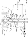
- stop valve stem assembly 214 includes a valve stem 218 and a back-seating ring 220 coupled to valve stem 218.
- Stop valve stem assembly 214 also includes a bushing 222 coupled to valve stem 218 and back-seating ring 220, wherein bushing 222 extends about valve stem 218.
- Stop valve stem assembly 214 further includes a shroud device, i.e., a pressure seal head 224 coupled to and extending about back-seating ring 220, bushing 222, and valve stem 218.
- Valve stem 218 includes a valve stem wall 226 that defines a valve stem wall outer surface 228.
- Second portion 258 of passage 252 is drilled such that a predetermined thickness T of pressure seal head wall 236 between pressure seal head wall outer surface 238 and second portion 258 of passage 252 is maintained.
- second portion 258 may be drilled to extend through pressure seal head wall 236 to outer surface 238 and material is replaced to close wall 236 and define thickness T within wall 236 via methods that include, without limitation, brazing, seal-welding, and plug insertion.
- Proximate to second portion 258 of passage 252 is a predetermined erosion site 260, wherein thickness T has any value that enables operation of valve monitoring system 250 as described herein.
- Erosion site 260 is oriented and configured to erode within a predetermined range of erosion rates for a predetermined range of solid particle concentrations in the fluid channeled through combined steam turbine stop and control valve 200.
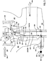
- valve monitoring system 450 Operation of valve monitoring system 450 is similar to operation of system 250 with the exception that once sufficient material is removed such that the value of thickness T approaches zero, a second opening 468 is defined at second portion 458 of machined passage 452 at erosion site 460.
- Machined passage 452 is pressurized with steam and steam leakage 464 is channeled to sensing device 462 through second opening 468, machined passage 452, and first opening 456.
- steam leakage 464 is channeled to sensing device 462 through second opening 468, machined passage 452, and first opening 456.
- a signal' (not shown) representative of an increase in steam within machined passage 452 is transmitted through channel 463 such that an alarm and/or warning indication (not shown) is annunciated to an operator (not shown). Therefore, a maintenance work order to inspect and/or repair combined steam turbine stop and control valve 200 may be generated.
Landscapes
- Engineering & Computer Science (AREA)
- General Engineering & Computer Science (AREA)
- Mechanical Engineering (AREA)
- Physics & Mathematics (AREA)
- Fluid Mechanics (AREA)
- General Physics & Mathematics (AREA)
- Control Of Turbines (AREA)
- Lift Valve (AREA)
- Details Of Valves (AREA)
- Indication Of The Valve Opening Or Closing Status (AREA)
Applications Claiming Priority (2)
| Application Number | Priority Date | Filing Date | Title |
|---|---|---|---|
| US13/566,055 US8985143B2 (en) | 2012-08-03 | 2012-08-03 | Apparatus for monitoring of valves and method of operating the same |
| PCT/US2013/053137 WO2014022621A1 (en) | 2012-08-03 | 2013-08-01 | Apparatus for monitoring of valves and methods of operating the same |
Publications (2)
| Publication Number | Publication Date |
|---|---|
| EP2880414A1 EP2880414A1 (en) | 2015-06-10 |
| EP2880414B1 true EP2880414B1 (en) | 2016-05-11 |
Family
ID=48998705
Family Applications (1)
| Application Number | Title | Priority Date | Filing Date |
|---|---|---|---|
| EP13750429.6A Active EP2880414B1 (en) | 2012-08-03 | 2013-08-01 | Apparatus for monitoring of valves and methods of operating the same |
Country Status (6)
| Country | Link |
|---|---|
| US (1) | US8985143B2 (enExample) |
| EP (1) | EP2880414B1 (enExample) |
| JP (1) | JP6183971B2 (enExample) |
| CN (1) | CN104685334B (enExample) |
| RU (1) | RU2613771C2 (enExample) |
| WO (1) | WO2014022621A1 (enExample) |
Cited By (1)
| Publication number | Priority date | Publication date | Assignee | Title |
|---|---|---|---|---|
| EP3604745B1 (en) * | 2018-08-01 | 2024-10-16 | General Electric Technology GmbH | Erosion resistant steam valve |
Families Citing this family (6)
| Publication number | Priority date | Publication date | Assignee | Title |
|---|---|---|---|---|
| US9683454B1 (en) | 2016-06-29 | 2017-06-20 | General Electric Company | Method and system for monitoring non-rotating turbomachine parts |
| US20180058255A1 (en) * | 2016-08-31 | 2018-03-01 | General Electric Technology Gmbh | Guide Condition Assessment Module For A Valve And Actuator Monitoring System |
| US10066501B2 (en) * | 2016-08-31 | 2018-09-04 | General Electric Technology Gmbh | Solid particle erosion indicator module for a valve and actuator monitoring system |
| TWI651043B (zh) * | 2017-09-21 | 2019-02-11 | 華碩電腦股份有限公司 | 信號傳輸組件 |
| US10704702B2 (en) * | 2018-06-01 | 2020-07-07 | Saudi Arabian Oil Company | Choke valve with internal sleeve for erosion protection |
| CN109916569B (zh) * | 2019-04-11 | 2020-06-05 | 重庆大学 | 密封性能试验系统 |
Family Cites Families (25)
| Publication number | Priority date | Publication date | Assignee | Title |
|---|---|---|---|---|
| US3141685A (en) * | 1960-10-11 | 1964-07-21 | Gray Tool Co | Coupling with leak detecting means and sealing ring therefor |
| US3892382A (en) * | 1973-06-22 | 1975-07-01 | Westinghouse Electric Corp | Holding arrangement for a main valve plug and a pilot valve plug |
| US4019371A (en) * | 1976-01-28 | 1977-04-26 | Exxon Production Research Company | Apparatus and method for externally testing conduit connections |
| US4410186A (en) * | 1982-04-12 | 1983-10-18 | Petroleum Designers, Inc. | Sealing system for pressurized flanged joints |
| US4615734A (en) | 1984-03-12 | 1986-10-07 | General Electric Company | Solid particle erosion resistant coating utilizing titanium carbide, process for applying and article coated therewith |
| US4704336A (en) | 1984-03-12 | 1987-11-03 | General Electric Company | Solid particle erosion resistant coating utilizing titanium carbide |
| JPS61133170U (enExample) * | 1985-02-07 | 1986-08-20 | ||
| US4776765A (en) | 1985-07-29 | 1988-10-11 | General Electric Company | Means and method for reducing solid particle erosion in turbines |
| US4726813A (en) | 1987-03-16 | 1988-02-23 | Westinghouse Electric Corp. | Solid particle magnetic deflection system for protection of steam turbine plants |
| JPS6477704A (en) * | 1987-09-18 | 1989-03-23 | Toshiba Corp | Steam valve malfunction detector |
| US4874007A (en) * | 1989-01-12 | 1989-10-17 | Taylor Julian S | Restrictor valve flow passage pop-up wear indicator |
| US4986309A (en) | 1989-08-31 | 1991-01-22 | Dayton Power And Light Company | Main steam by-pass valve |
| US5683226A (en) | 1996-05-17 | 1997-11-04 | Clark; Eugene V. | Steam turbine components with differentially coated surfaces |
| DE69725441T2 (de) * | 1996-07-03 | 2004-07-22 | Codelast Ltd., Mansfield | Dichtung |
| US5948971A (en) * | 1996-07-17 | 1999-09-07 | Texaco Inc. | Corrosion monitoring system |
| US5823224A (en) | 1997-06-26 | 1998-10-20 | Brifer International Ltd. | Slide valve |
| JP2000104504A (ja) * | 1998-09-25 | 2000-04-11 | Hitachi Ltd | 蒸気加減弁 |
| JP2000171386A (ja) * | 1998-12-08 | 2000-06-23 | Hitachi Ltd | 腐食センサ |
| EP1217352A1 (de) | 2000-12-20 | 2002-06-26 | ABBPATENT GmbH | Verfahren und Einrichtung zur Ermittlung von Leckagen an der Dichtung eines Ventils |
| RU2190839C1 (ru) * | 2001-10-15 | 2002-10-10 | ДАО "Оргэнергогаз" | Способ оценки технического состояния и остаточного ресурса пневмогидравлических агрегатов |
| US7571057B2 (en) | 2005-09-16 | 2009-08-04 | General Electric Company | System and method for monitoring degradation |
| US7296964B2 (en) | 2005-09-27 | 2007-11-20 | General Electric Company | Apparatus and methods for minimizing solid particle erosion in steam turbines |
| US20070068225A1 (en) * | 2005-09-29 | 2007-03-29 | Brown Gregory C | Leak detector for process valve |
| DE112006003471B4 (de) | 2006-01-18 | 2017-02-09 | Mitsubishi Heavy Industries, Ltd. | Feststoffteilchenerosionsbeständige Beschichtung und damit behandelte rotierende Maschine |
| US8474474B2 (en) | 2009-07-10 | 2013-07-02 | Fisher Controls International Llc | Control valve having pressure boundary integrity diagnostic capabilities, method of making the control valve, and method of using the control valve |
-
2012
- 2012-08-03 US US13/566,055 patent/US8985143B2/en active Active
-
2013
- 2013-08-01 WO PCT/US2013/053137 patent/WO2014022621A1/en not_active Ceased
- 2013-08-01 JP JP2015525578A patent/JP6183971B2/ja active Active
- 2013-08-01 RU RU2015103110A patent/RU2613771C2/ru not_active IP Right Cessation
- 2013-08-01 EP EP13750429.6A patent/EP2880414B1/en active Active
- 2013-08-01 CN CN201380051878.1A patent/CN104685334B/zh active Active
Non-Patent Citations (1)
| Title |
|---|
| None * |
Cited By (1)
| Publication number | Priority date | Publication date | Assignee | Title |
|---|---|---|---|---|
| EP3604745B1 (en) * | 2018-08-01 | 2024-10-16 | General Electric Technology GmbH | Erosion resistant steam valve |
Also Published As
| Publication number | Publication date |
|---|---|
| RU2613771C2 (ru) | 2017-03-21 |
| JP2015523529A (ja) | 2015-08-13 |
| US8985143B2 (en) | 2015-03-24 |
| CN104685334B (zh) | 2018-02-16 |
| WO2014022621A1 (en) | 2014-02-06 |
| EP2880414A1 (en) | 2015-06-10 |
| JP6183971B2 (ja) | 2017-08-23 |
| CN104685334A (zh) | 2015-06-03 |
| RU2015103110A (ru) | 2016-09-27 |
| US20140034158A1 (en) | 2014-02-06 |
Similar Documents
| Publication | Publication Date | Title |
|---|---|---|
| EP2880414B1 (en) | Apparatus for monitoring of valves and methods of operating the same | |
| JP5916431B2 (ja) | 発電プラントおよびその運転方法 | |
| CN203811327U (zh) | 阀门内漏在线监测装置 | |
| CN111537257A (zh) | 一种在线检测水轮发电机空气冷却器异常方法 | |
| CN107420628B (zh) | 一种蒸汽阀门内漏监测装置及监测方法 | |
| JP5148535B2 (ja) | 蒸気タービン装置 | |
| US6910364B2 (en) | Diagnosis method for detecting ageing symptoms in a steam turbine | |
| US20090125206A1 (en) | Automatic detection and notification of turbine internal component degradation | |
| CN104965496B (zh) | 基于防喘振控制系统的防喘振控制方法 | |
| JP3984218B2 (ja) | パイプラインの異常検出方法およびその装置 | |
| JP4554634B2 (ja) | フランジ結合部材およびそれを使用したパイプラインの異常検出装置 | |
| Addel-Geliel et al. | Application of model based fault detection for an industrial boiler | |
| JP2015078618A (ja) | 蒸気弁装置 | |
| JP6067539B2 (ja) | タービン保護装置およびその診断方法 | |
| JP2018132037A (ja) | タービン翼摩耗監視装置及びタービン翼摩耗監視方法 | |
| RU2642708C1 (ru) | Паровая энергетическая установка с трубопроводом шпиндельного пара утечки | |
| JP2017162327A (ja) | 配管系統における影響度表示システム及び影響度表示方法 | |
| CN108386724B (zh) | 防止水电站压力钢管共振的装置 | |
| CN214372824U (zh) | 孔板阀性能在线监测装置 | |
| US9334758B2 (en) | Steam turbine moisture removal system | |
| CN107060913A (zh) | 一种无人值守自动疏水系统 | |
| CN114856865A (zh) | 液体火箭发动机试车膜盒式端面密封故障监测方法 | |
| CN107689257A (zh) | 一种用于解决核电厂蒸汽管道冲蚀的支管连接系统 | |
| CN207131454U (zh) | 一种无人值守自动疏水系统 | |
| Piyushsinh | Application of monitoring approaches on steam turbine of thermal power plant for better performance |
Legal Events
| Date | Code | Title | Description |
|---|---|---|---|
| PUAI | Public reference made under article 153(3) epc to a published international application that has entered the european phase |
Free format text: ORIGINAL CODE: 0009012 |
|
| 17P | Request for examination filed |
Effective date: 20150303 |
|
| AK | Designated contracting states |
Kind code of ref document: A1 Designated state(s): AL AT BE BG CH CY CZ DE DK EE ES FI FR GB GR HR HU IE IS IT LI LT LU LV MC MK MT NL NO PL PT RO RS SE SI SK SM TR |
|
| AX | Request for extension of the european patent |
Extension state: BA ME |
|
| DAX | Request for extension of the european patent (deleted) | ||
| REG | Reference to a national code |
Ref country code: DE Ref legal event code: R079 Ref document number: 602013007469 Country of ref document: DE Free format text: PREVIOUS MAIN CLASS: G01M0003280000 Ipc: F16K0041000000 |
|
| GRAP | Despatch of communication of intention to grant a patent |
Free format text: ORIGINAL CODE: EPIDOSNIGR1 |
|
| RIC1 | Information provided on ipc code assigned before grant |
Ipc: F16K 1/12 20060101ALI20151111BHEP Ipc: G01M 3/28 20060101ALI20151111BHEP Ipc: F16K 41/00 20060101AFI20151111BHEP Ipc: F01D 21/00 20060101ALI20151111BHEP Ipc: F01D 17/02 20060101ALI20151111BHEP Ipc: F01D 21/14 20060101ALI20151111BHEP Ipc: F16K 37/00 20060101ALI20151111BHEP |
|
| INTG | Intention to grant announced |
Effective date: 20151203 |
|
| GRAS | Grant fee paid |
Free format text: ORIGINAL CODE: EPIDOSNIGR3 |
|
| GRAJ | Information related to disapproval of communication of intention to grant by the applicant or resumption of examination proceedings by the epo deleted |
Free format text: ORIGINAL CODE: EPIDOSDIGR1 |
|
| GRAL | Information related to payment of fee for publishing/printing deleted |
Free format text: ORIGINAL CODE: EPIDOSDIGR3 |
|
| GRAP | Despatch of communication of intention to grant a patent |
Free format text: ORIGINAL CODE: EPIDOSNIGR1 |
|
| GRAR | Information related to intention to grant a patent recorded |
Free format text: ORIGINAL CODE: EPIDOSNIGR71 |
|
| GRAA | (expected) grant |
Free format text: ORIGINAL CODE: 0009210 |
|
| INTG | Intention to grant announced |
Effective date: 20160329 |
|
| AK | Designated contracting states |
Kind code of ref document: B1 Designated state(s): AL AT BE BG CH CY CZ DE DK EE ES FI FR GB GR HR HU IE IS IT LI LT LU LV MC MK MT NL NO PL PT RO RS SE SI SK SM TR |
|
| REG | Reference to a national code |
Ref country code: GB Ref legal event code: FG4D |
|
| REG | Reference to a national code |
Ref country code: CH Ref legal event code: EP |
|
| REG | Reference to a national code |
Ref country code: AT Ref legal event code: REF Ref document number: 798938 Country of ref document: AT Kind code of ref document: T Effective date: 20160515 |
|
| REG | Reference to a national code |
Ref country code: IE Ref legal event code: FG4D |
|
| REG | Reference to a national code |
Ref country code: DE Ref legal event code: R096 Ref document number: 602013007469 Country of ref document: DE |
|
| REG | Reference to a national code |
Ref country code: LT Ref legal event code: MG4D |
|
| REG | Reference to a national code |
Ref country code: NL Ref legal event code: MP Effective date: 20160511 |
|
| PG25 | Lapsed in a contracting state [announced via postgrant information from national office to epo] |
Ref country code: NO Free format text: LAPSE BECAUSE OF FAILURE TO SUBMIT A TRANSLATION OF THE DESCRIPTION OR TO PAY THE FEE WITHIN THE PRESCRIBED TIME-LIMIT Effective date: 20160811 Ref country code: FI Free format text: LAPSE BECAUSE OF FAILURE TO SUBMIT A TRANSLATION OF THE DESCRIPTION OR TO PAY THE FEE WITHIN THE PRESCRIBED TIME-LIMIT Effective date: 20160511 Ref country code: NL Free format text: LAPSE BECAUSE OF FAILURE TO SUBMIT A TRANSLATION OF THE DESCRIPTION OR TO PAY THE FEE WITHIN THE PRESCRIBED TIME-LIMIT Effective date: 20160511 Ref country code: LT Free format text: LAPSE BECAUSE OF FAILURE TO SUBMIT A TRANSLATION OF THE DESCRIPTION OR TO PAY THE FEE WITHIN THE PRESCRIBED TIME-LIMIT Effective date: 20160511 |
|
| REG | Reference to a national code |
Ref country code: AT Ref legal event code: MK05 Ref document number: 798938 Country of ref document: AT Kind code of ref document: T Effective date: 20160511 |
|
| PG25 | Lapsed in a contracting state [announced via postgrant information from national office to epo] |
Ref country code: ES Free format text: LAPSE BECAUSE OF FAILURE TO SUBMIT A TRANSLATION OF THE DESCRIPTION OR TO PAY THE FEE WITHIN THE PRESCRIBED TIME-LIMIT Effective date: 20160511 Ref country code: SE Free format text: LAPSE BECAUSE OF FAILURE TO SUBMIT A TRANSLATION OF THE DESCRIPTION OR TO PAY THE FEE WITHIN THE PRESCRIBED TIME-LIMIT Effective date: 20160511 Ref country code: GR Free format text: LAPSE BECAUSE OF FAILURE TO SUBMIT A TRANSLATION OF THE DESCRIPTION OR TO PAY THE FEE WITHIN THE PRESCRIBED TIME-LIMIT Effective date: 20160812 Ref country code: LV Free format text: LAPSE BECAUSE OF FAILURE TO SUBMIT A TRANSLATION OF THE DESCRIPTION OR TO PAY THE FEE WITHIN THE PRESCRIBED TIME-LIMIT Effective date: 20160511 Ref country code: PT Free format text: LAPSE BECAUSE OF FAILURE TO SUBMIT A TRANSLATION OF THE DESCRIPTION OR TO PAY THE FEE WITHIN THE PRESCRIBED TIME-LIMIT Effective date: 20160912 Ref country code: HR Free format text: LAPSE BECAUSE OF FAILURE TO SUBMIT A TRANSLATION OF THE DESCRIPTION OR TO PAY THE FEE WITHIN THE PRESCRIBED TIME-LIMIT Effective date: 20160511 Ref country code: RS Free format text: LAPSE BECAUSE OF FAILURE TO SUBMIT A TRANSLATION OF THE DESCRIPTION OR TO PAY THE FEE WITHIN THE PRESCRIBED TIME-LIMIT Effective date: 20160511 |
|
| PG25 | Lapsed in a contracting state [announced via postgrant information from national office to epo] |
Ref country code: BE Free format text: LAPSE BECAUSE OF NON-PAYMENT OF DUE FEES Effective date: 20160831 |
|
| PG25 | Lapsed in a contracting state [announced via postgrant information from national office to epo] |
Ref country code: DK Free format text: LAPSE BECAUSE OF FAILURE TO SUBMIT A TRANSLATION OF THE DESCRIPTION OR TO PAY THE FEE WITHIN THE PRESCRIBED TIME-LIMIT Effective date: 20160511 Ref country code: RO Free format text: LAPSE BECAUSE OF FAILURE TO SUBMIT A TRANSLATION OF THE DESCRIPTION OR TO PAY THE FEE WITHIN THE PRESCRIBED TIME-LIMIT Effective date: 20160511 Ref country code: EE Free format text: LAPSE BECAUSE OF FAILURE TO SUBMIT A TRANSLATION OF THE DESCRIPTION OR TO PAY THE FEE WITHIN THE PRESCRIBED TIME-LIMIT Effective date: 20160511 Ref country code: SK Free format text: LAPSE BECAUSE OF FAILURE TO SUBMIT A TRANSLATION OF THE DESCRIPTION OR TO PAY THE FEE WITHIN THE PRESCRIBED TIME-LIMIT Effective date: 20160511 Ref country code: CZ Free format text: LAPSE BECAUSE OF FAILURE TO SUBMIT A TRANSLATION OF THE DESCRIPTION OR TO PAY THE FEE WITHIN THE PRESCRIBED TIME-LIMIT Effective date: 20160511 |
|
| REG | Reference to a national code |
Ref country code: DE Ref legal event code: R097 Ref document number: 602013007469 Country of ref document: DE |
|
| PG25 | Lapsed in a contracting state [announced via postgrant information from national office to epo] |
Ref country code: BE Free format text: LAPSE BECAUSE OF FAILURE TO SUBMIT A TRANSLATION OF THE DESCRIPTION OR TO PAY THE FEE WITHIN THE PRESCRIBED TIME-LIMIT Effective date: 20160511 Ref country code: SM Free format text: LAPSE BECAUSE OF FAILURE TO SUBMIT A TRANSLATION OF THE DESCRIPTION OR TO PAY THE FEE WITHIN THE PRESCRIBED TIME-LIMIT Effective date: 20160511 Ref country code: PL Free format text: LAPSE BECAUSE OF FAILURE TO SUBMIT A TRANSLATION OF THE DESCRIPTION OR TO PAY THE FEE WITHIN THE PRESCRIBED TIME-LIMIT Effective date: 20160511 Ref country code: AT Free format text: LAPSE BECAUSE OF FAILURE TO SUBMIT A TRANSLATION OF THE DESCRIPTION OR TO PAY THE FEE WITHIN THE PRESCRIBED TIME-LIMIT Effective date: 20160511 |
|
| PLBE | No opposition filed within time limit |
Free format text: ORIGINAL CODE: 0009261 |
|
| STAA | Information on the status of an ep patent application or granted ep patent |
Free format text: STATUS: NO OPPOSITION FILED WITHIN TIME LIMIT |
|
| PG25 | Lapsed in a contracting state [announced via postgrant information from national office to epo] |
Ref country code: MC Free format text: LAPSE BECAUSE OF FAILURE TO SUBMIT A TRANSLATION OF THE DESCRIPTION OR TO PAY THE FEE WITHIN THE PRESCRIBED TIME-LIMIT Effective date: 20160511 |
|
| 26N | No opposition filed |
Effective date: 20170214 |
|
| REG | Reference to a national code |
Ref country code: FR Ref legal event code: ST Effective date: 20170428 |
|
| PG25 | Lapsed in a contracting state [announced via postgrant information from national office to epo] |
Ref country code: SI Free format text: LAPSE BECAUSE OF FAILURE TO SUBMIT A TRANSLATION OF THE DESCRIPTION OR TO PAY THE FEE WITHIN THE PRESCRIBED TIME-LIMIT Effective date: 20160511 |
|
| REG | Reference to a national code |
Ref country code: IE Ref legal event code: MM4A |
|
| PG25 | Lapsed in a contracting state [announced via postgrant information from national office to epo] |
Ref country code: FR Free format text: LAPSE BECAUSE OF NON-PAYMENT OF DUE FEES Effective date: 20160831 Ref country code: IE Free format text: LAPSE BECAUSE OF NON-PAYMENT OF DUE FEES Effective date: 20160801 |
|
| PG25 | Lapsed in a contracting state [announced via postgrant information from national office to epo] |
Ref country code: LU Free format text: LAPSE BECAUSE OF NON-PAYMENT OF DUE FEES Effective date: 20160801 |
|
| PGFP | Annual fee paid to national office [announced via postgrant information from national office to epo] |
Ref country code: CH Payment date: 20170827 Year of fee payment: 5 |
|
| GBPC | Gb: european patent ceased through non-payment of renewal fee |
Effective date: 20170801 |
|
| PG25 | Lapsed in a contracting state [announced via postgrant information from national office to epo] |
Ref country code: HU Free format text: LAPSE BECAUSE OF FAILURE TO SUBMIT A TRANSLATION OF THE DESCRIPTION OR TO PAY THE FEE WITHIN THE PRESCRIBED TIME-LIMIT; INVALID AB INITIO Effective date: 20130801 |
|
| PG25 | Lapsed in a contracting state [announced via postgrant information from national office to epo] |
Ref country code: CY Free format text: LAPSE BECAUSE OF FAILURE TO SUBMIT A TRANSLATION OF THE DESCRIPTION OR TO PAY THE FEE WITHIN THE PRESCRIBED TIME-LIMIT Effective date: 20160511 Ref country code: IS Free format text: LAPSE BECAUSE OF FAILURE TO SUBMIT A TRANSLATION OF THE DESCRIPTION OR TO PAY THE FEE WITHIN THE PRESCRIBED TIME-LIMIT Effective date: 20160511 Ref country code: MK Free format text: LAPSE BECAUSE OF FAILURE TO SUBMIT A TRANSLATION OF THE DESCRIPTION OR TO PAY THE FEE WITHIN THE PRESCRIBED TIME-LIMIT Effective date: 20160511 Ref country code: MT Free format text: LAPSE BECAUSE OF NON-PAYMENT OF DUE FEES Effective date: 20160831 |
|
| PG25 | Lapsed in a contracting state [announced via postgrant information from national office to epo] |
Ref country code: BG Free format text: LAPSE BECAUSE OF FAILURE TO SUBMIT A TRANSLATION OF THE DESCRIPTION OR TO PAY THE FEE WITHIN THE PRESCRIBED TIME-LIMIT Effective date: 20160511 Ref country code: GB Free format text: LAPSE BECAUSE OF NON-PAYMENT OF DUE FEES Effective date: 20170801 |
|
| PG25 | Lapsed in a contracting state [announced via postgrant information from national office to epo] |
Ref country code: TR Free format text: LAPSE BECAUSE OF FAILURE TO SUBMIT A TRANSLATION OF THE DESCRIPTION OR TO PAY THE FEE WITHIN THE PRESCRIBED TIME-LIMIT Effective date: 20160511 Ref country code: AL Free format text: LAPSE BECAUSE OF FAILURE TO SUBMIT A TRANSLATION OF THE DESCRIPTION OR TO PAY THE FEE WITHIN THE PRESCRIBED TIME-LIMIT Effective date: 20160511 |
|
| REG | Reference to a national code |
Ref country code: CH Ref legal event code: PL |
|
| PG25 | Lapsed in a contracting state [announced via postgrant information from national office to epo] |
Ref country code: LI Free format text: LAPSE BECAUSE OF NON-PAYMENT OF DUE FEES Effective date: 20180831 Ref country code: CH Free format text: LAPSE BECAUSE OF NON-PAYMENT OF DUE FEES Effective date: 20180831 |
|
| PGFP | Annual fee paid to national office [announced via postgrant information from national office to epo] |
Ref country code: IT Payment date: 20190722 Year of fee payment: 7 |
|
| PG25 | Lapsed in a contracting state [announced via postgrant information from national office to epo] |
Ref country code: IT Free format text: LAPSE BECAUSE OF NON-PAYMENT OF DUE FEES Effective date: 20200801 |
|
| P01 | Opt-out of the competence of the unified patent court (upc) registered |
Effective date: 20230522 |
|
| REG | Reference to a national code |
Ref country code: DE Ref legal event code: R081 Ref document number: 602013007469 Country of ref document: DE Owner name: GENERAL ELECTRIC TECHNOLOGY GMBH, CH Free format text: FORMER OWNER: GENERAL ELECTRIC COMPANY, SCHENECTADY, NY, US |
|
| PGFP | Annual fee paid to national office [announced via postgrant information from national office to epo] |
Ref country code: DE Payment date: 20250724 Year of fee payment: 13 |