EP2880342B1 - Ventil mit einem lastvariierenden mechanismus und betriebsverfahren dafür - Google Patents
Ventil mit einem lastvariierenden mechanismus und betriebsverfahren dafür Download PDFInfo
- Publication number
- EP2880342B1 EP2880342B1 EP13828457.5A EP13828457A EP2880342B1 EP 2880342 B1 EP2880342 B1 EP 2880342B1 EP 13828457 A EP13828457 A EP 13828457A EP 2880342 B1 EP2880342 B1 EP 2880342B1
- Authority
- EP
- European Patent Office
- Prior art keywords
- valve
- rotor
- load force
- valve element
- sealing
- Prior art date
- Legal status (The legal status is an assumption and is not a legal conclusion. Google has not performed a legal analysis and makes no representation as to the accuracy of the status listed.)
- Not-in-force
Links
- 238000000034 method Methods 0.000 title claims description 67
- 230000007246 mechanism Effects 0.000 title description 44
- 238000007789 sealing Methods 0.000 claims description 100
- 239000012530 fluid Substances 0.000 claims description 60
- 230000008569 process Effects 0.000 claims description 30
- 238000004891 communication Methods 0.000 claims description 19
- 230000002829 reductive effect Effects 0.000 claims description 16
- 230000005465 channeling Effects 0.000 claims 1
- 238000012856 packing Methods 0.000 description 21
- 239000000463 material Substances 0.000 description 19
- 230000003068 static effect Effects 0.000 description 18
- 238000010926 purge Methods 0.000 description 9
- 238000004140 cleaning Methods 0.000 description 8
- 230000006835 compression Effects 0.000 description 8
- 238000007906 compression Methods 0.000 description 8
- 230000008901 benefit Effects 0.000 description 7
- 238000001125 extrusion Methods 0.000 description 4
- 239000007788 liquid Substances 0.000 description 4
- 239000002245 particle Substances 0.000 description 4
- 238000003825 pressing Methods 0.000 description 4
- 238000012546 transfer Methods 0.000 description 4
- OKTJSMMVPCPJKN-UHFFFAOYSA-N Carbon Chemical compound [C] OKTJSMMVPCPJKN-UHFFFAOYSA-N 0.000 description 3
- 239000004696 Poly ether ether ketone Substances 0.000 description 3
- 239000004734 Polyphenylene sulfide Substances 0.000 description 3
- 229910052799 carbon Inorganic materials 0.000 description 3
- 230000007423 decrease Effects 0.000 description 3
- 229920002530 polyetherether ketone Polymers 0.000 description 3
- 229920000642 polymer Polymers 0.000 description 3
- 229920000069 polyphenylene sulfide Polymers 0.000 description 3
- 238000005406 washing Methods 0.000 description 3
- -1 Polymide Polymers 0.000 description 2
- 229920006362 Teflon® Polymers 0.000 description 2
- NRTOMJZYCJJWKI-UHFFFAOYSA-N Titanium nitride Chemical compound [Ti]#N NRTOMJZYCJJWKI-UHFFFAOYSA-N 0.000 description 2
- 238000004458 analytical method Methods 0.000 description 2
- CXOWYMLTGOFURZ-UHFFFAOYSA-N azanylidynechromium Chemical compound [Cr]#N CXOWYMLTGOFURZ-UHFFFAOYSA-N 0.000 description 2
- 238000011109 contamination Methods 0.000 description 2
- 230000003247 decreasing effect Effects 0.000 description 2
- 230000001419 dependent effect Effects 0.000 description 2
- 229920002313 fluoropolymer Polymers 0.000 description 2
- 238000012986 modification Methods 0.000 description 2
- 230000004048 modification Effects 0.000 description 2
- 238000012544 monitoring process Methods 0.000 description 2
- 229920001343 polytetrafluoroethylene Polymers 0.000 description 2
- 239000004810 polytetrafluoroethylene Substances 0.000 description 2
- WFKWXMTUELFFGS-UHFFFAOYSA-N tungsten Chemical compound [W] WFKWXMTUELFFGS-UHFFFAOYSA-N 0.000 description 2
- 238000001195 ultra high performance liquid chromatography Methods 0.000 description 2
- 229910052582 BN Inorganic materials 0.000 description 1
- PZNSFCLAULLKQX-UHFFFAOYSA-N Boron nitride Chemical compound N#B PZNSFCLAULLKQX-UHFFFAOYSA-N 0.000 description 1
- 239000004215 Carbon black (E152) Substances 0.000 description 1
- 229920006169 Perfluoroelastomer Polymers 0.000 description 1
- 239000004809 Teflon Substances 0.000 description 1
- 230000000903 blocking effect Effects 0.000 description 1
- 239000012159 carrier gas Substances 0.000 description 1
- 230000008859 change Effects 0.000 description 1
- 239000011248 coating agent Substances 0.000 description 1
- 238000000576 coating method Methods 0.000 description 1
- 238000010276 construction Methods 0.000 description 1
- 238000013461 design Methods 0.000 description 1
- 230000000694 effects Effects 0.000 description 1
- 238000005516 engineering process Methods 0.000 description 1
- 239000004811 fluoropolymer Substances 0.000 description 1
- 239000007789 gas Substances 0.000 description 1
- 238000004817 gas chromatography Methods 0.000 description 1
- 229930195733 hydrocarbon Natural products 0.000 description 1
- 150000002430 hydrocarbons Chemical class 0.000 description 1
- 238000002347 injection Methods 0.000 description 1
- 239000007924 injection Substances 0.000 description 1
- 230000010354 integration Effects 0.000 description 1
- 230000000670 limiting effect Effects 0.000 description 1
- 238000004811 liquid chromatography Methods 0.000 description 1
- 230000013011 mating Effects 0.000 description 1
- 230000036961 partial effect Effects 0.000 description 1
- 229920003223 poly(pyromellitimide-1,4-diphenyl ether) Polymers 0.000 description 1
- 230000002028 premature Effects 0.000 description 1
- 230000009467 reduction Effects 0.000 description 1
- 239000002904 solvent Substances 0.000 description 1
- 229910001220 stainless steel Inorganic materials 0.000 description 1
- 239000010935 stainless steel Substances 0.000 description 1
Images










Classifications
-
- F—MECHANICAL ENGINEERING; LIGHTING; HEATING; WEAPONS; BLASTING
- F16—ENGINEERING ELEMENTS AND UNITS; GENERAL MEASURES FOR PRODUCING AND MAINTAINING EFFECTIVE FUNCTIONING OF MACHINES OR INSTALLATIONS; THERMAL INSULATION IN GENERAL
- F16K—VALVES; TAPS; COCKS; ACTUATING-FLOATS; DEVICES FOR VENTING OR AERATING
- F16K5/00—Plug valves; Taps or cocks comprising only cut-off apparatus having at least one of the sealing faces shaped as a more or less complete surface of a solid of revolution, the opening and closing movement being predominantly rotary
- F16K5/08—Details
- F16K5/14—Special arrangements for separating the sealing faces or for pressing them together
- F16K5/16—Special arrangements for separating the sealing faces or for pressing them together for plugs with conical surfaces
- F16K5/161—Special arrangements for separating the sealing faces or for pressing them together for plugs with conical surfaces with the housing or parts of the housing mechanically pressing the seal against the plug
-
- F—MECHANICAL ENGINEERING; LIGHTING; HEATING; WEAPONS; BLASTING
- F16—ENGINEERING ELEMENTS AND UNITS; GENERAL MEASURES FOR PRODUCING AND MAINTAINING EFFECTIVE FUNCTIONING OF MACHINES OR INSTALLATIONS; THERMAL INSULATION IN GENERAL
- F16K—VALVES; TAPS; COCKS; ACTUATING-FLOATS; DEVICES FOR VENTING OR AERATING
- F16K11/00—Multiple-way valves, e.g. mixing valves; Pipe fittings incorporating such valves
- F16K11/02—Multiple-way valves, e.g. mixing valves; Pipe fittings incorporating such valves with all movable sealing faces moving as one unit
- F16K11/06—Multiple-way valves, e.g. mixing valves; Pipe fittings incorporating such valves with all movable sealing faces moving as one unit comprising only sliding valves, i.e. sliding closure elements
- F16K11/072—Multiple-way valves, e.g. mixing valves; Pipe fittings incorporating such valves with all movable sealing faces moving as one unit comprising only sliding valves, i.e. sliding closure elements with pivoted closure members
- F16K11/074—Multiple-way valves, e.g. mixing valves; Pipe fittings incorporating such valves with all movable sealing faces moving as one unit comprising only sliding valves, i.e. sliding closure elements with pivoted closure members with flat sealing faces
- F16K11/0743—Multiple-way valves, e.g. mixing valves; Pipe fittings incorporating such valves with all movable sealing faces moving as one unit comprising only sliding valves, i.e. sliding closure elements with pivoted closure members with flat sealing faces with both the supply and the discharge passages being on one side of the closure plates
-
- F—MECHANICAL ENGINEERING; LIGHTING; HEATING; WEAPONS; BLASTING
- F16—ENGINEERING ELEMENTS AND UNITS; GENERAL MEASURES FOR PRODUCING AND MAINTAINING EFFECTIVE FUNCTIONING OF MACHINES OR INSTALLATIONS; THERMAL INSULATION IN GENERAL
- F16K—VALVES; TAPS; COCKS; ACTUATING-FLOATS; DEVICES FOR VENTING OR AERATING
- F16K11/00—Multiple-way valves, e.g. mixing valves; Pipe fittings incorporating such valves
- F16K11/02—Multiple-way valves, e.g. mixing valves; Pipe fittings incorporating such valves with all movable sealing faces moving as one unit
- F16K11/08—Multiple-way valves, e.g. mixing valves; Pipe fittings incorporating such valves with all movable sealing faces moving as one unit comprising only taps or cocks
- F16K11/083—Multiple-way valves, e.g. mixing valves; Pipe fittings incorporating such valves with all movable sealing faces moving as one unit comprising only taps or cocks with tapered plug
- F16K11/0833—Multiple-way valves, e.g. mixing valves; Pipe fittings incorporating such valves with all movable sealing faces moving as one unit comprising only taps or cocks with tapered plug having all the connecting conduits situated in a single plane perpendicular to the axis of the plug
-
- F—MECHANICAL ENGINEERING; LIGHTING; HEATING; WEAPONS; BLASTING
- F16—ENGINEERING ELEMENTS AND UNITS; GENERAL MEASURES FOR PRODUCING AND MAINTAINING EFFECTIVE FUNCTIONING OF MACHINES OR INSTALLATIONS; THERMAL INSULATION IN GENERAL
- F16K—VALVES; TAPS; COCKS; ACTUATING-FLOATS; DEVICES FOR VENTING OR AERATING
- F16K11/00—Multiple-way valves, e.g. mixing valves; Pipe fittings incorporating such valves
- F16K11/02—Multiple-way valves, e.g. mixing valves; Pipe fittings incorporating such valves with all movable sealing faces moving as one unit
- F16K11/08—Multiple-way valves, e.g. mixing valves; Pipe fittings incorporating such valves with all movable sealing faces moving as one unit comprising only taps or cocks
- F16K11/087—Multiple-way valves, e.g. mixing valves; Pipe fittings incorporating such valves with all movable sealing faces moving as one unit comprising only taps or cocks with spherical plug
- F16K11/0873—Multiple-way valves, e.g. mixing valves; Pipe fittings incorporating such valves with all movable sealing faces moving as one unit comprising only taps or cocks with spherical plug the plug being only rotatable around one spindle
-
- F—MECHANICAL ENGINEERING; LIGHTING; HEATING; WEAPONS; BLASTING
- F16—ENGINEERING ELEMENTS AND UNITS; GENERAL MEASURES FOR PRODUCING AND MAINTAINING EFFECTIVE FUNCTIONING OF MACHINES OR INSTALLATIONS; THERMAL INSULATION IN GENERAL
- F16K—VALVES; TAPS; COCKS; ACTUATING-FLOATS; DEVICES FOR VENTING OR AERATING
- F16K3/00—Gate valves or sliding valves, i.e. cut-off apparatus with closing members having a sliding movement along the seat for opening and closing
- F16K3/02—Gate valves or sliding valves, i.e. cut-off apparatus with closing members having a sliding movement along the seat for opening and closing with flat sealing faces; Packings therefor
- F16K3/04—Gate valves or sliding valves, i.e. cut-off apparatus with closing members having a sliding movement along the seat for opening and closing with flat sealing faces; Packings therefor with pivoted closure members
- F16K3/10—Gate valves or sliding valves, i.e. cut-off apparatus with closing members having a sliding movement along the seat for opening and closing with flat sealing faces; Packings therefor with pivoted closure members with special arrangements for separating the sealing faces or for pressing them together
-
- F—MECHANICAL ENGINEERING; LIGHTING; HEATING; WEAPONS; BLASTING
- F16—ENGINEERING ELEMENTS AND UNITS; GENERAL MEASURES FOR PRODUCING AND MAINTAINING EFFECTIVE FUNCTIONING OF MACHINES OR INSTALLATIONS; THERMAL INSULATION IN GENERAL
- F16K—VALVES; TAPS; COCKS; ACTUATING-FLOATS; DEVICES FOR VENTING OR AERATING
- F16K3/00—Gate valves or sliding valves, i.e. cut-off apparatus with closing members having a sliding movement along the seat for opening and closing
- F16K3/02—Gate valves or sliding valves, i.e. cut-off apparatus with closing members having a sliding movement along the seat for opening and closing with flat sealing faces; Packings therefor
- F16K3/16—Gate valves or sliding valves, i.e. cut-off apparatus with closing members having a sliding movement along the seat for opening and closing with flat sealing faces; Packings therefor with special arrangements for separating the sealing faces or for pressing them together
- F16K3/18—Gate valves or sliding valves, i.e. cut-off apparatus with closing members having a sliding movement along the seat for opening and closing with flat sealing faces; Packings therefor with special arrangements for separating the sealing faces or for pressing them together by movement of the closure members
-
- F—MECHANICAL ENGINEERING; LIGHTING; HEATING; WEAPONS; BLASTING
- F16—ENGINEERING ELEMENTS AND UNITS; GENERAL MEASURES FOR PRODUCING AND MAINTAINING EFFECTIVE FUNCTIONING OF MACHINES OR INSTALLATIONS; THERMAL INSULATION IN GENERAL
- F16K—VALVES; TAPS; COCKS; ACTUATING-FLOATS; DEVICES FOR VENTING OR AERATING
- F16K31/00—Actuating devices; Operating means; Releasing devices
- F16K31/44—Mechanical actuating means
- F16K31/60—Handles
- F16K31/602—Pivoting levers, e.g. single-sided
-
- F—MECHANICAL ENGINEERING; LIGHTING; HEATING; WEAPONS; BLASTING
- F16—ENGINEERING ELEMENTS AND UNITS; GENERAL MEASURES FOR PRODUCING AND MAINTAINING EFFECTIVE FUNCTIONING OF MACHINES OR INSTALLATIONS; THERMAL INSULATION IN GENERAL
- F16K—VALVES; TAPS; COCKS; ACTUATING-FLOATS; DEVICES FOR VENTING OR AERATING
- F16K37/00—Special means in or on valves or other cut-off apparatus for indicating or recording operation thereof, or for enabling an alarm to be given
- F16K37/0025—Electrical or magnetic means
- F16K37/0041—Electrical or magnetic means for measuring valve parameters
-
- F—MECHANICAL ENGINEERING; LIGHTING; HEATING; WEAPONS; BLASTING
- F16—ENGINEERING ELEMENTS AND UNITS; GENERAL MEASURES FOR PRODUCING AND MAINTAINING EFFECTIVE FUNCTIONING OF MACHINES OR INSTALLATIONS; THERMAL INSULATION IN GENERAL
- F16K—VALVES; TAPS; COCKS; ACTUATING-FLOATS; DEVICES FOR VENTING OR AERATING
- F16K5/00—Plug valves; Taps or cocks comprising only cut-off apparatus having at least one of the sealing faces shaped as a more or less complete surface of a solid of revolution, the opening and closing movement being predominantly rotary
- F16K5/08—Details
- F16K5/14—Special arrangements for separating the sealing faces or for pressing them together
- F16K5/16—Special arrangements for separating the sealing faces or for pressing them together for plugs with conical surfaces
- F16K5/162—Special arrangements for separating the sealing faces or for pressing them together for plugs with conical surfaces with the plugs or parts of the plugs mechanically pressing the seal against the housing
- F16K5/166—Means pressing on the large diameter
-
- F—MECHANICAL ENGINEERING; LIGHTING; HEATING; WEAPONS; BLASTING
- F16—ENGINEERING ELEMENTS AND UNITS; GENERAL MEASURES FOR PRODUCING AND MAINTAINING EFFECTIVE FUNCTIONING OF MACHINES OR INSTALLATIONS; THERMAL INSULATION IN GENERAL
- F16K—VALVES; TAPS; COCKS; ACTUATING-FLOATS; DEVICES FOR VENTING OR AERATING
- F16K5/00—Plug valves; Taps or cocks comprising only cut-off apparatus having at least one of the sealing faces shaped as a more or less complete surface of a solid of revolution, the opening and closing movement being predominantly rotary
- F16K5/08—Details
- F16K5/14—Special arrangements for separating the sealing faces or for pressing them together
- F16K5/20—Special arrangements for separating the sealing faces or for pressing them together for plugs with spherical surfaces
- F16K5/201—Special arrangements for separating the sealing faces or for pressing them together for plugs with spherical surfaces with the housing or parts of the housing mechanically pressing the seal against the plug
-
- G—PHYSICS
- G01—MEASURING; TESTING
- G01N—INVESTIGATING OR ANALYSING MATERIALS BY DETERMINING THEIR CHEMICAL OR PHYSICAL PROPERTIES
- G01N30/00—Investigating or analysing materials by separation into components using adsorption, absorption or similar phenomena or using ion-exchange, e.g. chromatography or field flow fractionation
- G01N30/02—Column chromatography
- G01N30/26—Conditioning of the fluid carrier; Flow patterns
- G01N30/28—Control of physical parameters of the fluid carrier
- G01N30/32—Control of physical parameters of the fluid carrier of pressure or speed
-
- G—PHYSICS
- G01—MEASURING; TESTING
- G01N—INVESTIGATING OR ANALYSING MATERIALS BY DETERMINING THEIR CHEMICAL OR PHYSICAL PROPERTIES
- G01N30/00—Investigating or analysing materials by separation into components using adsorption, absorption or similar phenomena or using ion-exchange, e.g. chromatography or field flow fractionation
- G01N30/02—Column chromatography
- G01N30/26—Conditioning of the fluid carrier; Flow patterns
- G01N30/28—Control of physical parameters of the fluid carrier
- G01N30/32—Control of physical parameters of the fluid carrier of pressure or speed
- G01N2030/328—Control of physical parameters of the fluid carrier of pressure or speed valves, e.g. check valves of pumps
-
- Y—GENERAL TAGGING OF NEW TECHNOLOGICAL DEVELOPMENTS; GENERAL TAGGING OF CROSS-SECTIONAL TECHNOLOGIES SPANNING OVER SEVERAL SECTIONS OF THE IPC; TECHNICAL SUBJECTS COVERED BY FORMER USPC CROSS-REFERENCE ART COLLECTIONS [XRACs] AND DIGESTS
- Y10—TECHNICAL SUBJECTS COVERED BY FORMER USPC
- Y10T—TECHNICAL SUBJECTS COVERED BY FORMER US CLASSIFICATION
- Y10T137/00—Fluid handling
- Y10T137/0318—Processes
Definitions
- the present invention generally concerns systems and methods related to valves and more particularly relates to a valve with a load varying mechanism and a method for reducing friction during movement of a valve element.
- valves Liquid chromatography and auto-sampler systems rely mostly on flat rotary based design valves to handle various fluids. Many different configurations are possible, such as the standard six-port injection valves, valves with syringe port or for sample stream selection, column selection, multi-position/multitask, such as loading, injecting, washing, etc. In most cases, valves have a flat rotor and a flat stator. The flat rotor is pushed against a fixed flat stator. The rotor has various grooves machined in it, allowing different stator port connection schemes to fit any particular application.
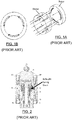
- FIG. 1A to 2 a typical six-port liquid chromatographic valve.
- the sealing i.e. the leak integrity, between two adjacent ports and all outboard leaking integrity from any port, is provided by applying a load on the rotor, such required load being greater for higher pressure operations.
- the load, or pressing force is normally set by a mechanical biasing element, such as a compression spring or a stack of Belleville discs. Since the force maintaining the rotor on the stator is relatively high, so is friction and resultant wear. Because wear occurs when the rotor is turned against the stator, the lifetime of such a valve is short. Scratches eventually appear on the rotor, which is usually made of softer material than the stator.
- Friction between the rotor and the stator causes particles to be generated, further increasing the problems associated with wear. Leaks are likely to appear, and eventually the valve will have to be repaired or replaced. This problem may be found in most flat and conical rotary valves available.
- US 6,453,946 discloses a valve in which one of the sealing surfaces is coated with Tungstene Carbide/Carbon (WC/C) while the other sealing surface is provided with a fluorocarbon polymer.
- WC/C Tungstene Carbide/Carbon
- process pressure can be as high as 20,000 PSI.
- process pressure it is meant the pressure of the fluid circulating in the valve, such as the sample gas, carrier gas or liquid mobile phase. At such a pressure level, the required rotor loading force provided by the biasing element is high, and so is friction and resultant wear.
- coating the sealing surfaces of the stator may improve the lifetime of the rotary valve, there is a still a need for an improved valve system that may allow even longer lifetime, especially for high pressure applications.
- valves are usually tuned at ambient temperature, but are mostly used at different temperatures, from cryogenic temperatures to temperatures of around 350°C.
- the behavior of ea ch part of the valve may therefore differ greatly depending on the temperature range at which it is operated. Consequently, a valve can work perfectly when tuned and operated at ambient temperature, but important leakage may occur when the valve is used in a system operated at a different temperature.
- An advantage of the present method is that friction between the sealing surfaces of the valve element and stationary body of the valve is reduced during movement of the valve element, and preferably just before the movement start-up. Reducing the friction between the sealing surfaces when the valve element is moved reduces wear and particle generation in the valve, which in turn reduces leaks and/or contamination.
- Another advantage of the method is that the load force applied on the valve element is not dependent upon the operating pressure of the valve, as in US patent 6,193,213 .
- the load varying mechanism also allows performing a cleaning/washing cycle without having to dismantle or disassemble the valve.
- a cleaning fluid can be applied to flow through the valve from a purge port, so as to clean all surfaces and grooves by moving the valve element; this intermediate cleaning load being low enough to allow a slight spacing of the valve element from the stationary body.
- This method is particularly adapted to rotary valve, in which the valve element, which is a rotor, can be rotated at high speeds.
- Another advantage of this method is that, when the valve element is stationary in an operational position, it is possible to apply a much higher load on the valve element than what is typically found in other commercially available valves, and this, without the risk of damaging the valve element. This results in a much higher sealing integrity.
- the load varying mechanism also helps to maintain the same predetermined load scheme, even if some of the characteristics of the components change over time, such as can occur when the biasing element softens or the parts of the valve thermally expand in the case of high temperature applications.
- Methods according to implementations of the invention can be used for flat, conical and ball-type rotary valves, among other possible valves.
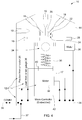
- the valve 10 includes a stationary body 14 provided with fluid passages 18 and 19, for circulating fluid therein at a fluid pressure.
- the fluid passages can also be referred to as channels.
- the fluid passages include process fluid passages 18, and also preferably include purge fluid passages 19.
- the fluid passages 18, 19 open as ports on the body interface 22.
- the body interface 22 can also be referred to as a sealing surface.
- only one port 20 is identified on Figure 4 , for the fluid passage 18 on the right side of the Figure, but of course each fluid passages 18, 19 opens up as a port on the body interface 22.
- the body 14 is a valve cap, but of course in other implementations, the body 14 can be a valve housing, a ball packing, or an enclosure.
- the body 14 is a static, stationary part which comprises the fluid passages in which the fluid circulated or is blocked.
- the valve 10 also includes a valve element 16, which in the present implementation is a rotor.
- the valve element 16 is the movable element of the valve 10 which blocks or permits fluid to enter through the different ports of the stationary body 14.
- the valve element 16 can be the ball of a ball valve or the sliding plate of a sliding valve.
- the valve element 16 includes at least one channel though or in which the fluid passes when two ports are connected.
- the valve element 16 has a valve element interface 24 which faces the body interface 22.
- the valve element 16 interacts with the ports of the body interface 22.
- the valve element 16 moves between different positions so as to permit or obstruct communication between the fluid passages 18 or 19.
- the valve element 16 is a rotor which includes at least one channel, which can consist of grooves for placing ports of the stationary body 14 in fluid communication with one another.
- the interfaces of stationary body 14 and the valve element 16 can present different types of configurations, an example of which is shown in Figure 3 . In operation, interfaces 22, 24 are in sealing contact and frictionally engaged with each other.
- a biasing element 30 is configured to bias the valve element interface 24 against the body interface 22.
- the biasing element 30 is an element urging the valve element 16 against the stationary body 14.
- the biasing element 30 applies a sealing load force on the valve element 16, ensuring that a minimal sealing is applied at all time during the valve operation.
- the minimal sealing load force can vary according to the different applications in which the valve is used.
- a load varying mechanism 12 is configured to variably load the biasing element 30 based on the different positions of the valve element.
- the biasing element 30 thereby applies different sealing load forces on the valve element 16 based on the different positions of the valve element.
- the load varying mechanism 12 configures the biasing element 30 so that it applies a high process sealing load force when ports are in communication or blocked, and a high level of sealing is required.
- the load varying mechanism also configures the biasing element so that it applies a lower, movement sealing load force when the valve element is moved, and a lower level of sealing is acceptable or desired. Reducing the sealing load pressure, which can also be viewed as releasing the pressure on the valve element, in turn reduced friction between the interfaces 22, 24.
- the biasing element 30 is a spring assembly compressible to different heights, for applying different load sealing forces on the valve element 16.
- Other types of biasing elements can also be considered, such as tension or compression helicoidal springs, a stack of Belleville washers and the like.
- the stator interface 22 is coated with a thick polished layer of TiN (Titanium Nitride), such material being a very hard and inert material.
- TiN TiN
- Other material can be considered, such as WC/C (Tungstene Carbide/Carbon), c-BN (cubic Boron Nitride), DLC (Diamond-like carbon) and CrN (Chromium Nitride).
- WC/C Torstene Carbide/Carbon
- c-BN cubic Boron Nitride
- DLC Diamond-like carbon
- CrN Chromium Nitride
- the machined or etched grooves within the valve element 16 are also preferably designed to tolerate high process and mechanical pressures.
- the actuating system 12 allows can be easily replaced or modified when required.
- the mechanism 12 also allows for an easy integration within existing analytical systems and can be used as an intelligent subsystem.
- the actuating mechanism which is in this case a motor 26, allows rotating the valve element 16.
- the load varying mechanism 12 controllably compresses the biasing element 30, for applying a predetermined sealing load force on the valve element 16.
- the load varying mechanism 12 comprises a movable member 17, which can be raised or lowered, for compressing or decompressing the biasing element 30, the movable member 17 being operatively linked to the valve element, in this case via a controller 36.
- the load varying mechanism 12 also includes the motor 32 and the controller 36.
- the controller receives on a input the different positions of the valve element16, either by the motor 26 or by a position sensor 28.
- the controller 36 controls the motor 32 based on the different positions received from motor 26 or sensor 28. Of course, it can be considered to control the motors 26, 32 independently from one another, with separate controllers.
- a parallelism compensation assembly 34 is used to compensate for any misalignment of the biasing element 30.
- the parallelism compensation assembly 34 includes a bearing ball placed between the biasing element 30 and the valve element 16.
- the motors 26 and 32 are electrical motors, and the controller is micro-controller 36 embedded in the rotary valve 10.
- the micro-controller includes a 24 volts DC input 37, as well as one or several communication ports 39. Of course, other operating voltages can be considered.
- This micro-controller 36 can also be used to control the rotation speed of the valve element 16, via the motor 26.
- load varying mechanism 12 can be operated with a power supply ranging from 12 to 24 VDC.
- the built-in micro-controller 36 can be accessed through a simple digital interface.
- various serial interfaces such as I 2 C, SPI, CAN, USB, etc. can be supported. It can also be considered to control the motor 32 and/or motor 26 using only a pair of wires, for example by connecting them to another control system or to daisy-chain more than one valve together, on a network, such as an RS-485 system for example.
- Using one specific load varying mechanism configuration allows the sealing load force applied on the valve element 16 to be tuned in real time, as the valve operates, with the right force values during rotation and at the end of the maneuver. It can be considered to use the rotary valve 10 in combination with a pressure monitoring system, allowing the valve to be tuned, or controlled, in real time, in order to adjust the sealing loading force applied on the valve element 16 during the movement of the valve element, and optionally based on the process fluid pressure. This way, the lifetime of the valve is increased by avoiding the use of an unnecessary high loading force.
- a force transducer 40 based on a strain gauge or some other similar device, can be used to monitor the load on the valve element 16.
- the force transducer is operatively linked to the controller 36.
- This monitoring system can also be used to detect an eventual softening of the biasing element 30.
- the controller 36 increases the compression of the biasing element 30 using the motor 32, for compensating this softening, in order to obtain the required load reading from the strain gauge 40.
- Purge outlets of the valve 10 can also be monitored or analyzed periodically in order to assess the condition and integrity of the valve.
- valve 10 it is also possible, via the controller and analytical instrument software, to set the valve 10 in stand-by mode. In this case, the sealing load force is decreased to reduce the stress on the valve element 16. This helps to reduce the possibility of adhesion phenomenon when the valve 10 is not in operation for an extended period of time. Furthermore if, for any reason, the valve stays between two operational positions for a long period of time, the lower rotation load force will greatly decrease the possibility for the rotor material to extrude into the ports of the stationary body 14. Extrusion of the rotor material into the process ports can be a problem with softer rotor material like Teflon.
- the required operating temperature can be as high as 350°C.
- a small temperature sensor 42 in the valve such as a miniature RTD or a thermocouple.
- the sensor 42 sends information signals to the controller 36, which in turn will control the motor to vary the sealing load force applied on the rotor, based on the temperature readings of the sensor 42.
- the sensor 42 can thus help compensating for the softening the biasing element 30 or the different thermal expansion of each of the many parts of the valve 10.
- the temperature sensor 42 detects operating temperatures of the valve 10 and to send the temperatures detected to the controller 36.
- the controller controls analyses the temperature detects and determines whether the motor 32 need to vary the height, or compression, of the biasing element 30.
- the biasing element is thus variably loaded by the varying mechanism according to the operating temperatures detected by the temperature sensor 42.
- the operating temperatures of the analytical systems, and therefore of the valves must be changed frequently.
- Polymer hardness may vary greatly depending on the temperature of its application, thereby affecting its ability to seal against the stator. It is advisable to apply different sealing load force schemes according to each of those system temperatures.
- due to creep phenomenon applying the same load on a polymer valve element 16 at high temperature rather than at ambient temperature could permanently deform and damage it.
- the controller allows avoiding damaging the valve element 16, by controlling the motors 26, 32 in function of various operating factors, such as operating temperatures, fluid pressure, type of fluid being analysed.
- the valve 10 includes the position sensor, or detector, 28 which allows determining the angular position of the valve element 16, also referred to as a rotor relative to the stationary body 14, also referred to as a stator for this type of valve.
- a digital encoder may be used as the position sensor 28.
- the detector 28 can also be used to indicate and control the position of the valve element in a sample stream selection valve.
- the position sensor 28 is preferably part of the load varying mechanism 12, and is connected to the controller 36. It detects the different positions of the valve element 16 and sends the detected positions to the controller 36, which can adjust, via the motor 32, the load force applied on the valve element 30 as a function of the different positions of the valve element 16.
- the actuating system 12 includes the force transducer 40, which is also refererred to as a load force detector 40.
- the detector 40 is a strain gauge, which allows determining the load applied on the valve element 16 by the biasing element 30.
- Other types of pressure and/or load force detector can be used.
- the load force can also be deducted or calculated from the power required by motor 32, instead of using an independent load detector.
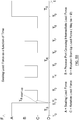
- a sealing load force A which can also be referred to as a process sealing load force, is applied by the biasing element 30, pushing the valve element, in this case the rotor 16, on the body 14, so that the valve element and the body interfaces 22, 24, or sealing surfaces, are sealed to one another.
- motor 32 compresses the biasing element 30, so that it applies the load force A on the rotor 16, which corresponds to the sealing load force.
- T S from T0 to T1
- the rotor is stationary, and fluid(s) can be circulated through channels and grooves of the stator 14 and rotor 16, respectively.
- the rotation start-up load can be applied for a very short period of time T R start-up , for example between 50 ms and 100 ms.
- the rotation start-up load (D) is determined depending on the type of process application for which the valve is used. For example, the rotation start-up load is determined depending on whether small leaks in the valve are acceptable or not. Of course, it can be considered to provide the rotor with process purging grooves, as disclosed in US 7,503,203 .
- the motor 1 slightly raises the plate supporting the biasing element 30 until load force C is detected by the strain gauge 38.
- the load force C corresponds to the rotation sealing load force.
- the load force is increased to the intermediate sealing load force B during three periods, each period corresponding to the rotor crossing over an intermediate port.
- Increasing the loading force to an intermediate loading force allows limiting the leaks and/or contamination risks when crossing over a port, since the sealing of the valve is increasing during this period.
- the intermediate loading force does not need to be as high as the sealing load force, and can be chosen to correspond to an acceptable leak rate, depending on the type of application in which the valve is used.
- the rotor is placed in the second operating position and the load force is increased to the sealing load force A.
- the sealing load force is increased by raising the plate supporting the resilient element so as to compress it.
- the motor 32 raises the movable member 17 until the strain gauge detects that load force A has been reached.
- the sealing load force can be first reduced to the rotation load force, prior rotating the rotor.
- operation of motor 26 and 32 is controlled based on readings from the position detector 28 and the load detector 38.
- the controller receives position and load force (or pressure) signals from their respective detectors and sends instruction signals to motors 26, 32 accordingly.
- the method described above includes as step of applying a sealing load force when the valve element is stationary and the valve is in operation, and of applying a reduced sealing load force, while moving the valve between the different positions.
- the sealing load force is applied at a process sealing load force when two or more ports are blocked or in communication, and the valve element is stationary. Slightly prior to, or upon moving the valve element, the sealing load force is reduced to a movement load force, so as to reduce friction and wear at the valve element and body interfaces.
- the sealing loading force applied on the valve element 16 is less, or smaller, when the valve element is moved between two positions, than when the valve is in operation and stationary.
- the loading force applied on the valve element is increased until the sealing load force is reached, in order to properly seal the valve element to the housing or stator, during operation of the valve.
- the movement load force ensures a minimal sealing between the valve element and the housing, corresponding to a tolerable leak rate, which may vary according to the application for which the valve is used.
- the sealing load force is generated irrespectively of the fluid pressure.
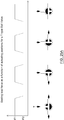
- the decrease of the sealing load force can occur rapidly, such as when using a motor as shown in the implementation of Figure 4 , and in graphs of Figure 5A and 5B , or it can be performed gradually as the rotor moves between the different positions, as is the case with the second to the fifth implementations explained later on.
- the loading force is reduced to a smaller loading force until it reaches a predetermined "movement loading force".
- the movement loading force can kept relatively constant or be varied until the next desired operating position is reached. The load force and pressure is thus released during movement of the valve elment, thereby reducing friction between the housing and the valve element, and the load force and pressure is re-applied when the valve element is in the next operating position, to ensure proper sealing.
- the loading force pressing the valve element 16 against the body 14 may be reduced well below the level that is normally required to seal the valve 10 at the operating process pressure. It may be reduced enough to maintain the sealing integrity, or reduced below the point where a tolerable leak occurs, in which case the purge groove can palliate for such leak.
- the valve is then quickly moved. The friction is therefore much lower, as is the wearing and the particle generation.
- the loading force pressing the valve element 16 against the body 14 can be increased well over the loading force generally used in standard valves, without risking of wearing the sealing surfaces or polymer extrusion through ports.
- softer materials include perfluoroelastomers , such as Kalrez® with a hardness/D shore value of 25, PFTE (Polytetrafluoroethylene, such as Teflon ®), with a D shore value of 65.
- PFTE Polytetrafluoroethylene, such as Teflon ®
- harder materials can also be used for the valve element of the present valve and method, such as PEEK (Polyether Ether Ketone) and VESPEL® with a D shore of 85 and PPS (Polyphenylene Sulfide) with a D shore of 90.
- the load applied on the rotor can be less, and sealing of the rotor against the stationary body is still sufficient.
- higher loads must be applied on the rotor to seal it properly against the stationary body.
- the load (and consequently the sealing load force) is reduced during rotation of the rotor, compared to when it is stationary (indicated as "sealing load").
- Material B being softer than material A, the sealing load applied on the rotor is less than for a rotor made of Material A.
- a cleaning intermediate force can be applied to allow a solvent or other appropriate cleaning/washing fluid to flow on all surface area without having to dismantle or disassemble the valve.
- This cleaning intermediate load is lower than the rotation load.
- that load can be low enough to allow the rotor to be slightly spaced from the stator.
- the method includes a step of compressing the biasing element to a first height when two ports of the housing are in fluid communication and the valve element is stationary in a first position; and a step of decompressing the biasing element up to a second height, thereby reducing the sealing load force applied on the valve element as the valve element moves towards a second position so as to interrupt flow of the fluid between said two ports.
- the method includes a step of recompressing the biasing element to the first height, when said two ports or other ports of the housing are in fluid communication and the rotor is stationary in the second position. It can also be considered to recompress the biasing element to the first height, when said two ports of the housing are blocked by the valve element and the rotor is stationary in the second position.
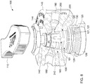
- the valve is a rotary valve 100 having a body 140 provided with a cavity 142 bordered by a sidewall 144 (identified in Figure 8 ).
- the sidewall 144 includes the body interface 220.
- the valve element is a rotor 160 disposed within the cavity 142.
- the rotor 160 has at least one channel 190, 191 opening on the interface 240 for interacting with the ports 200 of body interface 220.
- the rotor 160 is rotatable between different process positions, which are in this case angular positions, so as to permit or obstruct communication between the fluid passages 180 via the at least one channel 190.
- the actuating mechanism includes a rotatable shaft 126 connected to the rotor 160.
- the biasing element 130 is a compression spring assembly 130, and more particularly a stack of Belleville washers.
- the load varying mechanism 120 includes a static member 122, fixed in place thanks to a stopper 125, and the movable member 121.
- the movable member 121 comprises a portion 129 (identified in Figure 8 ) operatively linked to the rotor 160 so as to rotate along with the rotor, and a face 131 slidably in contact the face 132 of the static member 122 (the faces are identified in Figure 7 ).
- the faces 132, 131 of the static and movable members 122, 121 have respective profiles configured to move away or bring closer the static and movable members 122, 121 as the rotor rotates, thereby compressing or decompressing the biasing element 130.
- the static member and the movable member form an assembly having an overall height which can vary according to the position of the movable member 121. Since the members 121, 122 and the biasing element 30 are are contained within the body 140 of the valve, varying the height of the member assembly necessarily varies the height, and thus compressibility of the biasing element 130, which in turn affect the sealing load force applied by the biasing element on the rotor 160.
- the rotary valve illustrated in Figures 6 to 10 is a conical rotary valve 100.
- the body 140 is a housing having top and bottom ends.
- the rotor 160 has a frustro-conical body with a narrow end and a wide end.
- the rotor 160 fits within the cavity 142 with its narrow end disposed at the top end of the body 140.
- the at least one channel consisting in at least one groove 190 disposed at the surface of the frustro-conical body.
- the rotatable shaft 126 is connected to the narrow end of the frustro-conical body 160 and extends outwardly of the housing 140 top end.
- the load varying mechanism 120 is disposed at the wider end of the frustro-conical body; and the spring assembly 130 is disposed beneath the load varying mechanism120.
- the conical rotary valve 100 includes a disk 126 fixed at the bottom end of the housing, ensuring that the the spring assembly 130 is compressed with a minimal sealing load force. The disk 126 also closes off the cavity 142.
- the disposition of the load varying mechanism 120 and the biasing element 130 can be inverted, and the mechanism 120 and element 130 could be placed above the rotor 160 instead. Many possible configurations can be considered.
- the static and movable members of the load varying mechanism 120 are first and second cam washers 122, 121, their respective faces131, 132 including concave and convex portions 129, 123 (identified in Figures 9 and 10 ).
- first and second cam washers 122, 121 their respective faces131, 132 including concave and convex portions 129, 123 (identified in Figures 9 and 10 ).
- the respective convex portions 123 of the cam washers 121, 122 are in contact, thereby compressing the compression spring to a height Hs.
- the respective convex and concave portions 123, 127 are mated, thereby decompressing the spring assembly 130 to a height Hr, Hr being greater than Hs, thereby reducing the load force applied on the rotor 160.
- FIGS. 6 and 7 show the conical rotary valve 100.
- the valve 100 includes a stator 140.
- the stator 140 is provided with several channels, or fluid passages, 180, 181 through which process or purge fluids can be injected or drawn.
- a handle 110 allows moving the rotor housed in the stator 140 between different operating positions.
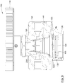
- the conical rotary valve 100 is provided with the stator 140 shown in cross-section.
- the valve includes ports 200 opening on the stator interface 220 and grooves 190, 191 provided on the rotor sealing interface 240.
- the grooves 190 allow placing selected process ports (one port 200 is identified on Figure 8 ) of the stator in fluid communication with one another, depending on the position of the rotor 160.
- Biasing elements 130 which are located below the rotor 160, allow pressing the rotor 160 against the stator 140 so as to seal the sealing surfaces of the rotor and stator when the valve is in operation.
- the biasing element 130 is a stack of Belleville washers.
- the rotary valve 100 also comprises load varying mechanism 120, which in the present case consists of two cam-washers 121, 122. The Belleville washers are compressed between the mechanism 120, and a disc 126, which is fixed within the stator 140.
- the rotary valve 100 is shown in a first operating position, two process ports of the stator being in fluid communication, port 200 and a common outlet port not shown.
- the cam washers 121, 122 are positioned such that their respective convex portions 123 are in contact, compressing the biasing element 130 such that its overall height corresponds to a height H S .
- the biasing element 130 applies a sealing loading force LFs on the rotor.
- the upper cam-washer moves along with the rotor 160, while the lower cam-washer will stay fixed, thanks to a stopper 125, which is best shown in Figure 7 .
- the respective surfaces of the cam-washers slide one on the other, gradually increasing the height H of the resilient element 130 until the configuration shown in Figure 9 is reached.
- the rotor 160 is now positioned so that the process ports of the stator 140 are no longer in fluid communication.
- the rotor is now located at mid-point between two operating positions. Convex and concave portions 123, 127 of the respective cam-washers are aligned and the cam washers are mated with one another.
- the overall height of the biasing element is increased to H R , H R being larger than H S .
- the static biasing element 130 is now slightly decompressed, which reduces the load force applied on the rotor 160.
- the resilient biasing element 130 is located between the cam washers 121, 122 and the fixed plate 126, which is preferably screwed to the stator 140.
- the lower section of the biasing element 130 rests on this fixed plate 126.
- rotating the handle, and thus of the upper cam washer 121 results in compressing or decompressing the biasing element 130, and thus in releasing or increasing the pressure applied on the rotor 160.
- the pressure is gradually reduced and then increased again until the second operating position it reached.
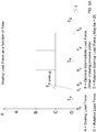
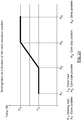
- FIG 11 is a graph presenting the loading force applied on the rotor in function of time.
- a sealing load force LF S is applied on the rotor, which corresponds to the valve position shown in Figure 9 , namely a first operating position.
- This sealing load force is applied during a period Ts, during which the valve is operated.
- T1 and T2 the rotor is rotated and the pressure applied on it is gradually reduced until it reaches a relatively constant rotation load force LF R .
- the period between T2 and T3 corresponds to the valve position shown in Figure 10 .
- the rotor is rotated up to the next operating position, namely the second operating position, which is reached at time T4.
- the actuating system has increased the loading force back to LFs.
- the actuation process can be repeated in the opposite direction.
- valves 12 to 25 three other implementations of the valve according to the invention are shown.
- the different variants of the valve are rotary valves, and more specifically they are ball-valves, 1000, 1000' and 1000".
- the valve 1000 has a handle 1110 for positioning the valve element, which is in this case a ball, in different positions.
- the ball-valve 1000 is a two-way valve, but of course other types of ball-valve can be considered for the valve of the present invention, such as three way L or T valves, shown in Figures 25A and 25B .
- the valve 1000 has fluid passages 1180 for circulating or blocking fluid with the valve 1000.
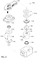
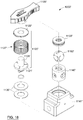
- FIG 13 is an exploded view of the valve of Figure 12 .
- the valve 1000 includes the handle 1110, a valve cap 1143, a load varying mechanism 1120, which comprises a movable member 1121 and a static member 1122.
- the biasing element consists in two Belleville washers 1130.
- a ball bearing mechanism 1133 is also provided.
- the valve element is in this case a ball valve 1160, which includes a through channel 1185.
- the ball is provided with purging grooves 1190, to circulate purging fluid therein.
- the body, or stator is a packing 1140 provided with a cavity 1121 for receiving the ball 1160.
- the packing 1140 has fluid passages opening as ports 1200 on the inner side of the packing 1140.
- the body (or packing) interface 1220 which is in contact with the valve element interface, corresponding in this case to the ball 1160 outer surface.
- a stack of biasing springs 1135 is provided below the packing 1140, to urge the packing 1140 in place within the valve enclosure, which includes a casing 1141 and a valve cap 1143.
- the spring constant of the biasing springs 1135 is of course smaller than the one of the resilient element 1130.
- the biasing springs 1135 are used to prevent the ball 1160 from adhering to the bottom of the packing 1140 when the sealing load force is reduced from the operational, sealing force to the rotational sealing load force.
- the rotor is the ball 1160 fitting within the cavity 1121, and the at least one channel is a through hole 1185 extending within the ball 1160.
- the valve enclosure has top and bottom sides and it houses the packing 1140 and the ball 1160.
- the rotatable shaft 1126 has its lower end connected to the ball and an upper end extending outside of the packing 1140 and the enclosure 1141,1143.
- the load varying mechanism 1120 and the spring assembly 1130 are is disposed above the packing, within the enclosure.
- a ball bearing 1133 is disposed between the packing 1140 and the compression spring assembly 1130.
- the load varying mechanism 1120 includes static and movable members which in this example are shaped as circular plates 1122, 1121 disposed radially within the enclosure 1141 when in use.
- the static and fixed members 1121 and 1122 are designed to cooperate when placed in the valve, each members having faces contacting one another, as best shown in Figure 15 and 16 .
- the circular plate 1121 of the movable member extends radially from the rotatable shaft 1126, but other configurations can be considered, as long as the movable member is operatively linked to the rotor, so as to move or rotate along the rotor's movement.
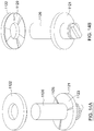
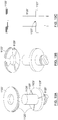
- the plate 1121 has a face with at least one portion with a sloped profile 1123.
- the sloped profile 1123 is very gentle, as can be seen in Figure 14D .
- the face of the static plate 1122 has one sliding block 1129 configured to slide along the sloped profile 1123.
- the circular plate 1121 includes at least two stoppers 1125 which delimits the portion with the sloped profile.
- the stoppers also limit movement of the sliding block between the stoppers, and consequently of the ball within the packing.
- the sloped profile could be provided on the fixed member 1122, and the sliding block on the movable member 1121.
- the plate 1121 comprises three portions with sloped profile.
- the plates 1121 and 1121 are coupled to one another and disposed above the biasing element 1130.
- the biasing element and the plates 1121, 1122 are contained within the valve cap 1143 and the ball bearing 1133.
- the total height H TOT is thus fixed and cannot be varied.
- the overall height of the load varying mechanism is H VL1 and the biasing element 1130 as a height H B1 .
- the portion of the annular plate 1121 with the sloped profile includes two flat portions 1124 disposed on each side of the sloped profile 1123, between the two stoppers 1125.
- the profile of the load force applied by the biasing element 130 corresponds to the slope of the surface of the annular plate 1121.
- FIG. 17 to 19 another implementation of a ball-valve is shown.
- the vavle 1000' is similar to the one of Figures 12 to 16 , excepted that the geometry of parts is slightly changed.
- the packing 1140' is made of 2 parts, and the fixed annular plate 1122' is screwed to the valve enclosure 1141'.
- Compressible annular seals 1127' surround the load varying mechanism 1120'.
- the load biasing mechanism is similar to the one of the valve 1000, of Figures 12 to 16 .
- the mechanism 1120' includes a static member 1122' and a movable member 1121'.
- the movable member 1121' includes portions with sloped profiles delimited by stoppers 1125'.
- the static member 1122' includes sliding blocks 1129' which can slide over the sloped profile 1123'. Rotation of the shaft 1126' raises or lowers the plate 1121' relative to the static plate 1122', thereby varying the height of the biasing element 1130', which in turn varies the load applied by the biasing element on the valve element 1160'.
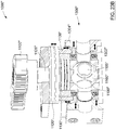
- valve 1000 mainly differs from the other two valves 1000 and 1000' because it includes a second mechanism which seals the packing and ball interfaces in a direction orthogonal to the sealing load force applied by the biasing element 1130".
- the baising or spring assembly 1130" can thus be referred to as a first spring assembly which biases the ball 1160" axially, or vertically, toward the packing 1140".
- the valve 1000 includes a second spring assembly 1137" which biases the packing 1140" towards the ball 1160" in a radial, or lateral, direction.
- the valve 1000 also includes a load transfer mechanism 1300" operatively linked to the movable member 1121" of the load varying mechanism 1120", for varying the load force applied on the second biasing assembly 1137" proportionally to the load force applied by the first spring assembly 1130".
- the second spring assembly 1137" is disposed outside of the packing and surrounds the fluid passages.
- the load transfer mechanism 1300" includes a fixed plate 1304" and a slidable plate 1302" disposed axially, or vertically, relative to the enclosure.
- the plate 1032" is operatively connected, and in this case in direct contact, with the second spring assembly 1137".
- the plates 1302" and 1304" have mating inclined surfaces.
- the transfer mechanism 1300” also includes a rod 1139" disposed between the movable member 1121" of the load varying mechanism 1120" and the slidable plate 1302" of the load transfer mechanism 1300".
- the movable member 1121' Upon rotation of the shaft 1126", such as shown in Figure 23B , the movable member 1121' is lowered for compressing the first spring assembly 1130".
- the rod 1139" is forced downwardly, pushing the slidable plate 1302".
- the plate 1302" can move thanks to springs located on each side of the plate 1302'. Because of its slanted or inclined profile, the plate 1302" moves downwarly and laterally, towards the ball 1160", when the baising assembly 1130" is compressed.
- the plate 1032" compresses the second spring assembly 1137" radially, further increasing sealing of the packing and the ball.
- An advantage of the method and valves above is that they require less torque to be operated, especially for the implementation presented in Figure 4 .
- Another advantage is that the pressure applied on the valve element does not depend upon the pressure required for the application process.
- the pressure applied on the valve element of the valve by the biasing element and load varying mechanism is completely independent from the pressure used in the analytical system, or of the force of the motor used to rotate the rotor.
- the process fluid to apply the loading force on the rotor; however, in this case the pressure of the fluid used for applying on the rotor is controlled independently from the pressure used in the analytical process.
- the method described in the present application is applicable to different types of valve, including conical valve, ball valves and sliding valves.
- the method, actuating system and rotary valve described herein allow lowering the loading force applied on the rotor during its rotation, so as to reduce friction between the rotor and stator sealing surfaces. Reducing said friction diminishes in turn wear of the sealing surfaces, increasing the lifetime of the valve.
Landscapes
- Engineering & Computer Science (AREA)
- General Engineering & Computer Science (AREA)
- Mechanical Engineering (AREA)
- Physics & Mathematics (AREA)
- Health & Medical Sciences (AREA)
- Life Sciences & Earth Sciences (AREA)
- Chemical & Material Sciences (AREA)
- Analytical Chemistry (AREA)
- Biochemistry (AREA)
- General Health & Medical Sciences (AREA)
- General Physics & Mathematics (AREA)
- Immunology (AREA)
- Pathology (AREA)
- Multiple-Way Valves (AREA)
- Electrically Driven Valve-Operating Means (AREA)
- Mechanically-Actuated Valves (AREA)
- Details Of Valves (AREA)
Claims (13)
- Verfahren zur Kanalisierung eines Fluids durch verschiedene Durchgänge eines Ventils (10, 100, 1000), wobei das Verfahren die folgenden Schritte umfasst:a) Bereitstellen des Ventils (10, 100, 1000), umfassend:- ein Gehäuse (14, 140, 1140), ausgestattet mit den Fluiddurchgängen (18, 180, 1180), zum Zirkulieren des Fluids darin bei einem Fluiddruck, wobei das Gehäuse eine Gehäuseschnittstelle (22, 220, 1220) mit Anschlüssen (20, 200, 1200) aufweist, die mit den Fluiddurchgängen (18, 180, 1180) verbunden sind;- ein Ventilelement (16, 160, 1160), aufweisend eine Ventilelementschnittstelle (24, 240, 1240), die der Gehäuseschnittstelle gegenüber liegt, wobei das Ventilelement (16, 160, 1160) mit den Anschlüssen der Gehäuseschnittstelle (20, 200, 1200) interagiert, wobei das Ventilelement zwischen verschiedenen Positionen beweglich ist, um die Kommunikation zwischen den Fluddurchgängen zu ermöglichen oder zu blockieren; und- ein Vorspannungselement (30, 130, 1130) zum Vorspannen der Ventilelementschnittstelle gegen die Gehäuseschnittstelle;b) Anwenden der Dichtlastkraft mit Hilfe des Vorspannungselements (30, 130, 1130), wenn das Ventilelement stationär ist und das Ventil in Betrieb ist; undc) Anwenden einer reduzierten Dichtlastkraft mit Hilfe des Vorspannungselements (30, 130, 1130) während der Bewegung des Ventils zwischen den verschiedenen Positionen, dadurch gekennzeichnet, dass:
Schritt c) einen Unterschritt des Anwendens einer Dichtlastkraft mit einem Zwischen-Dichtlastkraftwert umfasst, wenn sich das Ventilelement (16, 160, 1160) an den Anschlüssen (20, 200, 1200) des Gehäuses vorbeibewegt, wobei die Zwischen-Dichtlastkraft einen Wert zwischen einem Prozessdichtkraftwert, der der Dichtlastkraft, angewendet in Schritt b) entspricht, und einen Bewegungsdichtkraftwert aufweist, der zwischen zwei aufeinander folgenden der Anschlüsse angewendet wird. - Verfahren nach Anspruch 1, wobei die Dichtlastkraft unabhängig vom Fluiddruck generiert wird.
- Verfahren nach Anspruch 1 oder 2, wobei in Schritt a) das Ventil ein Drehventil (10, 100, 1000) ist, wobei das Ventilelement ein Rotor ist; und in Schritt c) die Bewegung des Ventilelements aus der Drehung des Rotors besteht.
- Verfahren nach Anspruch 1, 2 oder 3, wobei Schritt c) durchgeführt wird, indem die Dichtlastkraft allmählich reduziert wird, wenn sich der Rotor (16, 160, 1160) zwischen zwei verschiedenen Positionen bewegt.
- Verfahren nach einem der Ansprüche 1 bis 4, umfassend einen Schritt des Reduzierens der Dichtlastkraft auf einen Anfangswert vor dem oder beim Beginn des Bewegens des Ventilelements (16, 160, 1160).
- Verfahren nach einem der Ansprüche 1 bis 5, wobei in Schritt c) die Dichtlastkraft durch Variieren einer Größe des Vorspannungselements (30, 130, 1130) reduziert wird.
- Verfahren nach Anspruch 6, wobei die Größe des Vorspannungselements (13, 130, 1130) einer bestimmten Höhe entspricht, wobei die Höhe des Vorspannungselements unter Verwendung eines steuerbaren Motors variiert wird.
- Verfahren nach Anspruch 6, wobei die Höhe des Vorspannungselements (13, 130, 1130) unter Verwendung einer mechanischen Anordnung, die mit dem Vorspannungselement in Betrieb verbunden ist, variiert wird.
- Verfahren nach einem der Ansprüche 1 bis 7, umfassend einen Schritt des Messens einer Betriebstemperatur des Ventils und des Bestimmens der Dichtlastkraft, die in Schritt b) und c) angewendet werden soll, basierend auf der gemessenen Betriebstemperatur.
- Verfahren nach einem der Ansprüche 1 bis 9, wobei- Schritt b) durch Komprimieren des Vorspannungselements (30, 130, 1130) auf eine erste Höhe durchgeführt wird, wenn zwei Anschlüsse des Gehäuses in fluidischer Kommunikation sind und das Ventilelement stationär in einer ersten Position ist; und- Schritt c) durch Dekomprimieren des Vorspannungselements (30, 130, 1130) bis zu einer zweiten Höhe durchgeführt wird, wodurch die Dichtlastkraft reduziert wird, die auf das Ventilelement angewendet wird, wenn sich das Ventilelement in eine zweite Position bewegt, um den Fluidstrom zwischen den zwei Anschlüssen zu unterbrechen.
- Verfahren nach Anspruch 10, umfassend einen Schritt d) des erneuten Komprimierens des Vorspannungselements (30, 130, 1130) auf die erste Höhe, wenn die zwei Anschlüsse oder anderen Anschlüsse des Gehäuses in fluidischer Kommunikation sind und der Rotor stationär in der zweiten Position ist.
- Verfahren nach Anspruch 10, umfassend einen Schritt d) des erneuten Komprimierens des Vorspannungselements (30, 130, 1130) auf die erste Höhe, wenn die zwei Anschlüsse des Gehäuses durch das Ventilelement blockiert sind und der Rotor stationär in der zweiten Position ist.
- Verfahren nach Anspruch 1, wobei das Verfahren in einem Probestrom-Auswahlventil durchgeführt wird, wenn es einen Anschluss quert.
Applications Claiming Priority (2)
| Application Number | Priority Date | Filing Date | Title |
|---|---|---|---|
| US201261679971P | 2012-08-06 | 2012-08-06 | |
| PCT/CA2013/050594 WO2014022932A1 (en) | 2012-08-06 | 2013-07-31 | Valve with a load varying mechanism, and method of operating the same |
Publications (4)
| Publication Number | Publication Date |
|---|---|
| EP2880342A1 EP2880342A1 (de) | 2015-06-10 |
| EP2880342A4 EP2880342A4 (de) | 2015-08-26 |
| EP2880342B1 true EP2880342B1 (de) | 2018-09-05 |
| EP2880342B8 EP2880342B8 (de) | 2018-10-31 |
Family
ID=50067335
Family Applications (1)
| Application Number | Title | Priority Date | Filing Date |
|---|---|---|---|
| EP13828457.5A Not-in-force EP2880342B8 (de) | 2012-08-06 | 2013-07-31 | Ventil mit einem lastvariierenden mechanismus und betriebsverfahren dafür |
Country Status (5)
| Country | Link |
|---|---|
| US (2) | US9435440B2 (de) |
| EP (1) | EP2880342B8 (de) |
| JP (1) | JP6129967B2 (de) |
| CN (1) | CN104662347B (de) |
| WO (1) | WO2014022932A1 (de) |
Families Citing this family (25)
| Publication number | Priority date | Publication date | Assignee | Title |
|---|---|---|---|---|
| US9801767B2 (en) * | 2013-03-14 | 2017-10-31 | Kap Medical, Inc. | Patient support apparatus and method |
| CN104874926A (zh) * | 2015-06-04 | 2015-09-02 | 肖叶 | 一种半导体激光打标机自动开闭进气口 |
| CN106931183B (zh) * | 2015-12-31 | 2019-02-01 | 世界先进积体电路股份有限公司 | 节流阀 |
| US10018281B2 (en) * | 2016-06-16 | 2018-07-10 | Vanguard International Semiconductor Corporation | Throttle valve |
| CN106704639A (zh) * | 2016-12-02 | 2017-05-24 | 深圳市恒永达科技有限公司 | 一种平面密封的流道选择阀 |
| US11054054B2 (en) | 2016-12-09 | 2021-07-06 | Idex Health & Science Llc | High pressure valve with multi-piece stator assembly |
| US10384151B2 (en) * | 2016-12-09 | 2019-08-20 | Idex Health & Science Llc | High pressure valve with two-piece stator assembly |
| JP7584220B2 (ja) * | 2017-05-08 | 2024-11-15 | アイデックス ヘルス アンド サイエンス エルエルシー | ローカライズされた不揮発性メモリを有する流れ制御組立体 |
| WO2019043908A1 (ja) * | 2017-09-01 | 2019-03-07 | 株式会社島津製作所 | 切替バルブ |
| WO2019140532A1 (en) | 2018-01-19 | 2019-07-25 | Spartan Bioscience Inc. | Fluid handling apparatus |
| WO2019144228A1 (en) | 2018-01-23 | 2019-08-01 | Ldetek Inc. | Valve assembly for a gas chromatograph |
| US11175265B2 (en) * | 2019-03-04 | 2021-11-16 | Valeo Instruments Company, L.P. | Valve for high and ultra-high pressure liquid chromatography |
| GB2591794A (en) | 2020-02-07 | 2021-08-11 | Imperial College Innovations Ltd | Valve |
| CN116057375B (zh) | 2020-07-30 | 2026-03-20 | 安捷伦科技有限公司 | 具有轴向角补偿件的阀 |
| CN116635716A (zh) * | 2020-10-28 | 2023-08-22 | 沃特世科技公司 | 带有具有附加输入和/或输出的整体式阀/三通的用于液相色谱柱的端部配件 |
| US12553867B2 (en) | 2020-12-15 | 2026-02-17 | Mecanique Analytique Inc. | Variable load chromatography valve for fluid analysis |
| US12320441B1 (en) * | 2021-02-08 | 2025-06-03 | Schivo Medical Limited | Centering electronic rotary valve |
| US12297931B2 (en) | 2021-02-08 | 2025-05-13 | Schivo Medical Limited | Centering electronic rotary valve |
| GB2609634A (en) * | 2021-08-10 | 2023-02-15 | Imperial College Innovations Ltd | Valve |
| DE102021128649A1 (de) * | 2021-11-03 | 2023-05-04 | Agilent Technologies, Inc. | Rotationsventil mit Ausgleichselement zum Ausgleich eines axialen Versatzes |
| CN116697095A (zh) * | 2023-05-22 | 2023-09-05 | 浙江智汇汽车热管理科技有限公司 | 电动阀 |
| FR3152849A1 (fr) * | 2023-09-07 | 2025-03-14 | Khaled Abousaleh | Dispositif vanne rotative de précision |
| DE102024203159A1 (de) | 2024-04-08 | 2025-10-09 | Schaeffler Technologies AG & Co. KG | Kraftübertragungs- und Anhebemittel für eine Drehventilanordnung, Drehventilanordnung, Pumpen-Ventil-Einheit, Thermomanagementsystem und Elektrofahrzeug |
| WO2025245454A1 (en) * | 2024-05-23 | 2025-11-27 | Schivo Medical Limited | Rotary valve |
| CN120701802B (zh) * | 2025-08-22 | 2025-11-14 | 深圳市恒永达科技股份有限公司 | 一种防吸合卡死的旋切阀及控制方法 |
Family Cites Families (32)
| Publication number | Priority date | Publication date | Assignee | Title |
|---|---|---|---|---|
| US1466828A (en) * | 1921-05-02 | 1923-09-04 | George C Hanley | Shut-off cock |
| US2449733A (en) * | 1944-04-22 | 1948-09-21 | United Aircraft Prod | Valve actuating mechanism |
| US2541715A (en) * | 1945-02-15 | 1951-02-13 | Gertrude E Oestreicher | Stop valve |
| US2615672A (en) * | 1948-11-19 | 1952-10-28 | Tri Clover Machine Co | Seal for axially movable rotary plug valves |
| US3297053A (en) | 1963-12-30 | 1967-01-10 | Carle Instr Inc | Selector valve |
| US3640310A (en) | 1969-06-26 | 1972-02-08 | Hayward Mfg Co Inc | Multiport valve |
| US4156437A (en) * | 1978-02-21 | 1979-05-29 | The Perkin-Elmer Corporation | Computer controllable multi-port valve |
| US4310022A (en) * | 1980-05-07 | 1982-01-12 | Givat Chaim-Ichud | Fluid distributor system |
| US4501297A (en) * | 1982-04-08 | 1985-02-26 | Automatic Switch Company | Rotary valve |
| US4550742A (en) | 1984-01-23 | 1985-11-05 | Stearns Stanley D | Variable tensioning system for shear seal valves |
| US4867414A (en) | 1989-01-10 | 1989-09-19 | Velan Inc. | Ball valve |
| JPH0429382A (ja) | 1990-05-24 | 1992-01-31 | Hitachi Ltd | ガスレ―ザ装置とレ―ザ加工システム |
| JP2564156Y2 (ja) * | 1992-05-06 | 1998-03-04 | 横河電機株式会社 | 回転式マイクロバルブ |
| US6643946B1 (en) | 1994-02-02 | 2003-11-11 | David N. Schuh | Bearing clearance detector |
| JPH07260022A (ja) * | 1994-03-23 | 1995-10-13 | Saginomiya Seisakusho Inc | ディスク回転式電動多方弁 |
| JP3465095B2 (ja) * | 1995-03-15 | 2003-11-10 | 太平洋精工株式会社 | 空気調和機用四方弁 |
| US6098646A (en) * | 1997-02-19 | 2000-08-08 | Ecolab Inc. | Dispensing system with multi-port valve for distributing use dilution to a plurality of utilization points and position sensor for use thereon |
| US6193213B1 (en) | 1999-03-05 | 2001-02-27 | Valco Instruments Company, Inc. | Variable pressure loading system utilizing combined spring and fluid pressure |
| US6378841B1 (en) | 1999-10-29 | 2002-04-30 | Larry R. Russell | Quarter-turn rotary plug valve with seats reciprocable during operation |
| US6453946B2 (en) | 2000-03-10 | 2002-09-24 | Rheodyne, Lp | Long lifetime fluid switching valve |
| CN1329682C (zh) | 2002-01-18 | 2007-08-01 | 斯瓦戈洛克公司 | 具有整体式填密件的球阀 |
| ATE529671T1 (de) | 2004-08-25 | 2011-11-15 | Mecanique Analytique Inc | Drehschieber und diesen verwendendes analytisches chromatographisches system |
| DE102004063270B4 (de) * | 2004-12-23 | 2007-01-04 | Cera System Verschleissschutz Gmbh | Kugelhahn und ein Verfahren zu dessen Betrieb |
| US7377291B2 (en) * | 2005-12-28 | 2008-05-27 | Serveron Corporation | Multiport rotary valve |
| US7819948B2 (en) * | 2007-10-29 | 2010-10-26 | Air Products And Chemicals, Inc. | Rotary valve |
| WO2009078450A1 (ja) * | 2007-12-17 | 2009-06-25 | Shimadzu Corporation | 流路切換えバルブ |
| EP2331859B1 (de) | 2008-09-09 | 2018-10-17 | Air Products and Chemicals, Inc. | Druckentlastetes kompaktdrehventil |
| WO2010045198A1 (en) | 2008-10-13 | 2010-04-22 | Swangelok Company | Valve sealing arrangements and methods |
| US8876081B2 (en) * | 2009-07-13 | 2014-11-04 | Idex Health & Science Llc | Rotary shear valve assembly with a polymer insert device |
| WO2011038511A1 (en) * | 2009-09-30 | 2011-04-07 | Mecanique Analytique Inc. | Conical rotary valve for chromatographic applications |
| EP2341269A1 (de) | 2009-12-22 | 2011-07-06 | Valbart S.r.l. | Auf einem Drehzapfen montiertes Kugelventil mit Umkehr-Kolben-Effekt |
| CN103518092B (zh) * | 2011-05-05 | 2015-11-25 | 沃特世科技公司 | 具有可变压力加载的高压流体切换阀 |
-
2013
- 2013-07-31 US US14/420,180 patent/US9435440B2/en active Active
- 2013-07-31 EP EP13828457.5A patent/EP2880342B8/de not_active Not-in-force
- 2013-07-31 CN CN201380050465.1A patent/CN104662347B/zh not_active Expired - Fee Related
- 2013-07-31 JP JP2015525699A patent/JP6129967B2/ja active Active
- 2013-07-31 WO PCT/CA2013/050594 patent/WO2014022932A1/en not_active Ceased
-
2016
- 2016-08-08 US US15/231,149 patent/US10428960B2/en active Active
Non-Patent Citations (1)
| Title |
|---|
| None * |
Also Published As
| Publication number | Publication date |
|---|---|
| JP2015528544A (ja) | 2015-09-28 |
| EP2880342B8 (de) | 2018-10-31 |
| WO2014022932A1 (en) | 2014-02-13 |
| EP2880342A4 (de) | 2015-08-26 |
| US20160348795A1 (en) | 2016-12-01 |
| CN104662347B (zh) | 2017-10-20 |
| CN104662347A (zh) | 2015-05-27 |
| US9435440B2 (en) | 2016-09-06 |
| JP6129967B2 (ja) | 2017-05-17 |
| US10428960B2 (en) | 2019-10-01 |
| EP2880342A1 (de) | 2015-06-10 |
| US20150198255A1 (en) | 2015-07-16 |
Similar Documents
| Publication | Publication Date | Title |
|---|---|---|
| US10428960B2 (en) | Valve with a load varying mechanism, and method of operating the same | |
| US9488277B2 (en) | Seal assemblies for reciprocating and rotary applications | |
| KR102197312B1 (ko) | 볼 밸브 | |
| US4451047A (en) | Seal | |
| CN101849126B (zh) | 通道转换阀 | |
| US8104506B2 (en) | Diaphragm-sealed valve having intermediate communication ports | |
| TW565668B (en) | Ball valve | |
| US20140210166A1 (en) | Cartridge seal assemblies and associated methods | |
| KR20070032821A (ko) | 볼 밸브 시트 구조 | |
| CA2735807C (en) | Temperature compensated valve for gas chromatography | |
| US10914394B2 (en) | Fluidic valve with contactless force transmission for pressing together stator and rotor | |
| GB2103310A (en) | Seal | |
| US10578229B2 (en) | Flexible stem bellow assembly | |
| US7219898B2 (en) | Spring supported dual element face seal with a run surface sleeve | |
| US8851452B2 (en) | Self-aligned plunger for chromatographic valve | |
| CN111750170B (zh) | 用于排出能够流动的介质的装置以及用于运行这种装置的方法 | |
| CN109882597A (zh) | 具有轴封的衬套 | |
| CA2462091C (en) | Stem or shaft seal arrangement | |
| KR20030086952A (ko) | 볼 밸브 | |
| US12553867B2 (en) | Variable load chromatography valve for fluid analysis | |
| KR20240099609A (ko) | 볼밸브 실링구조 | |
| RU2162181C1 (ru) | Вентильная головка сантехнической арматуры | |
| WO2021195338A1 (en) | Metering pump for liquid chromatography |
Legal Events
| Date | Code | Title | Description |
|---|---|---|---|
| PUAI | Public reference made under article 153(3) epc to a published international application that has entered the european phase |
Free format text: ORIGINAL CODE: 0009012 |
|
| 17P | Request for examination filed |
Effective date: 20150303 |
|
| AK | Designated contracting states |
Kind code of ref document: A1 Designated state(s): AL AT BE BG CH CY CZ DE DK EE ES FI FR GB GR HR HU IE IS IT LI LT LU LV MC MK MT NL NO PL PT RO RS SE SI SK SM TR |
|
| AX | Request for extension of the european patent |
Extension state: BA ME |
|
| RA4 | Supplementary search report drawn up and despatched (corrected) |
Effective date: 20150724 |
|
| RIC1 | Information provided on ipc code assigned before grant |
Ipc: F16K 3/16 20060101AFI20150720BHEP Ipc: F16K 11/08 20060101ALI20150720BHEP Ipc: F16K 3/14 20060101ALI20150720BHEP Ipc: F16K 5/14 20060101ALI20150720BHEP Ipc: F16K 11/074 20060101ALI20150720BHEP Ipc: F16K 11/072 20060101ALI20150720BHEP Ipc: F16K 3/10 20060101ALI20150720BHEP Ipc: F16K 5/20 20060101ALI20150720BHEP |
|
| DAX | Request for extension of the european patent (deleted) | ||
| STAA | Information on the status of an ep patent application or granted ep patent |
Free format text: STATUS: EXAMINATION IS IN PROGRESS |
|
| 17Q | First examination report despatched |
Effective date: 20170302 |
|
| GRAP | Despatch of communication of intention to grant a patent |
Free format text: ORIGINAL CODE: EPIDOSNIGR1 |
|
| STAA | Information on the status of an ep patent application or granted ep patent |
Free format text: STATUS: GRANT OF PATENT IS INTENDED |
|
| INTG | Intention to grant announced |
Effective date: 20180216 |
|
| GRAS | Grant fee paid |
Free format text: ORIGINAL CODE: EPIDOSNIGR3 |
|
| GRAA | (expected) grant |
Free format text: ORIGINAL CODE: 0009210 |
|
| STAA | Information on the status of an ep patent application or granted ep patent |
Free format text: STATUS: THE PATENT HAS BEEN GRANTED |
|
| AK | Designated contracting states |
Kind code of ref document: B1 Designated state(s): AL AT BE BG CH CY CZ DE DK EE ES FI FR GB GR HR HU IE IS IT LI LT LU LV MC MK MT NL NO PL PT RO RS SE SI SK SM TR |
|
| REG | Reference to a national code |
Ref country code: GB Ref legal event code: FG4D |
|
| REG | Reference to a national code |
Ref country code: CH Ref legal event code: EP |
|
| REG | Reference to a national code |
Ref country code: AT Ref legal event code: REF Ref document number: 1038200 Country of ref document: AT Kind code of ref document: T Effective date: 20180915 |
|
| REG | Reference to a national code |
Ref country code: IE Ref legal event code: FG4D |
|
| REG | Reference to a national code |
Ref country code: DE Ref legal event code: R096 Ref document number: 602013043306 Country of ref document: DE |
|
| RAP2 | Party data changed (patent owner data changed or rights of a patent transferred) |
Owner name: APN-AFP INC. |
|
| REG | Reference to a national code |
Ref country code: CH Ref legal event code: PK Free format text: BERICHTIGUNG B8 |
|
| REG | Reference to a national code |
Ref country code: CH Ref legal event code: NV Representative=s name: ANDRE ROLAND S.A., CH |
|
| REG | Reference to a national code |
Ref country code: NL Ref legal event code: FP |
|
| REG | Reference to a national code |
Ref country code: LT Ref legal event code: MG4D |
|
| PG25 | Lapsed in a contracting state [announced via postgrant information from national office to epo] |
Ref country code: GR Free format text: LAPSE BECAUSE OF FAILURE TO SUBMIT A TRANSLATION OF THE DESCRIPTION OR TO PAY THE FEE WITHIN THE PRESCRIBED TIME-LIMIT Effective date: 20181206 Ref country code: BG Free format text: LAPSE BECAUSE OF FAILURE TO SUBMIT A TRANSLATION OF THE DESCRIPTION OR TO PAY THE FEE WITHIN THE PRESCRIBED TIME-LIMIT Effective date: 20181205 Ref country code: NO Free format text: LAPSE BECAUSE OF FAILURE TO SUBMIT A TRANSLATION OF THE DESCRIPTION OR TO PAY THE FEE WITHIN THE PRESCRIBED TIME-LIMIT Effective date: 20181205 Ref country code: SE Free format text: LAPSE BECAUSE OF FAILURE TO SUBMIT A TRANSLATION OF THE DESCRIPTION OR TO PAY THE FEE WITHIN THE PRESCRIBED TIME-LIMIT Effective date: 20180905 Ref country code: LT Free format text: LAPSE BECAUSE OF FAILURE TO SUBMIT A TRANSLATION OF THE DESCRIPTION OR TO PAY THE FEE WITHIN THE PRESCRIBED TIME-LIMIT Effective date: 20180905 Ref country code: RS Free format text: LAPSE BECAUSE OF FAILURE TO SUBMIT A TRANSLATION OF THE DESCRIPTION OR TO PAY THE FEE WITHIN THE PRESCRIBED TIME-LIMIT Effective date: 20180905 Ref country code: FI Free format text: LAPSE BECAUSE OF FAILURE TO SUBMIT A TRANSLATION OF THE DESCRIPTION OR TO PAY THE FEE WITHIN THE PRESCRIBED TIME-LIMIT Effective date: 20180905 |
|
| REG | Reference to a national code |
Ref country code: AT Ref legal event code: MK05 Ref document number: 1038200 Country of ref document: AT Kind code of ref document: T Effective date: 20180905 |
|
| PG25 | Lapsed in a contracting state [announced via postgrant information from national office to epo] |
Ref country code: HR Free format text: LAPSE BECAUSE OF FAILURE TO SUBMIT A TRANSLATION OF THE DESCRIPTION OR TO PAY THE FEE WITHIN THE PRESCRIBED TIME-LIMIT Effective date: 20180905 Ref country code: AL Free format text: LAPSE BECAUSE OF FAILURE TO SUBMIT A TRANSLATION OF THE DESCRIPTION OR TO PAY THE FEE WITHIN THE PRESCRIBED TIME-LIMIT Effective date: 20180905 Ref country code: LV Free format text: LAPSE BECAUSE OF FAILURE TO SUBMIT A TRANSLATION OF THE DESCRIPTION OR TO PAY THE FEE WITHIN THE PRESCRIBED TIME-LIMIT Effective date: 20180905 |
|
| PG25 | Lapsed in a contracting state [announced via postgrant information from national office to epo] |
Ref country code: EE Free format text: LAPSE BECAUSE OF FAILURE TO SUBMIT A TRANSLATION OF THE DESCRIPTION OR TO PAY THE FEE WITHIN THE PRESCRIBED TIME-LIMIT Effective date: 20180905 Ref country code: IT Free format text: LAPSE BECAUSE OF FAILURE TO SUBMIT A TRANSLATION OF THE DESCRIPTION OR TO PAY THE FEE WITHIN THE PRESCRIBED TIME-LIMIT Effective date: 20180905 Ref country code: AT Free format text: LAPSE BECAUSE OF FAILURE TO SUBMIT A TRANSLATION OF THE DESCRIPTION OR TO PAY THE FEE WITHIN THE PRESCRIBED TIME-LIMIT Effective date: 20180905 Ref country code: ES Free format text: LAPSE BECAUSE OF FAILURE TO SUBMIT A TRANSLATION OF THE DESCRIPTION OR TO PAY THE FEE WITHIN THE PRESCRIBED TIME-LIMIT Effective date: 20180905 Ref country code: IS Free format text: LAPSE BECAUSE OF FAILURE TO SUBMIT A TRANSLATION OF THE DESCRIPTION OR TO PAY THE FEE WITHIN THE PRESCRIBED TIME-LIMIT Effective date: 20190105 Ref country code: CZ Free format text: LAPSE BECAUSE OF FAILURE TO SUBMIT A TRANSLATION OF THE DESCRIPTION OR TO PAY THE FEE WITHIN THE PRESCRIBED TIME-LIMIT Effective date: 20180905 Ref country code: RO Free format text: LAPSE BECAUSE OF FAILURE TO SUBMIT A TRANSLATION OF THE DESCRIPTION OR TO PAY THE FEE WITHIN THE PRESCRIBED TIME-LIMIT Effective date: 20180905 Ref country code: PL Free format text: LAPSE BECAUSE OF FAILURE TO SUBMIT A TRANSLATION OF THE DESCRIPTION OR TO PAY THE FEE WITHIN THE PRESCRIBED TIME-LIMIT Effective date: 20180905 |
|
| PG25 | Lapsed in a contracting state [announced via postgrant information from national office to epo] |
Ref country code: SK Free format text: LAPSE BECAUSE OF FAILURE TO SUBMIT A TRANSLATION OF THE DESCRIPTION OR TO PAY THE FEE WITHIN THE PRESCRIBED TIME-LIMIT Effective date: 20180905 Ref country code: PT Free format text: LAPSE BECAUSE OF FAILURE TO SUBMIT A TRANSLATION OF THE DESCRIPTION OR TO PAY THE FEE WITHIN THE PRESCRIBED TIME-LIMIT Effective date: 20190105 Ref country code: SM Free format text: LAPSE BECAUSE OF FAILURE TO SUBMIT A TRANSLATION OF THE DESCRIPTION OR TO PAY THE FEE WITHIN THE PRESCRIBED TIME-LIMIT Effective date: 20180905 |
|
| REG | Reference to a national code |
Ref country code: DE Ref legal event code: R097 Ref document number: 602013043306 Country of ref document: DE |
|
| PLBE | No opposition filed within time limit |
Free format text: ORIGINAL CODE: 0009261 |
|
| STAA | Information on the status of an ep patent application or granted ep patent |
Free format text: STATUS: NO OPPOSITION FILED WITHIN TIME LIMIT |
|
| PG25 | Lapsed in a contracting state [announced via postgrant information from national office to epo] |
Ref country code: DK Free format text: LAPSE BECAUSE OF FAILURE TO SUBMIT A TRANSLATION OF THE DESCRIPTION OR TO PAY THE FEE WITHIN THE PRESCRIBED TIME-LIMIT Effective date: 20180905 |
|
| 26N | No opposition filed |
Effective date: 20190606 |
|
| PG25 | Lapsed in a contracting state [announced via postgrant information from national office to epo] |
Ref country code: SI Free format text: LAPSE BECAUSE OF FAILURE TO SUBMIT A TRANSLATION OF THE DESCRIPTION OR TO PAY THE FEE WITHIN THE PRESCRIBED TIME-LIMIT Effective date: 20180905 |
|
| PG25 | Lapsed in a contracting state [announced via postgrant information from national office to epo] |
Ref country code: MC Free format text: LAPSE BECAUSE OF FAILURE TO SUBMIT A TRANSLATION OF THE DESCRIPTION OR TO PAY THE FEE WITHIN THE PRESCRIBED TIME-LIMIT Effective date: 20180905 |
|
| PG25 | Lapsed in a contracting state [announced via postgrant information from national office to epo] |
Ref country code: TR Free format text: LAPSE BECAUSE OF FAILURE TO SUBMIT A TRANSLATION OF THE DESCRIPTION OR TO PAY THE FEE WITHIN THE PRESCRIBED TIME-LIMIT Effective date: 20180905 |
|
| REG | Reference to a national code |
Ref country code: BE Ref legal event code: MM Effective date: 20190731 |
|
| PG25 | Lapsed in a contracting state [announced via postgrant information from national office to epo] |
Ref country code: BE Free format text: LAPSE BECAUSE OF NON-PAYMENT OF DUE FEES Effective date: 20190731 Ref country code: LU Free format text: LAPSE BECAUSE OF NON-PAYMENT OF DUE FEES Effective date: 20190731 |
|
| PG25 | Lapsed in a contracting state [announced via postgrant information from national office to epo] |
Ref country code: FR Free format text: LAPSE BECAUSE OF NON-PAYMENT OF DUE FEES Effective date: 20190731 |
|
| PG25 | Lapsed in a contracting state [announced via postgrant information from national office to epo] |
Ref country code: IE Free format text: LAPSE BECAUSE OF NON-PAYMENT OF DUE FEES Effective date: 20190731 |
|
| PGFP | Annual fee paid to national office [announced via postgrant information from national office to epo] |
Ref country code: NL Payment date: 20200727 Year of fee payment: 8 |
|
| PGFP | Annual fee paid to national office [announced via postgrant information from national office to epo] |
Ref country code: DE Payment date: 20200721 Year of fee payment: 8 Ref country code: GB Payment date: 20200727 Year of fee payment: 8 |
|
| PGFP | Annual fee paid to national office [announced via postgrant information from national office to epo] |
Ref country code: CH Payment date: 20200721 Year of fee payment: 8 |
|
| PG25 | Lapsed in a contracting state [announced via postgrant information from national office to epo] |
Ref country code: CY Free format text: LAPSE BECAUSE OF FAILURE TO SUBMIT A TRANSLATION OF THE DESCRIPTION OR TO PAY THE FEE WITHIN THE PRESCRIBED TIME-LIMIT Effective date: 20180905 |
|
| PG25 | Lapsed in a contracting state [announced via postgrant information from national office to epo] |
Ref country code: HU Free format text: LAPSE BECAUSE OF FAILURE TO SUBMIT A TRANSLATION OF THE DESCRIPTION OR TO PAY THE FEE WITHIN THE PRESCRIBED TIME-LIMIT; INVALID AB INITIO Effective date: 20130731 Ref country code: MT Free format text: LAPSE BECAUSE OF FAILURE TO SUBMIT A TRANSLATION OF THE DESCRIPTION OR TO PAY THE FEE WITHIN THE PRESCRIBED TIME-LIMIT Effective date: 20180905 |
|
| REG | Reference to a national code |
Ref country code: DE Ref legal event code: R119 Ref document number: 602013043306 Country of ref document: DE |
|
| REG | Reference to a national code |
Ref country code: CH Ref legal event code: PL |
|
| REG | Reference to a national code |
Ref country code: NL Ref legal event code: MM Effective date: 20210801 |
|
| GBPC | Gb: european patent ceased through non-payment of renewal fee |
Effective date: 20210731 |
|
| PG25 | Lapsed in a contracting state [announced via postgrant information from national office to epo] |
Ref country code: LI Free format text: LAPSE BECAUSE OF NON-PAYMENT OF DUE FEES Effective date: 20210731 Ref country code: GB Free format text: LAPSE BECAUSE OF NON-PAYMENT OF DUE FEES Effective date: 20210731 Ref country code: DE Free format text: LAPSE BECAUSE OF NON-PAYMENT OF DUE FEES Effective date: 20220201 Ref country code: CH Free format text: LAPSE BECAUSE OF NON-PAYMENT OF DUE FEES Effective date: 20210731 |
|
| PG25 | Lapsed in a contracting state [announced via postgrant information from national office to epo] |
Ref country code: NL Free format text: LAPSE BECAUSE OF NON-PAYMENT OF DUE FEES Effective date: 20210801 |
|
| PG25 | Lapsed in a contracting state [announced via postgrant information from national office to epo] |
Ref country code: MK Free format text: LAPSE BECAUSE OF FAILURE TO SUBMIT A TRANSLATION OF THE DESCRIPTION OR TO PAY THE FEE WITHIN THE PRESCRIBED TIME-LIMIT Effective date: 20180905 |