EP2879826B1 - Steuerung fluidbetätigter motoren mit variabler geschwindigkeit - Google Patents
Steuerung fluidbetätigter motoren mit variabler geschwindigkeit Download PDFInfo
- Publication number
- EP2879826B1 EP2879826B1 EP13824748.1A EP13824748A EP2879826B1 EP 2879826 B1 EP2879826 B1 EP 2879826B1 EP 13824748 A EP13824748 A EP 13824748A EP 2879826 B1 EP2879826 B1 EP 2879826B1
- Authority
- EP
- European Patent Office
- Prior art keywords
- fluid
- plunger
- channels
- flow
- driven motor
- Prior art date
- Legal status (The legal status is an assumption and is not a legal conclusion. Google has not performed a legal analysis and makes no representation as to the accuracy of the status listed.)
- Not-in-force
Links
Images



Classifications
-
- B—PERFORMING OPERATIONS; TRANSPORTING
- B23—MACHINE TOOLS; METAL-WORKING NOT OTHERWISE PROVIDED FOR
- B23B—TURNING; BORING
- B23B45/00—Hand-held or like portable drilling machines, e.g. drill guns; Equipment therefor
- B23B45/04—Hand-held or like portable drilling machines, e.g. drill guns; Equipment therefor driven by fluid-pressure or pneumatic power
- B23B45/042—Turbine motors
-
- B—PERFORMING OPERATIONS; TRANSPORTING
- B25—HAND TOOLS; PORTABLE POWER-DRIVEN TOOLS; MANIPULATORS
- B25F—COMBINATION OR MULTI-PURPOSE TOOLS NOT OTHERWISE PROVIDED FOR; DETAILS OR COMPONENTS OF PORTABLE POWER-DRIVEN TOOLS NOT PARTICULARLY RELATED TO THE OPERATIONS PERFORMED AND NOT OTHERWISE PROVIDED FOR
- B25F5/00—Details or components of portable power-driven tools not particularly related to the operations performed and not otherwise provided for
- B25F5/005—Hydraulic driving means
-
- F—MECHANICAL ENGINEERING; LIGHTING; HEATING; WEAPONS; BLASTING
- F01—MACHINES OR ENGINES IN GENERAL; ENGINE PLANTS IN GENERAL; STEAM ENGINES
- F01C—ROTARY-PISTON OR OSCILLATING-PISTON MACHINES OR ENGINES
- F01C13/00—Adaptations of machines or engines for special use; Combinations of engines with devices driven thereby
- F01C13/02—Adaptations of machines or engines for special use; Combinations of engines with devices driven thereby for driving hand-held tools or the like
-
- F—MECHANICAL ENGINEERING; LIGHTING; HEATING; WEAPONS; BLASTING
- F01—MACHINES OR ENGINES IN GENERAL; ENGINE PLANTS IN GENERAL; STEAM ENGINES
- F01C—ROTARY-PISTON OR OSCILLATING-PISTON MACHINES OR ENGINES
- F01C20/00—Control of, monitoring of, or safety arrangements for, machines or engines
- F01C20/08—Control of, monitoring of, or safety arrangements for, machines or engines characterised by varying the rotational speed
-
- F—MECHANICAL ENGINEERING; LIGHTING; HEATING; WEAPONS; BLASTING
- F01—MACHINES OR ENGINES IN GENERAL; ENGINE PLANTS IN GENERAL; STEAM ENGINES
- F01C—ROTARY-PISTON OR OSCILLATING-PISTON MACHINES OR ENGINES
- F01C21/00—Component parts, details or accessories not provided for in groups F01C1/00 - F01C20/00
- F01C21/18—Arrangements for admission or discharge of the working fluid, e.g. constructional features of the inlet or outlet
- F01C21/186—Arrangements for admission or discharge of the working fluid, e.g. constructional features of the inlet or outlet for variable fluid distribution
Definitions
- the present invention generally relates to fluid driven motors, and more particularly, but not exclusively, to variable motor speed control of fluid driven machinery, including fluid driven tools.
- Document US 2006/278416 A1 discloses an air tool which can be connected to a high pressure air compressing apparatus supplying high pressure air.
- the air tool comprises a pressure reducing valve mechanism for reducing a pressure of high pressure compressed air.
- the air tool further comprises a trigger valve mechanism for communicating or cutting an air path between a secondary pressure side port of the pressure reducing valve mechanism and an air supply port for an air motor mechanism.
- One embodiment of the present invention is a unique speed control device providing variable speed motor control for fluid driven motors.
- Other embodiments include apparatuses, systems, devices, hardware, methods, and combinations for motor speed control for fluid powered machinery. Further embodiments, forms, features, aspects, benefits, and advantages of the present application shall become apparent from the description and figures provided herewith.
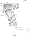
- a fluid powered machine 100 including a housing 102 and a fluid driven motor 104.
- the fluid powered device 100 can include a variety of fluid powered devices such as pumps, presses, hoists, grain elevators, or any other fluid powered device 100.
- the fluid powered device 100 can be a power tool including, but not limited to a drill, ratchet, chisel, grinder, or the like.
- the fluid powered device 100 is a handheld pneumatic tool which includes a hand grip 120.
- the motive fluid 114 can be any fluid capable powering the fluid driven motor 104.
- the motive fluid 114 can be a compressible gas.
- Air 114 can be utilized as the motive fluid 114, which is received from a pressure source 116.
- the pressure source 116 can include various compressors, pistons, pressurized tanks, or any other device which is capable of exerting or retaining pressure on the motive fluid 114.
- the pressure source 116 is an oil free screw air compressor.
- the fluid driven motor 104 can be any device which is capable of extracting energy from the motive fluid 114 and being driven thereby.
- the fluid driven motor 104 can be a piston, turbine, rotor, screw drive, or any other such device.
- the fluid driven motor 104 can be a turbine which converts the potential energy stored in the pressurized air 114 into rotational motion to be harnessed at a motor shaft output 122.
- a fluid inlet 106 allows the motive fluid 114 to flow into a valve assembly 108.
- the fluid inlet 106 may include various flanges, fittings, etc., on an end opposite the valve assembly 108, to provide ease of coupling with respect to the pressure source 116.
- the housing 102 can include a pressure chamber 118 to store a portion of motive fluid 114 to ensure consistent flow to the valve assembly 108.
- the valve assembly 108 is operated by an actuator 110.
- the actuator 110 can take a variety of forms including, but not limited to, electronic or manual actuators such as linear actuators, hydraulic actuators, motor driven actuators, solenoids, or the like.
- the actuator 110 can receive an input from a location near the actuator, such as is illustrated in Fig. 1 , or can receive an input signal from a distant location such as a push button (not shown) for use with a pneumatic hoist, as one non-limiting example.
- the actuator 110 can be a trigger 110 which provides a mechanical force to the valve assembly 108.
- the valve assembly 108 permits the selective release of the motive fluid 114 from the fluid inlet 106 to an inlet 112 of the fluid driven motor 104.
- the valve assembly 108 includes at least one plunger 202.
- the plunger 202 includes a plurality of axially extending fluid channels 204, 208, 212 located in a plunger body 214.
- the axially extending fluid channels 204, 208, 212 can be grooves in the plunger body 214, apertures extending within the plunger body 214 and having an intake 206, 210, or can be any other passageway which permits the flow of fluid from an intake 206, 210 of the axially extending fluid channel 204 to an exit of the axially extending fluid channel 204, wherein the exit is in flow communication with the fluid driven motor 104.
- Each of the plurality of axially extending fluid channels 204, 208, 212 includes a fluid intake 206, 210, 306.
- the fluid intakes 206, 210, 306 are disposed axially in relation to each of the other fluid intakes 206, 210, 306.
- An axis 220 is a reference axis for use in describing axial relationships as well as movement along an axis; however, the axial relationships and axial movements are not meant to be limited by axis 220.
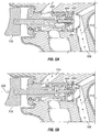
- the fluid intakes 206, 210, 306 and corresponding axially extending channels 204, 208, 212 can be disposed circumferentially with relation to each other as is illustrated in Fig. 2B .
- any number of axially extending fluid channels can be incorporated into the plunger body 214 depending upon the specific application, manufacturing capabilities, and any cost to benefit analysis associated therewith. As will be explained below, the number of axially extending fluid channels can determine the number of speeds at which the fluid driven motor 104 can operate.
- Fig. 3 illustrates a plunger assembly 300 including five axially extending channels 204, 208, 212, 310, 314 and corresponding intakes 206, 210, 306, 308, 312.
- the plunger body 214 is capable of providing five different fluid flows to the fluid driven motor 104; therefore, driving the fluid driven motor 104 at five different speeds.
- the plunger assembly 300 includes a plurality of sealing members 302 and 304 meant to segregate the inlet 106 from the inlet 112 of the fluid driven motor 104.
- the sealing members 302 and 304 can be O-rings, gaskets, or any other devices capable of performing a sealing or semi-sealing function, depending on the specific application.
- the sealing members 302 and/or 304 can be incorporated into various wall members or other housing structures of the valve assembly 108, can be incorporated into one or more plungers, or the one or more plungers can themselves form the sealing members 302 and/or 304.
- the first intake 206 of the axially extending channel 204 is placed in fluid communication with the fluid inlet 106.
- the second intake 210 is placed in fluid communication with the fluid inlet 106.
- the motive fluid 114 can pass from the fluid inlet 106 through the fluid intakes 206 and 210, traversing the axially extending fluid channels 204, 208, and enter the fluid driven motor 104 through the inlet 112 of the fluid driven motor 104.
- the remainder of the intakes 306, 308, and 314 have not been placed in fluid communication with the fluid inlet 106 as the sealing member 302 prevents the motive fluid 114 from entering therein. Therefore, in this illustration, the motor 204 is only receiving motive fluid 114 from two of a potential five channels.
- the valve assembly 108 can include more than one plunger.
- Fig. 4 illustrates a cut away view 400 of the valve assembly 108 including a second plunger 404.
- the second plunger 404 can be located around the first plunger 202. Upon full displacement of the first plunger 202, the second plunger 404 can be displaced, providing a maximum motive fluid 114 flow.
- the second plunger 404 can additionally or alternatively contain a plurality of axially extending fluid channels through which the motive fluid 114 traverses upon the linear displacement of the second plunger 404, as was discussed with reference to the first plunger 202. In providing the second plunger 404 with a plurality of axially extending fluid channels, the number of total fluid driven motor 104 speeds can be increased.
- Fig. 4 illustrates that a portion of the fluid inlet 106 and an inlet 402 of the valve assembly 108 can be disposed in a perpendicular or approximately perpendicular relationship. However, any configuration with relation to fluid inlet 106 and inlet 402 can be utilized depending upon the specific application and flow desired.
- valve assembly 108 various illustrative modes of valve assembly 108 operation will be discussed.
- the trigger 110 is not depressed and the plunger 202 is located at a first position 502.
- a manual force 506 is exerted on the trigger such that the first plunger 202 is moved from the first position 502 to a second position 504 wherein the motive fluid 114, received from the fluid inlet 106, enters a first axially extending fluid channel 204, and the motive fluid 114 is directed to the fluid driven motor 104.
- the plunger 202 is directed to a third position where a second axially extending fluid channel 208 is also placed in flow communication with the fluid inlet 106.
- n is the total number of channels disposed in the plunger body 214.
- the axially extending fluid channel corresponding to the respective position is placed in flow communication with the fluid inlet 106, and the motive fluid 114 traverses the respective axially extending fluid channel and is directed toward the fluid driven motor 104.
- the total motive fluid 114 flow directed toward the fluid driven motor 104 is the combined total of the motive fluid 114 flows through each of the axially extending fluid channels 204, 208, n th which are in flow communication with the fluid inlet 106. Therefore, the greater the number of axially extending fluid channels, the greater the number of speeds at which the fluid driven motor 104 can potentially be operated.
- the second plunger 404 can be axially displaced by the actuator 110.
- the motive fluid 114 is traversing all of the axially extending fluid channels in the first plunger 202
- continued depression 602 of the trigger 110 can result in linear movement of the second plunger 404 to an open position 604.
- the second plunger 404 can be displaced directly by the actuator 110, or via relative motion of the first plunger 202 relative the second plunger 404.
- the second plunger 404 can be displaced by a protrusion 606 extending from the first plunger.
- the linear movement of the second plunger 404 can result in a fully open position of the valve assembly 108, thereby permitting a maximum flow of the motive fluid 114 to the fluid driven motor 104.
- the second plunger 404 can additionally have a plurality of axially extending channels, wherein displacement of the second plunger to a first through n th position places a first through n th axially extending channel in flow communication with the fluid inlet 106, as was previously discussed with reference to the first plunger 202.
Landscapes
- Engineering & Computer Science (AREA)
- Mechanical Engineering (AREA)
- General Engineering & Computer Science (AREA)
- Details Of Reciprocating Pumps (AREA)
- Hydraulic Motors (AREA)
Claims (12)
- System, umfassend:eine Einlassöffnung für ein fließendes Medium (106), die mit einer Druckquelle (116) verbunden werden kann, um ein Treibmedium (114) zuzuführen;einen hydraulisch angetriebenen Motor (104), der so konstruiert wurde, dass er durch die Wirkung des Treibmediums (114) in einer Antriebsrichtung mit variablen Geschwindigkeiten angetrieben wird, wobei der hydraulisch angetriebene Motor (104) eine Einlassöffnung (112) zur Aufnahme des Treibmediums (114) aufweist; undeine Ventilbaugruppe (108), die von der Einlassöffnung für das fließende Medium (106) bis zur Einlassöffnung (112) die selektive Freigabe des Treibmediums (114) des hydraulisch angetriebenen Motors ermöglicht und dadurch gekennzeichnet ist, dass die Ventilbaugruppe (108) eine Vielzahl von Dichtungselementen (302, 304) aufweist, um die Einlassöffnung für das fließende Medium (106) selektiv von der Einlassöffnung (112) des hydraulisch angetriebenen Motors (104) zu trennen und eine Vielzahl von Fluidkanälen (204, 208, 212, 310, 314), die durch die Bewegung eines ersten Kolbens (202) derart freigelegt werden, dass das Treibmedium (114) an einem der Dichtungselemente (302, 304) vorbei in den hydraulisch angetriebenen Motor (104) strömen kann, wobei der erste Kolben (202) in verschiedene Positionen (502, 504) bewegt werden kann, um selektiv einen oder mehrere der vielen Fluidkanäle (204, 208, 212, 310, 314) zur Beförderung des Treibmediums (114) freizulegen und als Folge der Freigabe der Fluidkanäle (204, 208, 212, 310, 314) das Treibmedium (114) mit variabler Durchflussmenge durch die Ventilbaugruppe (108) zu befördern, wobei die variable Durchflussmenge des Treibmediums (114) beim hydraulisch angetriebenen Motor (104) eine variable Geschwindigkeit erzeugt.
- System gemäß Anspruch 1, wobei der erste Kolben (202) ein erster verschiebbarer Kolben ist, der ferner einen so konstruierten Stellantrieb (110) aufweist, dass er den ersten verschiebbaren Kolben (202) von einer ersten Position (502) in eine zweite Position (504) verschieben kann.
- System gemäß Anspruch 2, wobei der erste Kolben (202) ein Gebilde aufweist, das eine Vielzahl von Fluidkanälen (204, 208, 212, 310, 314) bildet.
- System gemäß Anspruch 2, ferner umfassend einen zweiten Kolben (404), der durch den Stellantrieb (110) selektiv verschoben werden kann, wobei der zweite Kolben (404) so konstruiert ist, dass neben dem durch den ersten verschiebbaren Kolben (202) bereitgestellten Treibmedium (114) zusätzliches Treibmedium (114) zum hydraulisch angetriebenen Motor (104) fließen kann.
- System gemäß Anspruch 4, wobei die vom hydraulisch angetriebenen Motor (104) aufgrund der Verlagerung des zweiten Kolbens (404) aufgenommene Fluidströmung die Fluidströmung überschreitet, die vom hydraulisch angetriebenen Motor (104) aufgrund der Verlagerung des ersten Kolbens (202) aufgenommen wird oder wobei die Vielzahl der Fluidkanäle (204, 208, 212, 310, 314) sich axial erstreckende Fluidkanäle (204, 208, 212, 310, 314) sind und wobei jeder der Vielzahl der sich axial erstreckenden Fluidkanäle (204, 208, 212, 310, 314) gegenüber dem benachbarten Fluidkanal (204, 208, 212, 310, 314) axial so versetzt angeordnet ist, dass die versetzte Anordnung die selektive Freilegung der Fluidkanäle (204, 208, 212, 310, 314) ermöglicht, wenn der erste verschiebbare Kolben (202) zwischen einer ersten Position (502) und einer zweiten Position (504) verschoben wird.
- System gemäß Anspruch 5, wobei die Vielzahl von Fluidkanälen mindestens drei sich axial erstreckende Fluidkanäle (204, 208, 212, 310, 314) umfasst.
- System gemäß Anspruch 2, ferner umfassend ein Gehäuse (102), das mindestens einen Teil eines mit Druckluft angetriebenen Werkzeugs (100) definiert, wobei das Gehäuse (102) den hydraulisch angetriebenen Motor (104) und die Ventilbaugruppe (108) umfasst und wobei der zur Positionsänderung (502, 504) des ersten Kolbens (202) verwendete Stellantrieb (110) ein Auslöser ist.
- System gemäß Anspruch 1, ferner umfassend einen so konstruierten zweiten Kolben (404), dass er zusätzlich zu der durch den ersten Kolben (202) erzeugten Strömung einen Strömungsdurchgangsbereich für das Treibmedium (114) bereitstellt, wobei der zweite Kolben (404) durch die Bewegung des ersten Kolbens (202) betätigt wird.
- System gemäß Anspruch 1, wobei die Ventilbaugruppe (108) so konstruiert ist, dass sie strömungstechnisch mit einer Fluiddruckbeaufschlagungsquelle (116) verbunden ist und wobei die Fluiddruckbeaufschlagungsquelle (116) ein Luftkompressor ist.
- Verfahren, umfassend:
einem hydraulisch angetriebenen Motor (104) über eine Ventilbaugruppe mit variabler Geschwindigkeit (108) durch eine mit einer Druckquelle (116) verbundene Einlassöffnung für ein fließendes Medium (106) ein Treibmedium (114) zuführen, wobei die Ventilbaugruppe mit variabler Geschwindigkeit (108) das Treibmedium von der Einlassöffnung für das fließende Medium (106) bis zur Einlassöffnung (112) des hydraulisch angetriebenen Motors (104) selektiv freisetzen kann, wobei die Ventilbaugruppe mit variabler Geschwindigkeit (108) eine Vielzahl von Dichtungselementen (302, 304) aufweist, um die Einlassöffnung für das fließende Medium (106) von der Einlassöffnung (112) des hydraulisch angetriebenen Motors (104) zu trennen und eine Vielzahl von versetzten Strömungskanälen (204, 208, 212, 310, 314), durch die Bewegung des beweglichen ersten Kolbens (202) selektiv freizulegen, wobei das Zusammenwirken der Vielzahl von Dichtungselementen (302, 304) mit dem beweglichen ersten Kolben (202) die geschlossenen Positionen der vielen versetzten Strömungskanäle (204, 208, 212, 310, 314) und die betriebsmäßig geöffnete Positionen der Vielzahl von versetzten Strömungskanälen (204, 208, 212, 310, 314) bilden, wobei dieser Vorgang umfasst:den ersten Kolben (202) in eine erste betriebsmäßig geöffnete Position bewegen, um den ersten der Vielzahl von versetzten Strömungskanälen (204, 208, 212, 310, 314) freizulegen, damit das Treibmedium (114) an einem Dichtungselemente (302, 304) vorbeiströmen und den ersten der Vielzahl von versetzten Strömungskanälen (204, 208, 212, 310, 314) durchfließen kann;das Treibmedium (114) durch den ersten der Vielzahl von versetzten Strömungskanälen (204, 208, 212, 310, 314) fließen lassen, damit das Treibmedium (114) einem hydraulisch angetriebenen Motor (104) zugeführt und der Motor (104) mit einer ersten Geschwindigkeit angetrieben werden kann;den zweiten Kolben (202) in eine zweite betriebsmäßig geöffnete Position bewegen, um den ersten der Vielzahl von versetzten Strömungskanälen (204, 208, 212, 310, 314) freizulegen, damit das Treibmedium (114) an dem einen der Dichtungselemente (302, 304) vorbeiströmen und den ersten der Vielzahl von versetzten Strömungskanälen und den zweiten der Vielzahl von versetzten Strömungskanälen durchfließen kann;das Treibmedium (114) durch den ersten der Vielzahl von versetzten Strömungskanälen (204, 208, 212, 310, 314) und den zweiten der Vielzahl von versetzten Strömungskanälen (204, 208, 212, 310, 314) fließen lassen, damit das Treibmedium (114) einem hydraulisch angetriebenen Motor (104) zugeführt und der Motor (104) mit einer zweiten und schnelleren als der ersten Geschwindigkeit angetrieben werden kann; - Verfahren gemäß Anspruch 10, ferner umfassend den ersten Kolben (202) in eine Vielzahl von Betriebspositionen versetzen, wobei jede Betriebsposition einer Position entspricht, an der ein anderer versetzter Strömungskanal (204, 208, 212, 310, 314) Treibmedium (114) in den hydraulisch angetriebenen Motor (104) strömen lässt, wobei sich die Drehzahl des Motors (104) erhöht, wenn sich die Anzahl der versetzten Strömungskanäle (204, 208, 212, 310, 314) erhöht, durch die das Treibmedium (114) fließen kann oder ferner umfasst, die Treibmediumströmung (114) im Gehäuse (102) eines Werkzeugs (100) mit einem hydraulisch angetriebenen Motor (104) von einer ersten Einlassrichtung in der Ventilbaugruppe (108) in eine zweite Richtung zu wechseln, wobei die erste Einlassrichtung ungefähr senkrecht zur zweiten Richtung verläuft.
- Verfahren gemäß Anspruch 11, ferner umfassend den ersten Kolben (202) in eine Betriebsposition verlagern, damit alle der Vielzahl von versetzten Strömungskanälen (204, 208, 212, 310, 314) Treibmedium (114) befördern können und einen zweiten Kolben (404) in eine Betriebsposition verlagern, um die Treibmediumströmung (114) durch die Vielzahl von versetzten Strömungskanälen (204, 208, 212, 310, 314) zu verstärken, wobei sich die Geschwindigkeit des Motors (104) erhöht, wenn der zweite Kolben verschoben wird (404).
Applications Claiming Priority (2)
| Application Number | Priority Date | Filing Date | Title |
|---|---|---|---|
| US201261679038P | 2012-08-02 | 2012-08-02 | |
| PCT/US2013/053494 WO2014022812A1 (en) | 2012-08-02 | 2013-08-02 | Variable speed control of fluid driven motors |
Publications (3)
| Publication Number | Publication Date |
|---|---|
| EP2879826A1 EP2879826A1 (de) | 2015-06-10 |
| EP2879826A4 EP2879826A4 (de) | 2016-08-03 |
| EP2879826B1 true EP2879826B1 (de) | 2018-10-03 |
Family
ID=50024360
Family Applications (1)
| Application Number | Title | Priority Date | Filing Date |
|---|---|---|---|
| EP13824748.1A Not-in-force EP2879826B1 (de) | 2012-08-02 | 2013-08-02 | Steuerung fluidbetätigter motoren mit variabler geschwindigkeit |
Country Status (4)
| Country | Link |
|---|---|
| US (2) | US9687978B2 (de) |
| EP (1) | EP2879826B1 (de) |
| CN (1) | CN104903038B (de) |
| WO (1) | WO2014022812A1 (de) |
Families Citing this family (6)
| Publication number | Priority date | Publication date | Assignee | Title |
|---|---|---|---|---|
| EP2879826B1 (de) * | 2012-08-02 | 2018-10-03 | Ingersoll-Rand Company | Steuerung fluidbetätigter motoren mit variabler geschwindigkeit |
| TWI477362B (zh) * | 2014-04-28 | 2015-03-21 | Tranmax Machinery Co Ltd | A single tool is used to switch the pneumatic tool that reverses and adjusts the speed |
| US10328564B2 (en) * | 2015-02-27 | 2019-06-25 | Snap-On Incorporated | Controlling incoming air for a multi-directional rotational motor in a single rotational direction |
| US11654597B1 (en) * | 2019-04-16 | 2023-05-23 | Jeff Leserra | Handheld hydraulic-powered concrete-cutting handsaw |
| US12304108B1 (en) * | 2019-04-16 | 2025-05-20 | Jeffrey Leserra | Handheld hydraulic-powered concrete-cutting handsaw |
| CN112901477B (zh) * | 2021-03-31 | 2025-10-03 | 烟台杰瑞石油装备技术有限公司 | 柱塞、液力端和柱塞泵 |
Family Cites Families (36)
| Publication number | Priority date | Publication date | Assignee | Title |
|---|---|---|---|---|
| US2995114A (en) * | 1959-01-29 | 1961-08-08 | Henry J Starr | Stapler valve |
| US3326240A (en) * | 1964-08-03 | 1967-06-20 | Skil Corp | Regulator and control for a fluid operated device |
| US3298284A (en) | 1964-09-11 | 1967-01-17 | Rockwell Mfg Co | Servo operated reversing tool |
| GB1306927A (en) * | 1969-03-17 | 1973-02-14 | Broom & Wade Ltd | Control means for reversible fluid pressure operated rotary motors |
| US3590875A (en) * | 1969-12-08 | 1971-07-06 | Oren V Northcutt | Air motor valve |
| US3696834A (en) * | 1971-01-29 | 1972-10-10 | Thor Power Tool Co | Fluid control device |
| US3970110A (en) * | 1975-02-06 | 1976-07-20 | Chicago Pneumatic Tool Company | Safety inlet air valve control arrangement for air powered hand held tool |
| US4024892A (en) * | 1976-03-08 | 1977-05-24 | Microdot, Inc. | Valve for use in a nut installation tool |
| US4380270A (en) * | 1981-01-23 | 1983-04-19 | Allan Air Products, Inc. | Tool device |
| US4476942A (en) * | 1982-04-28 | 1984-10-16 | Monogram Industries, Inc. | Variable speed inlet control valve |
| US5417294A (en) * | 1994-03-15 | 1995-05-23 | American Pneumatic Technologies | Pneumatic hammer |
| SE503847C2 (sv) * | 1994-10-10 | 1996-09-16 | Atlas Copco Tools Ab | Handtag till ett pneumatiskt kraftverktyg |
| US5918686A (en) | 1997-06-24 | 1999-07-06 | S.P. Air Kabusiki Kaisha | Pneumatic rotary tool |
| US6443239B1 (en) * | 2000-02-29 | 2002-09-03 | S.P. Air Kabusiki Kaisha | Pneumatic rotary tool |
| US6161628A (en) | 2000-04-28 | 2000-12-19 | Q.C. Witness Int. Co., Ltd. | Pneumatic tool |
| SE525018C2 (sv) | 2003-03-21 | 2004-11-09 | Parker Hannifin Ab | Anordning för styrning av en hydrauliskt driven motor |
| US6902011B2 (en) * | 2003-05-23 | 2005-06-07 | Fci Americas Technology, Inc. | Variable torque impact wrench |
| US7537027B2 (en) * | 2003-11-24 | 2009-05-26 | Campbell Hausfeld/Scott Fetzer Company | Valve with duel outlet ports |
| CN1295441C (zh) | 2004-11-05 | 2007-01-17 | 宁波华液机器制造有限公司 | 一种比例压差控制阀 |
| JP4487856B2 (ja) * | 2005-05-30 | 2010-06-23 | 日立工機株式会社 | エア工具 |
| TWI266679B (en) | 2005-06-29 | 2006-11-21 | Basso Ind Corp | Improved mechanism of switching position for user by right or left hand about CW-CCW valve in a pneumatic tool |
| US7311155B2 (en) | 2005-12-13 | 2007-12-25 | Mighty Seven International Co., Ltd. | Pneumatic tool with direction switch operable with single hand |
| US7373992B2 (en) * | 2006-07-26 | 2008-05-20 | Exhaust Technologies, Inc. | Automatic pressure regulating valve for a pneumatic tool |
| US7461704B2 (en) * | 2007-03-19 | 2008-12-09 | Sunmatch Industrial Co., Ltd. | Airflow control structure for pneumatic tools |
| US8201580B2 (en) | 2008-01-14 | 2012-06-19 | Sti Srl | High flow capacity positioner |
| FR2927010B1 (fr) * | 2008-01-31 | 2010-06-11 | Sullair Europ | Dispositif de marteau piqueur a air comprime |
| US8122907B2 (en) * | 2008-05-05 | 2012-02-28 | Ingersoll-Rand Company | Motor assembly for pneumatic tool |
| US7886840B2 (en) | 2008-05-05 | 2011-02-15 | Ingersoll-Rand Company | Motor assembly for pneumatic tool |
| US8020630B2 (en) * | 2009-05-29 | 2011-09-20 | Ingersoll Rand Company | Swinging weight assembly for impact tool |
| JP5547004B2 (ja) | 2010-09-07 | 2014-07-09 | 瓜生製作株式会社 | 油圧式トルクレンチの打撃トルク調節装置 |
| CN202148555U (zh) | 2011-06-24 | 2012-02-22 | 安徽金达利液压有限公司 | 一种控制结构 |
| US9604355B2 (en) * | 2011-09-30 | 2017-03-28 | Textron Innovations Inc. | Handle for a hydraulically driven tool with heat transmission reducing properties |
| TW201347928A (zh) * | 2012-05-30 | 2013-12-01 | Basso Ind Corp | 具有保險裝置的氣動工具 |
| EP2879826B1 (de) * | 2012-08-02 | 2018-10-03 | Ingersoll-Rand Company | Steuerung fluidbetätigter motoren mit variabler geschwindigkeit |
| US9555532B2 (en) | 2013-07-01 | 2017-01-31 | Ingersoll-Rand Company | Rotary impact tool |
| TWI526284B (zh) * | 2014-09-16 | 2016-03-21 | De Poan Pneumatic Corp | Pneumatic rotary tool intake control valve group |
-
2013
- 2013-08-02 EP EP13824748.1A patent/EP2879826B1/de not_active Not-in-force
- 2013-08-02 WO PCT/US2013/053494 patent/WO2014022812A1/en not_active Ceased
- 2013-08-02 CN CN201380051684.1A patent/CN104903038B/zh not_active Expired - Fee Related
- 2013-08-02 US US13/958,321 patent/US9687978B2/en not_active Expired - Fee Related
- 2013-08-02 US US13/958,317 patent/US9789599B2/en not_active Expired - Fee Related
Non-Patent Citations (1)
| Title |
|---|
| None * |
Also Published As
| Publication number | Publication date |
|---|---|
| WO2014022812A1 (en) | 2014-02-06 |
| US20140034349A1 (en) | 2014-02-06 |
| CN104903038B (zh) | 2018-12-25 |
| US20140034345A1 (en) | 2014-02-06 |
| EP2879826A1 (de) | 2015-06-10 |
| EP2879826A4 (de) | 2016-08-03 |
| US9687978B2 (en) | 2017-06-27 |
| US9789599B2 (en) | 2017-10-17 |
| CN104903038A (zh) | 2015-09-09 |
Similar Documents
| Publication | Publication Date | Title |
|---|---|---|
| US9687978B2 (en) | Variable speed control of fluid driven motors | |
| KR101262772B1 (ko) | 감압 스위칭 밸브 | |
| EP2714340B1 (de) | Hydrodynamisches werkzeug, hydraulikpumpe und mechanismus zur umwandlung einer drehbewegung in eine oszillierende translationsbewegung für ein solches werkzeug | |
| FI116513B (fi) | Iskulaite | |
| CN103930673B (zh) | 斜板式活塞泵 | |
| KR102298471B1 (ko) | 유압 펌프 | |
| US3687008A (en) | Pressure fluid controlled reciprocating mechanism | |
| EP2012977B1 (de) | Pneumatisch bedienbares eintreibwerkzeug sowie betriebsverfahren dafür | |
| EP2758674B1 (de) | Sparvorrichtung für pneumatischen linearaktor | |
| KR20110074018A (ko) | 모터구동 파워피스톤 | |
| EP3209884B1 (de) | Luftmotor | |
| EP2871371B1 (de) | Schalteinheit, hydraulische Maschine und Stromerzeugungsvorrichtung | |
| CN209943015U (zh) | 增压泵 | |
| EP3009619B1 (de) | Gasawechselsventilaktuator zur axialverschiebung eines gaswechselsventils eines verbrennungsmotors | |
| CN1223766C (zh) | 液压撞击/冲压装置 | |
| MX2008016413A (es) | Bomba hidraulica. | |
| CN107110391B (zh) | 电磁阀歧管 | |
| US5324173A (en) | High pressure intensifier | |
| EP2133556A1 (de) | Verbesserungen für den betrieb eines druckgenerators | |
| KR101811422B1 (ko) | 유체 모터 | |
| KR101705586B1 (ko) | 유체 모터 | |
| CN110834305B (zh) | 一种气动工具 | |
| US6487957B2 (en) | Fluid-operated cylinder providing linear and rotary motion | |
| CN111051005A (zh) | 具有冲击接合器的扭矩扳手 | |
| JP2018193889A (ja) | 空気圧複動式ポンプ |
Legal Events
| Date | Code | Title | Description |
|---|---|---|---|
| PUAI | Public reference made under article 153(3) epc to a published international application that has entered the european phase |
Free format text: ORIGINAL CODE: 0009012 |
|
| 17P | Request for examination filed |
Effective date: 20150302 |
|
| AK | Designated contracting states |
Kind code of ref document: A1 Designated state(s): AL AT BE BG CH CY CZ DE DK EE ES FI FR GB GR HR HU IE IS IT LI LT LU LV MC MK MT NL NO PL PT RO RS SE SI SK SM TR |
|
| AX | Request for extension of the european patent |
Extension state: BA ME |
|
| DAX | Request for extension of the european patent (deleted) | ||
| RA4 | Supplementary search report drawn up and despatched (corrected) |
Effective date: 20160630 |
|
| RIC1 | Information provided on ipc code assigned before grant |
Ipc: B23B 45/04 20060101AFI20160624BHEP Ipc: B25F 5/00 20060101ALI20160624BHEP Ipc: F01C 13/02 20060101ALI20160624BHEP Ipc: F01C 21/18 20060101ALI20160624BHEP Ipc: F01C 20/08 20060101ALI20160624BHEP |
|
| STAA | Information on the status of an ep patent application or granted ep patent |
Free format text: STATUS: EXAMINATION IS IN PROGRESS |
|
| 17Q | First examination report despatched |
Effective date: 20170223 |
|
| GRAP | Despatch of communication of intention to grant a patent |
Free format text: ORIGINAL CODE: EPIDOSNIGR1 |
|
| STAA | Information on the status of an ep patent application or granted ep patent |
Free format text: STATUS: GRANT OF PATENT IS INTENDED |
|
| INTG | Intention to grant announced |
Effective date: 20180226 |
|
| GRAS | Grant fee paid |
Free format text: ORIGINAL CODE: EPIDOSNIGR3 |
|
| GRAA | (expected) grant |
Free format text: ORIGINAL CODE: 0009210 |
|
| STAA | Information on the status of an ep patent application or granted ep patent |
Free format text: STATUS: THE PATENT HAS BEEN GRANTED |
|
| AK | Designated contracting states |
Kind code of ref document: B1 Designated state(s): AL AT BE BG CH CY CZ DE DK EE ES FI FR GB GR HR HU IE IS IT LI LT LU LV MC MK MT NL NO PL PT RO RS SE SI SK SM TR |
|
| REG | Reference to a national code |
Ref country code: GB Ref legal event code: FG4D |
|
| REG | Reference to a national code |
Ref country code: CH Ref legal event code: EP Ref country code: AT Ref legal event code: REF Ref document number: 1048075 Country of ref document: AT Kind code of ref document: T Effective date: 20181015 |
|
| REG | Reference to a national code |
Ref country code: DE Ref legal event code: R096 Ref document number: 602013044593 Country of ref document: DE Ref country code: IE Ref legal event code: FG4D |
|
| REG | Reference to a national code |
Ref country code: NL Ref legal event code: MP Effective date: 20181003 |
|
| REG | Reference to a national code |
Ref country code: LT Ref legal event code: MG4D |
|
| REG | Reference to a national code |
Ref country code: AT Ref legal event code: MK05 Ref document number: 1048075 Country of ref document: AT Kind code of ref document: T Effective date: 20181003 |
|
| PG25 | Lapsed in a contracting state [announced via postgrant information from national office to epo] |
Ref country code: NL Free format text: LAPSE BECAUSE OF FAILURE TO SUBMIT A TRANSLATION OF THE DESCRIPTION OR TO PAY THE FEE WITHIN THE PRESCRIBED TIME-LIMIT Effective date: 20181003 |
|
| PG25 | Lapsed in a contracting state [announced via postgrant information from national office to epo] |
Ref country code: FI Free format text: LAPSE BECAUSE OF FAILURE TO SUBMIT A TRANSLATION OF THE DESCRIPTION OR TO PAY THE FEE WITHIN THE PRESCRIBED TIME-LIMIT Effective date: 20181003 Ref country code: IS Free format text: LAPSE BECAUSE OF FAILURE TO SUBMIT A TRANSLATION OF THE DESCRIPTION OR TO PAY THE FEE WITHIN THE PRESCRIBED TIME-LIMIT Effective date: 20190203 Ref country code: BG Free format text: LAPSE BECAUSE OF FAILURE TO SUBMIT A TRANSLATION OF THE DESCRIPTION OR TO PAY THE FEE WITHIN THE PRESCRIBED TIME-LIMIT Effective date: 20190103 Ref country code: LT Free format text: LAPSE BECAUSE OF FAILURE TO SUBMIT A TRANSLATION OF THE DESCRIPTION OR TO PAY THE FEE WITHIN THE PRESCRIBED TIME-LIMIT Effective date: 20181003 Ref country code: NO Free format text: LAPSE BECAUSE OF FAILURE TO SUBMIT A TRANSLATION OF THE DESCRIPTION OR TO PAY THE FEE WITHIN THE PRESCRIBED TIME-LIMIT Effective date: 20190103 Ref country code: CZ Free format text: LAPSE BECAUSE OF FAILURE TO SUBMIT A TRANSLATION OF THE DESCRIPTION OR TO PAY THE FEE WITHIN THE PRESCRIBED TIME-LIMIT Effective date: 20181003 Ref country code: AT Free format text: LAPSE BECAUSE OF FAILURE TO SUBMIT A TRANSLATION OF THE DESCRIPTION OR TO PAY THE FEE WITHIN THE PRESCRIBED TIME-LIMIT Effective date: 20181003 Ref country code: ES Free format text: LAPSE BECAUSE OF FAILURE TO SUBMIT A TRANSLATION OF THE DESCRIPTION OR TO PAY THE FEE WITHIN THE PRESCRIBED TIME-LIMIT Effective date: 20181003 Ref country code: HR Free format text: LAPSE BECAUSE OF FAILURE TO SUBMIT A TRANSLATION OF THE DESCRIPTION OR TO PAY THE FEE WITHIN THE PRESCRIBED TIME-LIMIT Effective date: 20181003 Ref country code: PL Free format text: LAPSE BECAUSE OF FAILURE TO SUBMIT A TRANSLATION OF THE DESCRIPTION OR TO PAY THE FEE WITHIN THE PRESCRIBED TIME-LIMIT Effective date: 20181003 Ref country code: LV Free format text: LAPSE BECAUSE OF FAILURE TO SUBMIT A TRANSLATION OF THE DESCRIPTION OR TO PAY THE FEE WITHIN THE PRESCRIBED TIME-LIMIT Effective date: 20181003 |
|
| PG25 | Lapsed in a contracting state [announced via postgrant information from national office to epo] |
Ref country code: PT Free format text: LAPSE BECAUSE OF FAILURE TO SUBMIT A TRANSLATION OF THE DESCRIPTION OR TO PAY THE FEE WITHIN THE PRESCRIBED TIME-LIMIT Effective date: 20190203 Ref country code: AL Free format text: LAPSE BECAUSE OF FAILURE TO SUBMIT A TRANSLATION OF THE DESCRIPTION OR TO PAY THE FEE WITHIN THE PRESCRIBED TIME-LIMIT Effective date: 20181003 Ref country code: SE Free format text: LAPSE BECAUSE OF FAILURE TO SUBMIT A TRANSLATION OF THE DESCRIPTION OR TO PAY THE FEE WITHIN THE PRESCRIBED TIME-LIMIT Effective date: 20181003 Ref country code: RS Free format text: LAPSE BECAUSE OF FAILURE TO SUBMIT A TRANSLATION OF THE DESCRIPTION OR TO PAY THE FEE WITHIN THE PRESCRIBED TIME-LIMIT Effective date: 20181003 Ref country code: GR Free format text: LAPSE BECAUSE OF FAILURE TO SUBMIT A TRANSLATION OF THE DESCRIPTION OR TO PAY THE FEE WITHIN THE PRESCRIBED TIME-LIMIT Effective date: 20190104 |
|
| REG | Reference to a national code |
Ref country code: DE Ref legal event code: R097 Ref document number: 602013044593 Country of ref document: DE |
|
| PG25 | Lapsed in a contracting state [announced via postgrant information from national office to epo] |
Ref country code: IT Free format text: LAPSE BECAUSE OF FAILURE TO SUBMIT A TRANSLATION OF THE DESCRIPTION OR TO PAY THE FEE WITHIN THE PRESCRIBED TIME-LIMIT Effective date: 20181003 Ref country code: DK Free format text: LAPSE BECAUSE OF FAILURE TO SUBMIT A TRANSLATION OF THE DESCRIPTION OR TO PAY THE FEE WITHIN THE PRESCRIBED TIME-LIMIT Effective date: 20181003 |
|
| PLBE | No opposition filed within time limit |
Free format text: ORIGINAL CODE: 0009261 |
|
| STAA | Information on the status of an ep patent application or granted ep patent |
Free format text: STATUS: NO OPPOSITION FILED WITHIN TIME LIMIT |
|
| PG25 | Lapsed in a contracting state [announced via postgrant information from national office to epo] |
Ref country code: SM Free format text: LAPSE BECAUSE OF FAILURE TO SUBMIT A TRANSLATION OF THE DESCRIPTION OR TO PAY THE FEE WITHIN THE PRESCRIBED TIME-LIMIT Effective date: 20181003 Ref country code: EE Free format text: LAPSE BECAUSE OF FAILURE TO SUBMIT A TRANSLATION OF THE DESCRIPTION OR TO PAY THE FEE WITHIN THE PRESCRIBED TIME-LIMIT Effective date: 20181003 Ref country code: RO Free format text: LAPSE BECAUSE OF FAILURE TO SUBMIT A TRANSLATION OF THE DESCRIPTION OR TO PAY THE FEE WITHIN THE PRESCRIBED TIME-LIMIT Effective date: 20181003 Ref country code: SK Free format text: LAPSE BECAUSE OF FAILURE TO SUBMIT A TRANSLATION OF THE DESCRIPTION OR TO PAY THE FEE WITHIN THE PRESCRIBED TIME-LIMIT Effective date: 20181003 |
|
| 26N | No opposition filed |
Effective date: 20190704 |
|
| PG25 | Lapsed in a contracting state [announced via postgrant information from national office to epo] |
Ref country code: SI Free format text: LAPSE BECAUSE OF FAILURE TO SUBMIT A TRANSLATION OF THE DESCRIPTION OR TO PAY THE FEE WITHIN THE PRESCRIBED TIME-LIMIT Effective date: 20181003 |
|
| PGFP | Annual fee paid to national office [announced via postgrant information from national office to epo] |
Ref country code: DE Payment date: 20190722 Year of fee payment: 7 Ref country code: FR Payment date: 20190723 Year of fee payment: 7 |
|
| PGFP | Annual fee paid to national office [announced via postgrant information from national office to epo] |
Ref country code: GB Payment date: 20190722 Year of fee payment: 7 |
|
| PG25 | Lapsed in a contracting state [announced via postgrant information from national office to epo] |
Ref country code: TR Free format text: LAPSE BECAUSE OF FAILURE TO SUBMIT A TRANSLATION OF THE DESCRIPTION OR TO PAY THE FEE WITHIN THE PRESCRIBED TIME-LIMIT Effective date: 20181003 |
|
| PG25 | Lapsed in a contracting state [announced via postgrant information from national office to epo] |
Ref country code: CH Free format text: LAPSE BECAUSE OF NON-PAYMENT OF DUE FEES Effective date: 20190831 Ref country code: LI Free format text: LAPSE BECAUSE OF NON-PAYMENT OF DUE FEES Effective date: 20190831 Ref country code: LU Free format text: LAPSE BECAUSE OF NON-PAYMENT OF DUE FEES Effective date: 20190802 Ref country code: MC Free format text: LAPSE BECAUSE OF FAILURE TO SUBMIT A TRANSLATION OF THE DESCRIPTION OR TO PAY THE FEE WITHIN THE PRESCRIBED TIME-LIMIT Effective date: 20181003 |
|
| REG | Reference to a national code |
Ref country code: BE Ref legal event code: MM Effective date: 20190831 |
|
| PG25 | Lapsed in a contracting state [announced via postgrant information from national office to epo] |
Ref country code: IE Free format text: LAPSE BECAUSE OF NON-PAYMENT OF DUE FEES Effective date: 20190802 |
|
| PG25 | Lapsed in a contracting state [announced via postgrant information from national office to epo] |
Ref country code: BE Free format text: LAPSE BECAUSE OF NON-PAYMENT OF DUE FEES Effective date: 20190831 |
|
| REG | Reference to a national code |
Ref country code: GB Ref legal event code: 732E Free format text: REGISTERED BETWEEN 20200806 AND 20200812 |
|
| REG | Reference to a national code |
Ref country code: DE Ref legal event code: R082 Ref document number: 602013044593 Country of ref document: DE Representative=s name: HASELTINE LAKE KEMPNER LLP, DE Ref country code: DE Ref legal event code: R081 Ref document number: 602013044593 Country of ref document: DE Owner name: INGERSOLL-RAND INDUSTRIAL U.S., INC. (N.D.GES., US Free format text: FORMER OWNER: INGERSOLL-RAND COMPANY, DAVIDSON, N.C., US Ref country code: DE Ref legal event code: R082 Ref document number: 602013044593 Country of ref document: DE Representative=s name: HL KEMPNER PATENTANWALT, RECHTSANWALT, SOLICIT, DE |
|
| REG | Reference to a national code |
Ref country code: DE Ref legal event code: R082 Ref document number: 602013044593 Country of ref document: DE Representative=s name: HL KEMPNER PATENTANWALT, RECHTSANWALT, SOLICIT, DE |
|
| REG | Reference to a national code |
Ref country code: DE Ref legal event code: R119 Ref document number: 602013044593 Country of ref document: DE |
|
| GBPC | Gb: european patent ceased through non-payment of renewal fee |
Effective date: 20200802 |
|
| PG25 | Lapsed in a contracting state [announced via postgrant information from national office to epo] |
Ref country code: CY Free format text: LAPSE BECAUSE OF FAILURE TO SUBMIT A TRANSLATION OF THE DESCRIPTION OR TO PAY THE FEE WITHIN THE PRESCRIBED TIME-LIMIT Effective date: 20181003 |
|
| PG25 | Lapsed in a contracting state [announced via postgrant information from national office to epo] |
Ref country code: DE Free format text: LAPSE BECAUSE OF NON-PAYMENT OF DUE FEES Effective date: 20210302 Ref country code: MT Free format text: LAPSE BECAUSE OF FAILURE TO SUBMIT A TRANSLATION OF THE DESCRIPTION OR TO PAY THE FEE WITHIN THE PRESCRIBED TIME-LIMIT Effective date: 20181003 Ref country code: HU Free format text: LAPSE BECAUSE OF FAILURE TO SUBMIT A TRANSLATION OF THE DESCRIPTION OR TO PAY THE FEE WITHIN THE PRESCRIBED TIME-LIMIT; INVALID AB INITIO Effective date: 20130802 Ref country code: FR Free format text: LAPSE BECAUSE OF NON-PAYMENT OF DUE FEES Effective date: 20200831 |
|
| PG25 | Lapsed in a contracting state [announced via postgrant information from national office to epo] |
Ref country code: GB Free format text: LAPSE BECAUSE OF NON-PAYMENT OF DUE FEES Effective date: 20200802 |
|
| PG25 | Lapsed in a contracting state [announced via postgrant information from national office to epo] |
Ref country code: MK Free format text: LAPSE BECAUSE OF FAILURE TO SUBMIT A TRANSLATION OF THE DESCRIPTION OR TO PAY THE FEE WITHIN THE PRESCRIBED TIME-LIMIT Effective date: 20181003 |