EP2879820B1 - Maschine zur herstellung eines pulverförmigen zusatzstoffs - Google Patents
Maschine zur herstellung eines pulverförmigen zusatzstoffs Download PDFInfo
- Publication number
- EP2879820B1 EP2879820B1 EP13744538.3A EP13744538A EP2879820B1 EP 2879820 B1 EP2879820 B1 EP 2879820B1 EP 13744538 A EP13744538 A EP 13744538A EP 2879820 B1 EP2879820 B1 EP 2879820B1
- Authority
- EP
- European Patent Office
- Prior art keywords
- column
- machine
- machine according
- plate
- frame
- Prior art date
- Legal status (The legal status is an assumption and is not a legal conclusion. Google has not performed a legal analysis and makes no representation as to the accuracy of the status listed.)
- Active
Links
Images


Classifications
-
- B—PERFORMING OPERATIONS; TRANSPORTING
- B29—WORKING OF PLASTICS; WORKING OF SUBSTANCES IN A PLASTIC STATE IN GENERAL
- B29C—SHAPING OR JOINING OF PLASTICS; SHAPING OF MATERIAL IN A PLASTIC STATE, NOT OTHERWISE PROVIDED FOR; AFTER-TREATMENT OF THE SHAPED PRODUCTS, e.g. REPAIRING
- B29C64/00—Additive manufacturing, i.e. manufacturing of three-dimensional [3D] objects by additive deposition, additive agglomeration or additive layering, e.g. by 3D printing, stereolithography or selective laser sintering
- B29C64/10—Processes of additive manufacturing
- B29C64/141—Processes of additive manufacturing using only solid materials
- B29C64/153—Processes of additive manufacturing using only solid materials using layers of powder being selectively joined, e.g. by selective laser sintering or melting
-
- B—PERFORMING OPERATIONS; TRANSPORTING
- B22—CASTING; POWDER METALLURGY
- B22F—WORKING METALLIC POWDER; MANUFACTURE OF ARTICLES FROM METALLIC POWDER; MAKING METALLIC POWDER; APPARATUS OR DEVICES SPECIALLY ADAPTED FOR METALLIC POWDER
- B22F10/00—Additive manufacturing of workpieces or articles from metallic powder
- B22F10/20—Direct sintering or melting
- B22F10/28—Powder bed fusion, e.g. selective laser melting [SLM] or electron beam melting [EBM]
-
- B—PERFORMING OPERATIONS; TRANSPORTING
- B22—CASTING; POWDER METALLURGY
- B22F—WORKING METALLIC POWDER; MANUFACTURE OF ARTICLES FROM METALLIC POWDER; MAKING METALLIC POWDER; APPARATUS OR DEVICES SPECIALLY ADAPTED FOR METALLIC POWDER
- B22F10/00—Additive manufacturing of workpieces or articles from metallic powder
- B22F10/70—Recycling
- B22F10/73—Recycling of powder
-
- B—PERFORMING OPERATIONS; TRANSPORTING
- B22—CASTING; POWDER METALLURGY
- B22F—WORKING METALLIC POWDER; MANUFACTURE OF ARTICLES FROM METALLIC POWDER; MAKING METALLIC POWDER; APPARATUS OR DEVICES SPECIALLY ADAPTED FOR METALLIC POWDER
- B22F12/00—Apparatus or devices specially adapted for additive manufacturing; Auxiliary means for additive manufacturing; Combinations of additive manufacturing apparatus or devices with other processing apparatus or devices
- B22F12/22—Driving means
- B22F12/222—Driving means for motion along a direction orthogonal to the plane of a layer
-
- B—PERFORMING OPERATIONS; TRANSPORTING
- B22—CASTING; POWDER METALLURGY
- B22F—WORKING METALLIC POWDER; MANUFACTURE OF ARTICLES FROM METALLIC POWDER; MAKING METALLIC POWDER; APPARATUS OR DEVICES SPECIALLY ADAPTED FOR METALLIC POWDER
- B22F12/00—Apparatus or devices specially adapted for additive manufacturing; Auxiliary means for additive manufacturing; Combinations of additive manufacturing apparatus or devices with other processing apparatus or devices
- B22F12/30—Platforms or substrates
-
- B—PERFORMING OPERATIONS; TRANSPORTING
- B22—CASTING; POWDER METALLURGY
- B22F—WORKING METALLIC POWDER; MANUFACTURE OF ARTICLES FROM METALLIC POWDER; MAKING METALLIC POWDER; APPARATUS OR DEVICES SPECIALLY ADAPTED FOR METALLIC POWDER
- B22F12/00—Apparatus or devices specially adapted for additive manufacturing; Auxiliary means for additive manufacturing; Combinations of additive manufacturing apparatus or devices with other processing apparatus or devices
- B22F12/40—Radiation means
- B22F12/44—Radiation means characterised by the configuration of the radiation means
-
- B—PERFORMING OPERATIONS; TRANSPORTING
- B22—CASTING; POWDER METALLURGY
- B22F—WORKING METALLIC POWDER; MANUFACTURE OF ARTICLES FROM METALLIC POWDER; MAKING METALLIC POWDER; APPARATUS OR DEVICES SPECIALLY ADAPTED FOR METALLIC POWDER
- B22F12/00—Apparatus or devices specially adapted for additive manufacturing; Auxiliary means for additive manufacturing; Combinations of additive manufacturing apparatus or devices with other processing apparatus or devices
- B22F12/40—Radiation means
- B22F12/49—Scanners
-
- B—PERFORMING OPERATIONS; TRANSPORTING
- B22—CASTING; POWDER METALLURGY
- B22F—WORKING METALLIC POWDER; MANUFACTURE OF ARTICLES FROM METALLIC POWDER; MAKING METALLIC POWDER; APPARATUS OR DEVICES SPECIALLY ADAPTED FOR METALLIC POWDER
- B22F12/00—Apparatus or devices specially adapted for additive manufacturing; Auxiliary means for additive manufacturing; Combinations of additive manufacturing apparatus or devices with other processing apparatus or devices
- B22F12/50—Means for feeding of material, e.g. heads
- B22F12/52—Hoppers
-
- B—PERFORMING OPERATIONS; TRANSPORTING
- B22—CASTING; POWDER METALLURGY
- B22F—WORKING METALLIC POWDER; MANUFACTURE OF ARTICLES FROM METALLIC POWDER; MAKING METALLIC POWDER; APPARATUS OR DEVICES SPECIALLY ADAPTED FOR METALLIC POWDER
- B22F12/00—Apparatus or devices specially adapted for additive manufacturing; Auxiliary means for additive manufacturing; Combinations of additive manufacturing apparatus or devices with other processing apparatus or devices
- B22F12/50—Means for feeding of material, e.g. heads
- B22F12/57—Metering means
-
- B—PERFORMING OPERATIONS; TRANSPORTING
- B22—CASTING; POWDER METALLURGY
- B22F—WORKING METALLIC POWDER; MANUFACTURE OF ARTICLES FROM METALLIC POWDER; MAKING METALLIC POWDER; APPARATUS OR DEVICES SPECIALLY ADAPTED FOR METALLIC POWDER
- B22F12/00—Apparatus or devices specially adapted for additive manufacturing; Auxiliary means for additive manufacturing; Combinations of additive manufacturing apparatus or devices with other processing apparatus or devices
- B22F12/60—Planarisation devices; Compression devices
- B22F12/63—Rollers
-
- B—PERFORMING OPERATIONS; TRANSPORTING
- B29—WORKING OF PLASTICS; WORKING OF SUBSTANCES IN A PLASTIC STATE IN GENERAL
- B29L—INDEXING SCHEME ASSOCIATED WITH SUBCLASS B29C, RELATING TO PARTICULAR ARTICLES
- B29L2031/00—Other particular articles
- B29L2031/30—Vehicles, e.g. ships or aircraft, or body parts thereof
- B29L2031/3055—Cars
-
- B—PERFORMING OPERATIONS; TRANSPORTING
- B33—ADDITIVE MANUFACTURING TECHNOLOGY
- B33Y—ADDITIVE MANUFACTURING, i.e. MANUFACTURING OF THREE-DIMENSIONAL [3D] OBJECTS BY ADDITIVE DEPOSITION, ADDITIVE AGGLOMERATION OR ADDITIVE LAYERING, e.g. BY 3D PRINTING, STEREOLITHOGRAPHY OR SELECTIVE LASER SINTERING
- B33Y80/00—Products made by additive manufacturing
-
- Y—GENERAL TAGGING OF NEW TECHNOLOGICAL DEVELOPMENTS; GENERAL TAGGING OF CROSS-SECTIONAL TECHNOLOGIES SPANNING OVER SEVERAL SECTIONS OF THE IPC; TECHNICAL SUBJECTS COVERED BY FORMER USPC CROSS-REFERENCE ART COLLECTIONS [XRACs] AND DIGESTS
- Y02—TECHNOLOGIES OR APPLICATIONS FOR MITIGATION OR ADAPTATION AGAINST CLIMATE CHANGE
- Y02P—CLIMATE CHANGE MITIGATION TECHNOLOGIES IN THE PRODUCTION OR PROCESSING OF GOODS
- Y02P10/00—Technologies related to metal processing
- Y02P10/25—Process efficiency
Definitions
- the invention relates to machines for powder-based additive manufacturing by sintering or melting the grains of said powder with the aid of an energy beam such as electromagnetic radiation (for example a laser beam) or a particle beam (for example an electron beam).
- an energy beam such as electromagnetic radiation (for example a laser beam) or a particle beam (for example an electron beam).
- These machines use additive powder-based manufacturing processes leading to successive consolidation, layer by layer, using an energy beam or particles, of the selected areas of a layer of pulverulent material, the corresponding consolidated areas. to successive sections of the three-dimensional object.
- the invention relates to the means ensuring the displacement in vertical translation of a horizontal plate of the machine, such as the plate supporting the three-dimensional object to manufacture.
- the document EP-868955-A1 discloses a machine for powder additive manufacturing of tire molds.
- the machine comprises layering means, means for supporting the object and means for sintering the powder with the aid of a laser source.
- the layering and support means of the object to be manufactured use piston-type assemblies sliding in a cylinder and means for moving the pistons inside the cylinders.
- the guidance of the piston rod is made a short distance in the lower part of the cylinder, so that these devices have the risk of jamming or seizure of the pistons.
- this document is silent as to the geometric positioning of the plate with respect to the machine's reference system.
- the document US-6554600-B1 discloses another example of a machine for manufacturing a three-dimensional object by sintering powder with the aid of a laser beam.
- This machine comprises a building space in which is arranged an interchangeable container comprising a construction frame and a support platform of the object to be manufactured.
- the object to be manufactured is built inside the container which is removed from the building space at the end of the operation.
- the container contains, in addition to the platform and the object to be manufactured, a mechanism for supporting and moving the platform in translation.
- the disadvantages of this configuration are the large size and the weight of the container to be transported.
- the rear wall of the container comprises vertical slots through which engage and slide fastening means of the platform which carries the object to a side arm of actuation in vertical translation thereof.
- the invention therefore aims to overcome at least one of the disadvantages described above and to propose a powder-based additive manufacturing machine using an energy beam of a three-dimensional object comprising a translational movement of the production plate to ensure precise guidance of the tray during its movement within the construction frame, while allowing it to withstand a significant load and keep a stable position in operation, for a low overall size.
- a machine for the additive manufacturing of a three-dimensional object by sintering or melting powder with the aid of an energy beam acting on a powder layer in a working zone comprising a translational displacement device.
- vertical of a support tray inside a shirt manufacturing device mounted on the frame of said machine said device comprising a column mounted on said frame inside which is arranged a jack comprising a body integral with said column and a movable rod connected to said plate of the rod guide means mobile said cylinder, that said guide means comprise prismatic guide elements on said column and a tube coaxial therewith which moves with the movable rod of said cylinder.
- the machine of the invention comprises a device that moves the support plate of the object to be produced in vertical translation inside a manufacturing sleeve and guide it during its movement.
- the device comprises a jack which is a lifting device comprising a fixed body and a movable rod which is connected to the support plate of the object to be manufactured.
- manufacturing sleeve includes a frame which surrounds the production tray and which can be mounted fixed or removable relative to the frame of a machine for manufacturing said object.
- the machine makes it possible to manufacture a three-dimensional object by sintering or melting powder using an energy beam.
- By jack includes a lifting device for example of the pantograph type or preferably of the type comprising a tubular body inside which moves in translation a rigid rod for transmitting a displacement and a speed at its end.
- the guide means are prismatic guide elements reported or arranged on two tubular elements slidable relative to each other, a first tubular element which is a support column of the part fixed cylinder and a second moving with the movable rod of the cylinder, being connected thereto.
- Prismatic guide elements comprise guide elements having planar faces which are parallel to the direction of travel.
- the flat faces may be those of the tubular elements or parallel thereto, when they have a polygonal cross section, or be machined on the surfaces vis-à-vis the cylindrical tubular elements.
- a guide construction with tubular elements makes it possible to arrange the jack in the center of one of the elements, in particular inside the column, and to allow a support of the plate on a large diameter while applying the thrust force in the center of the plateau, so under the center of gravity of the load to bear.
- Such a tube construction coaxial allows a stiffness gain in lateral bending, it also reduces the deformation of the plate, for a compact construction of the assembly.
- Such guidance provided at the periphery of the support element of the movable rod enables the plate to bear on a support having a large surface (at least equal to that of the section of the support element), which allows the application of the important solicitations on the plateau, for a lesser arrow of it.
- the column and the tube are cylindrical. This allows a better centering of the components (tube, column) relative to each other and a better correction of their positioning relative to the machine components.
- said tube is arranged inside said column.
- said column comprises a plurality of guide pads uniformly distributed on its inner periphery which are intended to come into contact with flats arranged outside the tube.
- the guide pads define the flat guide faces in contact with flats made on the guide length of the tube thus ensuring a uniform distribution of forces and good guidance.
- Such a planar-faced cylindrical tubular element construction makes it possible to obtain an optimized mass / stiffness ratio to maintain a stable position even when transverse forces are applied to the plate.
- said machine comprises two fixed guide pads and a movable guide shoe.
- Such a construction allows a good operation of the guide assembly, avoiding a construction either hyperstatic or with large clearance (with three fixed pads), while allowing a parallel sliding of the pads on the flats of the tube and to absorb the defects geometric parts constituting the guide assembly, or even to compensate for the wear of the guide surfaces.
- the machine of the invention comprises a sealed bellows arranged between said column and said tube.
- This bellows prevents the particles of powder from penetrating inside the device and preserves the proper functioning of the latter.
- said column is mounted by means of a precharge device with respect to said frame.
- a precharge device makes it possible to firmly fix the column relative to the chassis, while allowing the vibrations or micromovements due to the operation of the machine to be absorbed.
- said machine comprises means for adjusting the position of said column relative to said frame. This allows the plane of the tray to be properly oriented relative to the plane of the work area.
- said column is mounted by means of a spherical articulation relative to said frame.
- Said adjustment means are able to adjust the position of the column around said spherical joint. This allows an adjustment of the position of the column by rotation around the three orthogonal axes of the machine reference system.
- the center of the sphere is situated on the construction surface of the support plate (the upper face of the plate is understood when it is in the up position at the level of the working zone), which makes it possible to directly correct the defects of orientation, by performing rotations according to at least one of the orthogonal axes without performing displacement compensation calculations along this axis.
- said plate moves inside a jacket belonging to the chassis of the machine and inside an interchangeable container arranged under said jacket.
- This construction makes it possible to accurately manufacture the object inside a folder having the same reference system as that of the machine, and to retrieve the manufactured object and the powder inside the interchangeable container placed under the jacket.
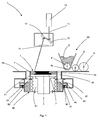
- FIG 1 schematically shows an embodiment of a machine 1 for the additive manufacturing of a part 20.
- the invention applies in reality to all types of additive manufacturing based on powder by sintering or by total melting of the grains of said powder by means of an energy beam such as electromagnetic radiation (for example a laser beam) or a particle beam (for example an electron beam).
- an energy beam such as electromagnetic radiation (for example a laser beam) or a particle beam (for example an electron beam).
- An energy source here a laser source 10 emits a laser beam 11 whose orientation is controlled by galvanometric mirrors 12.
- An optical lens 14 makes it possible to focus the beam 11 at the level of the working zone 4 in order to heat the upper layer of powder 2 in a specific pattern and thus selectively achieve the melting of the powder.
- the machine 1 also comprises a layering device 50 allowing the application of a new layer of powder on the working zone 4.
- the layering device 50 of the figure 1 comprises a feed hopper 5 and a distribution roller 6 of the powder 2 on the working zone 4.
- the feed hopper 5 comprises in its lower part a metering roller 8 having grooves 8a whose function is to transfer a precise amount or dose of powder 2 from the hopper 5 to the distribution roller 6.
- the layering device 50 further comprises a compacting roller 9.
- the final thickness of the powder layer is therefore the result of two successive operations .
- a first thickness is defined by the distribution roller 6, this thickness being then reduced and made even more homogeneous by the action of the compacting roller 9.
- the compaction roller 9 moves with the feed hopper 5 and the roller of Distribution 6.
- the feed hopper 5, the distribution roller 6 and the compaction roller 9 are carried by one or more carriages which are movable between the powder storage means (not shown) and the working zone 4.
- the working zone 4 is delimited within a fixed frame 40 of the machine 1, by a liner 41 inside which slides the production plate 7 driven in vertical translation by a jack 31, as indicated by the double arrow on the figure 1 .
- the liner 41 is integral with the frame 40, being mounted fixed or being made in one piece with the latter.
- the liner 41 has a cross section of circular, square or rectangular shape and is located within the frame 40 facing the zone of action of the laser source 10.
- the liner 41 has a central opening 43 for the passage of the plate 7 and lateral passages or openings 42.
- the lateral openings 42 are formed on the periphery of the liner 41, throughout its thickness, to allow the evacuation of excess powder 2 during layering.
- the plate 7 has a cross section having the same shape as that of the jacket 41 and dimensions close to them inside which it slides with a game j1.
- the plate 7 forms a support for the three-dimensional object that will be constructed.
- the liner 41 constitutes the frame of construction of the object and has a height at least equal to that of the three-dimensional object to be constructed to which is added the thickness of the plate 7.
- the cylinder 31 belongs to a translational movement device 30.
- the cylinder 31 may be of the pneumatic or electric hydraulic type. In a preferred embodiment of the invention, an electric cylinder is used, the displacement of the rod can be controlled very precisely.
- the translational movement device 30 comprises an outer casing integral with the chassis 40 of the machine and means for guiding in translation (not shown in the drawings) of the cylinder 31. The cylinder 31 is guided in translation inside the outer casing of the machine. device 30 between a high position and a low position, the head 32 of the cylinder 31 being intended to engage with the plate 7.
- the machine 1 comprises an interchangeable container 60 which is arranged between the liner 41 and the head 32 of the cylinder 31, when in the low position.
- the interchangeable container 60 is introduced under the jacket 41, in particular by sliding it on rails 44 belonging to the frame 40.
- the interchangeable container 60 comprises lateral support wings 64 which slide along the rails 44 to a stop of background that allows it a precise positioning next to the shirt 41. It is then fixed in this position by means of a fastening mechanism 80 with springs 81 allowing the upper edge of the container 60 to be pressed against the walls of the lower edge of the chassis 40.
- the interchangeable container 60 comprises an internal chamber 61 inside which can move in vertical translation the plate 7 under the action of the cylinder 31.
- the cross section of the inner chamber 61 has the same shape as that of the plate 7, the clearance between the outer periphery of the plate 7 and the walls of the inner chamber 61 being j2, with j2> j1.
- the inner chamber 61 is surrounded by a peripheral corridor 62 open at its upper part to communicate with the passages 42 of the chassis 40.
- the cross section of the peripheral corridor 62 is greater than that of the passages 42, the corridor being dimensioned so as to store all the amount of powder recovered during the different successive layers required for the manufacture of the object or part 20.
- the machine 1 does not comprise an interchangeable container, the plate 7 being slid inside the machine construction jacket, between a part upper case and a closed lower part around the cylinder head 32.
- the manufactured three-dimensional object is evacuated with the plate 7 by bringing the latter in the up position to remove it from the sleeve 41, in order to then be able to recover it at the upper surface of the chassis 40.
- the construction jacket is removable or belongs to a removable container.
- the manufacturing plate 7 slides freely inside the jacket 41, with no seal being provided on the periphery of the plate or between the latter and the jacket 41. Indeed Laboratory tests have shown that, for a clearance between the tray and the liner and a roughness of their predetermined facing surfaces, the powder particles do not block the interstice between the walls. internal of the construction shirt 41, but allow the sliding of the plate 7.
- the jack 31 is arranged inside a displacement device in translation, guiding means 90 being provided to ensure the translational guidance of the jack 31 within the device 30. More particularly according to the invention, the cylinder 31 is arranged inside a tubular column 39 inside which slides a tube 38, the cylinder of the jack being fixed to the column 39 and the rod to the tube 38, and translation guide means being provided between the tube 38 and the column 39.
- the jack is arranged inside a device which is ideally aligned on the axis of the plate 7, therefore under the center of gravity of the load to be supported, and allows to ensure a good transmission of the axial force of the cylinder 31.
- Such a cylinder arrangement ensures a support of the plate 7 on a support of large diameter, which allows it to withstand higher loads and reduce the boom, while allowing to have a compact construction of the translational movement device.
- Such a construction is suitable for use with a large plate, with a ratio between the dimensions (diameter) of the cylinder head 32 and those (diameter or width) of the plate 7 greater than 1: 2, preferably equal to about 3: 4.
- such a guide has a good vertical rigidity, which allows the device to collect forces transverse to the plate.
- the jack 31 is an electric jack, for example an electric lifting cylinder of the type MPAI from Rockwell Automation.
- a cylinder offers advantages of speed and positioning very accurate, as well as energy efficiency without the risk of contamination and cleaning of a hydraulic cylinder.
- the cylinder 31 is shown diagrammatically by a cylinder 33 inside which a rod 34 moves and is arranged in a vertical position inside a tubular column 39 mounted on the frame 40 of the machine 1.
- the cylinder 33 is secured by means of a lower ball 35 on a base plate 36 of the column 39.
- the rod 34 is mounted by means of an upper ball 37 on a top plate forming the cylinder head 32.
- the cylinder head 32 is fixed (by example using the screws) on the upper end face of an inner tube 38 by aligning the axis of the rod 34 along the axis of the tube 38.
- the inner tube 38 and column 39 have a generally cylindrical shape and are coaxial.
- the column 39 comprises three guide pads: two fixed guide shoes 91 and a movable guide shoe 91 'disposed on the circumference of the column 39 so that each guide shoe can come into contact with a flat portion 95 of the inner tube 38.
- each window 96 has a rectangular central through portion surrounded by a rectangular peripheral rim of thickness lower than in column 39.
- guide shoe 91 is an assembly composed of a liner 93 secured to a support plate 92 which is fixed on the column 39 with screws 94.
- the lining 93 is fixed on the support plate 92 by gluing or by mechanical fastening and is made of antifriction material having good sliding properties.
- antifriction material is a composite material with low friction coefficient, for example of the type D-Glide society Eternum ®.
- the movable guide shoe 91 comprises the same components as a fixed guide shoe 91, to which are added two spring washers (or "Belleville” washers) 97 ( Fig. 4 ) disposed between the screw 94 and the support plate 92. Such a shoe 91 'is then pressed against one of the flats 95 of the inner tube 38.
- This assembly solution with two fixed guide shoes 91 and a movable guide shoe 91 allows the guide assembly to function properly, avoiding a hyperstatic construction (with three fixed shoes), while allowing parallel sliding of the guide assemblies. pads on the flats of the tube and to absorb the geometric defects of the parts constituting the guide assembly, or even to compensate for the wear of the guide surfaces.
- the cylinder head 32 has an interface 32 'for supporting an intermediate plate 71 on which bears the support plate 7 of the object to be manufactured.
- the fixing between the intermediate plate 71 and the cylinder head 32 is by vacuum, a pipe 99 being connected to a vacuum pump (not shown) inside the column 39.
- a bellows 170 is disposed between the interface 32 'and the upper face of a flange 72 of the column 39.
- Fig. 7 illustrates the cylinder 31 in the fully deployed position and it is observed that the bellows 170 surrounds the inner tube 38 and seals between the cylinder head 32 and the column 39.
- the interface 32 ' comprises indexing means of the intermediate plate 71 relative to the jack 32, these indexing means comprising a cylindrical pin 73 constituting a complete centralizer and, diametrically opposed, a pin with prismatic head 74 constituting a centralizer cleared.
- the pin 73 blocks the translations Tx, Ty along the x and y axes and the pin 74 blocks the rotation Rz about the z axis.
- the other degrees of freedom are blocked by the support of the intermediate plate 71 on the interface 32 '.
- the intermediate plate is absent and the plate 7 comes into direct contact with the cylinder head 32 or with the interface 32 'which is provided with means for indexing and fixing the tray 7.
- the translational movement device 30 is mounted suspended within the frame 40 of the machine 1.
- the machine 1 comprises a support housing 200 fixedly mounted on the frame 40 thereof.
- the central part of the housing 200 comprises a tubular base 201 which ends at its upper part with a support ring 202 of the column 39.
- the column 39 has a ground distance of several tens mm, the frame 40 being fixed on the frame of the machine which takes, him, support to the ground by feet (not shown in the drawings).
- the flange 72 of the column 39 rests on the base 201 by means of a spherical articulation 204.
- the contact between the flange 72 and the support ring 202 is a contact sphere 203 whose center is located substantially in the center of the construction surface of the plate 7 when the latter is in the up position (it is understood at the same level as the upper face of the shirt 41). This allows an adjustment of the position of the translation device 30 along the axes Ox and Oy, as will be explained later.
- the column 39 is mounted by means of a precharging device 210 to the frame 40.
- the precharging device 210 comprises a square-shaped flange 211 having a central orifice 213, through which the lower portion of the column 39 passes to a shoulder 215 thereof, and four compression springs. 212 fixed at their lower end to the four corners of the flange 211. The upper end of each spring 212 is fixed on the lower part of the support 200.
- the fixing of the springs 212 is made on a few mm at their respective ends and the length ratio total / diameter of the spring 212 is chosen to be large enough that the springs 212 can provide a compression force in a vertical direction, without introducing parasitic lateral stresses.
- the force provided by the four springs 212 is about 600 daN.
- the precharging device instead uses compression springs articulated rods mounted on a ball and having elastic washers (or type "Belleville"). These assemblies make it possible to exert a vertical force on the column 39 and to keep it stationary while being pressed against the casing 200 (and thus on the frame 40) and to avoid the appearance of vibrations during operation.
- the displacement device 30 is adjustable by rotating about the x, y and z axes which are parallel to those of the machine reference system. As best seen in Figures 5 and 6 , the rotation about the z axis is done by turning the eccentric adjusting head 100 about its vertical axis.
- the x and y axis adjustments are made using the adjustment cylinders 216 and 217 ( Fig. 7 and 8 ) arranged one along the x-axis and the other along the y-axis, and whose head (it includes the end of the cylinder opposite to that of adjustment) is fixed on the column 39.
- Each adjustment cylinder 216 , 217 is mounted with a cylinder support 218, 219 to the housing 200 of the machine.
- An adjusting cylinder 216, 217 consists of a screw device and fine pitch nut, preloaded by an axial force provided by a spring (for example a compression spring or a package of elastic washers of "Belleville” type) for remove the gaps between the screw and the nut.
- a spring for example a compression spring or a package of elastic washers of "Belleville” type
- the head of the nut and that of the screw are spherical and cooperate with spherical bearing surfaces within the adjusting ram so as not to introduce parasitic forces on the column 39.
- the adjustment of the translational movement device 30 is done at the beginning of assembly operation of the assembly on the machine by mounting a plate 7 on the intermediate plate 71 which is secured to the cylinder head 32. A first around the z-axis is performed in order to orient the plate 7 with respect to the 41. Then, the plate 7 is brought to the upper position (at the level of the working zone 4) and a measurement is made of its flatness with respect to the machine's reference system. This measurement can be done using non-contact distance measuring sensors or by passing the lay-up roller and measuring the current absorbed by its actuating motor. The position of the plate 7 is then modified by actuating the adjustment cylinders 216, 217 so that it is well oriented relative to the sleeve 41. This adjustment is made when the machine is mounted, and then, if necessary, after checking with a reference plate.
- the machine 1 is first supplied with an interchangeable container 60 which contains a plate 7 situated in the lower part of the container 60, the bellows 70 being in the compressed state, under the plate 7.
- the interchangeable container 60 is arranged under the sleeve 41, by sliding it on the rails 44, to an abutment position.
- the container 60 is in the right position, it activates a fastening mechanism 80 of the latter relative to the frame 40.
- the control means of the machine allow the actuation of the cylinder 31. a translation movement upwards of its rod until its head 32 bears against the lower face of the intermediate plate 71 which supports the plate 7.
- the locking of the head 32 on the plate 7 is effected by actuating a device empty.
- the production plate 7 is pushed upwards by the cylinder head 32, controlled by the control means of the machine, through the inner chamber 61 and the building jacket 41 to the upper part thereof.
- the plate 7 is now ready to receive a layer of powder from the layering device 50.
- the layer of powder deposited is heated by the laser beam and solidified in precise points on its surface, according to the instructions received from a control unit of the machine 1.
- the plate descends being driven by the cylinder 31 so as to continue the manufacture by deposition and solidification of a new layer of powder.
- the cylinder head 32 descends until the plate 7 supporting the manufactured part is at the bottom of the interchangeable container 60.
- the cylinder head 32 further descends and is The attachment means 80 are then actuated to detach the interchangeable container 60 from the frame 40.
- the container 60 can now be removed from the frame 40 and transported (manually by an operator or preferably automatically using mechanical means, such as a chain conveyor, a robot arm, etc.) to another workstation that retrieves the part 20 and the plate 7 of the internal chamber 61, as well as the powder 2 present in the peripheral corridor 62.
- the powder used is preferably a metal or ceramic powder.
- the preferred particle size of the powder can vary from a few microns (for example 5 microns) to 300 or 400 microns.
- the translational guiding device can be arranged in an interchangeable container-free machine and having a manufacturing sleeve of the object which is crossed by the cylinder head and the plate.
- the liner may be absent, the container then comprising a frame for manufacturing the object and means for fixing the frame of the machine.
Landscapes
- Engineering & Computer Science (AREA)
- Chemical & Material Sciences (AREA)
- Materials Engineering (AREA)
- Manufacturing & Machinery (AREA)
- Physics & Mathematics (AREA)
- Mechanical Engineering (AREA)
- Optics & Photonics (AREA)
- Life Sciences & Earth Sciences (AREA)
- Sustainable Development (AREA)
- Plasma & Fusion (AREA)
- Powder Metallurgy (AREA)
Claims (11)
- Maschine (1) zur additiven Herstellung eines dreidimensionalen Objekts durch Sintern oder Schmelzen von Pulver (2) mittels eines auf eine Pulverschicht in einem Arbeitsbereich (4) wirkenden Energiestrahls (3), die eine Vorrichtung (30) zum vertikalen translatorischen Verschieben einer Trägerplatte (7) im Inneren eines Fertigungsraums (41) aufweist, der an dem Gestell (40) der Maschine befestigt ist, wobei die Vorrichtung Folgendes aufweist:- eine Säule (39), die an dem Gestell (40) befestigt ist, in deren Inneren- ein Zylinder (31) angeordnet ist, der einen einstückig mit der Säule ausgebildeten Körper und eine mit der Platte (7) verbundene, bewegliche Stange aufweist- Mittel (90) zum Führen der beweglichen Stange des Zylinders (31),dadurch gekennzeichnet, dass die Führungsmittel (90) prismatische Führungselemente an der Säule (39) und an einem Rohr (38), das koaxial zu ihr angeordnet ist und sich mit der beweglichen Stange des Zylinders (31) verschiebt, aufweisen.
- Maschine nach Anspruch 1, dadurch gekennzeichnet, dass das Rohr (38) im Inneren der Säule (39) angeordnet ist.
- Maschine nach einem der Ansprüche 1 oder 2, dadurch gekennzeichnet, dass die Säule (39) mehrere Führungsleisten (91, 91') aufweist, die gleichmäßig über ihren Innenumfang verteilt sind und dazu bestimmt sind, mit den Abflachungen (95) in Kontakt zu kommen, die an der Außenseite des Rohrs (38) vorgesehen sind.
- Maschine nach Anspruch 3, dadurch gekennzeichnet, dass sie zwei feststehende Führungsleisten (91) und eine bewegliche Führungsleiste (91') aufweist.
- Maschine nach einem der vorhergehenden Ansprüche, dadurch gekennzeichnet, dass sie einen dichten Balg aufweist, der zwischen der Säule (39) und dem Rohr (38) vorgesehen ist.
- Maschine nach einem der vorhergehenden Ansprüche, dadurch gekennzeichnet, dass die Säule mittels einer Vorspannvorrichtung (210) an dem Gestell (40) befestigt ist.
- Maschine nach einem der vorhergehenden Ansprüche, dadurch gekennzeichnet, dass die Säule (39) mittels eines Kugelgelenks (204) relativ zu dem Gestell (40) befestigt ist.
- Maschine nach Anspruch 7, dadurch gekennzeichnet, dass sich der Mittelpunkt der Kontaktkugel (203) des Kugelgelenks (204) auf der Konstruktionsfläche der Trägerplatte befindet.
- Maschine nach einem der vorhergehenden Ansprüche, dadurch gekennzeichnet, dass sie Mittel zum Einstellen der Position der Säule (39) relativ zu dem Gestell (40) aufweist.
- Maschine nach Anspruch 9, dadurch gekennzeichnet, dass die Einstellmittel geeignet sind, die Position der Säule (39) um das Kugelgelenk (204) herum einzustellen.
- Maschine nach einem der vorhergehenden Ansprüche, dadurch gekennzeichnet, dass sich die Platte (7) im Inneren eines Raums (41), der zu dem Gestell (40) der Maschine gehört, und im Inneren eines Wechselbehälters (60), der unter dem Raum (41) vorgesehen ist, verschiebt.
Applications Claiming Priority (2)
| Application Number | Priority Date | Filing Date | Title |
|---|---|---|---|
| FR1257420A FR2994114B1 (fr) | 2012-07-31 | 2012-07-31 | Machine pour la fabrication additive a base de poudre |
| PCT/EP2013/066131 WO2014020086A2 (fr) | 2012-07-31 | 2013-07-31 | Machine pour la fabrication additive à base de poudre |
Publications (2)
| Publication Number | Publication Date |
|---|---|
| EP2879820A2 EP2879820A2 (de) | 2015-06-10 |
| EP2879820B1 true EP2879820B1 (de) | 2016-09-14 |
Family
ID=47754599
Family Applications (1)
| Application Number | Title | Priority Date | Filing Date |
|---|---|---|---|
| EP13744538.3A Active EP2879820B1 (de) | 2012-07-31 | 2013-07-31 | Maschine zur herstellung eines pulverförmigen zusatzstoffs |
Country Status (3)
| Country | Link |
|---|---|
| EP (1) | EP2879820B1 (de) |
| FR (1) | FR2994114B1 (de) |
| WO (1) | WO2014020086A2 (de) |
Families Citing this family (6)
| Publication number | Priority date | Publication date | Assignee | Title |
|---|---|---|---|---|
| DE102015211538A1 (de) * | 2015-06-23 | 2016-12-29 | Trumpf Laser- Und Systemtechnik Gmbh | Bauzylinder-Anordnung für eine Maschine zur schichtweisen Fertigung dreidimensionaler Objekte |
| CN105538725B (zh) * | 2016-02-17 | 2018-12-11 | 李全贵 | 激光成型机 |
| CN109311233A (zh) | 2016-05-12 | 2019-02-05 | 惠普发展公司,有限责任合伙企业 | 增材制造运输装置 |
| IT201600069590A1 (it) * | 2016-07-05 | 2018-01-05 | 3D New Tech S R L | Pistone per un'apparecchiatura per additive manufacturing |
| EP3446858A1 (de) * | 2017-08-25 | 2019-02-27 | CL Schutzrechtsverwaltungs GmbH | Vorrichtung zur generativen fertigung von dreidimensionalen objekten |
| WO2019187111A1 (ja) * | 2018-03-30 | 2019-10-03 | シーメット株式会社 | 3次元積層造形装置および3次元積層造形装置の製造方法 |
Family Cites Families (8)
| Publication number | Priority date | Publication date | Assignee | Title |
|---|---|---|---|---|
| US5387380A (en) * | 1989-12-08 | 1995-02-07 | Massachusetts Institute Of Technology | Three-dimensional printing techniques |
| IT1290210B1 (it) * | 1997-01-29 | 1998-10-22 | Pirelli | Metodo per la produzione di pneumatici,per la realizzazione di stampi di vulcanizzazione per detti pneumatici,pneumatici e stampi cosi' |
| DE19846478C5 (de) | 1998-10-09 | 2004-10-14 | Eos Gmbh Electro Optical Systems | Laser-Sintermaschine |
| DE19939616C5 (de) * | 1999-08-20 | 2008-05-21 | Eos Gmbh Electro Optical Systems | Vorrichtung zur generativen Herstellung eines dreidimensionalen Objektes |
| SE521124C2 (sv) * | 2000-04-27 | 2003-09-30 | Arcam Ab | Anordning samt metod för framställande av en tredimensionell produkt |
| DE102004057865B4 (de) * | 2004-11-30 | 2008-01-10 | Cl Schutzrechtsverwaltungs Gmbh | Vorrichtung zum Herstellen eines dreidimensionalen Objektes |
| DE102010006939A1 (de) * | 2010-02-04 | 2011-08-04 | Voxeljet Technology GmbH, 86167 | Vorrichtung zum Herstellen dreidimensionaler Modelle |
| DE102010011059A1 (de) * | 2010-03-11 | 2011-09-15 | Global Beam Technologies Ag | Verfahren und Vorrichtung zur Herstellung eines Bauteils |
-
2012
- 2012-07-31 FR FR1257420A patent/FR2994114B1/fr not_active Expired - Fee Related
-
2013
- 2013-07-31 WO PCT/EP2013/066131 patent/WO2014020086A2/fr not_active Ceased
- 2013-07-31 EP EP13744538.3A patent/EP2879820B1/de active Active
Also Published As
| Publication number | Publication date |
|---|---|
| WO2014020086A3 (fr) | 2014-04-10 |
| FR2994114A1 (fr) | 2014-02-07 |
| EP2879820A2 (de) | 2015-06-10 |
| FR2994114B1 (fr) | 2014-09-05 |
| WO2014020086A2 (fr) | 2014-02-06 |
Similar Documents
| Publication | Publication Date | Title |
|---|---|---|
| EP2879820B1 (de) | Maschine zur herstellung eines pulverförmigen zusatzstoffs | |
| EP2879819B1 (de) | Maschine und verfahren zur herstellung eines auf pulver basierenden additivs | |
| EP3215349B1 (de) | Vorrichtung und verfahren zur pulverbasierten generativen herstellung | |
| EP0334912B1 (de) | Prozedur und gleitbare unterstützung für ein profilmepinstrument | |
| EP3160843B1 (de) | Radantriebssystem, insbesondere für ein flugzeug | |
| EP2874827B1 (de) | Achse und fahrzeug mit mindestens einer solchen achse | |
| EP2493680B1 (de) | Anlage zur herstellung eines festprodukts mithilfe eines oder mehrerer pulvermaterialien | |
| CA2853381A1 (fr) | Installation de fabrication de pieces par fusion selective de poudre | |
| EP4049936B1 (de) | System mit einem beweglichen schlitten und verfahren zur anwendung eines solchen systems mit beweglichem schlitten | |
| EP0365447B1 (de) | Verfahren und Vorrichtung zum Zusammenpressen und Steuern der Zusammenpressung von pulverförmigen Materialien und Presse zur Anwendung in diesem Verfahren | |
| FR2638238A1 (fr) | Detecteur pour le radiocarottage avec une interface optique de decouplage | |
| WO2010125112A1 (fr) | Systeme mecanique de guidage automatique d' une ou plusieurs torches d' une unite de soudage avec trois axes de pivotement pour la (les ) torche ( s ) | |
| WO2020239553A1 (fr) | Machine de fabrication additive a distribution de poudre par tamisage | |
| EP3931064B1 (de) | System zur immobilisierung eines medizinischen roboters | |
| EP3894186B1 (de) | Vorrichtung zur generativen fertigung mit einem kompakten aktuator | |
| WO2020099732A1 (fr) | Plateforme adaptative amovible de fabrication additive pour un équipement de fabrication additive métallique par fusion laser | |
| FR2735409A1 (fr) | Dispositif pour positionner la tige pilote d'une broche d'usinage | |
| FR2970198A1 (fr) | Machine de manipulation d'outillage | |
| FR3017820A1 (fr) | Dispositif de pose de fibres | |
| FR3020307B1 (fr) | Dispositif de pose de fibres | |
| EP0862696A1 (de) | Dreiachsen-positionsantriebe und verfahren zu deren einstellung | |
| WO2009007572A1 (fr) | Dispositif rotatif de transfert et d'indexation d'objets metalliques, comportant des moyens d'entrainement sans contact | |
| CA1135488A (fr) | Procede de positionnement precis d'un ou de plusieurs outils sur le plan de coupe d'une structure tubulaire ainsi que dispositif de mise en oeuvre du procede | |
| FR3015020A1 (fr) | Dispositif et procede de positionnement d'une piece a mesurer | |
| FR3011816A1 (fr) | Train d'atterrissage a balancier et giravion |
Legal Events
| Date | Code | Title | Description |
|---|---|---|---|
| PUAI | Public reference made under article 153(3) epc to a published international application that has entered the european phase |
Free format text: ORIGINAL CODE: 0009012 |
|
| 17P | Request for examination filed |
Effective date: 20150302 |
|
| AK | Designated contracting states |
Kind code of ref document: A2 Designated state(s): AL AT BE BG CH CY CZ DE DK EE ES FI FR GB GR HR HU IE IS IT LI LT LU LV MC MK MT NL NO PL PT RO RS SE SI SK SM TR |
|
| AX | Request for extension of the european patent |
Extension state: BA ME |
|
| DAX | Request for extension of the european patent (deleted) | ||
| GRAP | Despatch of communication of intention to grant a patent |
Free format text: ORIGINAL CODE: EPIDOSNIGR1 |
|
| INTG | Intention to grant announced |
Effective date: 20160330 |
|
| RIN1 | Information on inventor provided before grant (corrected) |
Inventor name: TORRES-CATELLANO, MIGUEL |
|
| GRAS | Grant fee paid |
Free format text: ORIGINAL CODE: EPIDOSNIGR3 |
|
| GRAA | (expected) grant |
Free format text: ORIGINAL CODE: 0009210 |
|
| AK | Designated contracting states |
Kind code of ref document: B1 Designated state(s): AL AT BE BG CH CY CZ DE DK EE ES FI FR GB GR HR HU IE IS IT LI LT LU LV MC MK MT NL NO PL PT RO RS SE SI SK SM TR |
|
| REG | Reference to a national code |
Ref country code: GB Ref legal event code: FG4D Free format text: NOT ENGLISH |
|
| REG | Reference to a national code |
Ref country code: CH Ref legal event code: EP |
|
| REG | Reference to a national code |
Ref country code: IE Ref legal event code: FG4D Free format text: LANGUAGE OF EP DOCUMENT: FRENCH |
|
| REG | Reference to a national code |
Ref country code: AT Ref legal event code: REF Ref document number: 828373 Country of ref document: AT Kind code of ref document: T Effective date: 20161015 |
|
| REG | Reference to a national code |
Ref country code: DE Ref legal event code: R096 Ref document number: 602013011618 Country of ref document: DE |
|
| REG | Reference to a national code |
Ref country code: LT Ref legal event code: MG4D |
|
| REG | Reference to a national code |
Ref country code: NL Ref legal event code: MP Effective date: 20160914 |
|
| PG25 | Lapsed in a contracting state [announced via postgrant information from national office to epo] |
Ref country code: HR Free format text: LAPSE BECAUSE OF FAILURE TO SUBMIT A TRANSLATION OF THE DESCRIPTION OR TO PAY THE FEE WITHIN THE PRESCRIBED TIME-LIMIT Effective date: 20160914 Ref country code: LT Free format text: LAPSE BECAUSE OF FAILURE TO SUBMIT A TRANSLATION OF THE DESCRIPTION OR TO PAY THE FEE WITHIN THE PRESCRIBED TIME-LIMIT Effective date: 20160914 Ref country code: RS Free format text: LAPSE BECAUSE OF FAILURE TO SUBMIT A TRANSLATION OF THE DESCRIPTION OR TO PAY THE FEE WITHIN THE PRESCRIBED TIME-LIMIT Effective date: 20160914 Ref country code: NO Free format text: LAPSE BECAUSE OF FAILURE TO SUBMIT A TRANSLATION OF THE DESCRIPTION OR TO PAY THE FEE WITHIN THE PRESCRIBED TIME-LIMIT Effective date: 20161214 Ref country code: FI Free format text: LAPSE BECAUSE OF FAILURE TO SUBMIT A TRANSLATION OF THE DESCRIPTION OR TO PAY THE FEE WITHIN THE PRESCRIBED TIME-LIMIT Effective date: 20160914 |
|
| REG | Reference to a national code |
Ref country code: AT Ref legal event code: MK05 Ref document number: 828373 Country of ref document: AT Kind code of ref document: T Effective date: 20160914 |
|
| PG25 | Lapsed in a contracting state [announced via postgrant information from national office to epo] |
Ref country code: NL Free format text: LAPSE BECAUSE OF FAILURE TO SUBMIT A TRANSLATION OF THE DESCRIPTION OR TO PAY THE FEE WITHIN THE PRESCRIBED TIME-LIMIT Effective date: 20160914 Ref country code: LV Free format text: LAPSE BECAUSE OF FAILURE TO SUBMIT A TRANSLATION OF THE DESCRIPTION OR TO PAY THE FEE WITHIN THE PRESCRIBED TIME-LIMIT Effective date: 20160914 Ref country code: SE Free format text: LAPSE BECAUSE OF FAILURE TO SUBMIT A TRANSLATION OF THE DESCRIPTION OR TO PAY THE FEE WITHIN THE PRESCRIBED TIME-LIMIT Effective date: 20160914 Ref country code: GR Free format text: LAPSE BECAUSE OF FAILURE TO SUBMIT A TRANSLATION OF THE DESCRIPTION OR TO PAY THE FEE WITHIN THE PRESCRIBED TIME-LIMIT Effective date: 20161215 |
|
| PG25 | Lapsed in a contracting state [announced via postgrant information from national office to epo] |
Ref country code: RO Free format text: LAPSE BECAUSE OF FAILURE TO SUBMIT A TRANSLATION OF THE DESCRIPTION OR TO PAY THE FEE WITHIN THE PRESCRIBED TIME-LIMIT Effective date: 20160914 Ref country code: EE Free format text: LAPSE BECAUSE OF FAILURE TO SUBMIT A TRANSLATION OF THE DESCRIPTION OR TO PAY THE FEE WITHIN THE PRESCRIBED TIME-LIMIT Effective date: 20160914 |
|
| PG25 | Lapsed in a contracting state [announced via postgrant information from national office to epo] |
Ref country code: AT Free format text: LAPSE BECAUSE OF FAILURE TO SUBMIT A TRANSLATION OF THE DESCRIPTION OR TO PAY THE FEE WITHIN THE PRESCRIBED TIME-LIMIT Effective date: 20160914 Ref country code: CZ Free format text: LAPSE BECAUSE OF FAILURE TO SUBMIT A TRANSLATION OF THE DESCRIPTION OR TO PAY THE FEE WITHIN THE PRESCRIBED TIME-LIMIT Effective date: 20160914 Ref country code: PT Free format text: LAPSE BECAUSE OF FAILURE TO SUBMIT A TRANSLATION OF THE DESCRIPTION OR TO PAY THE FEE WITHIN THE PRESCRIBED TIME-LIMIT Effective date: 20170116 Ref country code: SM Free format text: LAPSE BECAUSE OF FAILURE TO SUBMIT A TRANSLATION OF THE DESCRIPTION OR TO PAY THE FEE WITHIN THE PRESCRIBED TIME-LIMIT Effective date: 20160914 Ref country code: SK Free format text: LAPSE BECAUSE OF FAILURE TO SUBMIT A TRANSLATION OF THE DESCRIPTION OR TO PAY THE FEE WITHIN THE PRESCRIBED TIME-LIMIT Effective date: 20160914 Ref country code: IS Free format text: LAPSE BECAUSE OF FAILURE TO SUBMIT A TRANSLATION OF THE DESCRIPTION OR TO PAY THE FEE WITHIN THE PRESCRIBED TIME-LIMIT Effective date: 20170114 Ref country code: BG Free format text: LAPSE BECAUSE OF FAILURE TO SUBMIT A TRANSLATION OF THE DESCRIPTION OR TO PAY THE FEE WITHIN THE PRESCRIBED TIME-LIMIT Effective date: 20161214 Ref country code: ES Free format text: LAPSE BECAUSE OF FAILURE TO SUBMIT A TRANSLATION OF THE DESCRIPTION OR TO PAY THE FEE WITHIN THE PRESCRIBED TIME-LIMIT Effective date: 20160914 Ref country code: PL Free format text: LAPSE BECAUSE OF FAILURE TO SUBMIT A TRANSLATION OF THE DESCRIPTION OR TO PAY THE FEE WITHIN THE PRESCRIBED TIME-LIMIT Effective date: 20160914 |
|
| REG | Reference to a national code |
Ref country code: DE Ref legal event code: R097 Ref document number: 602013011618 Country of ref document: DE |
|
| PG25 | Lapsed in a contracting state [announced via postgrant information from national office to epo] |
Ref country code: IT Free format text: LAPSE BECAUSE OF FAILURE TO SUBMIT A TRANSLATION OF THE DESCRIPTION OR TO PAY THE FEE WITHIN THE PRESCRIBED TIME-LIMIT Effective date: 20160914 |
|
| PLBE | No opposition filed within time limit |
Free format text: ORIGINAL CODE: 0009261 |
|
| STAA | Information on the status of an ep patent application or granted ep patent |
Free format text: STATUS: NO OPPOSITION FILED WITHIN TIME LIMIT |
|
| REG | Reference to a national code |
Ref country code: FR Ref legal event code: PLFP Year of fee payment: 5 |
|
| PG25 | Lapsed in a contracting state [announced via postgrant information from national office to epo] |
Ref country code: DK Free format text: LAPSE BECAUSE OF FAILURE TO SUBMIT A TRANSLATION OF THE DESCRIPTION OR TO PAY THE FEE WITHIN THE PRESCRIBED TIME-LIMIT Effective date: 20160914 |
|
| 26N | No opposition filed |
Effective date: 20170615 |
|
| PG25 | Lapsed in a contracting state [announced via postgrant information from national office to epo] |
Ref country code: SI Free format text: LAPSE BECAUSE OF FAILURE TO SUBMIT A TRANSLATION OF THE DESCRIPTION OR TO PAY THE FEE WITHIN THE PRESCRIBED TIME-LIMIT Effective date: 20160914 |
|
| REG | Reference to a national code |
Ref country code: CH Ref legal event code: PL |
|
| GBPC | Gb: european patent ceased through non-payment of renewal fee |
Effective date: 20170731 |
|
| PG25 | Lapsed in a contracting state [announced via postgrant information from national office to epo] |
Ref country code: GB Free format text: LAPSE BECAUSE OF NON-PAYMENT OF DUE FEES Effective date: 20170731 Ref country code: LI Free format text: LAPSE BECAUSE OF NON-PAYMENT OF DUE FEES Effective date: 20170731 Ref country code: CH Free format text: LAPSE BECAUSE OF NON-PAYMENT OF DUE FEES Effective date: 20170731 |
|
| REG | Reference to a national code |
Ref country code: IE Ref legal event code: MM4A |
|
| REG | Reference to a national code |
Ref country code: BE Ref legal event code: MM Effective date: 20170731 |
|
| PG25 | Lapsed in a contracting state [announced via postgrant information from national office to epo] |
Ref country code: LU Free format text: LAPSE BECAUSE OF NON-PAYMENT OF DUE FEES Effective date: 20170731 |
|
| REG | Reference to a national code |
Ref country code: FR Ref legal event code: PLFP Year of fee payment: 6 |
|
| PG25 | Lapsed in a contracting state [announced via postgrant information from national office to epo] |
Ref country code: IE Free format text: LAPSE BECAUSE OF NON-PAYMENT OF DUE FEES Effective date: 20170731 |
|
| PG25 | Lapsed in a contracting state [announced via postgrant information from national office to epo] |
Ref country code: BE Free format text: LAPSE BECAUSE OF NON-PAYMENT OF DUE FEES Effective date: 20170731 |
|
| PG25 | Lapsed in a contracting state [announced via postgrant information from national office to epo] |
Ref country code: MT Free format text: LAPSE BECAUSE OF FAILURE TO SUBMIT A TRANSLATION OF THE DESCRIPTION OR TO PAY THE FEE WITHIN THE PRESCRIBED TIME-LIMIT Effective date: 20160914 |
|
| PG25 | Lapsed in a contracting state [announced via postgrant information from national office to epo] |
Ref country code: AL Free format text: LAPSE BECAUSE OF FAILURE TO SUBMIT A TRANSLATION OF THE DESCRIPTION OR TO PAY THE FEE WITHIN THE PRESCRIBED TIME-LIMIT Effective date: 20160914 |
|
| PG25 | Lapsed in a contracting state [announced via postgrant information from national office to epo] |
Ref country code: HU Free format text: LAPSE BECAUSE OF FAILURE TO SUBMIT A TRANSLATION OF THE DESCRIPTION OR TO PAY THE FEE WITHIN THE PRESCRIBED TIME-LIMIT; INVALID AB INITIO Effective date: 20130731 Ref country code: MC Free format text: LAPSE BECAUSE OF FAILURE TO SUBMIT A TRANSLATION OF THE DESCRIPTION OR TO PAY THE FEE WITHIN THE PRESCRIBED TIME-LIMIT Effective date: 20160914 |
|
| PG25 | Lapsed in a contracting state [announced via postgrant information from national office to epo] |
Ref country code: CY Free format text: LAPSE BECAUSE OF FAILURE TO SUBMIT A TRANSLATION OF THE DESCRIPTION OR TO PAY THE FEE WITHIN THE PRESCRIBED TIME-LIMIT Effective date: 20160914 |
|
| PG25 | Lapsed in a contracting state [announced via postgrant information from national office to epo] |
Ref country code: MK Free format text: LAPSE BECAUSE OF FAILURE TO SUBMIT A TRANSLATION OF THE DESCRIPTION OR TO PAY THE FEE WITHIN THE PRESCRIBED TIME-LIMIT Effective date: 20160914 |
|
| PG25 | Lapsed in a contracting state [announced via postgrant information from national office to epo] |
Ref country code: TR Free format text: LAPSE BECAUSE OF FAILURE TO SUBMIT A TRANSLATION OF THE DESCRIPTION OR TO PAY THE FEE WITHIN THE PRESCRIBED TIME-LIMIT Effective date: 20160914 |
|
| REG | Reference to a national code |
Ref country code: DE Ref legal event code: R081 Ref document number: 602013011618 Country of ref document: DE Owner name: COMPAGNIE GENERALE DES ETABLISSEMENTS MICHELIN, FR Free format text: FORMER OWNERS: COMPAGNIE GENERALE DES ETABLISSEMENTS MICHELIN, CLERMONT-FERRAND, FR; MICHELIN RECHERCHE ET TECHNIQUE S.A., GRANGES-PACCOT, CH |
|
| PGFP | Annual fee paid to national office [announced via postgrant information from national office to epo] |
Ref country code: FR Payment date: 20250620 Year of fee payment: 13 |
|
| PGFP | Annual fee paid to national office [announced via postgrant information from national office to epo] |
Ref country code: DE Payment date: 20250620 Year of fee payment: 13 |