EP2879565B1 - Fibrescope for optical imaging of radiopharmaceuticals - Google Patents
Fibrescope for optical imaging of radiopharmaceuticals Download PDFInfo
- Publication number
- EP2879565B1 EP2879565B1 EP13745898.0A EP13745898A EP2879565B1 EP 2879565 B1 EP2879565 B1 EP 2879565B1 EP 13745898 A EP13745898 A EP 13745898A EP 2879565 B1 EP2879565 B1 EP 2879565B1
- Authority
- EP
- European Patent Office
- Prior art keywords
- shroud
- light
- fibrescope
- image
- cerenkov
- Prior art date
- Legal status (The legal status is an assumption and is not a legal conclusion. Google has not performed a legal analysis and makes no representation as to the accuracy of the status listed.)
- Not-in-force
Links
- 229940121896 radiopharmaceutical Drugs 0.000 title claims description 25
- 239000012217 radiopharmaceutical Substances 0.000 title claims description 25
- 230000002799 radiopharmaceutical effect Effects 0.000 title claims description 25
- 238000012634 optical imaging Methods 0.000 title claims description 15
- 238000003384 imaging method Methods 0.000 claims description 105
- 238000000034 method Methods 0.000 claims description 36
- 238000005286 illumination Methods 0.000 claims description 31
- 230000003287 optical effect Effects 0.000 claims description 29
- 238000004020 luminiscence type Methods 0.000 claims description 27
- 230000005855 radiation Effects 0.000 claims description 12
- 238000007789 sealing Methods 0.000 claims description 8
- 239000000835 fiber Substances 0.000 claims description 5
- 230000001360 synchronised effect Effects 0.000 claims description 5
- 230000000903 blocking effect Effects 0.000 claims description 4
- 239000002245 particle Substances 0.000 description 16
- 239000000463 material Substances 0.000 description 13
- 239000011521 glass Substances 0.000 description 10
- 230000000694 effects Effects 0.000 description 9
- 238000002474 experimental method Methods 0.000 description 9
- 238000001228 spectrum Methods 0.000 description 8
- 238000005259 measurement Methods 0.000 description 7
- 238000012545 processing Methods 0.000 description 7
- 230000003595 spectral effect Effects 0.000 description 7
- 229920001971 elastomer Polymers 0.000 description 6
- 230000002159 abnormal effect Effects 0.000 description 5
- 230000004907 flux Effects 0.000 description 5
- 229910052751 metal Inorganic materials 0.000 description 5
- 239000002184 metal Substances 0.000 description 5
- 230000007935 neutral effect Effects 0.000 description 5
- 229920001296 polysiloxane Polymers 0.000 description 5
- 230000008901 benefit Effects 0.000 description 4
- 230000010354 integration Effects 0.000 description 4
- ZOXJGFHDIHLPTG-UHFFFAOYSA-N Boron Chemical compound [B] ZOXJGFHDIHLPTG-UHFFFAOYSA-N 0.000 description 3
- 230000003321 amplification Effects 0.000 description 3
- 238000013459 approach Methods 0.000 description 3
- 229910052796 boron Inorganic materials 0.000 description 3
- 229920001903 high density polyethylene Polymers 0.000 description 3
- 239000004700 high-density polyethylene Substances 0.000 description 3
- 238000003199 nucleic acid amplification method Methods 0.000 description 3
- 230000004044 response Effects 0.000 description 3
- 230000035945 sensitivity Effects 0.000 description 3
- 230000009286 beneficial effect Effects 0.000 description 2
- 238000001444 catalytic combustion detection Methods 0.000 description 2
- 230000005466 cherenkov radiation Effects 0.000 description 2
- 230000008878 coupling Effects 0.000 description 2
- 238000010168 coupling process Methods 0.000 description 2
- 238000005859 coupling reaction Methods 0.000 description 2
- 238000001839 endoscopy Methods 0.000 description 2
- 239000004744 fabric Substances 0.000 description 2
- 230000000977 initiatory effect Effects 0.000 description 2
- 238000012423 maintenance Methods 0.000 description 2
- 230000000873 masking effect Effects 0.000 description 2
- 230000035515 penetration Effects 0.000 description 2
- 229920003023 plastic Polymers 0.000 description 2
- 239000004033 plastic Substances 0.000 description 2
- 229920001084 poly(chloroprene) Polymers 0.000 description 2
- 238000003908 quality control method Methods 0.000 description 2
- 238000012360 testing method Methods 0.000 description 2
- 230000007704 transition Effects 0.000 description 2
- 238000002834 transmittance Methods 0.000 description 2
- 238000001429 visible spectrum Methods 0.000 description 2
- ZCXUVYAZINUVJD-AHXZWLDOSA-N 2-deoxy-2-((18)F)fluoro-alpha-D-glucose Chemical compound OC[C@H]1O[C@H](O)[C@H]([18F])[C@@H](O)[C@@H]1O ZCXUVYAZINUVJD-AHXZWLDOSA-N 0.000 description 1
- IAYPIBMASNFSPL-UHFFFAOYSA-N Ethylene oxide Chemical compound C1CO1 IAYPIBMASNFSPL-UHFFFAOYSA-N 0.000 description 1
- 206010028980 Neoplasm Diseases 0.000 description 1
- 208000003443 Unconsciousness Diseases 0.000 description 1
- QCWXUUIWCKQGHC-UHFFFAOYSA-N Zirconium Chemical compound [Zr] QCWXUUIWCKQGHC-UHFFFAOYSA-N 0.000 description 1
- 230000002238 attenuated effect Effects 0.000 description 1
- 230000005540 biological transmission Effects 0.000 description 1
- 239000002775 capsule Substances 0.000 description 1
- 230000008859 change Effects 0.000 description 1
- 230000001427 coherent effect Effects 0.000 description 1
- 239000002131 composite material Substances 0.000 description 1
- 238000012790 confirmation Methods 0.000 description 1
- 238000010276 construction Methods 0.000 description 1
- 238000001816 cooling Methods 0.000 description 1
- 238000002059 diagnostic imaging Methods 0.000 description 1
- 229940127043 diagnostic radiopharmaceutical Drugs 0.000 description 1
- 239000000806 elastomer Substances 0.000 description 1
- 239000011152 fibreglass Substances 0.000 description 1
- 244000144992 flock Species 0.000 description 1
- YCKRFDGAMUMZLT-BJUDXGSMSA-N fluorine-18 atom Chemical compound [18F] YCKRFDGAMUMZLT-BJUDXGSMSA-N 0.000 description 1
- 239000006260 foam Substances 0.000 description 1
- 239000011888 foil Substances 0.000 description 1
- 230000006872 improvement Effects 0.000 description 1
- 238000000338 in vitro Methods 0.000 description 1
- 238000011065 in-situ storage Methods 0.000 description 1
- 230000036512 infertility Effects 0.000 description 1
- 238000002347 injection Methods 0.000 description 1
- 239000007924 injection Substances 0.000 description 1
- 230000003993 interaction Effects 0.000 description 1
- 239000005355 lead glass Substances 0.000 description 1
- 239000007788 liquid Substances 0.000 description 1
- 239000004973 liquid crystal related substance Substances 0.000 description 1
- 239000011104 metalized film Substances 0.000 description 1
- 238000012986 modification Methods 0.000 description 1
- 230000004048 modification Effects 0.000 description 1
- 238000012633 nuclear imaging Methods 0.000 description 1
- 238000009206 nuclear medicine Methods 0.000 description 1
- 238000012856 packing Methods 0.000 description 1
- 229920003229 poly(methyl methacrylate) Polymers 0.000 description 1
- 229920000642 polymer Polymers 0.000 description 1
- 239000004926 polymethyl methacrylate Substances 0.000 description 1
- 229920002635 polyurethane Polymers 0.000 description 1
- 239000004814 polyurethane Substances 0.000 description 1
- 238000003825 pressing Methods 0.000 description 1
- 230000005258 radioactive decay Effects 0.000 description 1
- 230000009467 reduction Effects 0.000 description 1
- 238000011160 research Methods 0.000 description 1
- 238000002432 robotic surgery Methods 0.000 description 1
- 238000009416 shuttering Methods 0.000 description 1
- 238000001356 surgical procedure Methods 0.000 description 1
- SITVSCPRJNYAGV-UHFFFAOYSA-L tellurite Chemical compound [O-][Te]([O-])=O SITVSCPRJNYAGV-UHFFFAOYSA-L 0.000 description 1
- 238000003325 tomography Methods 0.000 description 1
- 229910052726 zirconium Inorganic materials 0.000 description 1
Images


Classifications
-
- G—PHYSICS
- G01—MEASURING; TESTING
- G01N—INVESTIGATING OR ANALYSING MATERIALS BY DETERMINING THEIR CHEMICAL OR PHYSICAL PROPERTIES
- G01N23/00—Investigating or analysing materials by the use of wave or particle radiation, e.g. X-rays or neutrons, not covered by groups G01N3/00 – G01N17/00, G01N21/00 or G01N22/00
- G01N23/02—Investigating or analysing materials by the use of wave or particle radiation, e.g. X-rays or neutrons, not covered by groups G01N3/00 – G01N17/00, G01N21/00 or G01N22/00 by transmitting the radiation through the material
- G01N23/04—Investigating or analysing materials by the use of wave or particle radiation, e.g. X-rays or neutrons, not covered by groups G01N3/00 – G01N17/00, G01N21/00 or G01N22/00 by transmitting the radiation through the material and forming images of the material
- G01N23/043—Investigating or analysing materials by the use of wave or particle radiation, e.g. X-rays or neutrons, not covered by groups G01N3/00 – G01N17/00, G01N21/00 or G01N22/00 by transmitting the radiation through the material and forming images of the material using fluoroscopic examination, with visual observation or video transmission of fluoroscopic images
-
- A—HUMAN NECESSITIES
- A61—MEDICAL OR VETERINARY SCIENCE; HYGIENE
- A61B—DIAGNOSIS; SURGERY; IDENTIFICATION
- A61B1/00—Instruments for performing medical examinations of the interior of cavities or tubes of the body by visual or photographical inspection, e.g. endoscopes; Illuminating arrangements therefor
- A61B1/00002—Operational features of endoscopes
- A61B1/00004—Operational features of endoscopes characterised by electronic signal processing
- A61B1/00009—Operational features of endoscopes characterised by electronic signal processing of image signals during a use of endoscope
- A61B1/000095—Operational features of endoscopes characterised by electronic signal processing of image signals during a use of endoscope for image enhancement
-
- A—HUMAN NECESSITIES
- A61—MEDICAL OR VETERINARY SCIENCE; HYGIENE
- A61B—DIAGNOSIS; SURGERY; IDENTIFICATION
- A61B1/00—Instruments for performing medical examinations of the interior of cavities or tubes of the body by visual or photographical inspection, e.g. endoscopes; Illuminating arrangements therefor
- A61B1/00002—Operational features of endoscopes
- A61B1/00043—Operational features of endoscopes provided with output arrangements
- A61B1/00045—Display arrangement
- A61B1/0005—Display arrangement combining images e.g. side-by-side, superimposed or tiled
-
- A—HUMAN NECESSITIES
- A61—MEDICAL OR VETERINARY SCIENCE; HYGIENE
- A61B—DIAGNOSIS; SURGERY; IDENTIFICATION
- A61B1/00—Instruments for performing medical examinations of the interior of cavities or tubes of the body by visual or photographical inspection, e.g. endoscopes; Illuminating arrangements therefor
- A61B1/00064—Constructional details of the endoscope body
- A61B1/00071—Insertion part of the endoscope body
- A61B1/0008—Insertion part of the endoscope body characterised by distal tip features
- A61B1/00096—Optical elements
-
- A—HUMAN NECESSITIES
- A61—MEDICAL OR VETERINARY SCIENCE; HYGIENE
- A61B—DIAGNOSIS; SURGERY; IDENTIFICATION
- A61B1/00—Instruments for performing medical examinations of the interior of cavities or tubes of the body by visual or photographical inspection, e.g. endoscopes; Illuminating arrangements therefor
- A61B1/00142—Instruments for performing medical examinations of the interior of cavities or tubes of the body by visual or photographical inspection, e.g. endoscopes; Illuminating arrangements therefor with means for preventing contamination, e.g. by using a sanitary sheath
- A61B1/00144—Hygienic packaging
-
- A—HUMAN NECESSITIES
- A61—MEDICAL OR VETERINARY SCIENCE; HYGIENE
- A61B—DIAGNOSIS; SURGERY; IDENTIFICATION
- A61B1/00—Instruments for performing medical examinations of the interior of cavities or tubes of the body by visual or photographical inspection, e.g. endoscopes; Illuminating arrangements therefor
- A61B1/00163—Optical arrangements
- A61B1/00165—Optical arrangements with light-conductive means, e.g. fibre optics
-
- A—HUMAN NECESSITIES
- A61—MEDICAL OR VETERINARY SCIENCE; HYGIENE
- A61B—DIAGNOSIS; SURGERY; IDENTIFICATION
- A61B1/00—Instruments for performing medical examinations of the interior of cavities or tubes of the body by visual or photographical inspection, e.g. endoscopes; Illuminating arrangements therefor
- A61B1/00163—Optical arrangements
- A61B1/00186—Optical arrangements with imaging filters
-
- A—HUMAN NECESSITIES
- A61—MEDICAL OR VETERINARY SCIENCE; HYGIENE
- A61B—DIAGNOSIS; SURGERY; IDENTIFICATION
- A61B1/00—Instruments for performing medical examinations of the interior of cavities or tubes of the body by visual or photographical inspection, e.g. endoscopes; Illuminating arrangements therefor
- A61B1/04—Instruments for performing medical examinations of the interior of cavities or tubes of the body by visual or photographical inspection, e.g. endoscopes; Illuminating arrangements therefor combined with photographic or television appliances
- A61B1/043—Instruments for performing medical examinations of the interior of cavities or tubes of the body by visual or photographical inspection, e.g. endoscopes; Illuminating arrangements therefor combined with photographic or television appliances for fluorescence imaging
-
- A—HUMAN NECESSITIES
- A61—MEDICAL OR VETERINARY SCIENCE; HYGIENE
- A61B—DIAGNOSIS; SURGERY; IDENTIFICATION
- A61B46/00—Surgical drapes
- A61B46/20—Surgical drapes specially adapted for patients
-
- A—HUMAN NECESSITIES
- A61—MEDICAL OR VETERINARY SCIENCE; HYGIENE
- A61B—DIAGNOSIS; SURGERY; IDENTIFICATION
- A61B46/00—Surgical drapes
- A61B46/20—Surgical drapes specially adapted for patients
- A61B46/23—Surgical drapes specially adapted for patients with means to retain or hold surgical implements
-
- A—HUMAN NECESSITIES
- A61—MEDICAL OR VETERINARY SCIENCE; HYGIENE
- A61B—DIAGNOSIS; SURGERY; IDENTIFICATION
- A61B5/00—Measuring for diagnostic purposes; Identification of persons
- A61B5/0059—Measuring for diagnostic purposes; Identification of persons using light, e.g. diagnosis by transillumination, diascopy, fluorescence
- A61B5/0071—Measuring for diagnostic purposes; Identification of persons using light, e.g. diagnosis by transillumination, diascopy, fluorescence by measuring fluorescence emission
-
- A—HUMAN NECESSITIES
- A61—MEDICAL OR VETERINARY SCIENCE; HYGIENE
- A61B—DIAGNOSIS; SURGERY; IDENTIFICATION
- A61B5/00—Measuring for diagnostic purposes; Identification of persons
- A61B5/0059—Measuring for diagnostic purposes; Identification of persons using light, e.g. diagnosis by transillumination, diascopy, fluorescence
- A61B5/0077—Devices for viewing the surface of the body, e.g. camera, magnifying lens
-
- A—HUMAN NECESSITIES
- A61—MEDICAL OR VETERINARY SCIENCE; HYGIENE
- A61B—DIAGNOSIS; SURGERY; IDENTIFICATION
- A61B5/00—Measuring for diagnostic purposes; Identification of persons
- A61B5/0059—Measuring for diagnostic purposes; Identification of persons using light, e.g. diagnosis by transillumination, diascopy, fluorescence
- A61B5/0082—Measuring for diagnostic purposes; Identification of persons using light, e.g. diagnosis by transillumination, diascopy, fluorescence adapted for particular medical purposes
- A61B5/0084—Measuring for diagnostic purposes; Identification of persons using light, e.g. diagnosis by transillumination, diascopy, fluorescence adapted for particular medical purposes for introduction into the body, e.g. by catheters
- A61B5/0086—Measuring for diagnostic purposes; Identification of persons using light, e.g. diagnosis by transillumination, diascopy, fluorescence adapted for particular medical purposes for introduction into the body, e.g. by catheters using infrared radiation
-
- A—HUMAN NECESSITIES
- A61—MEDICAL OR VETERINARY SCIENCE; HYGIENE
- A61B—DIAGNOSIS; SURGERY; IDENTIFICATION
- A61B5/00—Measuring for diagnostic purposes; Identification of persons
- A61B5/48—Other medical applications
- A61B5/4836—Diagnosis combined with treatment in closed-loop systems or methods
- A61B5/4839—Diagnosis combined with treatment in closed-loop systems or methods combined with drug delivery
-
- A—HUMAN NECESSITIES
- A61—MEDICAL OR VETERINARY SCIENCE; HYGIENE
- A61M—DEVICES FOR INTRODUCING MEDIA INTO, OR ONTO, THE BODY; DEVICES FOR TRANSDUCING BODY MEDIA OR FOR TAKING MEDIA FROM THE BODY; DEVICES FOR PRODUCING OR ENDING SLEEP OR STUPOR
- A61M31/00—Devices for introducing or retaining media, e.g. remedies, in cavities of the body
- A61M31/005—Devices for introducing or retaining media, e.g. remedies, in cavities of the body for contrast media
-
- A—HUMAN NECESSITIES
- A61—MEDICAL OR VETERINARY SCIENCE; HYGIENE
- A61N—ELECTROTHERAPY; MAGNETOTHERAPY; RADIATION THERAPY; ULTRASOUND THERAPY
- A61N5/00—Radiation therapy
- A61N5/10—X-ray therapy; Gamma-ray therapy; Particle-irradiation therapy
- A61N5/1001—X-ray therapy; Gamma-ray therapy; Particle-irradiation therapy using radiation sources introduced into or applied onto the body; brachytherapy
-
- G—PHYSICS
- G01—MEASURING; TESTING
- G01N—INVESTIGATING OR ANALYSING MATERIALS BY DETERMINING THEIR CHEMICAL OR PHYSICAL PROPERTIES
- G01N21/00—Investigating or analysing materials by the use of optical means, i.e. using sub-millimetre waves, infrared, visible or ultraviolet light
- G01N21/62—Systems in which the material investigated is excited whereby it emits light or causes a change in wavelength of the incident light
- G01N21/63—Systems in which the material investigated is excited whereby it emits light or causes a change in wavelength of the incident light optically excited
- G01N21/64—Fluorescence; Phosphorescence
- G01N21/6428—Measuring fluorescence of fluorescent products of reactions or of fluorochrome labelled reactive substances, e.g. measuring quenching effects, using measuring "optrodes"
-
- G—PHYSICS
- G01—MEASURING; TESTING
- G01N—INVESTIGATING OR ANALYSING MATERIALS BY DETERMINING THEIR CHEMICAL OR PHYSICAL PROPERTIES
- G01N23/00—Investigating or analysing materials by the use of wave or particle radiation, e.g. X-rays or neutrons, not covered by groups G01N3/00 – G01N17/00, G01N21/00 or G01N22/00
- G01N23/02—Investigating or analysing materials by the use of wave or particle radiation, e.g. X-rays or neutrons, not covered by groups G01N3/00 – G01N17/00, G01N21/00 or G01N22/00 by transmitting the radiation through the material
- G01N23/04—Investigating or analysing materials by the use of wave or particle radiation, e.g. X-rays or neutrons, not covered by groups G01N3/00 – G01N17/00, G01N21/00 or G01N22/00 by transmitting the radiation through the material and forming images of the material
- G01N23/046—Investigating or analysing materials by the use of wave or particle radiation, e.g. X-rays or neutrons, not covered by groups G01N3/00 – G01N17/00, G01N21/00 or G01N22/00 by transmitting the radiation through the material and forming images of the material using tomography, e.g. computed tomography [CT]
-
- G—PHYSICS
- G01—MEASURING; TESTING
- G01T—MEASUREMENT OF NUCLEAR OR X-RADIATION
- G01T1/00—Measuring X-radiation, gamma radiation, corpuscular radiation, or cosmic radiation
- G01T1/16—Measuring radiation intensity
- G01T1/22—Measuring radiation intensity with Cerenkov detectors
-
- A—HUMAN NECESSITIES
- A61—MEDICAL OR VETERINARY SCIENCE; HYGIENE
- A61B—DIAGNOSIS; SURGERY; IDENTIFICATION
- A61B46/00—Surgical drapes
- A61B46/20—Surgical drapes specially adapted for patients
- A61B46/23—Surgical drapes specially adapted for patients with means to retain or hold surgical implements
- A61B2046/234—Surgical drapes specially adapted for patients with means to retain or hold surgical implements with means for retaining a catheter
-
- A—HUMAN NECESSITIES
- A61—MEDICAL OR VETERINARY SCIENCE; HYGIENE
- A61N—ELECTROTHERAPY; MAGNETOTHERAPY; RADIATION THERAPY; ULTRASOUND THERAPY
- A61N5/00—Radiation therapy
- A61N5/10—X-ray therapy; Gamma-ray therapy; Particle-irradiation therapy
- A61N5/1001—X-ray therapy; Gamma-ray therapy; Particle-irradiation therapy using radiation sources introduced into or applied onto the body; brachytherapy
- A61N2005/1019—Sources therefor
- A61N2005/1021—Radioactive fluid
-
- G—PHYSICS
- G01—MEASURING; TESTING
- G01N—INVESTIGATING OR ANALYSING MATERIALS BY DETERMINING THEIR CHEMICAL OR PHYSICAL PROPERTIES
- G01N2223/00—Investigating materials by wave or particle radiation
- G01N2223/40—Imaging
- G01N2223/419—Imaging computed tomograph
Definitions
- This invention has to do with methods and apparatus for optical imaging of radiopharmaceuticals, in particular Cerenkov Luminescence imaging using a fibrescope.
- Radiopharmaceuticals that emit charged particles e.g., alpha and beta particles
- Cerenkov photons are due to the deceleration of the charged particle in tissue.
- Optical imaging of charged particle-emitting radiopharmaceuticals is termed Cerenkov Luminescence Imaging (CLI).
- CLI combines the advantages of optical imaging (including high spatiotemporal resolution and low cost and form factor) with the advantages of nuclear imaging (including molecular specificity and widespread commercial availability of radiopharmaceuticals).
- Optical imaging will be understood to include ultraviolet to near infra-red wavelengths.
- CLI Cerenkov spectrum for commonly used diagnostic radioisotopes (particularly those labeled with Fluorine-18) is in the visible spectrum between 400-800 nm.
- the background illumination in the room would interfere and dominate the Cerenkov spectrum.
- the illumination would induce tissue auto-fluorescence in the visible spectrum which would overlap with the Cerenkov signal.
- the present invention is concerned with methods and apparatus for optical imaging of radiopharmaceuticals that are practical for clinical settings, for example, in an operating theatre.
- the inventors have identified a need for imaging tissue in situ at an open surgical site or other clinical site on a patient.
- abnormal e.g. cancerous
- a proposal of the present invention is therefore to provide a imaging system and method that use Cerenkov luminescence imaging to inspect the tissue at a clinical site such as an open surgical site to check that the all abnormal tissue (e.g. cancerous cells) has been removed.
- the invention provides an apparatus configured for optical imaging of Cerenkov luminescence from a region on a subject subsequent to the subject receiving a dose of a radiopharmaceutical, the apparatus comprising:
- the optical shroud is capable of at least substantially (and preferably completely) blocking the passage of ambient light.
- the shroud is designed to attenuate ambient light by at least 10 to 14 orders of magnitude.
- the ambient light level received by the imaging means should result in a photon flux less than 10 times the photon flux from the radiopharmaceutical, otherwise it may be very difficult or impossible to see the Cerenkov image. More preferably the photon flux resulting from ambient light is no more than 10 times less than the radiopharmaceutical flux.
- the flux from the radiopharmaceutical e.g. F18
- a region of interest for example, a surgical site
- a bottom edge of the shroud forms a seal against the subject's skin around the region of interest (either directly or using additional sealing parts, for example as discussed below)
- a light tight enclosure is formed to enable Cerenkov imaging of the region of interest.
- the shroud may be formed of any of a number of suitable materials or combinations of materials that prevent penetration of ambient light to an adequate degree to enable successful Cerenkov imaging. It may for example be a rubberised black-out fabric, a rubber sponge material such as closed cell expanded neoprene, metalised films, opaque moulded polymers.
- an opaque drape is first placed over the subject, the drape having an opening such that it does not cover the region of interest. A bottom edge of the shroud can then be brought into contact with the drape around the region of interest.
- sealing means are provided to secure the shroud to the drape.
- the sealing means may, for example, be physical (e.g. VelcroTM), magnetic, vacuum or electrostatic seals.
- the shroud and seal may be physically joined to one another by a connector, such as a rigid ring that is engaged by the shroud and the drape.
- a connector such as a rigid ring that is engaged by the shroud and the drape.
- Another alternative is to engage the seal using an external power source, such as a vacuum line.
- a light sensor within the shroud that can be used to confirm whether or not a light tight enclosure has been created.
- images collected by the imaging means can be used for this confirmation (especially where the imaging means is configurable to collect illuminated images, as discussed below).
- the imaging means may be a charge coupled device (CCD) camera.
- CCD charge coupled device
- emCCD electron-multiplying CCD
- Possible alternative imaging means include intensified CCD, photon multiplier tube (PMT) array, or micro-channel plates with electron collection by one or more electrodes.
- the EM gain When using an emCCD camera to image Cerenkov photons, the EM gain will typically be set to at least 100, preferably at least 200 and more preferably to about 300. Higher EM gains may be used. For example, for photon counting a gain of as much as 1000 might be used.
- the emCCD camera When acquiring the Cerenkov images the emCCD camera will be cooled, typically to -80 to -100 degrees C.
- the Cerenkov imaging means (e.g. emCCD camera) is housed within a radiation shield to help avoid interference from unwanted radiation, such as gamma rays, or beta particles.
- a radiation shield to help avoid interference from unwanted radiation, such as gamma rays, or beta particles.
- Suitable forms of shielding include lead shielding and Boron-filled high density polyethylene for example. Other materials or composite structures that can block the unwanted radiation can also be used.
- the fibrescope comprises a lens mounted on the distal end of a light conduit for conveying an optical signal from the lens to the imaging means.
- the light conduit will typically be a coherent fibre optic bundle, with the lens mounted on its distal end.
- the fibrescope may have a conventional construction and will normally be flexible to allow it to be easily manipulated by the operator.
- the diameter of the lens may be about 1.5cm.
- the focus of the lens can be varied.
- the adjustment of the lens focus is motorised so that controls can be provided outside the shroud to facilitate focusing the lens when the shroud is in position over a region of interest.
- the fibre optic bundle within the fibrescope is shielded by a radiation shield.
- a radiation shield Similarly to the shield for the imaging means, this is to help avoid interference from unwanted radiation, such as gamma rays, or beta particles in the fibreglass of the fibrescope.
- Suitable flexible radiation-shielding materials include, for example, metal-impregnated elastomers.
- an illuminated image e.g. a white light image
- an illuminated image e.g. a white light image
- the Cerenkov image Prior to acquisition of the Cerenkov image this may be useful, for example, to ensure correct positioning of the fibrescope and correct focus of the lens.
- acquisition it may be useful in order to monitor movement of the fibrescope relative to the region of interest and/or to provide sequences of illuminated and Cerenkov images that can be overlaid upon one another e.g. to ensure correct registration of sequential Cerenkov images.
- This registration of images may be particularly important in some embodiments, where for example the fibrescope is held by a person who is liable to move.
- the Cerenkov image is typically averaged from multiple frames and if the subsequent frames are not spatially registered with one another then there will be a loss of resolution. Any change in position of the fibrescope relative to the region of interest can be identified in the illuminated image and the registration of the Cerenkov frames corrected accordingly with suitable image processing procedures (e.g. using image processing software).
- a surgeon may also want an illuminated image in order that they can conduct a procedure (e.g. excision of tissue) using instruments within the shroud.
- a procedure e.g. excision of tissue
- the image may conveniently be a video image.
- the preferred approach to illuminate the enclosure is to employ a separate illumination channel in the fibrescope through which light from an illuminated source (e.g. white light source or R/G/B light source, which may be one or more LEDs) can be transmitted from the proximal end to the distal end of the fibrescope to provide an illumination source at the tip of the fibrescope within the shroud.
- an illuminated source e.g. white light source or R/G/B light source, which may be one or more LEDs
- one of more LEDs may be mounted within the shroud, for example on the distal end of the fibrescope.
- Some embodiments may include a third mode for simultaneous illuminated image capture and CLI.
- the mechanical shutter will be synchronised to the image acquisition sequence.
- the shutter may, for example, be a rotating disc with regularly spaced cut outs round its circumference so that the disc can intermittently cover and uncover the light source(s). The rotation of the disc can then be controlled to give the desired periods of light and dark within the shroud, with which the illuminated and Cerenkov image acquisitions can be synchronised.
- a mechanical shutter may also be used for the CLI imaging means (to avoid damage to the imaging means during periods of illuminated image acquisition).
- the shutter for the CLI imaging means may also be a rotating disc.
- the CLI imaging means and the light source for illuminating the chamber can be arranged so that a single rotating disc can serve as a shutter for the imaging means and the light source.
- the duration on CLI acquisition periods will be longer than illuminated image acquisition periods to allow time to capture an adequate Cerenkov image, given the much lower light intensity levels.
- the CLI acquisition period may be many times as long as the illuminated periods, for instance about 3 to 20 times as long. For example, for a 10Hz illuminated video rate, the illuminated period would take 17 ms, with 75 ms of CLI acquisition in-between frames. 8 ms are lost every cycle due to the shutter transition times.
- the CLI imaging is only enabled whilst the light shutter is firmly closed and not in transition.
- the CLI acquisition does not commence immediately after the light is 'switched off' (e.g. covered by the shutter) to give time for any residual light in the chamber to disperse.
- the imaging means In the case where a single imaging means is used it will normally be desirable to switch the imaging means between an illuminated level image mode and a low light level image mode for capture of the illuminated and CLI images respectively. This is because the types of camera that are sensitive enough to detect Cerenkov photons are likely to be damaged if the same sensitivity settings are used for an illuminated image.
- the level of light for the illuminated image is preferably low and may be achieved, for example, by using neutral density filters and pulse width modulation of LEDs.
- the camera in the case of an emCCD camera, whilst it will be cooled significantly and the EM gain set to a relatively high level for CLI, the camera will typically be operated in a conventional CCD mode, with no EM gain when capturing illuminated images. Furthermore, in order to avoid ghosting it would be necessary to raise the temperature of the sensor to ambient before cooling it down once more for the next CLI image.
- the imaging means is switched between operating modes (Cerenkov image capture and illuminated image capture modes) during operation, this switching being synchronised with the switching on and off (e.g. by the mechanical shutter) of the light(s) in the chamber as the apparatus switches back and forth between Cerenkov image capture and illuminated image capture.
- the apparatus is to be used during a procedure for removing abnormal tissue
- examination of the margins, especially the surface of the open region of interest can be important (as noted above).
- the inventors have recognised that there the sensitivity is reduced by the charged particles at the surface that escape the tissue and therefore cease generating Cerenkov photons.
- the sensivity of CLI can be increased by placing a Cerenkov radiator on the surface of the tissue so that the escaping charged particles generate Cerenkov light.
- the Cerenkov radiator should have high refractive index (1.5 ⁇ RI ⁇ 2.4), high transmission at short wavelengths ( ⁇ 500 nm), and sufficiently thin to minimize scattering of the charged particles.
- a Cerenkov radiator consisting of a cover slip or mesh with the properties indicated above.
- the Cernekov radiator can be placed over the tissue surface at the region of interest. The interaction with the cover slip or mesh of charged particles from the tissue surface generates Cerenkov photons and/or scintillation photons that can then be imaged by the imaging means.
- Suitable high refractive index materials for the cover slip or mesh include lead glass, zirconium glass, or tellurite glass.
- a mesh is advantageous because it can better conform to an irregular-shape tissue surface.
- the mesh may be formed, for example, using discrete sections of high refractive index material held together by a flexible mesh lattice, for example of polyurethane.
- the fibrescope is housed within a sterile casing.
- the casing may be connected to the shroud.
- the sterile casing is made of a flexible material (e.g., silicone) with a transparent window (for example, made of glass) on the distal end.
- the sterile casing consists of a hard material (for example, metal) with a transparent window on the distal end, and the casing is sterilisable (for example, by autoclave or ethylene oxide gas).
- the invention provides a method for optical imaging of Cerenkov luminescence from a region of interest on an object subsequent to the object receiving a dose of a radiopharmaceutical, the apparatus comprising:
- the method further comprises illuminating the interior of the shroud with light and capturing an illuminated image of the region of interest whilst the interior of the enclosure is illuminated, the Cerenkov luminescence image being captured when the interior of the enclosure is not illuminated.
- the method may employ the apparatus of the first aspect above, including any one or more of its preferred and optional features discussed above.
- the object is a subject such as a patient undergoing a clinical (e.g. surgical) procedure.
- the object is a sample or specimen.
- the shroud may be a flexible light tight shield that is held over the sample, for example on a table top or a tray (e.g. a surgical tray).
- the shroud may be a light tight container such as a sample dish with a lid having opaque walls to exclude ambient light from the inside of the container.
- the container may be disposable.
- the distal end of the fibrescope may be exposed to the interior of the container for example through a sealed opening in a wall of the container or the container lid.
- a method and apparatus, not forming part of the present invention, are also described, for optical imaging of Cerenkov luminescence from a subject subsequent to the subject receiving a dose of a radiopharmaceutical, the method comprising the steps of:
- the first and second images may comprise a sequence of images (e.g. a video).
- the steps of capturing the first image and the second image are repeated rapidly in sequence, or more preferably simultaneously, so that a video of the subject formed from the overlaid or superimposed images is created.
- the video rate of the first and second images may vary significantly, for example with the CLI image being semi-static at 0.2 Hz, and the white light image being dynamic at 10Hz.
- a method is also described for optical imaging of Cerenkov luminescence from a subject subsequent to the subject receiving a dose of a radiopharmaceutical, the method comprising the steps of:
- the methods of the invention include placing an optical shroud or opaque drape to shield the region to be imaged. In this way, it is not necessary to interfere with the lighting in an operating theatre.
- the method includes use of a light detector and indicator to determine the light level within the shroud or drape. This makes it possible to check that the surgical site is sufficiently shrouded to perform CLI.
- the method includes the step of applying strobed or spectrally separated lighting.
- the strobed or spectrally separated lighting may be applied within the optical shroud or drape.
- the strobe or spectrally separated lighting may be applied by a light source within the room.
- An apparatus not forming part of the present invention, is also described for optical imaging of Cerenkov luminescence from a subject subsequent to the subject receiving a dose of a radiopharmaceutical, the apparatus comprising a first imaging means for capturing a first image of the subject, and a second imaging means for capturing a second image of the subject, wherein said second image is captured at wavelengths of light distinct from that of the illuminating light.
- the first imaging means images the subject over wavelengths ranging from the ultra-violet to visible to nfra-red.
- the two images from the first and second imaging means are superimposed to produce a single image for use e.g. by a surgeon performing surgery to remove cancerous tissue that has taken up the radiopharmaceutical.
- the steps of capturing the first image and the second image are repeated rapidly in sequence, or more preferably simultaneously, so that a video of the subject formed from the overlaid or superimposed images is created.
- the subject is illuminated only with light at the red end of the spectrum e.g. from monochromatic red or monochromatic blue LED lighting.
- the subject is illuminated only with light in the range of 500-740 nm, preferably in the range 625-740 nm, or in the range 435-500 nm.
- other predetermined ranges of wavelengths of light may be used to illuminate the subject, e.g. red light, or non-contiguous ranges of light (e.g. red light and blue light). It is beneficial for the subject to be illuminated to allow e.g. a surgeon to be able to operate on the subject.
- Red illumination may be preferable to blue illumination since green-to-violet light induces tissue autofluorescence in the visible range.
- the second imaging means images Cerenkov luminescence to perform CLI.
- the second imaging means is ultra-sensitive and is optimised to perform CLI.
- the second imaging means is cooled to eliminate background noise (commonly called "dark noise").
- the first and second images are calibrated.
- the light paths feeding the two imaging means pass through a beam-splitter, so that they both image the same region of the subject.
- the beam-splitter is preferably a dichroic prism.
- the second imaging means has a band pass filter to block any residual light and to aid in selecting the discrete and distinct wavelengths of light to be imaged.
- the need for the band pass filter may depend on the performance of the beam-splitter.
- the light source may also use a filter to further minimize spectral overlap.
- the first and second imaging means can be contained within the same apparatus.
- the imaging means is a camera.
- the imaging means could be a charge-coupled apparatus (CCD) contained within a camera.
- the first imaging means and the second imaging means may be two different CCDs contained within the same unit. Using two imaging means is preferable because it allows for the spectral response and dynamic range to be selected separately for each image.
- strong illumination of a sensitive camera increases the dark noise for a period after illumination.
- the CCD for the Cerenkov camera could have high quantum efficiency in the near infra-red range.
- the chip could comprise, for example, an electron multiplying CCD, intensified CCD, photon multiplier tube (PMT) array, or micro-channel plates with electron collection by one or more electrodes.
- the second imaging means is also enclosed within a radiation shield (e.g. lead shielding or Boron-filled high density polyethylene) to block any interference from unwanted radiation, such as gamma rays, or beta particles.
- a radiation shield e.g. lead shielding or Boron-filled high density polyethylene
- the plane of the imaging means (e.g. CCD) within the second imaging means may also be placed parallel to the incoming light to minimize the cross-section exposed to unwanted radiation, such as gamma rays, or beta particles.
- image processing is applied to the two images obtained from the first and second imaging means to calibrate the intensity windowing and apply image registration if required.
- additional imaging processing may be performed on this image including both spectral and spatial information.
- the image from the second imaging means only comes from a restricted field-of-view (e.g. the surgical site) within the image.
- the signal within a pixel should fit the expected spectrum emitted from the radiopharmaceutical (e.g. the Cerenkov spectrum).
- an optical shroud or opaque drape is placed to shield the region to be imaged. In this way, it is not necessary to interfere with the lighting in an operating theatre, which is advantageous in case of emergencies.
- a light detector and indicator may be used to check that the region to be imaged (e.g. clinical site) is sufficiently shrouded to perform CLI.
- a method, not forming part of the present invention, is also described for optical imaging of Cerenkov luminescence from a subject subsequent to the subject receiving a dose of a radiopharmaceutical, the method comprising the steps of: illuminating the subject with light from a light source; capturing a first image whilst the subject is illuminated with light from the light source; and capturing a second image whilst the subject is not illuminated with light from the light source.
- the region of interest is illuminated with light from the light source for the majority of the time.
- the light from the light source is emitted in repeated pulses.
- strobe illumination should be >100 Hz and the pulses should be 10-1000 microseconds in duration.
- Strobe illumination at >100 Hz is typically imperceptible e.g. by a surgeon performing on the subject. Whilst the subject is illuminated with this light from the light source, a first image, or series of first images, is obtained of the subject. Then, for short intervals between the pulses of illumination, the light source is switched off so that the subject is not illuminated with light from the light source. Preferably during this interval, the subject is in the dark.
- the second image, or series of second images, of the subject may be obtained.
- the second image may detect Cerenkov luminescence during this interval.
- This sequence may be repeated resulting in repetitions or pulses of imaging with light from the light source and imaging Cerenkov luminescence with no light from the light source.
- the first and second images or sequences of images are then preferably overlaid or superimposed.
- Preferably a video of sequences of overlaid or superimposed first and second images is produced.
- An apparatus not forming part of the present invention, is also described for optical imaging of Cerenkov luminescence from a subject subsequent to the subject receiving a dose of a radiopharmaceutical, the apparatus comprising a first imaging means for capturing a first image of the subject, and a second imaging means for capturing a second image of the subject, wherein the first and second imaging means are connected to a stroboscopic illuminating apparatus, and said second image is captured when the subject is not illuminated by the stroboscopic illuminating apparatus.
- the first image is obtained with a first imaging means and the second image obtained with a second imaging means.
- the first and second images may be obtained with the same imaging means. This is important as it may reduce costs, as imaging means suitable for these applications can be expensive.
- the time offset or gating offset between the strobe pulse and the acquisition of the second image is sufficiently long to allow for the decay of any induced tissue autofluorescence, and also for any charge on the imaging means (e.g. CCD) to be cleared.
- the acquisition of the second image is gated off of a signal from the illumination system.
- the gated acquisition can be performed using, for example, a digital micro-mirror apparatus (DMD), a liquid crystal shutter or a spatial light modulator.
- DMD digital micro-mirror apparatus
- liquid crystal shutter or a spatial light modulator.
- the subject is illuminated by an automatic stroboscopic illumination.
- the automatic stroboscopic illumination is white-light illumination with a gated shutter, for example, using a Pockels cell or digital micro-mirror apparatus (DMD).
- DMD digital micro-mirror apparatus
- the first image is a structural image and the second image is a Cerenkov image.
- the gated acquisition can be performed by treating segments of the signal as the Cerenkov image.
- the plane of the imaging means may be placed parallel to the incoming light to minimize the cross-section exposed to other sources of radiation such as gamma rays or beta-particles.
- the first and second images are calibrated.
- image processing is applied to the first and second images to calibrate the intensity windowing and apply image registration, if required.
- additional imaging processing may be performed on this image including both spectral and spatial information. For example, it can be specified that the signal within a pixel should fit the expected spectrum emitted from the radiopharmaceutical (e.g. the Cerenkov spectrum).
- the second imaging means is ultra-sensitive and is optimised to perform CLI.
- the second imaging means is a cooled, electron-multiplying CCD camera.
- the light paths feeding the two imaging means pass through a beam-splitter, so that they both image the same region of the subject.
- the beam-splitter is preferably a dichroic prism.
- the second imaging means has a band pass filter to block any residual light and to aid in selecting the discrete and distinct wavelengths of light to be imaged.
- the need for the band pass filter may depend on the performance of the beam-splitter.
- the first and second imaging means can be contained within the same apparatus.
- the imaging means is a camera.
- the imaging means could be a charge-coupled apparatus (CCD) contained within a camera.
- the first imaging means and the second imaging means may be two different CCDs contained within the same unit. Using two imaging means is preferable because it allows for the spectral response and dynamic range to be selected separately for each image.
- the CCD for the Cerenkov camera could have high quantum efficiency in the near infrared range.
- the chip could comprise, for example, an electron multiplying CCD, intensified CCD, PMT array, or micro-channel plates with electron collection by one or more electrodes.
- the second imaging means is also enclosed within a radiation shield (e.g. lead shielding or Boron-filled high density polyethylene) to block any interference from gamma rays, or beta-particles.
- a radiation shield e.g. lead shielding or Boron-filled high density polyethylene
- the above aspects are such that they could also be applied in other diagnostic imaging procedures such as endoscopy, capsule endoscopy, imaging for robotic surgery, whole-body imaging, and basic research.
- the phantom may use a light emitting diode (LED) with one or more, for example a stack or layers of, neutral density filters through which light from the LED is emitted.
- a wavelength selective attenuator may be used in the LED. Reduction of intensity may alternatively or additionally be achieved using pulse width modulation, which may be varied using electronics or software techniques.
- the phantom may be used to calibrate the light system, and may also or alternatively be useful for maintenance and/or quality control.
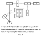
- FIG. 1 An example embodiment of the invention is shown in Fig. 1 .
- This example embodiment allows CLI to be performed under lit conditions.
- the background lighting is completely eliminated, and monochromatic red LED lighting is used to illuminate the subject.
- the exemplary set-up of the camera and other components of the imaging system may also be used for embodiments with regular ambient lighting where the part of the subject being imaged is shrouded to exclude the ambient light, as discussed further below.
- a subject is injected with 18 F-Fluorodeoxyglucose (FDG) (a common beta-emitting radiopharmaceutical).
- FDG F-Fluorodeoxyglucose
- the radiopharmaceutical may be injected systemically, or locally. Commonly, there is a narrow time window of around 60 minutes to 3 hours post-injection for a scan to be performed. This is a result of the pharmacokinetics and radioactive decay of the radiopharmaceutical at the region of interest.
- the second camera (C2) is an ultra-sensitive camera such as a cooled emCCD camera.
- the first camera (C1) one or more monochromatic or colour cameras may be used. By rapidly applying (in any order) sequential red, green and blue illumination and then composing the image, full colour imaging can be provided. The speed at which the illumination is applied is determined by the desired frame rate of the video image.
- use of very low levels of illumination and a single camera may be used to take advantage of the sensitivity of the CLI camera.
- This illumination could be flashed red, green and blue if a colour image is required.
- a large aperture lens with low f number is preferred. This arrangement means that more light can be collected. Usually this is undesirable because it leads to distortions.
- the spatial resolution is sufficiently maintained for CLI, which generally has a comparatively poor spatial resolution, so that the improvement in light input outweighs the loss of spatial resolution.
- the light generated by the radiopharmaceuticals is passed through a beam splitter (BS) such as a dichroic prism that directs the red light to the first camera and the non-red light to the second camera.
- BS beam splitter
- the second camera is also equipped with a band-pass filter (BP) to block any residual red light.
- BP band-pass filter
- the need for the band-pass filter will depend on the performance of the beam-splitter.
- the role of red and blue may be reversed to allow, for example, a surgeon to see deeper into tissue.to direct a portion of the light to the illuminated camera and a portion of the light to the Cerenkov camera.
- C2 is also enclosed within a radiation shield (e.g., lead shielding) (RS) to block any interference from gamma rays or beta-particles.
- RS lead shielding
- the plane of the camera chip within C2 may also be placed parallel to the incoming light to minimize the cross-section exposed to gamma rays or beta-particles.
- Image processing is applied to the two images (I1 and I2) to calibrate the intensity windowing and apply image registration, if required.
- additional imaging processing can be performed on I2 including both spectral and spatial information.
- the Cerenkov image only comes from a restricted field-of-view (such as the tumour within the surgical site) within I2.
- Another example is that the signal within a pixel should fit the expected Cerenkov spectrum.
- the final image (I) is generated by superimposing the calibrated Cerenkov image (I2) on the illuminated image (I1).
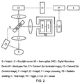
- CLI can be performed in intervals between stroboscopic pulses of light.
- the subject is illuminated by automatic stroboscopic illumination.
- the illumination is white-light illumination with a gated shutter using a digital micro-mirror apparatus (DMD).
- DMD digital micro-mirror apparatus
- the stroboscopic or spectrally separated, lighting may be provided within an optical shroud.
- the stroboscopic or spectrally separated, lighting may be provided in the room.
- This embodiment uses a similar apparatus setup to the embodiment described above.
- the acquisition of the second image is gated off of a signal from the stroboscopic illumination system, as shown by Fig. 2 .
- the gated acquisition is performed using a digital micro-mirror apparatus (DMD).
- DMD digital micro-mirror apparatus
- a trigger connects the DMD to the light source. Connecting the light source and the DMD by the trigger allows light to be directed to one of two cameras for separate imaging of the Cerenkov or structural images.
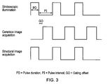
- Fig. 3 shows an example sequence of the stroboscopic pulses and intervals.
- strobe illumination may be >100 Hz and the pulse duration (PD) may be 10-1000 microseconds in an example embodiment.
- Structural image acquisition is performed during the stroboscopic pulse duration.
- the time or gating offset (GO) between the strobe pulse and the acquisition of the second image is sufficiently long to allow for the decay of any induced tissue autofluorescence, and also for any charge on the CCD of the camera to be cleared.
- the pulse duration (PD) is 1000 microseconds
- the pulse interval (PI) is 9000 microseconds
- the gating offset (GO) may be 2000 microseconds and the second (Cerenkov) image acquisition time is 7000 microseconds.
- the pulse duration (PD) is 10 microseconds
- the pulse interval (PI) is 9990 microseconds and so the gating offset (GO) may be 1990 microseconds and the second (Cerenkov) image acquisition time is 8000 microseconds.
- an optical shroud may be used to shield the patient, or the region to be imaged.
- An optical shroud is a shroud or shield that is capable of substantially preventing the penetration of ambient light through the shroud material, so that CLI measurements are possible without turning off room lights.
- the optical shroud is capable of conforming to desirable shapes.
- the optical shroud is made of a material capable of conforming, for example, to the contours of a patient's body.
- the shroud may comprise fabric or metal foil. Other materials that achieve the desired effects are contemplated.
- the shroud may make an optically tight seal with the surface of the patient.
- An optically tight seal may be achieved using, for example, a gel.
- the gel may be placed around the rim of the shroud that comes into contact with the patient. The seal should reduce in wavelength "passband" light levels inside the shroud to a level comparable to, or lower than, the CLI signal.
- the shroud may include built-in gloves to allow, for example, a surgeon access to the region of interest during imaging without breaking the optically tight seal.
- instrument ports and/or instruments may be included.
- an image display may be located on a camera.
- a flexible fiberscope or endoscope may be used for Cerenkov luminescence imaging.
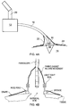
- Fig. 4 schematically shows an embodiment in accordance with the first aspect of the invention in which a fibrescope 10 is used to image tissue at a region of interest 18 (for example a surgical site) during a procedure being carried out on a patient 14.
- a region of interest 18 for example a surgical site
- the fiberscope 10 which is preferably flexible for a surgeon's ease of use, extends from an electron multiplying charge coupled device camera (emCCD) 12 to the region of interest 18 on the patient 14. It is envisaged that the fibrescope 10 will be held in place by the surgeon or an assistant but in other examples a physical support may be provided.
- the tip 16 of the fiberscope 10 is used for imaging tissue at the region of interest 18.
- the emCCD camera is supported by a boom 20.
- An optical shroud 22 (or opaque drape) surrounds the distal end 16 of the fibrescope 10 and the region of interest 18 so that little or no external light is present inside the optical shroud 22 and external light is prevented from entering the region of interest 18.
- the optical shroud 22 is mounted on the distal end of the fiberscope 10. Sealing of the optical shroud 22 may be provided in the same way as described above for sealing against a patient, for example. Alternative approaches to achieving a light tight seal around the edges of the shroud are discussed below with reference to figs. 5b to 5d . The shroud is also sealed tightly against the fibrescope.
- a skirt or drape 24 may be used to extend over the patient 14 away from the region of interest 18.
- the skirt 24 may be attached to the shroud 22 to help block light from entering the region of interest 18.
- the drape may be attached to a rigid ring and the lower edge of the shroud formed with clasps that can engage a top edge of the ring to form a light tight seal.
- a sponge member below the ring prevents the ring from pressing into the patient's skin and also help to ensure a light tight seal against the skin is maintained.
- Figs. 4c and 4d show alternative arrangements for sealing the shroud to the drape.
- the shroud is connected to the top surface of the drape by a seal that may, for example, be a hook and loop seal, a magnetic seal or an electrostatic seal.
- a seal may, for example, be a hook and loop seal, a magnetic seal or an electrostatic seal.
- the fibrescope extends into the shroud through a light tight port.
- the seal is created without any physical connection and relies instead on a long overlap between a skirt of the shroud and the drape.
- a sponge member is also used to enhance the seal.
- the tip 16 of the fiberscope 10 may be manipulated by, for example, one or more gloves through the optical shroud 22, by a wire through the optical shroud 22, or by having a rigid end part of the fiberscope 10 near the tip 16 so that it is possible to manipulate the tip 16 from outside the shroud 22.
- Other ways of manipulating the tip 16 of the fiberscope 10 will be apparent to the skilled person.
- a light detector and indicator may be used to provide feedback to, for example, a surgeon, to provide information about the light tightness of the optical shroud.
- the light detector is a camera. In some embodiments, this may be the CLI camera.
- An additional detector may be used to prevent damage to the CLI camera if, for example, the level of illumination is too great.
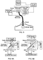
- Fig. 5 shows an alternative embodiment.
- the imaging means comprises two cameras, an emCCD camera for CLI and a colour video camera for illuminated (e.g. anatomical) imaging.
- This figure also illustrates the white light source at the proximal end of the fibrescope that can be used to illuminate the shrouded region of the patient.
- An optical coupler and shutter direct light to the two cameras and shutter is emCCD camera during periods when the interior of the shroud is illuminated.
- the shutter is controlled by a shutter controller to be synchronised with the illumination.
- Fig. 6a shows one exemplary configuration for the optical coupler and shutter.
- a single aspheric lens is used for coupling out of the fibre bundle and focussing on to both cameras.
- a high transmittance beam splitter option is shown.
- Fig. 6b shows another option for the configuration of the optical coupler.
- a modular setup is used with a collimating lens coupling out of the fibre bundle and a focussing lens attached to each camera.
- the high transmittance beam splitter option is shown in this example too.
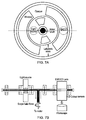
- Figs. 7a and 7b show an alternative shutter arrangement that can be used to shutter both the light source and the emCCD camera in embodiments where these two components are located adjacent to one another.
- the shutter is a rotating disc that is configured to cover both the light source and the emCCD lens.
- the disc is driven by a motor and as it rotates, windows (holes) in the disc, aligned respectively with the light source and the emCCD lens (which are at different radii) mean that the light source and the emCCD camera lens are selectively covered and uncovered.
- the relative positions of the windows ensure that the emCCD lens is covered when the light source is uncovered.
- the emCCD windows are longer than the windows for the light source, to give a longer CLI acquisition period compared with the illuminated image acquisition period.
- Fig. 8 shows a schematic view of an exemplary optical light shield and camera setup in line with the present invention and used for the experiments discussed below.
- an iXon camera is positioned directly above a sample to be imaged (not shown) on a metal mounting plate b.
- An f/1.8 lens c is located beneath the camera and metal mounting plate b.
- a plastic (PVC) tube d extends between the metal mounting plate b and the sample to be imaged.
- the plastic tube d is lined with a low reflectance flock lining e.
- the sample is surrounded by packing foam g, which is covered with a neoprene rubber sponge lining g, in turn covered with stretched elastic h.
- a phantom, or testing replica, for ultra-weak light may be used to calibrate the light system.
- the phantom may use a light emitting diode (LED) with a stack or layers of neutral density filters. If necessary, the LED may be driven with a modulated waveform to further and controllably reduce the output of the LED.
- LED light emitting diode
- Such a phantom may also or alternatively be useful for maintenance and quality control of the light system.
- An iXon Ultra 897 emCCD camera was used to detect the extremely low light levels expected in CLI.
- the source was simulated using a duty cycled LED with neutral density filters and a diffuser.
- An f/2.8 lens was used, though the light levels were scaled to simulate an f/1 lens.
- the target irradiance was 0.013 photons/pixel/s.
- the number of photons produced by the LED was scaled by the duty cycle (proportion of time the LED was on in 1 s) distributed by the collimator into a circular beam with a 25 mm diameter. Once attenuated by neutral density filters it encountered the heavy diffuser. This randomised the direction of each photon resulting in half the photons being emitted at the other side. These photons were now divergent and were spread over 2n sr (a hemisphere). This provided radiance in photons/s/sr/cm 2 , and allowed prediction of the irradiance of the detector.
- the OD4 and OD2 filters were used with a 1/10 duty cycle.
- the camera was used in photon counting mode, which digitized each pixel using a photon threshold in counts, removing the impact of the excess noise factor.
- the camera setup was as follows:
- the signal for a 1 s exposure with the room lights off was 0.0048 photons/pixel. This corresponded to S:N for a 32 x 32 binned pixel of 1.7.
- OD4 and OD2 filters were used with a 1/10 duty cycle.
- Signal for a 1 s exposure with the room lights off was found to be 0.0015 photons/pixel, corresponding to a S:N for a 32 x 32 binned pixel of 2.1.
- the silicone cone shroud provided a good quality seal on the flat surface, but was not sufficiently opaque and allowed light to be transmitted into the shielded area.
- the OD4 and OD2 filter was used with a 1.10 and 1.100 duty cycle.
- the camera setup was as follows:
- the signal for a 1 s exposure with the room lights on was 0.0016 photons/pixel, corresponding to S:N for a 32 x 32 binned pixel of 3.1.
- an appropriate shroud such as a silicone cone with rubber sponge layers around the outside, can be used to shield ambient light to such a level that it is possible to employ CLI with room lights on.
- the camera was set up so that the experiment could be conducted inside a lead enclosure with the operation of the laptop on the other side of a room.
- the camera had the following settings:
- F18 was diluted and distributed into six 0.2 mL experimental wells inside a PerspexTM (PMMA) block. Three control wells with inactive material were also prepared. Fig. 7 illustrates the layout of the experimental wells.
- One control well and one active well with activity 2 ⁇ Ci were covered with 6 mm thick BK7 glass.
- One control well and one active well with activity 2 ⁇ Ci were covered with 6 mm thick BK7 glass and black masking tape.
- the BK7 glass is inset, with the wells under it 6 mm below the level of the other wells as viewed by the camera.
- the black masking tape was placed between the wells and the glass, leaving the glass open for viewing.
- the sample block was prepared and placed under the shielded camera, which was then lowered into place and draped to give a light tight enclosure. Images with the following settings were acquired:
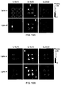
- Fig. 10a shows a set of images taken approximately 15 minutes into the experiment with the lights on and lights off. The positions of the wells have been circled in the top left image using the same scheme as figure 6 . It can be seen that a higher resolution of 32x32 is obtainable in 5 seconds. In addition to the Cherenkov emission interference from high energy rays can be seen as random white pixels that have a signal level beyond the scale used.
- Fig. 10b shows set of images taken approximately 180 minutes into the experiment. Even with the lower signal levels there is no discernible difference due to the room lights. The higher activity wells are still easily visible and the lowest activity well is still discernible.
- Fig. 11 shows the signal photon rate for each active sample well, after correcting for the background by subtracting the corresponding control signal.
- Each point on the graph represents an image of the sample.
- the measured decay constant corresponds to a half-life of 108 minutes.
- the active well covered by glass but not masked produced a similar signal to the open active wells.
- the masked well showed no visible signal, and was quantified to be 10% of the signal obtained from the unmasked well. Therefore it was concluded that the scintillation in optical BK7 glass was insignificant.
Description
- This invention has to do with methods and apparatus for optical imaging of radiopharmaceuticals, in particular Cerenkov Luminescence imaging using a fibrescope.
- Robertson et al. (Phys Med Biol. 2009) observed that certain diagnostic radiopharmaceuticals used in nuclear medicine scans can also be imaged optically. Specifically, radiopharmaceuticals that emit charged particles (e.g., alpha and beta particles) generate detectable light due to the phenomenon of Cerenkov luminescence. Cerenkov photons are due to the deceleration of the charged particle in tissue. Optical imaging of charged particle-emitting radiopharmaceuticals is termed Cerenkov Luminescence Imaging (CLI).
- CLI combines the advantages of optical imaging (including high spatiotemporal resolution and low cost and form factor) with the advantages of nuclear imaging (including molecular specificity and widespread commercial availability of radiopharmaceuticals). Optical imaging will be understood to include ultraviolet to near infra-red wavelengths.
- It would be desirable to use CLI in clinical situations, for example to provide images to inform a surgeon during the course of a procedure. One technical challenge for performing CLI in a clinical scenario is that the Cerenkov spectrum for commonly used diagnostic radioisotopes (particularly those labeled with Fluorine-18) is in the visible spectrum between 400-800 nm. The background illumination in the room would interfere and dominate the Cerenkov spectrum. Also, the illumination would induce tissue auto-fluorescence in the visible spectrum which would overlap with the Cerenkov signal.
- Consequently, CLI is not feasible under typical lighting conditions. All of the CLI applications to date have been in pitch black rooms or chambers where there is no light interference. CLI methods and systems are described in:
US 2011/0250128 ; Holland et al., Mol Imaging, 2011; Carpenter et al., J Nucl. Med, 2012;US2012/0220870 ; and Kothapalli et al., Biomedical Optics Express, Vol 3, . - It has also been proposed to use CLI to create 3D images by means of tomography, as described in
WO 2012/083503 and in Zhong et al, International Journal of Biomedical Imaging, Vol 2011, Article ID 641618.WO 2011/137247 also describes a method of 3D imaging of Cerenkov luminescence, based on the intensity profile of the Cerenkov light. However, these methods also require pitch-black conditions and this are infeasible in a clinical setting. - The journal article "Endoscopic imaging of Cerenkov Luminescence" (Biomedical Express vol. 3 no. 6, 3 May 2012) is directed to a feasibility study of an endoscopic imaging system capable of imaging Cerenkov light emitted from radionuclides.
- The present invention is concerned with methods and apparatus for optical imaging of radiopharmaceuticals that are practical for clinical settings, for example, in an operating theatre.
- In particular, the inventors have identified a need for imaging tissue in situ at an open surgical site or other clinical site on a patient. For example, during a procedure to remove abnormal (e.g. cancerous) tissue from a subject it would be very beneficial for a surgeon to be able to confirm prior to conclusion of the procedure that they have removed all of the abnormal tissue; a common problem in such procedures is that a marginal portion of the abnormal tissue is left behind, which must be removed in a further procedure once it is later detected. A proposal of the present invention is therefore to provide a imaging system and method that use Cerenkov luminescence imaging to inspect the tissue at a clinical site such as an open surgical site to check that the all abnormal tissue (e.g. cancerous cells) has been removed.
- In a first aspect, the invention provides an apparatus configured for optical imaging of Cerenkov luminescence from a region on a subject subsequent to the subject receiving a dose of a radiopharmaceutical, the apparatus comprising:
- an imaging means capable of imaging Cerenkov photons;
- a fibrescope for transmitting light received at a distal end of the fibrescope to a proximal end of the fibrescope, the proximal end of the fibrescope being connected to the imaging means; and
- an optical shroud surrounding the distal end of the fibrescope and, when in use, covering a region of interest, wherein the optical shroud is capable of at least substantially blocking the passage of ambient light.
- The optical shroud is capable of at least substantially (and preferably completely) blocking the passage of ambient light. In some embodiments the shroud is designed to attenuate ambient light by at least 10 to 14 orders of magnitude.
- It is preferred that the ambient light level received by the imaging means should result in a photon flux less than 10 times the photon flux from the radiopharmaceutical, otherwise it may be very difficult or impossible to see the Cerenkov image. More preferably the photon flux resulting from ambient light is no more than 10 times less than the radiopharmaceutical flux. The flux from the radiopharmaceutical (e.g. F18) will typically be between 103 and 104 photons/s/sr/cm2.
- In this way, when the shroud is place over a region of interest (for example, a surgical site), with a bottom edge of the shroud forms a seal against the subject's skin around the region of interest (either directly or using additional sealing parts, for example as discussed below), a light tight enclosure is formed to enable Cerenkov imaging of the region of interest.
- The shroud may be formed of any of a number of suitable materials or combinations of materials that prevent penetration of ambient light to an adequate degree to enable successful Cerenkov imaging. It may for example be a rubberised black-out fabric, a rubber sponge material such as closed cell expanded neoprene, metalised films, opaque moulded polymers.
- In some embodiments, to help ensure a light tight seal of the shroud against the subject, an opaque drape is first placed over the subject, the drape having an opening such that it does not cover the region of interest. A bottom edge of the shroud can then be brought into contact with the drape around the region of interest.
- Rather than rely on the shroud sitting tightly against the drape, it is preferred that sealing means are provided to secure the shroud to the drape. The sealing means may, for example, be physical (e.g. Velcro™), magnetic, vacuum or electrostatic seals. Alternatively the shroud and seal may be physically joined to one another by a connector, such as a rigid ring that is engaged by the shroud and the drape. Another alternative is to engage the seal using an external power source, such as a vacuum line.
- In some embodiments there is a light sensor within the shroud that can be used to confirm whether or not a light tight enclosure has been created. In other embodiments, images collected by the imaging means can be used for this confirmation (especially where the imaging means is configurable to collect illuminated images, as discussed below).
- The imaging means may be a charge coupled device (CCD) camera. A cooled electron-multiplying CCD (emCCD) camera is preferred to acquire the low light level CLI images. Possible alternative imaging means include intensified CCD, photon multiplier tube (PMT) array, or micro-channel plates with electron collection by one or more electrodes.
- When using an emCCD camera to image Cerenkov photons, the EM gain will typically be set to at least 100, preferably at least 200 and more preferably to about 300. Higher EM gains may be used. For example, for photon counting a gain of as much as 1000 might be used. When acquiring the Cerenkov images the emCCD camera will be cooled, typically to -80 to -100 degrees C.
- In some embodiments, the Cerenkov imaging means (e.g. emCCD camera) is housed within a radiation shield to help avoid interference from unwanted radiation, such as gamma rays, or beta particles. Suitable forms of shielding include lead shielding and Boron-filled high density polyethylene for example. Other materials or composite structures that can block the unwanted radiation can also be used.
- The fibrescope comprises a lens mounted on the distal end of a light conduit for conveying an optical signal from the lens to the imaging means. The light conduit will typically be a coherent fibre optic bundle, with the lens mounted on its distal end. The fibrescope may have a conventional construction and will normally be flexible to allow it to be easily manipulated by the operator. The diameter of the lens may be about 1.5cm.In some embodiments, the focus of the lens can be varied. Preferably the adjustment of the lens focus is motorised so that controls can be provided outside the shroud to facilitate focusing the lens when the shroud is in position over a region of interest.
- In some embodiments, the fibre optic bundle within the fibrescope (or the complete fibrescope) is shielded by a radiation shield. Similarly to the shield for the imaging means, this is to help avoid interference from unwanted radiation, such as gamma rays, or beta particles in the fibreglass of the fibrescope. Suitable flexible radiation-shielding materials include, for example, metal-impregnated elastomers.
- In many cases it will be useful for the operator of the apparatus to be able to view an illuminated image (e.g. a white light image) of the region of interest within the light-tight enclosure formed by the shroud before and/or during acquisition of Cerenkov images.
- Prior to acquisition of the Cerenkov image this may be useful, for example, to ensure correct positioning of the fibrescope and correct focus of the lens. During acquisition it may be useful in order to monitor movement of the fibrescope relative to the region of interest and/or to provide sequences of illuminated and Cerenkov images that can be overlaid upon one another e.g. to ensure correct registration of sequential Cerenkov images. This registration of images may be particularly important in some embodiments, where for example the fibrescope is held by a person who is liable to move. The Cerenkov image is typically averaged from multiple frames and if the subsequent frames are not spatially registered with one another then there will be a loss of resolution. Any change in position of the fibrescope relative to the region of interest can be identified in the illuminated image and the registration of the Cerenkov frames corrected accordingly with suitable image processing procedures (e.g. using image processing software).
- In some cases, a surgeon may also want an illuminated image in order that they can conduct a procedure (e.g. excision of tissue) using instruments within the shroud. Particularly in the cases of using an illuminated image pre-Cerenkov acquisition to ensure correct location of the fibrescope, or to give a surgeon visibility of the region of interest to conduct a procedure, the image may conveniently be a video image.
- In order to obtain an illuminated image from within the shroud it is necessary to illuminate the interior of the light tight enclosure formed by the shroud. The preferred approach to illuminate the enclosure is to employ a separate illumination channel in the fibrescope through which light from an illuminated source (e.g. white light source or R/G/B light source, which may be one or more LEDs) can be transmitted from the proximal end to the distal end of the fibrescope to provide an illumination source at the tip of the fibrescope within the shroud. Alternatively, one of more LEDs may be mounted within the shroud, for example on the distal end of the fibrescope.
- It is envisaged that an operator will switch the apparatus between illuminated and Cerenkov imaging modes. Some embodiments may include a third mode for simultaneous illuminated image capture and CLI.
- In embodiments where multiple illuminated and Cerenkov images are to be acquired alternately with one another (i.e. time multiplexed) it is necessary to "switch off" the white/RGB lights during periods of CLI acquisition. In preference to actually switching off the lights (e.g. LEDs), a mechanical shutter may be used to cover the light source(s) during periods of CLI acquisition and to uncover the light source(s) during periods of illuminated image acquisition. This approach has the advantage of near instantaneous "switching off" of the lights, avoiding problems that might otherwise result from the period of time it takes for a light to cease emitting once it is no longer powered.
- The mechanical shutter will be synchronised to the image acquisition sequence. The shutter may, for example, be a rotating disc with regularly spaced cut outs round its circumference so that the disc can intermittently cover and uncover the light source(s). The rotation of the disc can then be controlled to give the desired periods of light and dark within the shroud, with which the illuminated and Cerenkov image acquisitions can be synchronised. Where separate cameras are used for illuminated image acquisition and CLI respectively, a mechanical shutter may also be used for the CLI imaging means (to avoid damage to the imaging means during periods of illuminated image acquisition). The shutter for the CLI imaging means may also be a rotating disc. Conveniently, the CLI imaging means and the light source for illuminating the chamber can be arranged so that a single rotating disc can serve as a shutter for the imaging means and the light source.
- During such time multiplexed illuminated image and CLI acquisition, typically the duration on CLI acquisition periods will be longer than illuminated image acquisition periods to allow time to capture an adequate Cerenkov image, given the much lower light intensity levels. The CLI acquisition period may be many times as long as the illuminated periods, for instance about 3 to 20 times as long. For example, for a 10Hz illuminated video rate, the illuminated period would take 17 ms, with 75 ms of CLI acquisition in-between frames. 8 ms are lost every cycle due to the shutter transition times. The CLI imaging is only enabled whilst the light shutter is firmly closed and not in transition.
- In some embodiments the CLI acquisition does not commence immediately after the light is 'switched off' (e.g. covered by the shutter) to give time for any residual light in the chamber to disperse.
- In some embodiments it may be desirable to employ two separate imaging means, one to capture the illuminated image and the other to capture the CLI image. In other embodiments, a single imaging means captures both images.
- In the case where a single imaging means is used it will normally be desirable to switch the imaging means between an illuminated level image mode and a low light level image mode for capture of the illuminated and CLI images respectively. This is because the types of camera that are sensitive enough to detect Cerenkov photons are likely to be damaged if the same sensitivity settings are used for an illuminated image. Where a single camera is used, the level of light for the illuminated image is preferably low and may be achieved, for example, by using neutral density filters and pulse width modulation of LEDs.
- For example, in the case of an emCCD camera, whilst it will be cooled significantly and the EM gain set to a relatively high level for CLI, the camera will typically be operated in a conventional CCD mode, with no EM gain when capturing illuminated images. Furthermore, in order to avoid ghosting it would be necessary to raise the temperature of the sensor to ambient before cooling it down once more for the next CLI image.
- In some embodiments of the invention, therefore, the imaging means is switched between operating modes (Cerenkov image capture and illuminated image capture modes) during operation, this switching being synchronised with the switching on and off (e.g. by the mechanical shutter) of the light(s) in the chamber as the apparatus switches back and forth between Cerenkov image capture and illuminated image capture.
- Particularly where the apparatus is to be used during a procedure for removing abnormal tissue, examination of the margins, especially the surface of the open region of interest can be important (as noted above). The inventors have recognised that there the sensitivity is reduced by the charged particles at the surface that escape the tissue and therefore cease generating Cerenkov photons. The sensivity of CLI can be increased by placing a Cerenkov radiator on the surface of the tissue so that the escaping charged particles generate Cerenkov light. The Cerenkov radiator should have high refractive index (1.5<RI<2.4), high transmission at short wavelengths (<500 nm), and sufficiently thin to minimize scattering of the charged particles.
- In some embodiments, therefore, it is proposed to use a Cerenkov radiator consisting of a cover slip or mesh with the properties indicated above. The Cernekov radiator can be placed over the tissue surface at the region of interest. The interaction with the cover slip or mesh of charged particles from the tissue surface generates Cerenkov photons and/or scintillation photons that can then be imaged by the imaging means.
- Suitable high refractive index materials for the cover slip or mesh include lead glass, zirconium glass, or tellurite glass. A mesh is advantageous because it can better conform to an irregular-shape tissue surface. The mesh may be formed, for example, using discrete sections of high refractive index material held together by a flexible mesh lattice, for example of polyurethane.
- In some embodiments, to maintain sterility, the fibrescope is housed within a sterile casing. The casing may be connected to the shroud. In one embodiment the sterile casing is made of a flexible material (e.g., silicone) with a transparent window (for example, made of glass) on the distal end. In another embodiment, the sterile casing consists of a hard material (for example, metal) with a transparent window on the distal end, and the casing is sterilisable (for example, by autoclave or ethylene oxide gas).
- In a second aspect, the invention provides a method for optical imaging of Cerenkov luminescence from a region of interest on an object subsequent to the object receiving a dose of a radiopharmaceutical, the apparatus comprising:
- covering the region of interest with a shroud to form a light tight enclosure over the region of interest; and
- capturing a Cerenkov luminescence image of the region of interest using a fibrescope having a distal end within the shroud and a proximal end outside of the shroud connected to an imaging means.
- In some embodiments, the method further comprises illuminating the interior of the shroud with light and capturing an illuminated image of the region of interest whilst the interior of the enclosure is illuminated, the Cerenkov luminescence image being captured when the interior of the enclosure is not illuminated.
- The method may employ the apparatus of the first aspect above, including any one or more of its preferred and optional features discussed above.
- In some embodiments the object is a subject such as a patient undergoing a clinical (e.g. surgical) procedure.
- In other embodiments, the object is a sample or specimen. In this case the shroud may be a flexible light tight shield that is held over the sample, for example on a table top or a tray (e.g. a surgical tray).
- Alternatively, the shroud may be a light tight container such as a sample dish with a lid having opaque walls to exclude ambient light from the inside of the container. Conveniently, the container may be disposable. The distal end of the fibrescope may be exposed to the interior of the container for example through a sealed opening in a wall of the container or the container lid.
- A method and apparatus, not forming part of the present invention, are also described, for optical imaging of Cerenkov luminescence from a subject subsequent to the subject receiving a dose of a radiopharmaceutical, the method comprising the steps of:
- capturing a first image of the subject;
- capturing a second image of Cerenkov luminescence; and superimposing the two images.
- Preferably the first and second images may comprise a sequence of images (e.g. a video).
- Preferably the steps of capturing the first image and the second image are repeated rapidly in sequence, or more preferably simultaneously, so that a video of the subject formed from the overlaid or superimposed images is created. The video rate of the first and second images may vary significantly, for example with the CLI image being semi-static at 0.2 Hz, and the white light image being dynamic at 10Hz.
- A method, not forming part of the present invention, is also described for optical imaging of Cerenkov luminescence from a subject subsequent to the subject receiving a dose of a radiopharmaceutical, the method comprising the steps of:
- illuminating the subject with light of a predetermined range of wavelengths; capturing a first image with a first imaging means; and capturing a second image with a second imaging means, said second image captured at wavelengths distinct from that of the illuminating light.
- Preferably, the methods of the invention include placing an optical shroud or opaque drape to shield the region to be imaged. In this way, it is not necessary to interfere with the lighting in an operating theatre.
- Preferably, the method includes use of a light detector and indicator to determine the light level within the shroud or drape. This makes it possible to check that the surgical site is sufficiently shrouded to perform CLI.
- Preferably, the method includes the step of applying strobed or spectrally separated lighting. Preferably, the strobed or spectrally separated lighting may be applied within the optical shroud or drape. The strobe or spectrally separated lighting may be applied by a light source within the room.
- An apparatus, not forming part of the present invention, is also described for optical imaging of Cerenkov luminescence from a subject subsequent to the subject receiving a dose of a radiopharmaceutical, the apparatus comprising a first imaging means for capturing a first image of the subject, and a second imaging means for capturing a second image of the subject, wherein said second image is captured at wavelengths of light distinct from that of the illuminating light.
- Preferably, the first imaging means images the subject over wavelengths ranging from the ultra-violet to visible to nfra-red.
- Preferably the two images from the first and second imaging means are superimposed to produce a single image for use e.g. by a surgeon performing surgery to remove cancerous tissue that has taken up the radiopharmaceutical.
- Again, preferably the steps of capturing the first image and the second image are repeated rapidly in sequence, or more preferably simultaneously, so that a video of the subject formed from the overlaid or superimposed images is created.
- Preferably, the subject is illuminated only with light at the red end of the spectrum e.g. from monochromatic red or monochromatic blue LED lighting. Preferably, the subject is illuminated only with light in the range of 500-740 nm, preferably in the range 625-740 nm, or in the range 435-500 nm. The skilled person will appreciate that other predetermined ranges of wavelengths of light may be used to illuminate the subject, e.g. red light, or non-contiguous ranges of light (e.g. red light and blue light).
It is beneficial for the subject to be illuminated to allow e.g. a surgeon to be able to operate on the subject. - Red illumination may be preferable to blue illumination since green-to-violet light induces tissue autofluorescence in the visible range.
- Preferably the second imaging means images Cerenkov luminescence to perform CLI. Preferably the second imaging means is ultra-sensitive and is optimised to perform CLI. For example, preferably the second imaging means is cooled to eliminate background noise (commonly called "dark noise"). Preferably the first and second images are calibrated.
- Preferably the light paths feeding the two imaging means pass through a beam-splitter, so that they both image the same region of the subject. The beam-splitter is preferably a dichroic prism.
- Preferably the second imaging means has a band pass filter to block any residual light and to aid in selecting the discrete and distinct wavelengths of light to be imaged. The need for the band pass filter may depend on the performance of the beam-splitter. The light source may also use a filter to further minimize spectral overlap.
- It will be understood by the skilled person that the first and second imaging means can be contained within the same apparatus. Preferably the imaging means is a camera. It will be understood by the skilled person that the imaging means could be a charge-coupled apparatus (CCD) contained within a camera. The first imaging means and the second imaging means may be two different CCDs contained within the same unit. Using two imaging means is preferable because it allows for the spectral response and dynamic range to be selected separately for each image. In addition, strong illumination of a sensitive camera increases the dark noise for a period after illumination. The CCD for the Cerenkov camera could have high quantum efficiency in the near infra-red range. The chip could comprise, for example, an electron multiplying CCD, intensified CCD, photon multiplier tube (PMT) array, or micro-channel plates with electron collection by one or more electrodes.
- Preferably the second imaging means is also enclosed within a radiation shield (e.g. lead shielding or Boron-filled high density polyethylene) to block any interference from unwanted radiation, such as gamma rays, or beta particles.
- Preferably the plane of the imaging means (e.g. CCD) within the second imaging means may also be placed parallel to the incoming light to minimize the cross-section exposed to unwanted radiation, such as gamma rays, or beta particles.
- Preferably image processing is applied to the two images obtained from the first and second imaging means to calibrate the intensity windowing and apply image registration if required. To further segment the image from the second imaging means, additional imaging processing may be performed on this image including both spectral and spatial information. For example, it can be specified that the image from the second imaging means only comes from a restricted field-of-view (e.g. the surgical site) within the image. Another example is that the signal within a pixel should fit the expected spectrum emitted from the radiopharmaceutical (e.g. the Cerenkov spectrum).
- Preferably, an optical shroud or opaque drape is placed to shield the region to be imaged. In this way, it is not necessary to interfere with the lighting in an operating theatre, which is advantageous in case of emergencies.
- Preferably, a light detector and indicator may be used to check that the region to be imaged (e.g. clinical site) is sufficiently shrouded to perform CLI.
- A method, not forming part of the present invention, is also described for optical imaging of Cerenkov luminescence from a subject subsequent to the subject receiving a dose of a radiopharmaceutical, the method comprising the steps of: illuminating the subject with light from a light source;
capturing a first image whilst the subject is illuminated with light from the light source; and
capturing a second image whilst the subject is not illuminated with light from the light source. - Preferably the region of interest is illuminated with light from the light source for the majority of the time. Preferably the light from the light source is emitted in repeated pulses. Preferably strobe illumination should be >100 Hz and the pulses should be 10-1000 microseconds in duration. Strobe illumination at >100 Hz is typically imperceptible e.g. by a surgeon performing on the subject. Whilst the subject is illuminated with this light from the light source, a first image, or series of first images, is obtained of the subject. Then, for short intervals between the pulses of illumination, the light source is switched off so that the subject is not illuminated with light from the light source. Preferably during this interval, the subject is in the dark. During this interval, the second image, or series of second images, of the subject may be obtained. The second image may detect Cerenkov luminescence during this interval. This sequence may be repeated resulting in repetitions or pulses of imaging with light from the light source and imaging Cerenkov luminescence with no light from the light source. The first and second images or sequences of images are then preferably overlaid or superimposed. Preferably a video of sequences of overlaid or superimposed first and second images is produced.
- An apparatus, not forming part of the present invention, is also described for optical imaging of Cerenkov luminescence from a subject subsequent to the subject receiving a dose of a radiopharmaceutical, the apparatus comprising a first imaging means for capturing a first image of the subject, and a second imaging means for capturing a second image of the subject, wherein the first and second imaging means are connected to a stroboscopic illuminating apparatus, and said second image is captured when the subject is not illuminated by the stroboscopic illuminating apparatus.
- Preferably the first image is obtained with a first imaging means and the second image obtained with a second imaging means. However it will be understood that the first and second images may be obtained with the same imaging means. This is important as it may reduce costs, as imaging means suitable for these applications can be expensive.
- Preferably the time offset or gating offset between the strobe pulse and the acquisition of the second image is sufficiently long to allow for the decay of any induced tissue autofluorescence, and also for any charge on the imaging means (e.g. CCD) to be cleared.
- Preferably the acquisition of the second image is gated off of a signal from the illumination system. The gated acquisition can be performed using, for example, a digital micro-mirror apparatus (DMD), a liquid crystal shutter or a spatial light modulator.
- Preferably the subject is illuminated by an automatic stroboscopic illumination. More preferably, the automatic stroboscopic illumination is white-light illumination with a gated shutter, for example, using a Pockels cell or digital micro-mirror apparatus (DMD).
- Preferably the first image is a structural image and the second image is a Cerenkov image. In cases where the structural and Cerenkov images are measured by the same imaging means, the gated acquisition can be performed by treating segments of the signal as the Cerenkov image.
- Preferably the plane of the imaging means (e.g. CCD) may be placed parallel to the incoming light to minimize the cross-section exposed to other sources of radiation such as gamma rays or beta-particles.
- Preferably the first and second images are calibrated. Preferably image processing is applied to the first and second images to calibrate the intensity windowing and apply image registration, if required. To further segment the image, additional imaging processing may be performed on this image including both spectral and spatial information. For example, it can be specified that the signal within a pixel should fit the expected spectrum emitted from the radiopharmaceutical (e.g. the Cerenkov spectrum).
- If two imaging means are used, preferably the second imaging means is ultra-sensitive and is optimised to perform CLI. For example, preferably the second imaging means is a cooled, electron-multiplying CCD camera.
- Preferably the light paths feeding the two imaging means pass through a beam-splitter, so that they both image the same region of the subject. The beam-splitter is preferably a dichroic prism.
- Preferably the second imaging means has a band pass filter to block any residual light and to aid in selecting the discrete and distinct wavelengths of light to be imaged. The need for the band pass filter may depend on the performance of the beam-splitter.
- It will be understood by the skilled person that the first and second imaging means can be contained within the same apparatus. Preferably the imaging means is a camera. It will be understood by the skilled person that the imaging means could be a charge-coupled apparatus (CCD) contained within a camera. The first imaging means and the second imaging means may be two different CCDs contained within the same unit. Using two imaging means is preferable because it allows for the spectral response and dynamic range to be selected separately for each image. The CCD for the Cerenkov camera could have high quantum efficiency in the near infrared range. The chip could comprise, for example, an electron multiplying CCD, intensified CCD, PMT array, or micro-channel plates with electron collection by one or more electrodes.
- Preferably the second imaging means is also enclosed within a radiation shield (e.g. lead shielding or Boron-filled high density polyethylene) to block any interference from gamma rays, or beta-particles.
- Preferably the above aspects are such that they could also be applied in other diagnostic imaging procedures such as endoscopy, capsule endoscopy, imaging for robotic surgery, whole-body imaging, and basic research.
- A phantom, or testing replica, not forming part of the present invention, for ultra-weak light is described. The phantom may use a light emitting diode (LED) with one or more, for example a stack or layers of, neutral density filters through which light from the LED is emitted. Alternatively or additionally, a wavelength selective attenuator may be used in the LED. Reduction of intensity may alternatively or additionally be achieved using pulse width modulation, which may be varied using electronics or software techniques. The phantom may be used to calibrate the light system, and may also or alternatively be useful for maintenance and/or quality control.
- Examples are now described with reference to the accompanying drawings, in which:
-
Fig. 1 shows an example embodiment of the invention; -
Fig. 2 shows an example embodiment of the invention that uses stroboscopic illumination; -
Fig. 3 shows an example sequence of stroboscopic illumination, Cerenkov image acquisition and illuminated structural image (e.g. anatomical image) acquisition of an example embodiment of the invention; -
Fig. 4a schematically shows an example embodiment of the first aspect of the invention using a fiberscope for Cerenkov luminescence imaging; -
Figs. 4b to 4d show variations of the shroud arrangement for the fibrescope embodiment offig. 4a . -
Fig. 5 schematically shows an alternative embodiment that employs two cameras and an optical coupler and shutter to direct light to the two cameras; -
Figs. 6a and 6b show two alternative arrangements for the optical coupler used in the embodiment offig. 5 ; -
Fig. 7a shows a plan view andfig. 7b a cross-section of a rotating disc shutter that can be used to shutter a light source and an emCCD camera. -
Fig. 8 is a schematic view of an optical light shield and camera setup used in experiments to illustrate the principles of embodiments of the invention; -
Fig. 9 shows the layout of sample wells used in the experiments; -
Figs. 10a and 10b show Cerenkov images captured during the experiments; and -
Fig. 11 is a graph of signal photon rate for each of the experimental wells. - An example embodiment of the invention is shown in
Fig. 1 . This example embodiment allows CLI to be performed under lit conditions. In this example embodiment, the background lighting is completely eliminated, and monochromatic red LED lighting is used to illuminate the subject. The exemplary set-up of the camera and other components of the imaging system may also be used for embodiments with regular ambient lighting where the part of the subject being imaged is shrouded to exclude the ambient light, as discussed further below. - In this example embodiment, a subject is injected with 18F-Fluorodeoxyglucose (FDG) (a common beta-emitting radiopharmaceutical). The radiopharmaceutical may be injected systemically, or locally. Commonly, there is a narrow time window of around 60 minutes to 3 hours post-injection for a scan to be performed. This is a result of the pharmacokinetics and radioactive decay of the radiopharmaceutical at the region of interest.
- Two separate cameras (C1 and C2) are used to image the illuminated image and the Cerenkov image respectively. Using two separate cameras allows for the spectral response and dynamic range to be selected separately for each image. The second camera (C2) is an ultra-sensitive camera such as a cooled emCCD camera.. For the first camera (C1), one or more monochromatic or colour cameras may be used. By rapidly applying (in any order) sequential red, green and blue illumination and then composing the image, full colour imaging can be provided. The speed at which the illumination is applied is determined by the desired frame rate of the video image.
- In alternative embodiments, use of very low levels of illumination and a single camera may be used to take advantage of the sensitivity of the CLI camera. This illumination could be flashed red, green and blue if a colour image is required.
- A large aperture lens with low f number is preferred. This arrangement means that more light can be collected. Usually this is undesirable because it leads to distortions. However, the spatial resolution is sufficiently maintained for CLI, which generally has a comparatively poor spatial resolution, so that the improvement in light input outweighs the loss of spatial resolution.
- The light generated by the radiopharmaceuticals is passed through a beam splitter (BS) such as a dichroic prism that directs the red light to the first camera and the non-red light to the second camera. The second camera is also equipped with a band-pass filter (BP) to block any residual red light. The need for the band-pass filter will depend on the performance of the beam-splitter. The role of red and blue may be reversed to allow, for example, a surgeon to see deeper into tissue.to direct a portion of the light to the illuminated camera and a portion of the light to the Cerenkov camera.
- C2 is also enclosed within a radiation shield (e.g., lead shielding) (RS) to block any interference from gamma rays or beta-particles. The plane of the camera chip within C2 may also be placed parallel to the incoming light to minimize the cross-section exposed to gamma rays or beta-particles.
- Image processing (P) is applied to the two images (I1 and I2) to calibrate the intensity windowing and apply image registration, if required. To further segment the Cerenkov image, additional imaging processing can be performed on I2 including both spectral and spatial information. For example, it can be specified that the Cerenkov image only comes from a restricted field-of-view (such as the tumour within the surgical site) within I2. Another example is that the signal within a pixel should fit the expected Cerenkov spectrum. The final image (I) is generated by superimposing the calibrated Cerenkov image (I2) on the illuminated image (I1).
- In another embodiment of the invention, CLI can be performed in intervals between stroboscopic pulses of light. In this example embodiment, the subject is illuminated by automatic stroboscopic illumination. In this embodiment the illumination is white-light illumination with a gated shutter using a digital micro-mirror apparatus (DMD). Other methods of shuttering are contemplated within the scope of the invention. In some embodiments, the stroboscopic or spectrally separated, lighting may be provided within an optical shroud. In some embodiments, the stroboscopic or spectrally separated, lighting may be provided in the room.
- This embodiment uses a similar apparatus setup to the embodiment described above. In this example embodiment the acquisition of the second image is gated off of a signal from the stroboscopic illumination system, as shown by
Fig. 2 . The gated acquisition is performed using a digital micro-mirror apparatus (DMD). In this example where stroboscopic illumination is used, a trigger (TR) connects the DMD to the light source. Connecting the light source and the DMD by the trigger allows light to be directed to one of two cameras for separate imaging of the Cerenkov or structural images. -
Fig. 3 shows an example sequence of the stroboscopic pulses and intervals. In an example embodiment, strobe illumination may be >100 Hz and the pulse duration (PD) may be 10-1000 microseconds in an example embodiment. Structural image acquisition is performed during the stroboscopic pulse duration. In this example embodiment the time or gating offset (GO) between the strobe pulse and the acquisition of the second image is sufficiently long to allow for the decay of any induced tissue autofluorescence, and also for any charge on the CCD of the camera to be cleared. In an example embodiment, if the pulse duration (PD) is 1000 microseconds, the pulse interval (PI) is 9000 microseconds, and so the gating offset (GO) may be 2000 microseconds and the second (Cerenkov) image acquisition time is 7000 microseconds. In another example embodiment, if the pulse duration (PD) is 10 microseconds, the pulse interval (PI) is 9990 microseconds and so the gating offset (GO) may be 1990 microseconds and the second (Cerenkov) image acquisition time is 8000 microseconds. - In some embodiments, an optical shroud may be used to shield the patient, or the region to be imaged. An optical shroud is a shroud or shield that is capable of substantially preventing the penetration of ambient light through the shroud material, so that CLI measurements are possible without turning off room lights. Optionally, the optical shroud is capable of conforming to desirable shapes. Optionally, the optical shroud is made of a material capable of conforming, for example, to the contours of a patient's body. The shroud may comprise fabric or metal foil. Other materials that achieve the desired effects are contemplated. The shroud may make an optically tight seal with the surface of the patient. An optically tight seal may be achieved using, for example, a gel. The gel may be placed around the rim of the shroud that comes into contact with the patient. The seal should reduce in wavelength "passband" light levels inside the shroud to a level comparable to, or lower than, the CLI signal.
- Optionally, the shroud may include built-in gloves to allow, for example, a surgeon access to the region of interest during imaging without breaking the optically tight seal. Alternatively or additionally, instrument ports and/or instruments may be included.
- Alternatively or additionally, an image display may be located on a camera.
- In some embodiments, a flexible fiberscope or endoscope may be used for Cerenkov luminescence imaging.
-
Fig. 4 schematically shows an embodiment in accordance with the first aspect of the invention in which afibrescope 10 is used to image tissue at a region of interest 18 (for example a surgical site) during a procedure being carried out on apatient 14. - As shown in
Fig. 4 , thefiberscope 10, which is preferably flexible for a surgeon's ease of use, extends from an electron multiplying charge coupled device camera (emCCD) 12 to the region ofinterest 18 on thepatient 14. It is envisaged that thefibrescope 10 will be held in place by the surgeon or an assistant but in other examples a physical support may be provided. Thetip 16 of thefiberscope 10 is used for imaging tissue at the region ofinterest 18. - The emCCD camera is supported by a
boom 20. - An optical shroud 22 (or opaque drape) surrounds the
distal end 16 of thefibrescope 10 and the region ofinterest 18 so that little or no external light is present inside theoptical shroud 22 and external light is prevented from entering the region ofinterest 18. Preferably, theoptical shroud 22 is mounted on the distal end of thefiberscope 10. Sealing of theoptical shroud 22 may be provided in the same way as described above for sealing against a patient, for example. Alternative approaches to achieving a light tight seal around the edges of the shroud are discussed below with reference tofigs. 5b to 5d . The shroud is also sealed tightly against the fibrescope. - Optionally, a skirt or drape 24 may be used to extend over the patient 14 away from the region of
interest 18. Theskirt 24 may be attached to theshroud 22 to help block light from entering the region ofinterest 18. - For example, as seen in
fig. 4b , the drape may be attached to a rigid ring and the lower edge of the shroud formed with clasps that can engage a top edge of the ring to form a light tight seal. A sponge member below the ring prevents the ring from pressing into the patient's skin and also help to ensure a light tight seal against the skin is maintained. -
Figs. 4c and 4d show alternative arrangements for sealing the shroud to the drape. Infig. 4c , the shroud is connected to the top surface of the drape by a seal that may, for example, be a hook and loop seal, a magnetic seal or an electrostatic seal. In this example, rather than the fibrescope extends into the shroud through a light tight port. - In the example shown in
fig. 4d , the seal is created without any physical connection and relies instead on a long overlap between a skirt of the shroud and the drape. In this example a sponge member is also used to enhance the seal. - The
tip 16 of thefiberscope 10 may be manipulated by, for example, one or more gloves through theoptical shroud 22, by a wire through theoptical shroud 22, or by having a rigid end part of thefiberscope 10 near thetip 16 so that it is possible to manipulate thetip 16 from outside theshroud 22. Other ways of manipulating thetip 16 of thefiberscope 10 will be apparent to the skilled person. - It is commonly difficult to tell whether an optically tight seal has formed by eye. Accordingly, in some embodiments a light detector and indicator may be used to provide feedback to, for example, a surgeon, to provide information about the light tightness of the optical shroud. In some embodiments, the light detector is a camera. In some embodiments, this may be the CLI camera. An additional detector may be used to prevent damage to the CLI camera if, for example, the level of illumination is too great.
-
Fig. 5 shows an alternative embodiment. In this embodiment the imaging means comprises two cameras, an emCCD camera for CLI and a colour video camera for illuminated (e.g. anatomical) imaging. This figure also illustrates the white light source at the proximal end of the fibrescope that can be used to illuminate the shrouded region of the patient. An optical coupler and shutter direct light to the two cameras and shutter is emCCD camera during periods when the interior of the shroud is illuminated. The shutter is controlled by a shutter controller to be synchronised with the illumination. -
Fig. 6a shows one exemplary configuration for the optical coupler and shutter. In this example a single aspheric lens is used for coupling out of the fibre bundle and focussing on to both cameras. A high transmittance beam splitter option is shown. -
Fig. 6b shows another option for the configuration of the optical coupler. In this example, a modular setup is used with a collimating lens coupling out of the fibre bundle and a focussing lens attached to each camera. The high transmittance beam splitter option is shown in this example too. -
Figs. 7a and 7b show an alternative shutter arrangement that can be used to shutter both the light source and the emCCD camera in embodiments where these two components are located adjacent to one another. The shutter is a rotating disc that is configured to cover both the light source and the emCCD lens. The disc is driven by a motor and as it rotates, windows (holes) in the disc, aligned respectively with the light source and the emCCD lens (which are at different radii) mean that the light source and the emCCD camera lens are selectively covered and uncovered. The relative positions of the windows ensure that the emCCD lens is covered when the light source is uncovered. As best seen infig. 7a , the emCCD windows are longer than the windows for the light source, to give a longer CLI acquisition period compared with the illuminated image acquisition period. -
Fig. 8 shows a schematic view of an exemplary optical light shield and camera setup in line with the present invention and used for the experiments discussed below. In this example, an iXon camera is positioned directly above a sample to be imaged (not shown) on a metal mounting plate b. An f/1.8 lens c is located beneath the camera and metal mounting plate b. A plastic (PVC) tube d extends between the metal mounting plate b and the sample to be imaged. The plastic tube d is lined with a low reflectance flock lining e. The sample is surrounded by packing foam g, which is covered with a neoprene rubber sponge lining g, in turn covered with stretched elastic h. - In some embodiments, a phantom, or testing replica, for ultra-weak light may be used to calibrate the light system. The phantom may use a light emitting diode (LED) with a stack or layers of neutral density filters. If necessary, the LED may be driven with a modulated waveform to further and controllably reduce the output of the LED. Such a phantom may also or alternatively be useful for maintenance and quality control of the light system.
- The skilled person will appreciate that various modification to the specifically described embodiment are possible without departing from the invention. The following examples are used to support certain aspects of the invention.
- An
iXon Ultra 897 emCCD camera was used to detect the extremely low light levels expected in CLI. The source was simulated using a duty cycled LED with neutral density filters and a diffuser. An f/2.8 lens was used, though the light levels were scaled to simulate an f/1 lens. - The target irradiance was 0.013 photons/pixel/s.
- The number of photons produced by the LED was scaled by the duty cycle (proportion of time the LED was on in 1 s) distributed by the collimator into a circular beam with a 25 mm diameter. Once attenuated by neutral density filters it encountered the heavy diffuser. This randomised the direction of each photon resulting in half the photons being emitted at the other side. These photons were now divergent and were spread over 2n sr (a hemisphere). This provided radiance in photons/s/sr/cm2, and allowed prediction of the irradiance of the detector.
Setup Filters Duty Cycle (fraction on) Magnification Predicted Irradiance (photons/pixel/s) Maximum Nominal Minimum 1 OD4 1/10 0.310 1.63 1.44 1.26 2 OD4 1/50 0.310 0.326 0.288 0.252 3 OD4+ OD2 1/10 0.310 0.017 0.014 0.012 4 OD4+ OD2 1/10 0.246 0.019 0.016 0.014 5 OD4+ OD2 1/100 0.246 0.0019 0.0016 0.0014 - For low irradiance measurements, the OD4 and OD2 filters were used with a 1/10 duty cycle. The camera was used in photon counting mode, which digitized each pixel using a photon threshold in counts, removing the impact of the excess noise factor. The camera setup was as follows:
- CCD thermoelectrically cooled to -80 °C
- 1 MHz Gain 3 pre-amplification
- 1000x EM Gain
- 16 x 16 images (32 x 32 binning)
- photon counting threshold = 500
- f/2.8 lens
- 0.5 µs shift speed
- The signal for a 1 s exposure with the room lights off was 0.0048 photons/pixel. This corresponded to S:N for a 32 x 32 binned pixel of 1.7.
- The lower than expected photon counts could have been attributed to the photon counting threshold used and the small, but (now) significant contribution to the background due to scattered light from source leakage, making the signal appear artificially small.
- Turning on room lights led to a 25 x higher background than the signal levels detected from the source, perhaps due to small gaps in the shrouding to surface interface.
- Measurements were taken with duty cycles of 1/2 and 1/5.
- To summarize, it was possible to measure the target irradiance with the room lights off. The photon counting required very high levels of gains and was not very effective. The rubber sponge shroud was good at blocking light. It was found to fold and create gaps at the interface which, combined with the large perimeter, allowed in too much light to make measurements with room lights on.
- OD4 and OD2 filters were used with a 1/10 duty cycle.
- CCD thermoelectrically cooled to -80 °C
- 1 MHz Gain 3 pre-amplification
- 300 x EM Gain
- 16 x 16 images (32 x 32 binning)
- f/2.8 lens
- 0.5 µs shift speed
- Signal for a 1 s exposure with the room lights off was found to be 0.0015 photons/pixel, corresponding to a S:N for a 32 x 32 binned pixel of 2.1.
- Turning on background lights led to a signal that did not correspond with the source, due to the scattering of ambient photons. The image of the source was 5 times brighter than the source radiance and so the source could not be measured with the room lights on.
- 10 times less radiance could be measured with the room lights off (using a duty cycle of 1 to 100). For a 10 second measurement the signal level was 0.019 photons/pixel, giving S:N of 2.1.
- To summarize, it was possible to measure the target irradiance with the room lights off. It was possible to measure 10 times lower radiance using a 10 times longer exposure. The silicone cone shroud provided a good quality seal on the flat surface, but was not sufficiently opaque and allowed light to be transmitted into the shielded area.
- The OD4 and OD2 filter was used with a 1.10 and 1.100 duty cycle. The camera setup was as follows:
- CCD thermoelectrically coled to - 80 °C
- 1 MHz Gain 3 pre-amplification
- 300x EM Gain or 100x EM Gain
- 16 x 16 images (32 x 32 binning)
- f/2.8 lens
- 0.5 µs shift speed
- The signal for a 1 s exposure with the room lights on was 0.0016 photons/pixel, corresponding to S:N for a 32 x 32 binned pixel of 3.1.
- Additional measurements were taken with as low as 10 times less irradiance and 100 x EM Gain. Some of these are shown in the table below.
Source duty cycle EM Gain Integration time(s) Signal (photons/pixel) S: N Magnification 1/10 100 1 0.015 2.2 0.246 1/10 300 1 0.016 3.1 0.246 1/100 100 10 0.017 2.4 0.246 1/100 300 10 0.016 1.9 0.246 - To summarize, it was possible to measure the target irradiance with the room lights on and 100x EM Gain.
- Therefore, it can be concluded that use of an appropriate shroud, such as a silicone cone with rubber sponge layers around the outside, can be used to shield ambient light to such a level that it is possible to employ CLI with room lights on.
- In vitro measurements of Cerenkov radiation emitted from F18 FDG were conducted using an
iXon Ultra 897 emCCD camera. - The camera was set up so that the experiment could be conducted inside a lead enclosure with the operation of the laptop on the other side of a room. The camera had the following settings:
- 50 mm f/1.8 lens
- CCD temperature: -80 °C
- 1 MHz pre-amplifier with a gain setting 3
- 0.5 µs vertical shift speed
- 300x EM Gain
- The field of view is 47x47 mm
- F18 was diluted and distributed into six 0.2 mL experimental wells inside a Perspex™ (PMMA) block. Three control wells with inactive material were also prepared.
Fig. 7 illustrates the layout of the experimental wells. - The liquid volume and initial activity concentration in the active wells is shown in the table below.
Activity (µCi) Volume (µl) Activity concentration (nCi/µl) No. wells 2 200 10 4 1 100 10 1 0.5 200 2.5 1 - One control well and one active well with
activity 2 µCi were covered with 6 mm thick BK7 glass. One control well and one active well withactivity 2 µCi were covered with 6 mm thick BK7 glass and black masking tape. The BK7 glass is inset, with the wells under it 6 mm below the level of the other wells as viewed by the camera. The black masking tape was placed between the wells and the glass, leaving the glass open for viewing. - The sample block was prepared and placed under the shielded camera, which was then lowered into place and draped to give a light tight enclosure. Images with the following settings were acquired:
- 1. 1s integration time, 16x16 resolution (32x32 binning)
- 2. 3s integration time, 16x16 resolution (32x32 binning)
- 3. 5s integration time, 32x32 resolution (16x16 binning)
- Further images with the same settings were taken, with the room lights on and off, at regular intervals throughout the experiment.
- After the experiment each image was exported and the raw data in counts is converted to a signal in photo-electrons (or detected photons) using the following formula:

- Bias Offset = 200 counts
- Conversion Factor = 4.27 electrons/count
- EM Gain = 300
-
Fig. 10a shows a set of images taken approximately 15 minutes into the experiment with the lights on and lights off. The positions of the wells have been circled in the top left image using the same scheme asfigure 6 . It can be seen that a higher resolution of 32x32 is obtainable in 5 seconds. In addition to the Cherenkov emission interference from high energy rays can be seen as random white pixels that have a signal level beyond the scale used. -
Fig. 10b shows set of images taken approximately 180 minutes into the experiment. Even with the lower signal levels there is no discernible difference due to the room lights. The higher activity wells are still easily visible and the lowest activity well is still discernible. -
Fig. 11 shows the signal photon rate for each active sample well, after correcting for the background by subtracting the corresponding control signal. Each point on the graph represents an image of the sample. The measured decay constant corresponds to a half-life of 108 minutes. - All three control samples showed no signal. The signal from the open wells was proportional to their initial activity. The signals showed exponential decay with a half-life matching that of the F18 FDG (110 minutes). Therefore, it was concluded that Cerenkov radiation due to activity of F18 FDG was being measured.
- The active well covered by glass but not masked produced a similar signal to the open active wells. The masked well showed no visible signal, and was quantified to be 10% of the signal obtained from the unmasked well. Therefore it was concluded that the scintillation in optical BK7 glass was insignificant.
- There was significant interference from gamma rays. However, it was shown in principle that higher resolutions are possible if the sensor is shielded from gamma rays and direct particle impingement. Further, it was possible to detect activities as low as 160 nCi (0.8 nCi/µl) with a spatial resolution down to 400 µm.
Claims (15)
- An apparatus configured for optical imaging of Cerenkov luminescence from a region of interest (18) on a subject (14) subsequent to the subject (14) receiving a dose of a radiopharmaceutical, the apparatus comprising:an imaging means (12) capable of imaging Cerenkov photons;a fibrescope (10) for transmitting light received at a distal end (16) of the fibrescope (10) to a proximal end of the fibrescope (10), the proximal end of the fibrescope (10) being connected to the imaging means (12); characterised in that it further comprises,an optical shroud (22) surrounding the distal end (16) of the fibrescope (10) and covering, when in use, said region of interest (18), wherein the optical shroud (22) is capable of at least substantially blocking the passage of ambient fight.
- An apparatus according to claim 1, further comprising an opaque drape to be placed over the subject, the drape having an opening and the bottom edge of the shroud being configured to engage with the drape around the opening.
- An apparatus according to claim 2, comprising sealing means to secure the shroud to the drape, wherein the sealing means is a physical, pneumatic, hydraulic, magnetic or electrostatic seal, or a physical connector.
- An apparatus according to any one of the preceding claims, comprising a light sensor within the shroud.
- An apparatus according to any one of the preceding claims, wherein the fibrescope (10) comprises a lens at the distal end (16) and adjustment of the lens focus is motorised.
- An apparatus according to any one of the preceding claims, comprising a radiation shield for the fibre optic bundle within the fibrescope (10) or the complete fibrescope (10).
- An apparatus according to any one of the preceding claims, comprising an illumination channel in the fibrescope (10) through which light from a light source can be transmitted from the proximal end to the distal end (16) of the fibrescope (10) to provide an illumination source at the tip of the fibrescope (10) within the shroud (22).
- An apparatus according to any one of claims 1 to 6, comprising one or more light sources mounted within the shroud (22).
- Apparatus according to claim 7 or claim 8, comprising a mechanical shutter to cover the light source(s) during periods of Cerenkov Luminescence Imaging, CLI, acquisition and to uncover the light source(s) during periods of illuminated image acquisition, wherein the mechanical shutter is synchronised to the image acquisition sequence.
- Apparatus according to any one of claims 7 to 9, wherein the apparatus is controlled such that duration on Cerenkov Luminescence Imaging, CLI, acquisition periods is longer than illuminated image acquisition periods.
- An apparatus according to any one of the preceding claims, comprising a Cerenkov radiator that can be placed over the tissue surface at the region of interest (18).
- An apparatus according to any one of the preceding claims, wherein the fibrescope (10) is housed in a sterile casing.
- A method for optical imaging of Cerenkov luminescence from a region of interest (18) on a subject (14) subsequent to the subject (14) receiving a dose of a radiopharmaceutical, the method comprising:covering the region of interest (18) with a shroud (22) to form a light tight enclosure over the region of interest (18); andcapturing a Cerenkov luminescence image of the region of interest (18) using a fbrescope (10) having a distal end (16) within the shroud (22) and a proximal end outside of the shroud (22) connected to an imaging means (12).
- The method of claim 13, further comprising illuminating the interior of the shroud (22) with light and capturing an illuminated image of the region of interest (18) whilst the interior of the enclosure is illuminated, the Cerenkov luminescence image being captured when the interior of the enclosure is not illuminated.
- The method of claim 13 or claim 14, wherein the method comprises using the apparatus of any one of claims 1 to 12.
Applications Claiming Priority (4)
| Application Number | Priority Date | Filing Date | Title |
|---|---|---|---|
| US201261679449P | 2012-08-03 | 2012-08-03 | |
| GB201213827A GB201213827D0 (en) | 2012-08-03 | 2012-08-03 | Method and apparatus for imaging |
| US201361763884P | 2013-02-12 | 2013-02-12 | |
| PCT/GB2013/052087 WO2014020359A1 (en) | 2012-08-03 | 2013-08-05 | Fibrescope for optical imaging of radiopharmaceuticals |
Publications (2)
| Publication Number | Publication Date |
|---|---|
| EP2879565A1 EP2879565A1 (en) | 2015-06-10 |
| EP2879565B1 true EP2879565B1 (en) | 2016-10-26 |
Family
ID=46934816
Family Applications (2)
| Application Number | Title | Priority Date | Filing Date |
|---|---|---|---|
| EP13745899.8A Active EP2879566B1 (en) | 2012-08-03 | 2013-08-05 | Specimen chamber for optical imaging of radiopharmaceuticals |
| EP13745898.0A Not-in-force EP2879565B1 (en) | 2012-08-03 | 2013-08-05 | Fibrescope for optical imaging of radiopharmaceuticals |
Family Applications Before (1)
| Application Number | Title | Priority Date | Filing Date |
|---|---|---|---|
| EP13745899.8A Active EP2879566B1 (en) | 2012-08-03 | 2013-08-05 | Specimen chamber for optical imaging of radiopharmaceuticals |
Country Status (7)
| Country | Link |
|---|---|
| US (2) | US20150230696A1 (en) |
| EP (2) | EP2879566B1 (en) |
| JP (2) | JP2015531061A (en) |
| KR (2) | KR20150054783A (en) |
| CN (2) | CN104755014B (en) |
| GB (1) | GB201213827D0 (en) |
| WO (2) | WO2014020360A1 (en) |
Families Citing this family (34)
| Publication number | Priority date | Publication date | Assignee | Title |
|---|---|---|---|---|
| US10201718B2 (en) | 2011-05-19 | 2019-02-12 | The Trustees Of Dartmouth College | Method and system for using Cherenkov radiation to monitor beam profiles and radiation therapy |
| US10940332B2 (en) | 2011-05-19 | 2021-03-09 | The Trustees Of Dartmouth College | Cherenkov imaging systems and methods to monitor beam profiles and radiation dose while avoiding interference from room lighting |
| WO2016176265A1 (en) * | 2015-04-27 | 2016-11-03 | The Trustees Of Dartmouth College | Cherenkov imaging systems and methods for determining radiation dose |
| WO2015037004A1 (en) * | 2013-09-12 | 2015-03-19 | Goji Limited | Temperature measurement arrangement |
| US9395308B2 (en) * | 2013-10-10 | 2016-07-19 | University Of Akron | Apparatus for quantitative measurements of stress distributions from mechanoluminescene materials |
| FR3016998B1 (en) * | 2014-01-29 | 2022-08-26 | Etude Et Realisation De Materiels Electroniques Speciaux Ermes | DEVICE FOR VISUALIZING PHOTON RADIATION, SUITABLE FOR WORKING IN A RADIOACTIVE ENVIRONMENT AND CAMERA USING SUCH DEVICE |
| GB2527359B (en) * | 2014-06-20 | 2020-05-27 | Lightpoint Medical Ltd | Method and apparatus for imaging of low radiance objects |
| CN104027064B (en) * | 2014-06-27 | 2015-11-04 | 中国科学院自动化研究所 | Planar imaging method is peeped based in Cerenkov effect |
| GB2530785A (en) | 2014-10-02 | 2016-04-06 | Lightpoint Medical Ltd | Method and apparatus for imaging of radiation sources |
| JP6464013B2 (en) * | 2015-04-01 | 2019-02-06 | 富士フイルム株式会社 | Imaging apparatus and method |
| JP6493859B2 (en) * | 2015-04-09 | 2019-04-03 | 公益財団法人若狭湾エネルギー研究センター | Radiation monitoring system |
| CN105435377B (en) * | 2015-12-01 | 2019-04-19 | 南京航空航天大学 | A kind of radiotherapy dosage measuring device and measuring method |
| US20170252579A1 (en) * | 2016-03-01 | 2017-09-07 | Accuray Incorporated | Linear accelerator with cerenkov emission detector |
| KR102379336B1 (en) * | 2016-07-14 | 2022-03-29 | 인튜어티브 서지컬 오퍼레이션즈 인코포레이티드 | Compact Binocular Image Capture Device |
| EP3279699A1 (en) * | 2016-08-05 | 2018-02-07 | Universitätsklinikum Regensburg | Imaging technologies |
| US10709902B2 (en) * | 2016-09-28 | 2020-07-14 | Dung B. Nguyen | Tandem with camera system and method |
| US11200698B2 (en) | 2017-06-01 | 2021-12-14 | Germaine Laboratories, Inc. | Devices and systems for data-based analysis of objects |
| US9983117B1 (en) * | 2017-06-01 | 2018-05-29 | Germaine Laboratories, Inc. | Devices and systems for image-based analysis of test media |
| US10275681B2 (en) | 2017-06-01 | 2019-04-30 | Germaine Laboratories, Inc. | Devices and systems for image-based analysis of test media |
| JP6831463B2 (en) * | 2017-07-14 | 2021-02-17 | 富士フイルム株式会社 | Medical image processing equipment, endoscopy system, diagnostic support equipment, and medical business support equipment |
| GB2565314A (en) * | 2017-08-09 | 2019-02-13 | Lightpoint Medical Ltd | Scintillator products, apparatuses and methods for use in autoradiographic imaging |
| WO2019060375A1 (en) * | 2017-09-19 | 2019-03-28 | Beckman Coulter, Inc. | System for analog light measuring and photon counting in chemiluminescence measurements |
| GB2569371B (en) * | 2017-12-15 | 2022-01-12 | Lightpoint Medical Ltd | Direct detection and imaging of charged particles from a radiopharmaceutical |
| EP3724664B1 (en) * | 2017-12-15 | 2023-08-23 | Bio-Rad Laboratories, Inc. | Combination imaging of assays |
| CA3087055A1 (en) * | 2017-12-21 | 2019-06-27 | Ecolab Usa Inc. | Blackened optical component without fluorescence |
| JP2021510313A (en) * | 2018-01-10 | 2021-04-22 | ケムイメージ コーポレーション | Time-correlated light source modulation for endoscopy |
| CN109297995A (en) * | 2018-11-28 | 2019-02-01 | 江苏康众数字医疗科技股份有限公司 | A kind of resolution ratio adjustable type particle projection imaging system |
| EP3911940A4 (en) * | 2019-01-17 | 2022-10-26 | Moleculight Inc. | Modular system for multi-modal imaging and analysis |
| IL265914B (en) * | 2019-04-08 | 2020-11-30 | Convergent R N R Ltd | System and method for optimizing radiotheraphy treatments |
| US20220244228A1 (en) * | 2019-04-25 | 2022-08-04 | The Regents Of The University Of California | System and method for high-throughput radio thin layer chromatography analysis |
| DE102019208833A1 (en) * | 2019-06-18 | 2020-12-24 | Robert Bosch Gmbh | Method for marking plant image information, in particular for agricultural purposes |
| CN112363198B (en) * | 2020-10-27 | 2022-08-02 | 苏州易奥秘光电科技有限公司 | Spherical bidirectional optical fiber sensing probe |
| KR102507169B1 (en) * | 2020-12-30 | 2023-03-06 | 한남대학교 산학협력단 | Image plate scanning device |
| CN114984462B (en) * | 2022-04-15 | 2024-03-26 | 南京航空航天大学 | Cerenkov light dose monitoring method and device based on multichannel imaging |
Family Cites Families (33)
| Publication number | Priority date | Publication date | Assignee | Title |
|---|---|---|---|---|
| CH505393A (en) * | 1969-09-29 | 1971-03-31 | Bbc Brown Boveri & Cie | Device for measuring the energy of electrically charged particles or for generating electrically charged particles of a certain energy and method for operating this device |
| US3600578A (en) * | 1969-10-07 | 1971-08-17 | Atomic Energy Commission | Reactor power level sensing device using cherenkov radiation |
| US4529296A (en) * | 1983-07-11 | 1985-07-16 | Phase One Products Corporation | Combination shipping carton and light-tight photographic film loading station |
| JP2636259B2 (en) * | 1987-09-16 | 1997-07-30 | オリンパス光学工業株式会社 | Radiation detection endoscope |
| JP2731170B2 (en) * | 1988-08-10 | 1998-03-25 | オリンパス光学工業株式会社 | Radiation detection endoscope |
| JPH04287580A (en) * | 1991-03-18 | 1992-10-13 | Hitachi Ltd | X-ray image pickup method and device, and fluorescent plate and cooling type ccd camera |
| US5388593A (en) * | 1991-11-04 | 1995-02-14 | Marshfield Medical Research & Education Foundation | Surgical drape for endoscopy |
| US5496259A (en) * | 1993-09-13 | 1996-03-05 | Welch Allyn, Inc. | Sterile protective sheath and drape for video laparoscope and method of use |
| US5728041A (en) * | 1996-04-10 | 1998-03-17 | Lone Star Medical Products, Inc. | Isolator for use in surgery or as a clean room and method of using the same |
| JPH1082862A (en) * | 1996-09-10 | 1998-03-31 | Mitsubishi Heavy Ind Ltd | Charged particle measuring device |
| JPH114802A (en) * | 1997-06-17 | 1999-01-12 | Asahi Optical Co Ltd | Focus adjusting device of endoscope |
| ATE391451T1 (en) * | 1998-01-26 | 2008-04-15 | Massachusetts Inst Technology | ENDOSCOPE FOR CAPTURE FLUORESCENCE IMAGES |
| US6677984B2 (en) * | 1999-11-30 | 2004-01-13 | Pentax Corporation | Electronic endoscope system |
| US6775567B2 (en) * | 2000-02-25 | 2004-08-10 | Xenogen Corporation | Imaging apparatus |
| JP2003315943A (en) * | 2002-04-26 | 2003-11-06 | Fuji Photo Film Co Ltd | Radiograph reader and light leakage diagnosing method therefor |
| US20050143664A1 (en) * | 2003-10-09 | 2005-06-30 | Zhongping Chen | Scanning probe using MEMS micromotor for endosocopic imaging |
| US8260389B2 (en) * | 2003-10-15 | 2012-09-04 | Hegln (Dalian) Pharmaceuticals, Inc. | Bladder function monitoring methods, apparatuses, media and signals |
| WO2005034754A1 (en) * | 2003-10-15 | 2005-04-21 | The University Of British Columbia | Methods and apparatus for urodynamic analysis |
| US20050234526A1 (en) * | 2004-04-14 | 2005-10-20 | Gilhuly Terence J | Systems and methods for detection of disease including oral scopes and ambient light management systems (ALMS) |
| JP4524163B2 (en) * | 2004-09-21 | 2010-08-11 | オリンパス株式会社 | Endoscope storage container |
| FR2883074B1 (en) * | 2005-03-10 | 2007-06-08 | Centre Nat Rech Scient | TWO DIMENSIONAL DETECTION SYSTEM FOR NEUTRON RADIATION |
| JP2009109227A (en) * | 2007-10-26 | 2009-05-21 | Ishida Co Ltd | Inspection device |
| JP2009133759A (en) * | 2007-11-30 | 2009-06-18 | Toshiba Corp | Radiation measuring device |
| JP5052310B2 (en) * | 2007-12-04 | 2012-10-17 | オリンパス株式会社 | Observation device |
| JP2009153859A (en) * | 2007-12-27 | 2009-07-16 | Olympus Medical Systems Corp | Drape for endoscope |
| JP5158882B2 (en) * | 2009-04-30 | 2013-03-06 | 国立大学法人大阪大学 | Neutron detection scintillator and neutron measurement device |
| KR100991716B1 (en) * | 2009-10-22 | 2010-11-04 | 경북대학교 산학협력단 | Optical imaging contrast agents, use and device thereof |
| US20110250128A1 (en) | 2010-04-12 | 2011-10-13 | Colin M Carpenter | Method for tissue characterization based on beta radiation and coincident Cherenkov radiation of a radiotracer |
| EP2593003A4 (en) | 2010-04-30 | 2015-09-16 | Univ Columbia | System, method and computer-accessible medium for performing attenuation-corrected multispectral luminescence tomography of cerenkov and bioluminescent light sources |
| CN101856220B (en) * | 2010-05-14 | 2011-08-24 | 西安电子科技大学 | Quantitative optical molecular tomographic device and reconstruction method |
| WO2012083503A1 (en) * | 2010-12-23 | 2012-06-28 | 中国科学院自动化研究所 | Tomography method and system based on cerenkov effect |
| US10517964B2 (en) | 2011-02-28 | 2019-12-31 | The Board Of Trustees Of The Leland Stanford Junior University | Optical imaging probes, optical imaging systems, methods of optical imaging, and methods of using optical imaging probes |
| CN102335005B (en) * | 2011-07-26 | 2014-02-05 | 中国科学院自动化研究所 | Cerenkov luminescence tomography (CLT) system and method adopting low-dimensional array detection |
-
2012
- 2012-08-03 GB GB201213827A patent/GB201213827D0/en not_active Ceased
-
2013
- 2013-08-05 KR KR1020157005462A patent/KR20150054783A/en not_active Application Discontinuation
- 2013-08-05 EP EP13745899.8A patent/EP2879566B1/en active Active
- 2013-08-05 CN CN201380041119.7A patent/CN104755014B/en not_active Expired - Fee Related
- 2013-08-05 JP JP2015524848A patent/JP2015531061A/en active Pending
- 2013-08-05 KR KR1020157005305A patent/KR20150058174A/en not_active Application Discontinuation
- 2013-08-05 WO PCT/GB2013/052088 patent/WO2014020360A1/en active Application Filing
- 2013-08-05 WO PCT/GB2013/052087 patent/WO2014020359A1/en active Application Filing
- 2013-08-05 EP EP13745898.0A patent/EP2879565B1/en not_active Not-in-force
- 2013-08-05 US US14/419,183 patent/US20150230696A1/en not_active Abandoned
- 2013-08-05 JP JP2015524847A patent/JP6325540B2/en active Active
- 2013-08-05 CN CN201380041336.6A patent/CN104780829B/en not_active Expired - Fee Related
- 2013-08-05 US US14/419,193 patent/US9816947B2/en active Active
Also Published As
| Publication number | Publication date |
|---|---|
| JP2015525645A (en) | 2015-09-07 |
| GB201213827D0 (en) | 2012-09-19 |
| EP2879566A1 (en) | 2015-06-10 |
| US9816947B2 (en) | 2017-11-14 |
| JP6325540B2 (en) | 2018-05-16 |
| WO2014020360A1 (en) | 2014-02-06 |
| KR20150054783A (en) | 2015-05-20 |
| CN104780829B (en) | 2017-07-11 |
| CN104755014B (en) | 2018-05-01 |
| CN104755014A (en) | 2015-07-01 |
| US20150241363A1 (en) | 2015-08-27 |
| KR20150058174A (en) | 2015-05-28 |
| CN104780829A (en) | 2015-07-15 |
| US20150230696A1 (en) | 2015-08-20 |
| EP2879565A1 (en) | 2015-06-10 |
| WO2014020359A1 (en) | 2014-02-06 |
| JP2015531061A (en) | 2015-10-29 |
| EP2879566B1 (en) | 2019-12-11 |
Similar Documents
| Publication | Publication Date | Title |
|---|---|---|
| EP2879565B1 (en) | Fibrescope for optical imaging of radiopharmaceuticals | |
| US11039090B2 (en) | Multipurpose imaging and display system | |
| KR101173325B1 (en) | Lymph node detector | |
| CN101744611B (en) | Apparatus for photodynamic therapy and photo detection | |
| US20200400500A1 (en) | Pulsed illumination in a fluorescence imaging system | |
| CN106999021A (en) | Method and part for multispectral imaging | |
| KR101784970B1 (en) | Triple hybrid imaging apparatus for laparoscopic sentinel lymph node dissection | |
| KR101852181B1 (en) | hybrid imaging apparatus for laparoscopic surgery | |
| EP3987762A1 (en) | Hyperspectral and fluorescence imaging with topology laser scanning in a light deficient environment | |
| GB2254417A (en) | Photodynamic laser detection for cancer diagnosis | |
| US10413619B2 (en) | Imaging device | |
| CN104274146A (en) | Endoscope system and method for operating the same | |
| CN107405053A (en) | Endoscopic system | |
| US20200297294A1 (en) | Direct detection and imaging of charged particles from a radiopharmaceutical | |
| CN100443044C (en) | Device for the detection and characterization of biological tissue | |
| JP2004032068A (en) | Apparatus for imaging entire face | |
| KR20070076153A (en) | Fluorescence video system for the diagnosis of skin | |
| KR102057959B1 (en) | An integrated optical/gamma hybrid imaging apparatus for surgical operation | |
| WO2018186518A1 (en) | Triple fusion imaging apparatus for laparoscopic surgery | |
| KR102163226B1 (en) | Dental imaging apparatus and method for imaging teeth using the same | |
| Domański et al. | Medical test of multilaser mammoscope for breast cancer diagnosis |
Legal Events
| Date | Code | Title | Description |
|---|---|---|---|
| PUAI | Public reference made under article 153(3) epc to a published international application that has entered the european phase |
Free format text: ORIGINAL CODE: 0009012 |
|
| 17P | Request for examination filed |
Effective date: 20150225 |
|
| AK | Designated contracting states |
Kind code of ref document: A1 Designated state(s): AL AT BE BG CH CY CZ DE DK EE ES FI FR GB GR HR HU IE IS IT LI LT LU LV MC MK MT NL NO PL PT RO RS SE SI SK SM TR |
|
| AX | Request for extension of the european patent |
Extension state: BA ME |
|
| DAX | Request for extension of the european patent (deleted) | ||
| GRAP | Despatch of communication of intention to grant a patent |
Free format text: ORIGINAL CODE: EPIDOSNIGR1 |
|
| INTG | Intention to grant announced |
Effective date: 20160518 |
|
| RAP1 | Party data changed (applicant data changed or rights of an application transferred) |
Owner name: LIGHTPOINT MEDICAL LTD |
|
| GRAS | Grant fee paid |
Free format text: ORIGINAL CODE: EPIDOSNIGR3 |
|
| GRAA | (expected) grant |
Free format text: ORIGINAL CODE: 0009210 |
|
| AK | Designated contracting states |
Kind code of ref document: B1 Designated state(s): AL AT BE BG CH CY CZ DE DK EE ES FI FR GB GR HR HU IE IS IT LI LT LU LV MC MK MT NL NO PL PT RO RS SE SI SK SM TR |
|
| REG | Reference to a national code |
Ref country code: GB Ref legal event code: FG4D |
|
| REG | Reference to a national code |
Ref country code: CH Ref legal event code: EP |
|
| REG | Reference to a national code |
Ref country code: AT Ref legal event code: REF Ref document number: 839384 Country of ref document: AT Kind code of ref document: T Effective date: 20161115 |
|
| REG | Reference to a national code |
Ref country code: IE Ref legal event code: FG4D |
|
| REG | Reference to a national code |
Ref country code: DE Ref legal event code: R096 Ref document number: 602013013244 Country of ref document: DE |
|
| REG | Reference to a national code |
Ref country code: LT Ref legal event code: MG4D |
|
| PG25 | Lapsed in a contracting state [announced via postgrant information from national office to epo] |
Ref country code: LV Free format text: LAPSE BECAUSE OF FAILURE TO SUBMIT A TRANSLATION OF THE DESCRIPTION OR TO PAY THE FEE WITHIN THE PRESCRIBED TIME-LIMIT Effective date: 20161026 |
|
| REG | Reference to a national code |
Ref country code: NL Ref legal event code: MP Effective date: 20161026 |
|
| REG | Reference to a national code |
Ref country code: AT Ref legal event code: MK05 Ref document number: 839384 Country of ref document: AT Kind code of ref document: T Effective date: 20161026 |
|
| PG25 | Lapsed in a contracting state [announced via postgrant information from national office to epo] |
Ref country code: LT Free format text: LAPSE BECAUSE OF FAILURE TO SUBMIT A TRANSLATION OF THE DESCRIPTION OR TO PAY THE FEE WITHIN THE PRESCRIBED TIME-LIMIT Effective date: 20161026 Ref country code: NO Free format text: LAPSE BECAUSE OF FAILURE TO SUBMIT A TRANSLATION OF THE DESCRIPTION OR TO PAY THE FEE WITHIN THE PRESCRIBED TIME-LIMIT Effective date: 20170126 Ref country code: SE Free format text: LAPSE BECAUSE OF FAILURE TO SUBMIT A TRANSLATION OF THE DESCRIPTION OR TO PAY THE FEE WITHIN THE PRESCRIBED TIME-LIMIT Effective date: 20161026 Ref country code: GR Free format text: LAPSE BECAUSE OF FAILURE TO SUBMIT A TRANSLATION OF THE DESCRIPTION OR TO PAY THE FEE WITHIN THE PRESCRIBED TIME-LIMIT Effective date: 20170127 |
|
| PG25 | Lapsed in a contracting state [announced via postgrant information from national office to epo] |
Ref country code: ES Free format text: LAPSE BECAUSE OF FAILURE TO SUBMIT A TRANSLATION OF THE DESCRIPTION OR TO PAY THE FEE WITHIN THE PRESCRIBED TIME-LIMIT Effective date: 20161026 Ref country code: IS Free format text: LAPSE BECAUSE OF FAILURE TO SUBMIT A TRANSLATION OF THE DESCRIPTION OR TO PAY THE FEE WITHIN THE PRESCRIBED TIME-LIMIT Effective date: 20170226 Ref country code: RS Free format text: LAPSE BECAUSE OF FAILURE TO SUBMIT A TRANSLATION OF THE DESCRIPTION OR TO PAY THE FEE WITHIN THE PRESCRIBED TIME-LIMIT Effective date: 20161026 Ref country code: PL Free format text: LAPSE BECAUSE OF FAILURE TO SUBMIT A TRANSLATION OF THE DESCRIPTION OR TO PAY THE FEE WITHIN THE PRESCRIBED TIME-LIMIT Effective date: 20161026 Ref country code: FI Free format text: LAPSE BECAUSE OF FAILURE TO SUBMIT A TRANSLATION OF THE DESCRIPTION OR TO PAY THE FEE WITHIN THE PRESCRIBED TIME-LIMIT Effective date: 20161026 Ref country code: NL Free format text: LAPSE BECAUSE OF FAILURE TO SUBMIT A TRANSLATION OF THE DESCRIPTION OR TO PAY THE FEE WITHIN THE PRESCRIBED TIME-LIMIT Effective date: 20161026 Ref country code: HR Free format text: LAPSE BECAUSE OF FAILURE TO SUBMIT A TRANSLATION OF THE DESCRIPTION OR TO PAY THE FEE WITHIN THE PRESCRIBED TIME-LIMIT Effective date: 20161026 Ref country code: AT Free format text: LAPSE BECAUSE OF FAILURE TO SUBMIT A TRANSLATION OF THE DESCRIPTION OR TO PAY THE FEE WITHIN THE PRESCRIBED TIME-LIMIT Effective date: 20161026 Ref country code: PT Free format text: LAPSE BECAUSE OF FAILURE TO SUBMIT A TRANSLATION OF THE DESCRIPTION OR TO PAY THE FEE WITHIN THE PRESCRIBED TIME-LIMIT Effective date: 20170227 Ref country code: BE Free format text: LAPSE BECAUSE OF FAILURE TO SUBMIT A TRANSLATION OF THE DESCRIPTION OR TO PAY THE FEE WITHIN THE PRESCRIBED TIME-LIMIT Effective date: 20161026 |
|
| REG | Reference to a national code |
Ref country code: DE Ref legal event code: R097 Ref document number: 602013013244 Country of ref document: DE |
|
| PG25 | Lapsed in a contracting state [announced via postgrant information from national office to epo] |
Ref country code: CZ Free format text: LAPSE BECAUSE OF FAILURE TO SUBMIT A TRANSLATION OF THE DESCRIPTION OR TO PAY THE FEE WITHIN THE PRESCRIBED TIME-LIMIT Effective date: 20161026 Ref country code: DK Free format text: LAPSE BECAUSE OF FAILURE TO SUBMIT A TRANSLATION OF THE DESCRIPTION OR TO PAY THE FEE WITHIN THE PRESCRIBED TIME-LIMIT Effective date: 20161026 Ref country code: SK Free format text: LAPSE BECAUSE OF FAILURE TO SUBMIT A TRANSLATION OF THE DESCRIPTION OR TO PAY THE FEE WITHIN THE PRESCRIBED TIME-LIMIT Effective date: 20161026 Ref country code: EE Free format text: LAPSE BECAUSE OF FAILURE TO SUBMIT A TRANSLATION OF THE DESCRIPTION OR TO PAY THE FEE WITHIN THE PRESCRIBED TIME-LIMIT Effective date: 20161026 Ref country code: RO Free format text: LAPSE BECAUSE OF FAILURE TO SUBMIT A TRANSLATION OF THE DESCRIPTION OR TO PAY THE FEE WITHIN THE PRESCRIBED TIME-LIMIT Effective date: 20161026 |
|
| REG | Reference to a national code |
Ref country code: FR Ref legal event code: PLFP Year of fee payment: 5 |
|
| PG25 | Lapsed in a contracting state [announced via postgrant information from national office to epo] |
Ref country code: IT Free format text: LAPSE BECAUSE OF FAILURE TO SUBMIT A TRANSLATION OF THE DESCRIPTION OR TO PAY THE FEE WITHIN THE PRESCRIBED TIME-LIMIT Effective date: 20161026 Ref country code: BG Free format text: LAPSE BECAUSE OF FAILURE TO SUBMIT A TRANSLATION OF THE DESCRIPTION OR TO PAY THE FEE WITHIN THE PRESCRIBED TIME-LIMIT Effective date: 20170126 Ref country code: SM Free format text: LAPSE BECAUSE OF FAILURE TO SUBMIT A TRANSLATION OF THE DESCRIPTION OR TO PAY THE FEE WITHIN THE PRESCRIBED TIME-LIMIT Effective date: 20161026 |
|
| PLBE | No opposition filed within time limit |
Free format text: ORIGINAL CODE: 0009261 |
|
| STAA | Information on the status of an ep patent application or granted ep patent |
Free format text: STATUS: NO OPPOSITION FILED WITHIN TIME LIMIT |
|
| 26N | No opposition filed |
Effective date: 20170727 |
|
| PG25 | Lapsed in a contracting state [announced via postgrant information from national office to epo] |
Ref country code: SI Free format text: LAPSE BECAUSE OF FAILURE TO SUBMIT A TRANSLATION OF THE DESCRIPTION OR TO PAY THE FEE WITHIN THE PRESCRIBED TIME-LIMIT Effective date: 20161026 |
|
| REG | Reference to a national code |
Ref country code: CH Ref legal event code: PL |
|
| PG25 | Lapsed in a contracting state [announced via postgrant information from national office to epo] |
Ref country code: MC Free format text: LAPSE BECAUSE OF FAILURE TO SUBMIT A TRANSLATION OF THE DESCRIPTION OR TO PAY THE FEE WITHIN THE PRESCRIBED TIME-LIMIT Effective date: 20161026 |
|
| PG25 | Lapsed in a contracting state [announced via postgrant information from national office to epo] |
Ref country code: LI Free format text: LAPSE BECAUSE OF NON-PAYMENT OF DUE FEES Effective date: 20170831 Ref country code: CH Free format text: LAPSE BECAUSE OF NON-PAYMENT OF DUE FEES Effective date: 20170831 |
|
| REG | Reference to a national code |
Ref country code: IE Ref legal event code: MM4A |
|
| PG25 | Lapsed in a contracting state [announced via postgrant information from national office to epo] |
Ref country code: LU Free format text: LAPSE BECAUSE OF NON-PAYMENT OF DUE FEES Effective date: 20170805 |
|
| PG25 | Lapsed in a contracting state [announced via postgrant information from national office to epo] |
Ref country code: IE Free format text: LAPSE BECAUSE OF NON-PAYMENT OF DUE FEES Effective date: 20170805 |
|
| REG | Reference to a national code |
Ref country code: FR Ref legal event code: PLFP Year of fee payment: 6 |
|
| PG25 | Lapsed in a contracting state [announced via postgrant information from national office to epo] |
Ref country code: MT Free format text: LAPSE BECAUSE OF NON-PAYMENT OF DUE FEES Effective date: 20170805 |
|
| PGFP | Annual fee paid to national office [announced via postgrant information from national office to epo] |
Ref country code: DE Payment date: 20180805 Year of fee payment: 6 Ref country code: FR Payment date: 20180808 Year of fee payment: 6 |
|
| PGFP | Annual fee paid to national office [announced via postgrant information from national office to epo] |
Ref country code: GB Payment date: 20180801 Year of fee payment: 6 |
|
| PG25 | Lapsed in a contracting state [announced via postgrant information from national office to epo] |
Ref country code: HU Free format text: LAPSE BECAUSE OF FAILURE TO SUBMIT A TRANSLATION OF THE DESCRIPTION OR TO PAY THE FEE WITHIN THE PRESCRIBED TIME-LIMIT; INVALID AB INITIO Effective date: 20130805 |
|
| PG25 | Lapsed in a contracting state [announced via postgrant information from national office to epo] |
Ref country code: CY Free format text: LAPSE BECAUSE OF FAILURE TO SUBMIT A TRANSLATION OF THE DESCRIPTION OR TO PAY THE FEE WITHIN THE PRESCRIBED TIME-LIMIT Effective date: 20161026 |
|
| PG25 | Lapsed in a contracting state [announced via postgrant information from national office to epo] |
Ref country code: MK Free format text: LAPSE BECAUSE OF FAILURE TO SUBMIT A TRANSLATION OF THE DESCRIPTION OR TO PAY THE FEE WITHIN THE PRESCRIBED TIME-LIMIT Effective date: 20161026 |
|
| REG | Reference to a national code |
Ref country code: DE Ref legal event code: R119 Ref document number: 602013013244 Country of ref document: DE |
|
| PG25 | Lapsed in a contracting state [announced via postgrant information from national office to epo] |
Ref country code: TR Free format text: LAPSE BECAUSE OF FAILURE TO SUBMIT A TRANSLATION OF THE DESCRIPTION OR TO PAY THE FEE WITHIN THE PRESCRIBED TIME-LIMIT Effective date: 20161026 |
|
| GBPC | Gb: european patent ceased through non-payment of renewal fee |
Effective date: 20190805 |
|
| PG25 | Lapsed in a contracting state [announced via postgrant information from national office to epo] |
Ref country code: FR Free format text: LAPSE BECAUSE OF NON-PAYMENT OF DUE FEES Effective date: 20190831 Ref country code: AL Free format text: LAPSE BECAUSE OF FAILURE TO SUBMIT A TRANSLATION OF THE DESCRIPTION OR TO PAY THE FEE WITHIN THE PRESCRIBED TIME-LIMIT Effective date: 20161026 Ref country code: DE Free format text: LAPSE BECAUSE OF NON-PAYMENT OF DUE FEES Effective date: 20200303 |
|
| PG25 | Lapsed in a contracting state [announced via postgrant information from national office to epo] |
Ref country code: GB Free format text: LAPSE BECAUSE OF NON-PAYMENT OF DUE FEES Effective date: 20190805 |