EP2879121A1 - Leuchtmodul zur tragen laminare Objekten und Anzeigevorrichtung mit einem solchen Modul - Google Patents
Leuchtmodul zur tragen laminare Objekten und Anzeigevorrichtung mit einem solchen Modul Download PDFInfo
- Publication number
- EP2879121A1 EP2879121A1 EP14191853.2A EP14191853A EP2879121A1 EP 2879121 A1 EP2879121 A1 EP 2879121A1 EP 14191853 A EP14191853 A EP 14191853A EP 2879121 A1 EP2879121 A1 EP 2879121A1
- Authority
- EP
- European Patent Office
- Prior art keywords
- module
- front panel
- electrical contact
- power supply
- pole
- Prior art date
- Legal status (The legal status is an assumption and is not a legal conclusion. Google has not performed a legal analysis and makes no representation as to the accuracy of the status listed.)
- Withdrawn
Links
Images


Classifications
-
- G—PHYSICS
- G09—EDUCATION; CRYPTOGRAPHY; DISPLAY; ADVERTISING; SEALS
- G09F—DISPLAYING; ADVERTISING; SIGNS; LABELS OR NAME-PLATES; SEALS
- G09F13/00—Illuminated signs; Luminous advertising
- G09F13/18—Edge-illuminated signs
-
- F—MECHANICAL ENGINEERING; LIGHTING; HEATING; WEAPONS; BLASTING
- F21—LIGHTING
- F21V—FUNCTIONAL FEATURES OR DETAILS OF LIGHTING DEVICES OR SYSTEMS THEREOF; STRUCTURAL COMBINATIONS OF LIGHTING DEVICES WITH OTHER ARTICLES, NOT OTHERWISE PROVIDED FOR
- F21V21/00—Supporting, suspending, or attaching arrangements for lighting devices; Hand grips
- F21V21/08—Devices for easy attachment to any desired place, e.g. clip, clamp, magnet
- F21V21/096—Magnetic devices
-
- F—MECHANICAL ENGINEERING; LIGHTING; HEATING; WEAPONS; BLASTING
- F21—LIGHTING
- F21V—FUNCTIONAL FEATURES OR DETAILS OF LIGHTING DEVICES OR SYSTEMS THEREOF; STRUCTURAL COMBINATIONS OF LIGHTING DEVICES WITH OTHER ARTICLES, NOT OTHERWISE PROVIDED FOR
- F21V21/00—Supporting, suspending, or attaching arrangements for lighting devices; Hand grips
- F21V21/34—Supporting elements displaceable along a guiding element
- F21V21/35—Supporting elements displaceable along a guiding element with direct electrical contact between the supporting element and electric conductors running along the guiding element
-
- G—PHYSICS
- G09—EDUCATION; CRYPTOGRAPHY; DISPLAY; ADVERTISING; SEALS
- G09F—DISPLAYING; ADVERTISING; SIGNS; LABELS OR NAME-PLATES; SEALS
- G09F13/00—Illuminated signs; Luminous advertising
- G09F13/04—Signs, boards or panels, illuminated from behind the insignia
- G09F13/0418—Constructional details
- G09F13/0431—Signs, boards or panels connected to a pole
-
- G—PHYSICS
- G09—EDUCATION; CRYPTOGRAPHY; DISPLAY; ADVERTISING; SEALS
- G09F—DISPLAYING; ADVERTISING; SIGNS; LABELS OR NAME-PLATES; SEALS
- G09F7/00—Signs, name or number plates, letters, numerals, or symbols; Panels or boards
- G09F7/18—Means for attaching signs, plates, panels, or boards to a supporting structure
- G09F2007/1834—Signs or the like supported by two lateral posts
-
- G—PHYSICS
- G09—EDUCATION; CRYPTOGRAPHY; DISPLAY; ADVERTISING; SEALS
- G09F—DISPLAYING; ADVERTISING; SIGNS; LABELS OR NAME-PLATES; SEALS
- G09F7/00—Signs, name or number plates, letters, numerals, or symbols; Panels or boards
- G09F7/18—Means for attaching signs, plates, panels, or boards to a supporting structure
- G09F2007/1852—Means for attaching signs, plates, panels, or boards to a supporting structure for fastening magnetically or by suction or the like
-
- G—PHYSICS
- G09—EDUCATION; CRYPTOGRAPHY; DISPLAY; ADVERTISING; SEALS
- G09F—DISPLAYING; ADVERTISING; SIGNS; LABELS OR NAME-PLATES; SEALS
- G09F13/00—Illuminated signs; Luminous advertising
- G09F13/18—Edge-illuminated signs
- G09F2013/184—Information to display
- G09F2013/1845—Interchangeable poster
Definitions
- the present invention concerns a lightable module (in the jargon also called "back-lit frame") for supporting laminar objects for decoration or information such as posters, photographs, sheets containing written information or images and the like, suitable for being used in shops or commercial or public settings like, for example, banks, travel agencies, estate agencies, showrooms, offices, shops or museums for displaying, especially in windows, advertising information (mainly relating to the products and services provided by such commercial operations) that are suitably and clearly visible to passers-by also at night or in any case where it is dark, or in at least partial natural or artificial darkness conditions, or furthermore in circumstances in which, in general, visibility is for whatever reason reduced, compromised or not optimal.
- the invention presented here also refers to an advertising display using such a lightable module and suitable for being installed especially in windows of commercial operations like, for example, banks, travel agencies, estate agencies, museums and so on.
- displays are used generally comprising a plurality of lightable modules (better known in the field as "back-lit frames"), aligned with one another along one or more columns or one or more rows, or arranged without any particular logical order, on a pair of electrified metallic support and power supply elements that are parallel to one another and spaced apart, with which the lightable modules are coupled through electrical contact nodes.
- back-lit frames a plurality of lightable modules
- the electrified metallic support and power supply elements of the display structure consist of metallic cables under traction or of structurally rigid metallic rods, arranged according to respective vertical directions and fixed to the floor or ceiling, according to the installation choices, so as to constitute uprights or bearing bodies: such metallic support and power supply elements are electrified thanks to their electrical connection with an electrical energy power source (such as conventionally the power mains) through respective electric cables that make said metallic elements electrified one positively (positive pole) and one negatively (negative pole).
- an electrical energy power source such as conventionally the power mains
- Each known lightable (or back-lit) module comprises a front panel made of at least partly transparent plastic material (usually polymethlymethacrylate or PMMA) and having an inner hidden groove, preferably having a mainly longitudinal extension, as well as lighting means housed in such an inner hidden groove and suitable to be operated in order to light the front panel during night and/or in at least partial natural or artificial darkness conditions, or in conditions of poor or not optimal visibility.
- a front panel made of at least partly transparent plastic material (usually polymethlymethacrylate or PMMA) and having an inner hidden groove, preferably having a mainly longitudinal extension, as well as lighting means housed in such an inner hidden groove and suitable to be operated in order to light the front panel during night and/or in at least partial natural or artificial darkness conditions, or in conditions of poor or not optimal visibility.
- a typical lightable module of advertising displays of the prior art includes wiring or electrical continuity means, connected on one side to the lighting means and, on the other side connected through the electrical contact nodes to the two parallel electrified metallic support and power supply elements of the advertising display, so that the positively electrified metallic element is connected through the respective positive contact node to the positive electric wiring and the negatively electrified metallic element is connected through the respective negative contact node to the negative electric wiring.
- the electrical contact points or nodes are positioned on the opposite outer side edges of the lightable modules so that they receive the power supply of the rail structure made up of the two electrified metallic elements that are in this way separated from one another by a distance exactly equal to the width of the lightable module itself.
- a known rail structure made up of metallic elements that are electrified one positively and the other negatively and in a preferred manner connected to the power mains, can support and power only lightable modules having widths equal to the width determined by the distance apart of the electrified metallic elements of such a rail structure.
- a further drawback of the prior art connected to the mechanical system with which the various lightable modules are stably coupled with the two electrified metallic support and power supply elements, consists of the fact that the constructive composition of the electrical contact nodes involves operations that are complicated and wasteful, particularly in terms of time, when it is wished to separate (and subsequently couple) the lightable modules from (with) the rail supporting structure.
- the main purpose of the current invention is to provide a lightable (or back-lit) module for supporting laminar objects that can be separated/coupled from/with the rail structure of electrified metallic support and power supply elements of an advertising display in a more practical, quicker and easier manner than what is allowed by equivalent known lightable modules.
- a task of the invention is to create a lightable module for supporting laminar objects that can be separated/applied from/to the rail structure of electrified metallic support and power supply elements of an advertising display without difficulty even by an untrained person.
- a second purpose of the invention is to create a lightable module for supporting laminar objects that compared to the prior art involves less points of structural discontinuity when coupled with the electrified metallic support and power supply elements, so that the overall appearance of the advertising displays to which such a lightable module belongs is better, in the sense of being more linear and continuous, with respect to that offered by analogous known displays.
- a further purpose of the present invention is to devise an advertising display that, by using one or more lightable modules for supporting laminar objects, has better installation times and costs than those of known advertising displays of the conventional type currently on the market.
- the last but not least purpose of the current invention is to devise an advertising display that is more versatile in use than known advertising displays.
- the present invention relates to a lightable (or back-lit) module for supporting laminar objects according to the attached claim 1, to which we refer for the sake of brevity.
- the lightable module for supporting laminar objects of the invention can be applied/separated to/from the relative pair of electrified metallic support and power supply elements quicker, easier and in a more practical way than the comparable lightable modules of the prior art.
- the electrical contact nodes with which the front panel is removably coupled at the two electrified metallic support and power supply elements of the advertising display are of the quick release type, comprising magnets (preferred variant embodiment), hooks (or crooks), couplers (for example of the bayonet type), joints and/or similar mechanical coupling systems.
- the lightable module (or back-lit frame) of the present invention comprises electrical contact nodes having a very simple constructive composition, or in any case simpler than those currently used: this aspect simplifies the installation of the lightable modules of the invention on the electrified metallic support and power supply elements of the advertising display.
- the present invention relates to an advertising display using the aforementioned lightable (or back-lit) module according to the attached claim 15, to which we again refer for the sake of simplicity.
- the advertising display of the invention has a more linear, uniform and homogeneous appearance than that of the equivalent known advertising displays: this is due to the fact that the electrical contact nodes are arranged in the rear wall of the front panel of the lightable module of the invention.
- the advertising display of the invention has substantial structural stability, better than that which can be obtained for similar advertising displays of the prior art.
- the present invention can comprise at least one of the preferred features described in the following; these features can be indifferently combined with each other in order to satisfy specific applicative requirements.
- the electrical contact nodes are spaced apart from each other of a predetermined distance having a value equal to said reference distance.
- the reference distance is lower than the width of said front panel.
- the electrical contact nodes are made of metal and define a positive contact pole suitable for connecting the wiring and electrical continuity means with a first positively electrified metallic support and power supply element, and a negative contact pole suitable for connecting the wiring and electrical continuity means to a second negatively electrified metallic support and power supply element.
- the electrical contact nodes are four in number, and are arranged according to the vertices of a square whose side size is equal to the reference distance, the electrical contact nodes are further electrically connected to the lighting means in such a manner that a first pair of electrical contact nodes defines the positive contact pole and a first neutral pole, and a second pair of electrical contact nodes defines the negative contact pole and a second neutral pole, the neutral poles being symmetrically and inversely arranged with respect to each other and the positive contact pole and the negative contact pole being symmetrically and inversely arranged with respect to each other.
- the electrical contact nodes are supported on a rear panel coupled to the rear wall of said front panel.
- the electrical contact nodes defining the positive contact pole and the negative contact pole are connected to the lighting means by means of wiring or electrical continuity means running externally with respect to the front panel.
- the rear support panel has substantially the same surface dimensions as the front panel, the wiring or electrical continuity means being placed internally to the rear panel.
- the electrical contact nodes are coupled to the rear wall of the front panel or to the rear panel by means of fastening means in such a manner as to partly protrude from the rear wall of the front panel or from the rear panel.
- the fastening means comprise at least one means of stable but quick releasable connection selected from the group consisting of magnets, hooks or mechanical couplings and the like.
- the magnet means of stable but quick releasable connection are partly housed in a peripheral recess communicating with the outside and made in the rear wall of the front panel or in the rear panel.
- the fastening means comprise:
- the lighting means and the wiring or electrical continuity means are housed in the inner hidden groove.
- the wiring or electrical continuity means comprise a first electrical connection connecting the lighting means with a positive pole corresponding to one of the electrical contact nodes, and a second electrical connection connecting the lighting means to a negative pole corresponding to another of said electrical contact nodes.
- each of the first and second electrical connection has a first end firmly secured to a terminal washer housed in the peripheral recess and interposed and pressed between a magnet and the front panel and a second end secured from opposite sides to a laminar support plate housed in the inner hidden groove and supporting the lighting means.
- the front panel includes a laminar base substrate made of plastic material at least partially not permeable to light and a laminar screen made of transparent plastic material.
- the laminar base substrate has a white background.
- the laminar screen is laser-marked and/or is suitable to house the laminar objects.
- the electrified metallic support and power supply elements comprises any of the conductive elements selected from the group consisting of wires, rods, bars, profiles and the like.
- the means of stable but quick releasable connection of each electrical contact node protruding from the rear wall of the front panel or the rear panel of a lightable module engage into slots obtained in the front surface of the electrified metallic support and power supply elements.
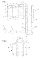
- the lightable module for supporting laminar objects of the invention, as well as the advertising display of the invention are illustrated in application or installation conditions, i.e. potentially coupled together given that it concerns an exploded view, in figure 1 where they are respectively and globally numbered with 1 and 50.
- the lightable (or back-lit) module 1 comprises:
- the electrical contact nodes 6 are coupled with the rear wall, opposite the front wall 2a that in application conditions remains in view, of the front panel 2 and they are of the quick release type so as to allow the easy and immediate removal of the front panel 2 itself from the electrified metallic support and power supply elements 51, 52.
- the electrical contact nodes 6 are contained in the overall dimensions defined by the front panel 2 and the reference distance I that spaces apart the two electrified metallic support and power supply elements 51, 52 and also the predetermined distance K that spaces apart the two electrical contact nodes 6 are less than the width L of the front panel 2: such a constructive provision creates a situation that allows the admissible width of the lightable module of the invention to be advantageously unlinked (or made independent) from the width of the rail power supply bearing structure.
- the lightable module 1 of the invention thanks to the positioning of the electrical contact nodes 6 in the rear wall 2b of the front panel 2 and to the maintaining of a predetermined fixed distance K, constant between such electrical contact nodes 6, makes it possible to position on the rail bearing structure - represented by the two electrified metallic support and power supply elements 51, 52 - lightable modules (or back-lit frames) of any width, unlike what happens in the prior art, with the obvious advantages in terms of versatility of use that this involves for the lightable module of the invention.
- the electrical contact nodes 6 are spaced apart by a predetermined distance K having a value exactly equal to that of the reference distance I with which the electrified metallic support and power supply elements 51, 52 are spaced apart in order to make the coupling of the lightable module 1 of the invention with the latter even easier and quicker.
- the electrical contact nodes 6 are of the metallic type and define a positive contact pole, indicated with "+” in figures 1 and 2 , suitable for connecting the wiring and electrical continuity means 5 with a first of the metallic supporting elements 51, 52, positively electrified, and a negative contact pole, indicated with "-" in figures 1 and 2 , suitable for connecting the wiring and electrical continuity means 5 with a second of the metallic supporting elements (51, 52), negatively electrified.
- the two electrical contact nodes 6 are coupled with the rear wall 2b of the front panel 2 through fastening means, wholly numbered with 7, so as to partially project from such a rear wall 2b of the front panel 2, as can be clearly seen from figure 3 .
- each of the electrical contact nodes 6 comprises any of the stable, but removable, connection components through quick release, selected from the group consisting of magnets (used in the example in the description where they are indicated with 8), hooks or mechanical couplers and similar.
- Figure 3 clearly illustrates that, in the case under examination, the magnets 8, for example made from neodymium, are partially housed in a peripheral recess 9 communicating with the outside and formed in the rear wall 2b of the front panel 2.
- the fastening means 7 introduced above preferably comprise:
- the screw 10 After passing through the through hole 11, engages in the nut screw 12 so as to make the magnet 8 fixedly connected to the front panel 2 and, at the same time, totally contained in the overall dimensions defined by each of the magnets 8.
- the screw 10 is provided with a countersunk flat head 13 that, when the screw 10 itself is totally screwed into the nut screw 12, is housed in an axial seat 14 delimited by a tapered annular wall 15 and formed in the magnet 8 so as to communicate with the outside and be coaxial to the through hole 11, as also highlighted by figure 4 .
- the outer surface 13a of the countersunk flat head 13 of the screw 10 is suitably coplanar to the outer face 8a of the magnet 8 when the screw 10 is totally screwed into the nut screws 11 and 12.
- both of these generic components of the lightable module 1 of the invention are housed in the inner hidden groove 3.
- Figure 1 shows that the wiring or electrical continuity means 5 comprise a first electrical connection 16 (typically an electric wire or other conducting means like a strip of brass, iron and so on) that connects the lighting means 4 to a positive contact pole corresponding to one of the electrical contact nodes 6, and a second electrical connection 17 (again such as a conductive wire, a strip of brass, iron or similar) that connects the lighting means 4 to a negative pole corresponding to the other of the electrical contact nodes 6.
- a first electrical connection 16 typically an electric wire or other conducting means like a strip of brass, iron and so on
- a second electrical connection 17 (again such as a conductive wire, a strip of brass, iron or similar) that connects the lighting means 4 to a negative pole corresponding to the other of the electrical contact nodes 6.
- Each of the aforementioned electrical connections (first and second) 16, 17 has a first end firmly secured to a terminal washer 18, clearly visible in figures 3 and 4 , housed in the peripheral recess 9 and arranged and pressed between each of the magnets 8 and the front panel 2, and a second end secured on opposite sides to a laminar support plate 19, visible in figure 1 , housed in the inner hidden groove 3 and supporting the lighting means 4, notably the LEDs introduced before.
- Figure 3 also illustrates that, only preferably, the front panel 2 comprises a laminar base substrate 20 made from plastic material, like for example methyl methacrylate (or polymethylmethacrylate, also known by the acronym PMMA or by the trade name plexiglas), having a background not permeable to light, for instance a white background, and in general a thickness S 1 having a value, purely for indication, equal to about 3mm.
- plastic material like for example methyl methacrylate (or polymethylmethacrylate, also known by the acronym PMMA or by the trade name plexiglas)
- PMMA polymethylmethacrylate
- plexiglas plexiglas
- the front panel 2 includes a laminar screen 21 firmly secured through the aforementioned fastening means 7 to the laminar base substrate 20 and made from transparent plastic material, again such as methyl methacrylate (or PMMA), laser-marking worked and having a thickness S 2 equal for example to 6 mm, in any case greater than the thickness S 1 of the laminar base substrate 20: the laminar screen 21 receives the laminar objects to make them available and consultable by people going past the advertising display 50.
- transparent plastic material again such as methyl methacrylate (or PMMA)
- the peripheral recess 9 is formed in the laminar base substrate 20, whereas the nut screw 12 is formed in the laminar screen 21.
- the front panel 2 is completed with a perimeter finishing frame (not represented in the following drawings for the sake of simplicity) that hides the inner hidden groove (or track) 3 from view and that improves the appearance of the product.
- a perimeter finishing frame not represented in the following drawings for the sake of simplicity
- Figure 5 shows a first possible variant embodiment of the invention in which the lightable module, now globally numbered with 70, differs from the one just described and indicated with 1 for the number of electrical contact nodes 74 with which the front panel 71 is connected to the electrified metallic support and power supply elements 101, 102 of the advertising display, wholly indicated with 100 and shown in schematic and simplified form in figures 6a-6c .
- the electrical contact nodes 74 are four in number, arranged according to the vertices of a square (or of a matrix 2x2) the side T of which is equal to the reference distance I and electrically connected to the lighting means, wholly indicated with 72, so that a first pair of electrical contact nodes 74 defines the positive contact pole (indicated with "+” in figure 5 ) and a first neutral pole (indicated with N 1 in figure 5 ), and a second pair of electrical contact nodes 74 defines the negative contact pole (indicated with "-" in figure 5 ) and a second neutral pole (indicated with N 2 in figure 5 ): suitably, the neutral poles N 1 and N 2 are symmetrically and inversely arranged with respect to one another and the positive and negative contact poles 74 are symmetrically and inversely arranged with respect to one another.
- each electrified pole 74 is aligned vertically and horizontally with one of the neutral poles N 1 and N 2 .
- the first electrical connection 75 of the wiring means 73 connects the lighting means 72 to the positive contact pole corresponding to one of the electrical contact nodes 74
- the second electrical connection 76 connects the lighting means 72 to the negative pole corresponding to the other of the electrical contact nodes 74.
- the lightable module 70 is rotatable by angles of 90°, in the direction (in this case anti-clockwise) indicated by the arrows F and set by the polarity of the electrified metallic elements 101, 102, from the position with vertical orientation (or North-South) to the position with horizontal orientation (or West-East) and from this back to the position with vertical orientation again in the same direction without losing the electrical continuity between positive contact pole (node) 74 and positively electrified metallic support and power supply element 101 and negative contact pole (node) and negatively electrified metallic support and power supply element 102 and, therefore, without losing its effective functionality.
- a rear support panel 80 is applied to the laminar base substrate 20 to support the four electrical contact nodes 74 which, also in this case, are arranged according to the vertices of a square (or of a matrix 2x2) the side T of which is equal to the reference distance, so that a first pair of electrical contact nodes 74 defines the positive contact pole (indicated with "+” in figure 7 ) and a first neutral pole (indicated with N 1 in figure 7 ), and a second pair of electrical contact nodes 74 defines the negative contact pole (indicated with "-" in figure 7 ) and a second neutral pole (indicated with N 2 in figure 7 ).
- the electrical contact nodes 74 defining the positive contact pole and the negative contact pole are connected to the lighting means 72 by means of a first 75' and a second 76' electrical connection, typically an electric wire or other conducting means like e.g. a brass or iron plate or the like.
- the rear support panel 80 has a lateral size L slightly greater than the side T of the square at whose vertices the electrical contact nodes 74 are arranged, and the first 75' and a second 76' electrical connections run along the rear surface of the laminar base substrate 20 until they reach an inlet interface for entering the laminar base substrate 20 and reaching the lighting means 72.
- the rear support panel 80 has dimensions substantially equal to the surface of the laminar base substrate 20 and internally hosts the electrical connections 75',76'.
- wide lightable modules 70' can be indifferently connected to the couple of electrified metallic support and power supply elements 101, 102 according to a horizontal or vertical arrangement, since the electrical continuity is maintained also in case of 90° rotations.
- the rear panel 80 is made of electrically isolating material, like e.g. wood or plastics.
- the object of the present invention is also an advertising display, globally numbered with 50 or 100 in figures 1 and 2 , suitable in particular for being installed at windows of commercial operations like, for example, banks, travel agencies, estate agencies, museums, showrooms and so on.
- the advertising display 50 or 100 comprises:
- the electrical contact nodes 6 or 74 are firmly secured to the rear wall 2b or 71b opposite the front wall 2a that in application conditions remains in view, of the front panel 2 or 71 and removably coupled with the front surface 51a, 52a or 101a, 102a of the electrified metallic support and power supply elements 51, 52 or 101, 102 so as to allow the easy and immediate removal of the front panel 2, 71 from the electrified metallic support and power supply elements 51, 52 or 101, 102.
- the electrified metallic support and power supply elements 51, 52 or 101, 102 include any of the conductive components selected from the group consisting of cables, rods, bars, profiles and similar.
- each of the electrified metallic support and power supply elements 51, 52 or 101, 102 comprises an upright that is arranged vertically when coupled with the abutment surface R and is electrically connected to the electrical mains S through the interposition of a low voltage power feeder A, for example 6 Volt, 12 Volt or 24 Volt according to the type of lighting means installed on the lightable module.
- a low voltage power feeder A for example 6 Volt, 12 Volt or 24 Volt according to the type of lighting means installed on the lightable module.
- each of the electrical contact nodes 6 or 74 comprises any of the stable connection components, but removable through quick release, selected from the group consisting of magnets 8, hooks or mechanical couplers and similar.
- the embodiment of advertising display of the invention that foresees hooks or mechanical couplers as electrical contact nodes is not accompanied hereafter by any explicative drawing; in any case, the hooks or mechanical couplers protrude from the rear wall of the front panel and engage in slots formed in the front surface of the electrified metallic support and power supply elements.
- Figure 9 highlights, purely as an example, a further variant embodiment of the invention in which the advertising display, now globally indicated with 150, has a more complex and larger composition in this case comprising three pairs of electrified metallic support and power supply elements 151 and 152, 153 and 154, 155 and 156, each of which includes a plurality of lightable modules of the type described earlier and indicated with 1 in figures 1-4 .
- Figure 10 finally shows another constructive solution of the invention in which the advertising display, now globally indicated with 200, comprises two electrified metallic support and power supply elements 201, 202 and a series of lightable modules, each of which indicated with 90, which differ from one another in size.
- the lightable module for supporting laminar objects and the advertising display using or comprising such a lightable module both object of the present invention, achieve the purposes and obtain the advantages mentioned earlier.
- the advertising display can include a different number of pairs of electrified metallic support and power supply elements from that described earlier with reference to the attached figures, such a number being able to vary as desired from one based on the design choices and/or the space available.
- the various electrified metallic support and power supply elements can be not only firmly secured to the abutment surface but also to one another through connecting cross members generally extending horizontally.
- the advertising display comprises a different number of lightable modules from what is visible in the attached figures relative to just a few preferred embodiments that can be made with the inventive concept expressed in the present document; in particular, the number of lightable modules of the advertising display can also vary as desired starting from one.
Landscapes
- Engineering & Computer Science (AREA)
- General Engineering & Computer Science (AREA)
- Physics & Mathematics (AREA)
- General Physics & Mathematics (AREA)
- Theoretical Computer Science (AREA)
- Illuminated Signs And Luminous Advertising (AREA)
Applications Claiming Priority (1)
| Application Number | Priority Date | Filing Date | Title |
|---|---|---|---|
| IT001991A ITMI20131991A1 (it) | 2013-11-28 | 2013-11-28 | Modulo illuminabile per il sostegno di oggetti laminari ed espositore pubblicitario utilizzante tale modulo |
Publications (1)
| Publication Number | Publication Date |
|---|---|
| EP2879121A1 true EP2879121A1 (de) | 2015-06-03 |
Family
ID=49887081
Family Applications (1)
| Application Number | Title | Priority Date | Filing Date |
|---|---|---|---|
| EP14191853.2A Withdrawn EP2879121A1 (de) | 2013-11-28 | 2014-11-05 | Leuchtmodul zur tragen laminare Objekten und Anzeigevorrichtung mit einem solchen Modul |
Country Status (2)
| Country | Link |
|---|---|
| EP (1) | EP2879121A1 (de) |
| IT (1) | ITMI20131991A1 (de) |
Cited By (3)
| Publication number | Priority date | Publication date | Assignee | Title |
|---|---|---|---|---|
| CN105528973A (zh) * | 2016-01-22 | 2016-04-27 | 天津市卡司通展览有限公司 | 新型海报展架装置 |
| IT201700068656A1 (it) * | 2017-06-20 | 2018-12-20 | Isola Antonio Sas Di Isola Antonio | Sistema di pannelli espositivi luminosi |
| FR3142278A1 (fr) | 2022-11-17 | 2024-05-24 | Aratice | Système d’affichage suspendu |
Citations (5)
| Publication number | Priority date | Publication date | Assignee | Title |
|---|---|---|---|---|
| DE202007017609U1 (de) * | 2007-12-14 | 2008-04-10 | Maas & Roos Ag | Leuchtkörpersystem sowie Leuchtkörper für ein Leuchtkörpersystem |
| WO2008099306A1 (en) * | 2007-02-12 | 2008-08-21 | Philips Intellectual Property & Standards Gmbh | Modular electric system |
| DE202008015553U1 (de) * | 2007-12-14 | 2009-02-19 | Maas & Roos Ag | Leuchtreklameanordnung |
| US20110167690A1 (en) * | 2008-09-23 | 2011-07-14 | Asgeir Bjarnason | Light-Emitting Device |
| ES2401191A1 (es) * | 2011-03-29 | 2013-04-17 | Jaime LLADÓ SENDRA | Sistema de sujeción magnética y conexión eléctrica simultánea para accionar luminarias con leds y aparatos eléctricos o electrónicos. |
Family Cites Families (2)
| Publication number | Priority date | Publication date | Assignee | Title |
|---|---|---|---|---|
| US20060291241A1 (en) * | 2005-06-22 | 2006-12-28 | Carmanah Technologies Corp. | Light emitting diode illuminated display panel assembly |
| DE102009055847A1 (de) * | 2009-11-26 | 2011-06-01 | Ledon Lighting Jennersdorf Gmbh | Veränderbare Leuchtvorrichtung |
-
2013
- 2013-11-28 IT IT001991A patent/ITMI20131991A1/it unknown
-
2014
- 2014-11-05 EP EP14191853.2A patent/EP2879121A1/de not_active Withdrawn
Patent Citations (5)
| Publication number | Priority date | Publication date | Assignee | Title |
|---|---|---|---|---|
| WO2008099306A1 (en) * | 2007-02-12 | 2008-08-21 | Philips Intellectual Property & Standards Gmbh | Modular electric system |
| DE202007017609U1 (de) * | 2007-12-14 | 2008-04-10 | Maas & Roos Ag | Leuchtkörpersystem sowie Leuchtkörper für ein Leuchtkörpersystem |
| DE202008015553U1 (de) * | 2007-12-14 | 2009-02-19 | Maas & Roos Ag | Leuchtreklameanordnung |
| US20110167690A1 (en) * | 2008-09-23 | 2011-07-14 | Asgeir Bjarnason | Light-Emitting Device |
| ES2401191A1 (es) * | 2011-03-29 | 2013-04-17 | Jaime LLADÓ SENDRA | Sistema de sujeción magnética y conexión eléctrica simultánea para accionar luminarias con leds y aparatos eléctricos o electrónicos. |
Cited By (3)
| Publication number | Priority date | Publication date | Assignee | Title |
|---|---|---|---|---|
| CN105528973A (zh) * | 2016-01-22 | 2016-04-27 | 天津市卡司通展览有限公司 | 新型海报展架装置 |
| IT201700068656A1 (it) * | 2017-06-20 | 2018-12-20 | Isola Antonio Sas Di Isola Antonio | Sistema di pannelli espositivi luminosi |
| FR3142278A1 (fr) | 2022-11-17 | 2024-05-24 | Aratice | Système d’affichage suspendu |
Also Published As
| Publication number | Publication date |
|---|---|
| ITMI20131991A1 (it) | 2015-05-29 |
Similar Documents
| Publication | Publication Date | Title |
|---|---|---|
| TW200731575A (en) | Solid state lighting units and methods of forming solid state lighting units | |
| JP2012134040A (ja) | 陳列棚の照明器具 | |
| EP2879121A1 (de) | Leuchtmodul zur tragen laminare Objekten und Anzeigevorrichtung mit einem solchen Modul | |
| JP2012506359A (ja) | 絶縁ガラス板 | |
| ATE479180T1 (de) | Elektrophoretische anzeigetafel | |
| US11004366B2 (en) | Illumination display platforms and related methods | |
| CN105546391A (zh) | 一种模块化的led灯体结构 | |
| EP3246904A1 (de) | Rückbeleuchtete popoup-anzeige mit spanngewebe | |
| BE1026256A1 (nl) | Verlichtingsstructuur | |
| CN214176531U (zh) | 一种用于户外电缆的具有动态警示部件的分接箱 | |
| CN204218489U (zh) | 点式带电陈列系统 | |
| CN109243318A (zh) | 一种拼装有静态展示框的led显示屏及其展示方法 | |
| CN211173645U (zh) | 一种展柜的重型开启结构 | |
| CN203338705U (zh) | 教育宣传架 | |
| KR101971703B1 (ko) | 보드 중앙에 음영이 생기지 않도록 하면서 조립이 용이하고 보드의 마크나 문자의 식별이 용이한 돌출간판. | |
| CN104287462B (zh) | 户外太阳能科普展示栏 | |
| CN214948876U (zh) | 一种户外灯光秀灯具升降控制装置 | |
| CN212411526U (zh) | 一种展览展示双面灯箱 | |
| CN105355154A (zh) | 一种用于教育的自发电式显示仪 | |
| CN111436801A (zh) | 工艺品装置 | |
| CN203397642U (zh) | 一种led广告灯箱 | |
| CN214476192U (zh) | 一种轮播式展示装置 | |
| CN204029294U (zh) | 玻璃显示屏 | |
| CN210493521U (zh) | 一种平面设计用作品展示装置 | |
| CN108626651A (zh) | 一种用于会展展示服务的灯光平台及其安装方法 |
Legal Events
| Date | Code | Title | Description |
|---|---|---|---|
| PUAI | Public reference made under article 153(3) epc to a published international application that has entered the european phase |
Free format text: ORIGINAL CODE: 0009012 |
|
| 17P | Request for examination filed |
Effective date: 20141105 |
|
| AK | Designated contracting states |
Kind code of ref document: A1 Designated state(s): AL AT BE BG CH CY CZ DE DK EE ES FI FR GB GR HR HU IE IS IT LI LT LU LV MC MK MT NL NO PL PT RO RS SE SI SK SM TR |
|
| AX | Request for extension of the european patent |
Extension state: BA ME |
|
| RAP1 | Party data changed (applicant data changed or rights of an application transferred) |
Owner name: TECNOSTYL S.R.L. |
|
| STAA | Information on the status of an ep patent application or granted ep patent |
Free format text: STATUS: THE APPLICATION IS DEEMED TO BE WITHDRAWN |
|
| 18D | Application deemed to be withdrawn |
Effective date: 20151204 |