EP2878931A1 - Sensor und Verfahren zum wahlweisen Anschließen von zwei unterschiedlichen Seiten - Google Patents
Sensor und Verfahren zum wahlweisen Anschließen von zwei unterschiedlichen Seiten Download PDFInfo
- Publication number
- EP2878931A1 EP2878931A1 EP14188503.8A EP14188503A EP2878931A1 EP 2878931 A1 EP2878931 A1 EP 2878931A1 EP 14188503 A EP14188503 A EP 14188503A EP 2878931 A1 EP2878931 A1 EP 2878931A1
- Authority
- EP
- European Patent Office
- Prior art keywords
- sensor
- housing
- connections
- terminals
- connection
- Prior art date
- Legal status (The legal status is an assumption and is not a legal conclusion. Google has not performed a legal analysis and makes no representation as to the accuracy of the status listed.)
- Granted
Links
Images


Classifications
-
- G—PHYSICS
- G01—MEASURING; TESTING
- G01D—MEASURING NOT SPECIALLY ADAPTED FOR A SPECIFIC VARIABLE; ARRANGEMENTS FOR MEASURING TWO OR MORE VARIABLES NOT COVERED IN A SINGLE OTHER SUBCLASS; TARIFF METERING APPARATUS; MEASURING OR TESTING NOT OTHERWISE PROVIDED FOR
- G01D11/00—Component parts of measuring arrangements not specially adapted for a specific variable
- G01D11/24—Housings ; Casings for instruments
- G01D11/245—Housings for sensors
Definitions
- the invention relates to a sensor whose connection is optionally accessible from two sides, and to a method for selectively connecting a sensor according to the preamble of claim 1 or 11.
- Various sensor principles are known for acquiring information from a surveillance area.
- a large family of sensors are the optoelectronic sensors that use light to extract such information.
- other wavelengths are also used, for example in radar or microwave sensors, or other physical interactions, such as in capacitive, inductive or ultrasound-based sensors.
- the sensors must provide connections in order to be parameterized, to output measurement results and not least to be supplied with power. Since this is not possible wirelessly in the vast majority of cases, cables must be routed to connections of the sensors and from there to the inside of their housing. This creates difficulties in some operating and assembly situations because the connections must remain accessible.
- a conventional sensor does not form a smooth surface on the side or sides where terminals are located, and therefore can not be flush with a wall or other flat mounting surface on those sides.
- connection area in a rotatable corner piece of the sensor housing.
- the corner piece can be optionally rotated in two different positions, in which the connection in each case on a different side surface of the housing located.
- the direction in which the connection region of the sensor points, depending on the desired operating situation can be adjusted.
- only a single connection is provided. Additional connections are not readily possible because, for example, two adjacent cable glands of the corner piece would block the rotation.
- shielding EMC
- the actual functional elements of the sensor are housed in a main housing part.
- the housing also has a relatively movable to the main housing part connecting part.
- the invention is then based on the basic idea of accommodating a plurality of connections on the connection part, so that these connections are accessible from different sides, depending on the position of the movable connection part.
- the invention has the advantage that connection and mounting of the sensor are facilitated, because there is a choice in which direction the terminals point. This allows the sensor to be flush mounted to a flat surface with each side of the case, without disturbing any connections or associated wires. This flexible, variable connection option is achieved with minimal effort and space requirements.
- connection part preferably has a common passage in order to guide lines from the three connections into the interior of the housing.
- the lines from the three terminals are brought together in the common implementation on an axis. This reduces the number of feedthroughs required and allows the connector to rotate about the common axis with respect to the main body.
- the common implementation is preferably cylindrical. As a result, a rotation of the connecting part relative to the main housing part is supported, wherein the center axis of the cylinder forms the axis of rotation.
- the common feedthrough preferably has three chambers separated from one another in order to each guide a line from one of the three connections.
- the cables are so compact in a small space and still guided with a safe EMC chamber separation. This prevents mutual interference of the signals on the lines.
- the joint passage is preferably formed as a double-walled cylinder having a first chamber in the interior and further chambers as separated from each other by a wall portions of the concentric circumferential region between the two lateral surfaces of the double cylinder.
- a pipe then runs centrally on the center axis of the cylinder.
- the further chambers form a concentric circular ring around the first chamber, which they in particular share evenly.
- each additional camera therefore preferably takes up 180 ° of the circular ring.
- the further chambers by walls extending in the height direction of the cylinder, which in the cross-sectional view connects the double walls in each case on a diameter of the circular surface of the cylinder.
- the three terminals are preferably arranged in a row. As a result, the connections are easily accessible, and cables can be sorted out to the sensor.
- the middle connection is preferably connected to a line extending through the first chamber, and the further connections are preferably connected to a respective line extending through a respective further chamber.
- the outwardly middle port is thereby connected in the implementation with an equally central, central line.
- the further lines are located symmetrically to the sides of the central lines in the concentric further chambers formed around the central first chamber.
- the connections preferably comprise a supply connection and two Profinet connections.
- the supply in particular a voltage connection, is preferably a supply with possible switching inputs and outputs.
- the Profinet connections are preferably made in a standard size, for example as M12 connections.
- the supply connection is located in the middle with two laterally arranged Profinetan ensuren. Then surrounded in the Passing the Profinet lines symmetrical and concentric in the other chambers, the supply line in the central first chamber.
- the leadership in safe EMC chambers is particularly advantageous in Profinet, because otherwise Profinet would be prone to failure with its high data transfer rate.
- the housing is preferably formed substantially cuboid, and the connection part forms a rotatable corner piece of the cuboid.
- the housing thus has a front and back and four side surfaces, which are each at least substantially flat. Additional structures, such as a mirror attachment, or rounding and similar design elements, which lead away from the cuboid shape, but are conceivable.
- the rotatable connection part makes it possible in a particularly simple way to make the connections accessible from different sides of the housing. For example, a 90 ° turn causes connectors to be rotated from one side to the front or back, while a 180 ° rotation will twist the connectors from the right or left side to the bottom or top side.
- the housing preferably has an EMC chamber which shields the area of the connection part from the rest of the sensor. This is achieved for example by an additional wall inside the housing. The connection area is thereby shielded in both directions.
- FIG. 1 shows a three-dimensional view of a sensor 10, the housing 12 has a housing main part 14 with the essential functional components of the sensor 10 and a connecting part 16 with three terminals 18, 20, 22.
- the illustrated sensor 10 is a bar code scanner whose scanning beam is guided over a mirror of an attachment 24.
- the invention also encompasses other sensors, for example camera-based code readers with an image sensor and an evaluation unit which identifies and decodes code areas in the recorded image data, cameras for automatic inspection of object properties or general optoelectronic sensors such as laser scanners, light grids, light barriers or light scanners.
- light-based sensors as exemplified by way of example. On the respective, known per se sensor principle will not be discussed at this point.
- the terminals 18, 20, 22 serve to exchange data with the sensor 10 and to supply it.
- the center port 18 is for a supply line while the two outer ports 20, 22 are M12 Profinet ports. This arrangement and type of terminals 18, 20, 22 is preferred, but still to be understood as an example.
- the terminals 18, 20, 22 and the cables connected thereto in the lateral position of the connecting part 16 according to FIG. 1 disturb, for example, if there is a wall on the right.
- This arrangement and orientation of the terminals 18, 20, 22, however, is advantageous if, for example, the sensor rests with its underside.
- the connecting part 16 can be rotated relative to the housing main part 14 so that the terminals 18, 20, 22 point in a different direction.
- FIG. 2 illustrates the case after a rotation of the connecting part 16 by 180 °.
- the terminals 18, 20, 22 now point downwards, so that the sensor 10 offers a smooth end surface to the right.
- the sensor 10 can be mounted in a corner of the room with direct contact with a wall on the right.
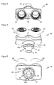
- FIGS. 3 to 5 represent the connection part 16 in a three-dimensional view
- FIG. 3 an external view of the terminals 18, 20, 22,
- FIG. 5 a view from the inside to a common passage 26 for the lines from the terminals 18, 20, 22 into the interior of the sensor 10
- FIG. 4 an intermediate perspective to better understand the structure of the connector 16.
- the connecting part 16 has outwardly three circular passages 18, 20, 22, which are provided with the same reference numerals as the corresponding arranged thereon, but in the FIGS. 3 to 5 Not shown terminals 18, 20, 22.
- the bushings 18, 20, 22 are guided inwardly toward an axis of the common passage 26.
- the common bushing 26 is cylindrically shaped as a whole and thus defines the axis of rotation for the rotation of the connecting part 16 relative to the housing main part 14.
- the joint implementation 26 not only provides a common guide for the lines of all connections, but at the same time a chamber separation for the individual lines.
- the bushing 26 has the overall shape of a concentric double cylinder.
- the inner circumferential surface surrounds an inner chamber 28 for a line of the central terminal 18, for example a supply line. Between the two lateral surfaces arises in a cross-sectional view, a concentric annulus.
- the resulting by moving the annulus in the height direction of the cylinder space share in equal parts two more chambers 30, 32 for the lines of the outer terminals 20, 22, for example Profinet lines.
- the further chambers are separated from each other by intermediate walls 34a-b, which extend in the height direction and on the diameter of the base of the cylinder.
- connection part 16 in a very compact construction, enables the different rotational positions of the connections 18, 20, 22, for example according to FIG Figures 1 and 2 and at the same time ensures safe EMC chamber separation. This is particularly advantageous for shielding the Profinet lines with their high data rates.
- FIG. 6 shows a plan view of the open housing 12 of the sensor 10.
- a wall 36 forms in the housing 12, a chamber which covers the entire connection area around the Shielding connector 16 shields.
- the terminals 18, 20, 22 and located in the housing main body 14 function components for the actual sensor function shielded from each other.
Landscapes
- Physics & Mathematics (AREA)
- General Physics & Mathematics (AREA)
- Details Of Connecting Devices For Male And Female Coupling (AREA)
- Switches Operated By Changes In Physical Conditions (AREA)
- Length Measuring Devices With Unspecified Measuring Means (AREA)
- Testing Or Calibration Of Command Recording Devices (AREA)
- Measurement Of Radiation (AREA)
Abstract
Description
- Die Erfindung betrifft einen Sensor, dessen Anschluss wahlweise von zwei Seiten zugänglich ist, sowie ein Verfahren zum wahlweisen Anschließen eines Sensors nach dem Oberbegriff von Anspruch 1 beziehungsweise 11.
- Zur Erfassung von Informationen aus einem Überwachungsbereich sind diverse Sensorprinzipien bekannt. Eine große Sensorfamilie bilden die optoelektronischen Sensoren, die Licht zur Gewinnung solcher Informationen verwenden. Es werden aber auch andere Wellenlängen, etwa in Radar- oder Mikrowellensensoren, oder andere physikalische Wechselwirkungen genutzt, wie in kapazitiven, induktiven oder auf Ultraschall basierenden Sensoren.
- Unabhängig vom Sensorprinzip müssen die Sensoren Anschlüsse bereitstellen, um parametriert zu werden, Messergebnisse auszugeben und nicht zuletzt versorgt zu werden. Da dies in der überwiegenden Zahl der Fälle nicht drahtlos möglich ist, müssen Leitungen an Anschlüsse der Sensoren und von dort ins Innere von deren Gehäuse geführt werden. Das sorgt in manchen Betriebspositionen und Montagesituationen für Schwierigkeiten, weil die Anschlüsse zugänglich bleiben müssen. Ein herkömmlicher Sensor bildet an der Seite oder den Seiten, an denen sich Anschlüsse befinden, keine glatte Fläche und kann deshalb an diesen Seiten nicht bündig an einer Wand oder sonstigen ebenen Montagefläche angebracht werden.
- Im Stand der Technik, beispielsweise aus der
DE 92 04 623 U , wird vorgeschlagen, den Anschlussbereich in einem drehbaren Eckstück des Sensorgehäuses unterzubringen. Das Eckstück kann wahlweise in zwei unterschiedliche Positionen verdreht werden, in denen sich der Anschluss jeweils auf einer anderen Seitenfläche des Gehäuses befindet. Dadurch kann die Richtung, in die der Anschlussbereich des Sensors zeigt, je nach gewünschter Betriebssituation eingestellt werden. Dabei ist allerdings nur ein einziger Anschluss vorgesehen. Zusätzliche Anschlüsse sind nicht ohne Weiteres möglich, da beispielsweise zwei nebeneinander liegende Kabeldurchführungen des Eckstücks die Drehung blockieren würden. Außerdem entstehen Probleme mit der Abschirmung (EMV), was sowohl Störungen der Signale auf den Anschlussleitungen und damit Störungen des Sensors als auch umgekehrt Störstrahlungen in die Umgebung verursachen kann. - Es ist daher Aufgabe der Erfindung, die Anschlussmöglichkeiten eines Sensors zu verbessern.
- Diese Aufgabe wird durch einen Sensor und ein Verfahren zum wahlweisen Anschließen eines Sensors nach Anspruch 1 beziehungsweise 11 gelöst. Die eigentlichen Funktionselemente des Sensors sind in einem Hauptgehäuseteil untergebracht. Das Gehäuse weist außerdem ein zu dem Hauptgehäuseteil relativ bewegliches Anschlussteil auf. Die Erfindung geht dann von dem Grundgedanken aus, an dem Anschlussteil mehrere Anschlüsse unterzubringen, so dass diese Anschlüsse je nach Stellung des beweglichen Anschlussteils von unterschiedlichen Seiten zugänglich sind.
- Die Erfindung hat den Vorteil, dass Anschluss und Montage des Sensors erleichtert werden, weil eine Wahl besteht, in welche Richtung die Anschlüsse weisen. Dadurch kann der Sensor mit jeder Gehäuseseite bündig an einer ebenen Fläche montiert werden, ohne dass Anschlüsse oder damit verbundene Leitungen stören. Diese flexible, variable Anschlussmöglichkeit wird mit minimalem Aufwand und Raumbedarf erreicht.
- Das Anschlussteil weist bevorzugt eine gemeinsame Durchführung auf, um darin Leitungen von den drei Anschlüssen ins Innere des Gehäuses zu führen. Die Leitungen von den drei Anschlüssen werden dabei in der gemeinsamen Durchführung auf eine Achse zusammengeführt. Das verringert die Anzahl an notwendigen Durchführungen und ermöglicht, das Anschlussteil um die gemeinsame Achse gegenüber dem Hauptgehäuseteil zu verdrehen.
- Die gemeinsame Durchführung ist bevorzugt zylindrisch geformt. Dadurch wird ein Verdrehen des Anschlussteils gegenüber dem Hauptgehäuseteil unterstützt, wobei die Mittenachse des Zylinders die Drehachse bildet.
- Die gemeinsame Durchführung weist bevorzugt drei voneinander getrennte Kammern auf, um jeweils eine Leitung von einem der drei Anschlüsse zu führen. Die Leitungen sind so auf engem Raum kompakt und trotzdem mit einer sicheren EMV-Kammertrennung geführt. Das verhindert gegenseitige Störungen der Signale auf den Leitungen.
- Die gemeinsame Durchführung ist bevorzugt als doppelwandiger Zylinder mit einer ersten Kammer im Inneren und weiteren Kammern als voneinander durch eine Wand getrennte Abschnitte des konzentrisch umlaufenden Bereichs zwischen den beiden Mantelflächen des Doppelzylinders ausgebildet. Eine Leitung verläuft dann zentral auf der Mittenachse des Zylinders. In einer Querschnittsicht bilden die weiteren Kammern einen konzentrischen Kreisring um die erste Kammer, den sie sich insbesondere gleichmäßig teilen. Bei zwei weiteren Kammern beansprucht also jede weitere Kamera vorzugsweise 180° des Kreisrings. Untereinander getrennt sind die weiteren Kammern durch in Höhenrichtung des Zylinders verlaufende Wände, die in der Querschnittsicht auf einem Durchmesser der Kreisfläche des Zylinders jeweils die Doppelwände verbindet.
- Die drei Anschlüsse sind bevorzugt in einer Reihe angeordnet. Dadurch sind die Anschlüsse leicht zugänglich, und Kabel können geordnet zum Sensor geführt werden.
- Der mittlere Anschluss ist bevorzugt mit einer durch die erste Kammer verlaufenden Leitung verbunden, und die weiteren Anschlüsse sind bevorzugt mit jeweils einer durch jeweils eine weitere Kammer verlaufenden Leitung verbunden. Der nach außen hin mittlere Anschluss wird dabei in der Durchführung mit einer ebenfalls mittigen, zentralen Leitung verbunden. Die weiteren Leitungen befinden sich symmetrisch zu den Seiten der mittigen Leitungen in den um die zentrale erste Kammer ausgebildeten konzentrischen weiteren Kammern.
- Die Anschlüsse umfassen bevorzugt einen Versorgungsanschluss und zwei Profinetanschlüsse. Die Versorgung, insbesondere ein Spannungsanschluss, ist vorzugsweise eine Versorgung mit möglichen Schaltein- und ausgängen. Die Profinetanschlüsse werden vorzugsweise in einer Standardgröße ausgeführt, beispielsweise als M12-Anschlüsse. In einer vorteilhaften Anordnung befindet sich der Versorgungsanschluss in der Mitte mit zwei seitlich angeordneten Profinetanschlüssen. Dann umgeben in der Durchführung die Profinetleitungen symmetrisch und konzentrisch in den weiteren Kammern die Versorgungsleitung in der zentralen ersten Kammer. Die Führung in sicheren EMV-Kammern ist bei Profinet besonders vorteilhaft, weil Profinet sonst mit seiner hohen Datenübertragungsrate störanfällig wäre.
- Das Gehäuse ist bevorzugt im Wesentlichen quaderförmig ausgebildet, und das Anschlussteil bildet ein drehbares Eckstück des Quaders. Das Gehäuse hat somit eine Vorder- und Rückseite sowie vier Seitenflächen, die jeweils zumindest weitgehend flach ausgebildet sind. Zusätzliche Aufbauten, wie ein Spiegelaufsatz, oder Abrundungen und ähnliche Gestaltungselemente, die von der Quaderform wegführen, sind aber denkbar. Das drehbare Anschlussteil ermöglicht auf besonders einfache Weise, die Anschlüsse von unterschiedlichen Seiten des Gehäuses zugänglich zu machen. So führt beispielsweise eine Drehung um 90° dazu, dass Anschlüsse von einer Seitenfläche zur Vorder-oder Rückseite gedreht werden, während eine Drehung um 180° die Anschlüsse von der rechten oder linken Seitenfläche zur unteren oder oberen Seitenfläche verdrehen.
- Das Gehäuse weist bevorzugt eine EMV-Kammer auf, die den Bereich des Anschlussteils von dem übrigen Sensor abschirmt. Das wird beispielsweise durch eine zusätzliche Wand im Gehäuseinneren erreicht. Der Anschlussbereich wird dadurch in beiden Richtungen abgeschirmt.
- Das erfindungsgemäße Verfahren kann auf ähnliche Weise weitergebildet werden und zeigt dabei ähnliche Vorteile. Derartige vorteilhafte Merkmale sind beispielhaft, aber nicht abschließend in den sich an die unabhängigen Ansprüche anschließenden Unteransprüchen beschrieben.
- Die Erfindung wird nachstehend auch hinsichtlich weiterer Merkmale und Vorteile beispielhaft anhand von Ausführungsformen und unter Bezug auf die beigefügte Zeichnung näher erläutert. Die Abbildungen der Zeichnung zeigen in:
- Fig. 1
- eine dreidimensionale Ansicht eines Sensors mit einem nach einer ersten Seite ausgerichteten Anschlussteil;
- Fig. 2
- eine dreidimensionale Ansicht des Sensors gemäß
Figur 1 mit einem zu einer zweiten Seite verdrehten Anschlussteil; - Fig. 3
- eine dreidimensionale Ansicht des Anschlussteils von außen auf die Anschlüsse;
- Fig. 4
- eine Ansicht auf das Anschlussteil gemäß
Figur 3 von oben; - Fig. 5
- eine Ansicht auf das Anschlussteil gemäß
Figur 3 von innen auf die Durchführung und ihre Kammern; und - Fig. 6
- eine Draufsicht in das offene Gehäuse des Sensors gemäß
Figur 1 . -
Figur 1 zeigt eine dreidimensionale Ansicht eines Sensors 10, dessen Gehäuse 12 ein Gehäusehauptteil 14 mit den wesentlichen Funktionskomponenten des Sensors 10 und ein Anschlussteil 16 mit drei Anschlüssen 18, 20, 22 aufweist. Bei dem dargestellten Sensor 10 handelt es sich um einen Barcodescanner, dessen Abtaststrahl über einen Spiegel eines Aufsatzes 24 geführt wird. Die Erfindung umfasst aber auch andere Sensoren, beispielsweise kamerabasierte Codeleser mit einem Bildsensor und einer Auswertungseinheit, die in den aufgenommenen Bilddaten Codebereiche identifiziert und decodiert, Kameras zur automatischen Inspektion von Objekteigenschaften oder allgemein optoelektronische Sensoren wie Laserscanner, Lichtgitter, Lichtschranken oder Lichttaster. Denkbar sind auch nicht auf Licht basierende Sensoren, wie beispielhaft einleitend genannt. Auf das jeweilige, an sich bekannte Sensorprinzip soll an dieser Stelle nicht näher eingegangen werden. - Die Anschlüsse 18, 20, 22 dienen dazu, Daten mit dem Sensor 10 auszutauschen und ihn zu versorgen. In der dargestellten Ausführungsform ist der mittlere Anschluss 18 für eine Versorgungsleitung vorgesehen, während die beiden äußeren Anschlüsse 20, 22 M12-Profinetanschlüsse sind. Diese Anordnung und Art der Anschlüsse 18, 20, 22 ist bevorzugt, aber dennoch beispielhaft zu verstehen.
- An einem Betriebsort des Sensors 10 können die Anschlüsse 18, 20, 22 sowie die daran angeschlossenen Kabel in der seitlichen Position des Anschlussteils 16 gemäß
Figur 1 stören, beispielsweise wenn sich rechts eine Wand befindet. Diese Anordnung und Orientierung der Anschlüsse 18, 20, 22 ist dagegen vorteilhaft, wenn beispielsweise der Sensor mit seiner Unterseite aufliegt. - Das Anschlussteil 16 kann gegenüber dem Gehäusehauptteil 14 verdreht werden, damit die Anschlüsse 18, 20, 22 in eine andere Richtung zeigen.
Figur 2 illustriert den Fall nach einer Drehung des Anschlussteils 16 um 180°. Die Anschlüsse 18, 20, 22 zeigen nun nach unten, so dass der Sensor 10 nach rechts hin eine glatte Abschlussfläche bietet. So kann der Sensor 10 beispielsweise in einer Raumecke mit direktem Kontakt zu einer rechts befindlichen Wand montiert werden. - Die
Figuren 3 bis 5 stellen das Anschlussteil 16 in einer dreidimensionalen Ansicht dar. Dabei zeigt dieFigur 3 eine Sicht von außen auf die Anschlüsse 18, 20, 22,Figur 5 eine Sicht von innen auf eine gemeinsame Durchführung 26 für die Leitungen von den Anschlüssen 18, 20, 22 ins Innere des Sensors 10 undFigur 4 eine Zwischenperspektive, um den Aufbau des Anschlussteils 16 besser zu verstehen. - Das Anschlussteil 16 hat nach außen hin drei kreisrunde Durchführungen 18, 20, 22, die mit den gleichen Bezugszeichen versehen sind wie die entsprechenden daran angeordneten, aber in den
Figuren 3 bis 5 nicht dargestellten Anschlüsse 18, 20, 22. Die Durchführungen 18, 20, 22 werden nach innen hin auf eine Achse der gemeinsamen Durchführung 26 geführt. - Die gemeinsame Durchführung 26 ist als Ganzes zylindrisch geformt und legt so die Drehachse für die Verdrehung des Anschlussteils 16 gegenüber dem Gehäusehauptteil 14 fest. In der Darstellung der
Figur 5 ist zu erkennen, dass die gemeinsame Durchführung 26 nicht lediglich eine gemeinsame Führung für die Leitungen aller Anschlüsse, sondern zugleich eine Kammertrennung für die einzelnen Leitungen bietet. - Dazu weist die Durchführung 26 insgesamt die Gestalt eines konzentrischen Doppelzylinders auf. Die innere Mantelfläche umgibt eine innere Kammer 28 für eine Leitung des mittleren Anschlusses 18, beispielsweise eine Versorgungsleitung. Zwischen den beiden Mantelflächen entsteht in einer Querschnittsbetrachtung ein konzentrischer Kreisring. Den durch Verschieben des Kreisrings in Höhenrichtung des Zylinders entstehenden Raum teilen sich zu gleichen Teilen zwei weitere Kammern 30, 32 für die Leitungen der äußeren Anschlüsse 20, 22, beispielsweise Profinet-Leitungen. Die weiteren Kammern sind untereinander durch Zwischenwände 34a-b getrennt, die in Höhenrichtung und auf dem Durchmesser der Grundfläche des Zylinders verlaufen.
- Das Anschlussteil 16 ermöglicht in einem sehr kompakten Aufbau die verschiedenen Drehpositionen der Anschlüsse 18, 20, 22 beispielsweise gemäß
Figuren 1 und 2 und sorgt zugleich für eine sichere EMV-Kammertrennung. Das ist besonders zur Abschirmung der Profinet-Leitungen mit ihren hohen Datenraten von Vorteil. -
Figur 6 zeigt eine Draufsicht in das offene Gehäuse 12 des Sensors 10. Eine Wand 36 bildet in dem Gehäuse 12 eine Kammer, die den gesamten Anschlussbereich um das Anschlussteil 16 abschirmt. Dadurch werden die Anschlüsse 18, 20, 22 und die in dem Gehäusehauptteil 14 befindlichen Funktionskomponenten für die eigentliche Sensorfunktion voneinander abgeschirmt.
Claims (11)
- Sensor (10), insbesondere optoelektronischer Sensor, mit einem Gehäuse (12), welches ein Hauptgehäuseteil (14) und ein Anschlussteil (16) mit einem Anschluss (18, 20, 22) aufweist, wobei das Anschlussteil (16) an dem Hauptgehäuseteil (14) beweglich angebracht ist, so dass der Anschluss (18, 20, 22) wahlweise von zwei Seiten des Gehäuses (12) zugänglich ist,
dadurch gekennzeichnet,
dass das Anschlussteil (16) mindestens drei Anschlüsse (18, 20, 22) aufweist und an dem Hauptgehäuseteil (14) derart beweglich ist, dass die mindestens drei Anschlüsse (18, 20, 22) wahlweise von zwei Seiten des Gehäuses (12) zugänglich sind. - Sensor (10) nach Anspruch 1,
wobei das Anschlussteil (16) eine gemeinsame Durchführung (26) aufweist, um darin Leitungen von den drei Anschlüssen (18, 20, 22) ins Innere des Gehäuses (12) zu führen. - Sensor (10) nach Anspruch 2,
wobei die gemeinsame Durchführung (26) zylindrisch geformt ist. - Sensor (10) nach einem der Ansprüche 2 oder 3,
wobei die gemeinsame Durchführung (26) drei voneinander getrennte Kammern (28, 30, 32) aufweist, um jeweils eine Leitung von einem der drei Anschlüsse (18, 20, 22) zu führen. - Sensor (10) nach einem der Ansprüche 2 bis 4,
wobei die gemeinsame Durchführung (26) als doppelwandiger Zylinder mit einer ersten Kammer (28) im Inneren und weiteren Kammern (30, 32) als voneinander durch eine Wand (34a-b) getrennte Abschnitte des konzentrisch umlaufenden Bereichs zwischen den beiden Mantelflächen des Doppelzylinders ausgebildet ist. - Sensor (10) nach einem der vorhergehenden Ansprüche,
wobei die drei Anschlüsse (18, 20, 22) in einer Reihe angeordnet sind. - Sensor (10) nach Anspruch 5 und 6,
wobei der mittlere Anschluss (18) mit einer durch die erste Kammer (28) verlaufenden Leitung verbunden ist und die weiteren Anschlüsse (20, 22) mit jeweils einer durch jeweils eine weitere Kammer (30, 32) verlaufenden Leitung verbunden sind. - Sensor (10) nach einem der vorhergehenden Anschlüsse,
wobei die Anschlüsse (18, 20, 22) einen Versorgungsanschluss und zwei Profinetanschlüsse umfassen. - Sensor (10) nach einem der vorhergehenden Anschlüsse,
wobei das Gehäuse (12) im Wesentlichen quaderförmig ausgebildet ist und das Anschlussteil (16) ein drehbares Eckstück des Quaders bildet. - Sensor (10) nach einem der vorhergehenden Anschlüsse,
wobei das Gehäuse (12) eine EMV-Kammer aufweist, die den Bereich des Anschlussteils von dem übrigen Sensor (10) abschirmt. - Verfahren zum wahlweisen Anschließen eines Sensors (10) in einem Gehäuse (12) von zwei unterschiedlichen Seiten, insbesondere eines optoelektronischen Sensors, indem ein Anschlussteil (16) des Gehäuses (12) je nach gewählter Seite relativ zu einem Hauptgehäuseteil (14) des Gehäuses (12) bewegt oder in seiner Position belassen wird, so dass ein Anschluss des Anschlussteils (16) von der gewählten Seite her zugänglich wird,
dadurch gekennzeichnet,
dass der Sensor (10) über drei Leitungen an drei Anschlüssen (18, 20, 22) des Anschlussteils (16) anschließbar ist und dass die drei Anschlüsse (18, 20, 22) beim Bewegen des Anschlussteils (16) relativ zu dem Hauptgehäuseteil (14) von der gewählten Seite zugänglich werden.
Applications Claiming Priority (1)
| Application Number | Priority Date | Filing Date | Title |
|---|---|---|---|
| DE102013113174.3A DE102013113174A1 (de) | 2013-11-28 | 2013-11-28 | Sensor und Verfahren zum wahlweisen Anschließen von zwei unterschiedlichen Seiten |
Publications (2)
| Publication Number | Publication Date |
|---|---|
| EP2878931A1 true EP2878931A1 (de) | 2015-06-03 |
| EP2878931B1 EP2878931B1 (de) | 2016-02-17 |
Family
ID=51790572
Family Applications (1)
| Application Number | Title | Priority Date | Filing Date |
|---|---|---|---|
| EP14188503.8A Active EP2878931B1 (de) | 2013-11-28 | 2014-10-10 | Sensor und Verfahren zum wahlweisen Anschließen von zwei unterschiedlichen Seiten |
Country Status (5)
| Country | Link |
|---|---|
| US (1) | US9612138B2 (de) |
| EP (1) | EP2878931B1 (de) |
| DE (1) | DE102013113174A1 (de) |
| DK (1) | DK2878931T3 (de) |
| ES (1) | ES2569456T3 (de) |
Families Citing this family (2)
| Publication number | Priority date | Publication date | Assignee | Title |
|---|---|---|---|---|
| DE102013213003A1 (de) * | 2013-07-03 | 2015-01-08 | Dr. Johannes Heidenhain Gmbh | Abtasteinheit zur Abtastung eines Maßstabs und Positionsmesseinrichtung |
| DE102019218332A1 (de) * | 2019-11-27 | 2021-05-27 | Robert Bosch Gmbh | Gehäuse eines Fahrzeugumfeldsensors |
Citations (4)
| Publication number | Priority date | Publication date | Assignee | Title |
|---|---|---|---|---|
| DE9204623U1 (de) | 1992-04-03 | 1992-06-04 | Erwin Sick Gmbh Optik-Elektronik, 79183 Waldkirch | Gehäuse für eine elektrische oder elektronische Vorrichtung, insbesondere für eine Lichtschranke o.dgl. |
| DE10119910C1 (de) * | 2001-04-23 | 2002-08-22 | Leuze Electronic Gmbh & Co | Gehäuse |
| DE102007037759A1 (de) * | 2007-08-10 | 2009-02-12 | Schaeffler Kg | Vorrichtung zum Bestimmen einer Schaltstellung eines mechanischen Systems |
| EP2253940A2 (de) * | 2009-05-20 | 2010-11-24 | Leuze electronic GmbH + Co. KG | Optischer Sensor |
Family Cites Families (23)
| Publication number | Priority date | Publication date | Assignee | Title |
|---|---|---|---|---|
| DE1018502B (de) * | 1952-08-16 | 1957-10-31 | Siemens Ag | Schrank zur Aufnahme von elektrischen Geraeten |
| JPS5145643Y2 (de) * | 1971-07-31 | 1976-11-05 | ||
| EP0043385B1 (de) * | 1980-07-04 | 1985-10-09 | BBC Aktiengesellschaft Brown, Boveri & Cie. | Steckeinheit |
| DE3614198A1 (de) * | 1986-04-26 | 1987-10-29 | Endress Hauser Gmbh Co | Anordnung zur einfuehrung eines kabels in ein gehaeuse |
| DE4120752C3 (de) * | 1991-06-24 | 2000-03-23 | Sensorenbau Gettorf Gmbh | Wärmeübergangsmeßgerät |
| DE4232474C2 (de) * | 1992-09-28 | 1994-10-27 | Siemens Ag | Elektronischer Kompaß für die Navigation von Fahrzeugen |
| US6346811B1 (en) * | 1997-10-20 | 2002-02-12 | Wolff Controls Corp. | Methods for mounting a sensor and signal conditioner to form sensing apparatus having enhanced sensing capabilities and reduced size |
| US6091200A (en) * | 1998-12-17 | 2000-07-18 | Lenz; Mark | Fluorescent light and motion detector with quick plug release and troubleshooting capabilities |
| DE19948400C2 (de) * | 1999-10-07 | 2003-02-27 | Quante Ag | Schwenkadapter und Einrichtung der Telekommunikationstechnik mit einem Schwenkadapter |
| DE29920282U1 (de) * | 1999-11-18 | 2001-03-29 | Spanner-Pollux Gmbh, 67063 Ludwigshafen | Wasserzähler |
| DE10017335B4 (de) * | 2000-04-07 | 2011-03-10 | Conti Temic Microelectronic Gmbh | Elektronische Baugruppe |
| US8604752B2 (en) * | 2003-10-14 | 2013-12-10 | Robert Bosch Gmbh | Portable battery charging and audio unit |
| TW200535593A (en) * | 2004-04-16 | 2005-11-01 | Avance Technologies Inc | Positioning fastener of interface card |
| US7865326B2 (en) * | 2004-04-20 | 2011-01-04 | National Instruments Corporation | Compact input measurement module |
| DE102004030666B4 (de) * | 2004-06-24 | 2006-04-13 | Ifm Electronic Gmbh | Gehäuse zur Aufnahme elektrischer und/oder elektronischer Bauteile |
| DE202006006614U1 (de) * | 2006-04-22 | 2006-06-22 | Kremser, Peter | Wand- und Deckenhalter |
| DE102006043937B4 (de) * | 2006-09-14 | 2008-09-18 | Hydrometer Gmbh | Zählergehäuse zum Einsetzen in eine Rohrleitung, insbesondere Wasserzählergehäuse, ein solches Zählergehäuse umfassender Zähler, sowie Verfahren zur Herstellung eines solchen Zählergehäuses |
| DE102007019627C5 (de) * | 2007-04-24 | 2013-07-18 | Hydrometer Gmbh | Messvorrichtung |
| DE102007061818A1 (de) * | 2007-12-20 | 2009-07-02 | Conti Temic Microelectronic Gmbh | Elektronische Baugruppe |
| US20090107236A1 (en) * | 2008-12-30 | 2009-04-30 | Raymond David Lohr | Strain sensor package with connecting pins in lid |
| JP2012053524A (ja) * | 2010-08-31 | 2012-03-15 | Funai Electric Co Ltd | モジュラージャックを備えた機器 |
| EP2515387B1 (de) * | 2011-04-18 | 2016-06-01 | Eberspächer catem GmbH & Co. KG | Stecker |
| DE202013103857U1 (de) * | 2013-08-27 | 2013-09-12 | Leuze Electronic Gmbh & Co. Kg | Sensor |
-
2013
- 2013-11-28 DE DE102013113174.3A patent/DE102013113174A1/de not_active Withdrawn
-
2014
- 2014-10-10 EP EP14188503.8A patent/EP2878931B1/de active Active
- 2014-10-10 DK DK14188503.8T patent/DK2878931T3/da active
- 2014-10-10 ES ES14188503.8T patent/ES2569456T3/es active Active
- 2014-11-13 US US14/540,386 patent/US9612138B2/en active Active
Patent Citations (4)
| Publication number | Priority date | Publication date | Assignee | Title |
|---|---|---|---|---|
| DE9204623U1 (de) | 1992-04-03 | 1992-06-04 | Erwin Sick Gmbh Optik-Elektronik, 79183 Waldkirch | Gehäuse für eine elektrische oder elektronische Vorrichtung, insbesondere für eine Lichtschranke o.dgl. |
| DE10119910C1 (de) * | 2001-04-23 | 2002-08-22 | Leuze Electronic Gmbh & Co | Gehäuse |
| DE102007037759A1 (de) * | 2007-08-10 | 2009-02-12 | Schaeffler Kg | Vorrichtung zum Bestimmen einer Schaltstellung eines mechanischen Systems |
| EP2253940A2 (de) * | 2009-05-20 | 2010-11-24 | Leuze electronic GmbH + Co. KG | Optischer Sensor |
Also Published As
| Publication number | Publication date |
|---|---|
| US9612138B2 (en) | 2017-04-04 |
| ES2569456T3 (es) | 2016-05-10 |
| DK2878931T3 (da) | 2016-04-11 |
| US20150143902A1 (en) | 2015-05-28 |
| EP2878931B1 (de) | 2016-02-17 |
| DE102013113174A1 (de) | 2015-06-11 |
Similar Documents
| Publication | Publication Date | Title |
|---|---|---|
| EP3104469B1 (de) | Rundsteckverbinder zur datenübertragung hoher datenraten | |
| DE602004008842T2 (de) | Steckverbindungsgerät für kompakte Stellmotoren | |
| EP3014707B2 (de) | Steckverbindermodul | |
| DE69403943T2 (de) | Steckeranordnung für photoelektrischen Sensor | |
| DE202016101189U1 (de) | Elektrischer Stecker | |
| EP3787128B1 (de) | Steckverbindung | |
| DE102012102884B4 (de) | Stromversorgungsmodul für einen Linear-Stellantrieb sowie Wandlungsgruppe hierfür | |
| EP2878931B1 (de) | Sensor und Verfahren zum wahlweisen Anschließen von zwei unterschiedlichen Seiten | |
| EP0909121B1 (de) | Elektronisches Ein-/Ausgabemodul | |
| DE102020210542A1 (de) | Verbundkabel-Verteilervorrichtung | |
| DE202013105419U1 (de) | Sensor zum wahlweisen Anschließen von zwei unterschiedlichen Seiten | |
| DE4004340C2 (de) | ||
| DE19714637C1 (de) | Interface-Baustein für den Anschluß an ein Bussystem | |
| DE102013101267B4 (de) | Gerätebuchse | |
| EP2831970B1 (de) | Systemmodul für die gebäude-elektroinstallationstechnik und türkommunikationstechnik | |
| DE3608589C2 (de) | Steckverbindergehäuse | |
| EP2869408B1 (de) | Gehäuse eines Feldbusmoduls sowie Steckverbinder | |
| EP3108546B1 (de) | System aus einem kontaktträger und einem korrespondierenden kontaktträger | |
| DE19706188C2 (de) | Kabelanschlußvorrichtung | |
| DE9116707U1 (de) | Positionsmeßeinrichtung | |
| DE20019792U1 (de) | Steckverbinder-Gehäuse mit Kodiereinrichtung | |
| EP4010948B1 (de) | Steckverbindergehäuse für zwei kontaktträger | |
| WO2011032535A1 (de) | Wechselrichter | |
| EP0038066B1 (de) | Vorrichtung zur Aufnahme eines flexiblen Anschlusskabels im Gehäuse von Kommunikationsgeräten | |
| DE20107584U1 (de) | Steckverbindung |
Legal Events
| Date | Code | Title | Description |
|---|---|---|---|
| PUAI | Public reference made under article 153(3) epc to a published international application that has entered the european phase |
Free format text: ORIGINAL CODE: 0009012 |
|
| 17P | Request for examination filed |
Effective date: 20141010 |
|
| AK | Designated contracting states |
Kind code of ref document: A1 Designated state(s): AL AT BE BG CH CY CZ DE DK EE ES FI FR GB GR HR HU IE IS IT LI LT LU LV MC MK MT NL NO PL PT RO RS SE SI SK SM TR |
|
| AX | Request for extension of the european patent |
Extension state: BA ME |
|
| R17P | Request for examination filed (corrected) |
Effective date: 20150428 |
|
| RBV | Designated contracting states (corrected) |
Designated state(s): AL AT BE BG CH CY CZ DE DK EE ES FI FR GB GR HR HU IE IS IT LI LT LU LV MC MK MT NL NO PL PT RO RS SE SI SK SM TR |
|
| GRAP | Despatch of communication of intention to grant a patent |
Free format text: ORIGINAL CODE: EPIDOSNIGR1 |
|
| INTG | Intention to grant announced |
Effective date: 20150924 |
|
| GRAS | Grant fee paid |
Free format text: ORIGINAL CODE: EPIDOSNIGR3 |
|
| GRAA | (expected) grant |
Free format text: ORIGINAL CODE: 0009210 |
|
| AK | Designated contracting states |
Kind code of ref document: B1 Designated state(s): AL AT BE BG CH CY CZ DE DK EE ES FI FR GB GR HR HU IE IS IT LI LT LU LV MC MK MT NL NO PL PT RO RS SE SI SK SM TR |
|
| REG | Reference to a national code |
Ref country code: GB Ref legal event code: FG4D Free format text: NOT ENGLISH |
|
| REG | Reference to a national code |
Ref country code: CH Ref legal event code: EP |
|
| REG | Reference to a national code |
Ref country code: IE Ref legal event code: FG4D Free format text: LANGUAGE OF EP DOCUMENT: GERMAN |
|
| REG | Reference to a national code |
Ref country code: AT Ref legal event code: REF Ref document number: 775862 Country of ref document: AT Kind code of ref document: T Effective date: 20160315 |
|
| REG | Reference to a national code |
Ref country code: DE Ref legal event code: R096 Ref document number: 502014000369 Country of ref document: DE |
|
| REG | Reference to a national code |
Ref country code: DK Ref legal event code: T3 Effective date: 20160407 |
|
| REG | Reference to a national code |
Ref country code: NL Ref legal event code: FP |
|
| REG | Reference to a national code |
Ref country code: ES Ref legal event code: FG2A Ref document number: 2569456 Country of ref document: ES Kind code of ref document: T3 Effective date: 20160510 |
|
| REG | Reference to a national code |
Ref country code: LT Ref legal event code: MG4D |
|
| PG25 | Lapsed in a contracting state [announced via postgrant information from national office to epo] |
Ref country code: HR Free format text: LAPSE BECAUSE OF FAILURE TO SUBMIT A TRANSLATION OF THE DESCRIPTION OR TO PAY THE FEE WITHIN THE PRESCRIBED TIME-LIMIT Effective date: 20160217 Ref country code: FI Free format text: LAPSE BECAUSE OF FAILURE TO SUBMIT A TRANSLATION OF THE DESCRIPTION OR TO PAY THE FEE WITHIN THE PRESCRIBED TIME-LIMIT Effective date: 20160217 Ref country code: NO Free format text: LAPSE BECAUSE OF FAILURE TO SUBMIT A TRANSLATION OF THE DESCRIPTION OR TO PAY THE FEE WITHIN THE PRESCRIBED TIME-LIMIT Effective date: 20160517 Ref country code: GR Free format text: LAPSE BECAUSE OF FAILURE TO SUBMIT A TRANSLATION OF THE DESCRIPTION OR TO PAY THE FEE WITHIN THE PRESCRIBED TIME-LIMIT Effective date: 20160518 |
|
| PG25 | Lapsed in a contracting state [announced via postgrant information from national office to epo] |
Ref country code: LV Free format text: LAPSE BECAUSE OF FAILURE TO SUBMIT A TRANSLATION OF THE DESCRIPTION OR TO PAY THE FEE WITHIN THE PRESCRIBED TIME-LIMIT Effective date: 20160217 Ref country code: SE Free format text: LAPSE BECAUSE OF FAILURE TO SUBMIT A TRANSLATION OF THE DESCRIPTION OR TO PAY THE FEE WITHIN THE PRESCRIBED TIME-LIMIT Effective date: 20160217 Ref country code: RS Free format text: LAPSE BECAUSE OF FAILURE TO SUBMIT A TRANSLATION OF THE DESCRIPTION OR TO PAY THE FEE WITHIN THE PRESCRIBED TIME-LIMIT Effective date: 20160217 Ref country code: LT Free format text: LAPSE BECAUSE OF FAILURE TO SUBMIT A TRANSLATION OF THE DESCRIPTION OR TO PAY THE FEE WITHIN THE PRESCRIBED TIME-LIMIT Effective date: 20160217 Ref country code: PT Free format text: LAPSE BECAUSE OF FAILURE TO SUBMIT A TRANSLATION OF THE DESCRIPTION OR TO PAY THE FEE WITHIN THE PRESCRIBED TIME-LIMIT Effective date: 20160617 Ref country code: PL Free format text: LAPSE BECAUSE OF FAILURE TO SUBMIT A TRANSLATION OF THE DESCRIPTION OR TO PAY THE FEE WITHIN THE PRESCRIBED TIME-LIMIT Effective date: 20160217 |
|
| REG | Reference to a national code |
Ref country code: FR Ref legal event code: PLFP Year of fee payment: 3 |
|
| PG25 | Lapsed in a contracting state [announced via postgrant information from national office to epo] |
Ref country code: EE Free format text: LAPSE BECAUSE OF FAILURE TO SUBMIT A TRANSLATION OF THE DESCRIPTION OR TO PAY THE FEE WITHIN THE PRESCRIBED TIME-LIMIT Effective date: 20160217 |
|
| REG | Reference to a national code |
Ref country code: DE Ref legal event code: R097 Ref document number: 502014000369 Country of ref document: DE |
|
| PG25 | Lapsed in a contracting state [announced via postgrant information from national office to epo] |
Ref country code: RO Free format text: LAPSE BECAUSE OF FAILURE TO SUBMIT A TRANSLATION OF THE DESCRIPTION OR TO PAY THE FEE WITHIN THE PRESCRIBED TIME-LIMIT Effective date: 20160217 Ref country code: SK Free format text: LAPSE BECAUSE OF FAILURE TO SUBMIT A TRANSLATION OF THE DESCRIPTION OR TO PAY THE FEE WITHIN THE PRESCRIBED TIME-LIMIT Effective date: 20160217 Ref country code: CZ Free format text: LAPSE BECAUSE OF FAILURE TO SUBMIT A TRANSLATION OF THE DESCRIPTION OR TO PAY THE FEE WITHIN THE PRESCRIBED TIME-LIMIT Effective date: 20160217 Ref country code: SM Free format text: LAPSE BECAUSE OF FAILURE TO SUBMIT A TRANSLATION OF THE DESCRIPTION OR TO PAY THE FEE WITHIN THE PRESCRIBED TIME-LIMIT Effective date: 20160217 |
|
| PLBE | No opposition filed within time limit |
Free format text: ORIGINAL CODE: 0009261 |
|
| STAA | Information on the status of an ep patent application or granted ep patent |
Free format text: STATUS: NO OPPOSITION FILED WITHIN TIME LIMIT |
|
| 26N | No opposition filed |
Effective date: 20161118 |
|
| PG25 | Lapsed in a contracting state [announced via postgrant information from national office to epo] |
Ref country code: BE Free format text: LAPSE BECAUSE OF NON-PAYMENT OF DUE FEES Effective date: 20161031 Ref country code: BG Free format text: LAPSE BECAUSE OF FAILURE TO SUBMIT A TRANSLATION OF THE DESCRIPTION OR TO PAY THE FEE WITHIN THE PRESCRIBED TIME-LIMIT Effective date: 20160517 Ref country code: SI Free format text: LAPSE BECAUSE OF FAILURE TO SUBMIT A TRANSLATION OF THE DESCRIPTION OR TO PAY THE FEE WITHIN THE PRESCRIBED TIME-LIMIT Effective date: 20160217 |
|
| REG | Reference to a national code |
Ref country code: IE Ref legal event code: MM4A |
|
| PG25 | Lapsed in a contracting state [announced via postgrant information from national office to epo] |
Ref country code: LU Free format text: LAPSE BECAUSE OF NON-PAYMENT OF DUE FEES Effective date: 20161010 |
|
| REG | Reference to a national code |
Ref country code: FR Ref legal event code: PLFP Year of fee payment: 4 |
|
| PG25 | Lapsed in a contracting state [announced via postgrant information from national office to epo] |
Ref country code: IE Free format text: LAPSE BECAUSE OF NON-PAYMENT OF DUE FEES Effective date: 20161010 |
|
| REG | Reference to a national code |
Ref country code: BE Ref legal event code: MM Effective date: 20161031 |
|
| PG25 | Lapsed in a contracting state [announced via postgrant information from national office to epo] |
Ref country code: HU Free format text: LAPSE BECAUSE OF FAILURE TO SUBMIT A TRANSLATION OF THE DESCRIPTION OR TO PAY THE FEE WITHIN THE PRESCRIBED TIME-LIMIT; INVALID AB INITIO Effective date: 20141010 |
|
| REG | Reference to a national code |
Ref country code: CH Ref legal event code: PL |
|
| PG25 | Lapsed in a contracting state [announced via postgrant information from national office to epo] |
Ref country code: MT Free format text: LAPSE BECAUSE OF FAILURE TO SUBMIT A TRANSLATION OF THE DESCRIPTION OR TO PAY THE FEE WITHIN THE PRESCRIBED TIME-LIMIT Effective date: 20160217 Ref country code: IS Free format text: LAPSE BECAUSE OF FAILURE TO SUBMIT A TRANSLATION OF THE DESCRIPTION OR TO PAY THE FEE WITHIN THE PRESCRIBED TIME-LIMIT Effective date: 20160217 Ref country code: MC Free format text: LAPSE BECAUSE OF FAILURE TO SUBMIT A TRANSLATION OF THE DESCRIPTION OR TO PAY THE FEE WITHIN THE PRESCRIBED TIME-LIMIT Effective date: 20160217 Ref country code: CY Free format text: LAPSE BECAUSE OF FAILURE TO SUBMIT A TRANSLATION OF THE DESCRIPTION OR TO PAY THE FEE WITHIN THE PRESCRIBED TIME-LIMIT Effective date: 20160217 Ref country code: MK Free format text: LAPSE BECAUSE OF FAILURE TO SUBMIT A TRANSLATION OF THE DESCRIPTION OR TO PAY THE FEE WITHIN THE PRESCRIBED TIME-LIMIT Effective date: 20160217 |
|
| PG25 | Lapsed in a contracting state [announced via postgrant information from national office to epo] |
Ref country code: CH Free format text: LAPSE BECAUSE OF NON-PAYMENT OF DUE FEES Effective date: 20171031 Ref country code: LI Free format text: LAPSE BECAUSE OF NON-PAYMENT OF DUE FEES Effective date: 20171031 |
|
| REG | Reference to a national code |
Ref country code: FR Ref legal event code: PLFP Year of fee payment: 5 |
|
| PG25 | Lapsed in a contracting state [announced via postgrant information from national office to epo] |
Ref country code: AL Free format text: LAPSE BECAUSE OF FAILURE TO SUBMIT A TRANSLATION OF THE DESCRIPTION OR TO PAY THE FEE WITHIN THE PRESCRIBED TIME-LIMIT Effective date: 20160217 |
|
| PGFP | Annual fee paid to national office [announced via postgrant information from national office to epo] |
Ref country code: TR Payment date: 20180926 Year of fee payment: 5 |
|
| PGFP | Annual fee paid to national office [announced via postgrant information from national office to epo] |
Ref country code: GB Payment date: 20181218 Year of fee payment: 11 |
|
| GBPC | Gb: european patent ceased through non-payment of renewal fee |
Effective date: 20191010 |
|
| PG25 | Lapsed in a contracting state [announced via postgrant information from national office to epo] |
Ref country code: GB Free format text: LAPSE BECAUSE OF NON-PAYMENT OF DUE FEES Effective date: 20191010 |
|
| REG | Reference to a national code |
Ref country code: AT Ref legal event code: MM01 Ref document number: 775862 Country of ref document: AT Kind code of ref document: T Effective date: 20191010 |
|
| PG25 | Lapsed in a contracting state [announced via postgrant information from national office to epo] |
Ref country code: AT Free format text: LAPSE BECAUSE OF NON-PAYMENT OF DUE FEES Effective date: 20191010 |
|
| REG | Reference to a national code |
Ref country code: ES Ref legal event code: FD2A Effective date: 20210301 |
|
| PG25 | Lapsed in a contracting state [announced via postgrant information from national office to epo] |
Ref country code: ES Free format text: LAPSE BECAUSE OF NON-PAYMENT OF DUE FEES Effective date: 20191011 |
|
| PG25 | Lapsed in a contracting state [announced via postgrant information from national office to epo] |
Ref country code: TR Free format text: LAPSE BECAUSE OF NON-PAYMENT OF DUE FEES Effective date: 20191010 |
|
| PGFP | Annual fee paid to national office [announced via postgrant information from national office to epo] |
Ref country code: NL Payment date: 20221021 Year of fee payment: 9 |
|
| REG | Reference to a national code |
Ref country code: NL Ref legal event code: MM Effective date: 20231101 |
|
| PG25 | Lapsed in a contracting state [announced via postgrant information from national office to epo] |
Ref country code: NL Free format text: LAPSE BECAUSE OF NON-PAYMENT OF DUE FEES Effective date: 20231101 |
|
| PG25 | Lapsed in a contracting state [announced via postgrant information from national office to epo] |
Ref country code: NL Free format text: LAPSE BECAUSE OF NON-PAYMENT OF DUE FEES Effective date: 20231101 |
|
| PGFP | Annual fee paid to national office [announced via postgrant information from national office to epo] |
Ref country code: DE Payment date: 20251020 Year of fee payment: 12 |
|
| PGFP | Annual fee paid to national office [announced via postgrant information from national office to epo] |
Ref country code: IT Payment date: 20251031 Year of fee payment: 12 Ref country code: DK Payment date: 20251023 Year of fee payment: 12 |
|
| PGFP | Annual fee paid to national office [announced via postgrant information from national office to epo] |
Ref country code: FR Payment date: 20251029 Year of fee payment: 12 |