EP2878247A1 - Rührtopf mit einem einen Grenzschicht ablösend oberflächenstrukturierten Lagerkörper aufweisenden Rührwerk - Google Patents
Rührtopf mit einem einen Grenzschicht ablösend oberflächenstrukturierten Lagerkörper aufweisenden Rührwerk Download PDFInfo
- Publication number
- EP2878247A1 EP2878247A1 EP14193038.8A EP14193038A EP2878247A1 EP 2878247 A1 EP2878247 A1 EP 2878247A1 EP 14193038 A EP14193038 A EP 14193038A EP 2878247 A1 EP2878247 A1 EP 2878247A1
- Authority
- EP
- European Patent Office
- Prior art keywords
- bearing body
- stirring
- stirring pot
- boundary layer
- pot according
- Prior art date
- Legal status (The legal status is an assumption and is not a legal conclusion. Google has not performed a legal analysis and makes no representation as to the accuracy of the status listed.)
- Granted
Links
- 238000003756 stirring Methods 0.000 claims abstract description 36
- 230000015572 biosynthetic process Effects 0.000 claims abstract description 15
- 239000007788 liquid Substances 0.000 claims abstract description 13
- 238000007373 indentation Methods 0.000 claims description 13
- 230000002093 peripheral effect Effects 0.000 claims 1
- 230000008878 coupling Effects 0.000 description 6
- 238000010168 coupling process Methods 0.000 description 6
- 238000005859 coupling reaction Methods 0.000 description 6
- 230000007704 transition Effects 0.000 description 3
- 101100298222 Caenorhabditis elegans pot-1 gene Proteins 0.000 description 2
- 235000013305 food Nutrition 0.000 description 2
- 239000007787 solid Substances 0.000 description 2
- 101100327917 Caenorhabditis elegans chup-1 gene Proteins 0.000 description 1
- 238000005452 bending Methods 0.000 description 1
- 238000004140 cleaning Methods 0.000 description 1
- 239000000356 contaminant Substances 0.000 description 1
- 230000007547 defect Effects 0.000 description 1
- 238000009792 diffusion process Methods 0.000 description 1
- 239000002184 metal Substances 0.000 description 1
- 238000000926 separation method Methods 0.000 description 1
- 235000013547 stew Nutrition 0.000 description 1
Images


Classifications
-
- A—HUMAN NECESSITIES
- A47—FURNITURE; DOMESTIC ARTICLES OR APPLIANCES; COFFEE MILLS; SPICE MILLS; SUCTION CLEANERS IN GENERAL
- A47J—KITCHEN EQUIPMENT; COFFEE MILLS; SPICE MILLS; APPARATUS FOR MAKING BEVERAGES
- A47J43/00—Implements for preparing or holding food, not provided for in other groups of this subclass
- A47J43/04—Machines for domestic use not covered elsewhere, e.g. for grinding, mixing, stirring, kneading, emulsifying, whipping or beating foodstuffs, e.g. power-driven
- A47J43/07—Parts or details, e.g. mixing tools, whipping tools
- A47J43/0716—Parts or details, e.g. mixing tools, whipping tools for machines with tools driven from the lower side
Definitions
- the invention relates to a mixing pot with a one arranged in particular at the bottom of the mixing pot agitator having a non-rotatably especially the ground associated bearing body for supporting a stirring shaft for Drehanand a particular set of blades having stirring to form a circulation flow of liquid located in a stirring cup.
- a generic Stirring is among others from the DE 10 2012101 775 A1 known.
- the well-known mixing pot is detachable part of a food processor and has a closable by a lid filling opening, a subsequent to the filling opening, a rotationally symmetrical wall and a filling opening opposite, flat bottom, which has an opening in which a stirrer is inserted.
- the agitator has a bearing body, which is supported with the interposition of a seal on the bottom of the stirred pot and a stirrer shaft which protrudes from the bottom of the bottom and can be rotated by a drive in rotation. Inside the stirring pot, the stirring shaft is connected to a stirring body which is formed by two intersecting sets of blades.
- the stirring body has a smooth-walled, in particular made of metal surface, which is a truncated cone lateral surface. Smooth-walled surfaces have the advantage of being well-suited for cleaning. If the agitator is set in rotation, a circulation flow is formed around the bearing body whose main direction is a circular direction about the axis of rotation of the stirring body. On the smooth-walled surface of the bearing body, a hydrodynamic laminar boundary layer is formed. For a good mixing of the ones in the mixing pot Liquid are such stationary boundary layers of disadvantage, since a mass transport across the course of the boundary layer is substantially diffusion-controlled.
- the invention has for its object to improve the mixing of the liquid in the vicinity of the bearing body.
- the object is achieved by the invention specified in the claims, wherein initially and substantially provided that a contact with the liquid in contact surface of the bearing body has a formation of a flow boundary layer disturbing surface structure.
- the surface structure has spaced-apart surface structure elements, so that forms a boundary layer-releasing surface structure.
- the surface structure elements consist essentially of indentations or bulges.
- the indentations or bulges may have an elongated floor plan. For example, they may be formed by grooves or ribs.
- the grooves form local depressions.
- the ribs form local elevations. It is advantageous if the concavities or bulges isolated, ie spaced from each other on the otherwise smooth surface of the bearing body are arranged.
- the concavities or bulges go kink-free in the otherwise smooth surface.
- the indentations or bulges can pass into the smooth-walled surface with a transitional edge.
- the surface is preferably a truncated cone lateral surface.
- ribs or grooves can extend, which extend in the direction of the generatrix, so are trimmed on an imaginary cone point.
- the three-dimensional surface structures in the otherwise smooth surface emit local disturbances of flow along the surface.
- a laminar boundary layer which may form between the individual disturbances dissolves on the disturbances.
- vortices form downstream of the three-dimensional structures.
- the boundary layer separation formed in this way ensures better mixing of the liquid located in the stirring pot in the region of the surface of the bearing body. In the area of the vortex zones, which form between the three-dimensional structures, a convective mass transport takes place.
- the FIG. 1 shows a kitchen appliance with a frame which carries a stew pot 1.
- the mixing bowl 1 has a filling opening and a bottom 3 opposite the filling opening.
- the base 3 has a through-opening through which a coupling extension 12 protrudes beyond the underside of the base.
- the coupling extension 12 is releasably inserted in a drive coupling, with which the coupling extension 12 and a fixedly connected to the coupling extension 12 agitator shaft 5 can be made to rotate.
- the drive motor 4 used for this purpose is in the device housing.
- the stirring shaft 5 carries a stirring body, which in the exemplary embodiment is formed by a set of blades with two intersecting blade arms.
- the agitator shaft 5 is mounted in a bearing body 7, which is supported on the bottom 3. It has a metallic surface 8.
- the bearing body 7 can be taken out of the passage opening of the bottom 3 together with the agitator shaft 5 and the blade set.
- a rotation of the agitator shaft 5 or of the stirring body 6 causes a liquid in the stirring bowl 1 to move. It forms one Circular flow along the inner walls of the stirred cup 1 and along the frusto-conical surface 8 of the bearing body 7 from.
- the bearing body 7 has a diameter of about 4 to 5 cm and a height of 1 to 2 cm.
- the running on a conical surface 8 of the bearing body 7 is smooth-walled. This has the consequence that the circular flow around the rotational axis A of the agitator shaft 5 forms a flow boundary layer in a region immediately above the surface 8 of the bearing body 7.
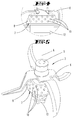
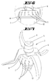
- FIGS. 2 to 7 illustrated embodiments of an agitator 2 have a bearing body 7, which comes into contact with the liquid to be mixed in contact surface 8 three-dimensional structures 9,10,11, which interfere with the formation of a boundary layer.
- the surface structure has a plurality of spaced-apart three-dimensional structural elements / defects 9,10,11. Between the three-dimensional structural elements 9,10,11, the surface 8 is substantially smooth-walled.
- the three-dimensional structural elements 9 to 11 are in the FIGS. 2 to 7 exaggeratedly high and exaggeratedly sharp-edged.
- the three-dimensional structural elements 9, 10, 11 form an uneven, but still smooth-walled surface design in that they merge without kinking into the truncated cone surface 8 of the bearing body 7 to form curves. As a result, the surface 8 of the bearing body retains good cleanability.
- the three-dimensional structures 9,10,11 laminar flow boundary layer on the three-dimensional structures 9 to 11 detaches. There are turbulences, which lead to a better mixing of the mix.
- the three-dimensional structures may be grooves / grooves 9. But it can also island-like depressions 10, dents or elevations 11 but be.
- the three-dimensional structures 9, 10, 11 can thus be concavities or bulges from the otherwise smooth surface 8 of the bearing body 7.
- the three-dimensional structures 9,10,11 can vary in height, so that a flow is redirected again and again. Solids are flushed from surface 8 before forming larger surface contaminants with other solids. It forms a turbulent flow, which leads to a better mixing of the mix.
- grooves / grooves 9 are formed, which extend along generatrices of the truncated cone lateral surface.
- the grooves / grooves 9 are directed to the imaginary tip of the truncated cone, which lies in the axis of rotation A of the agitator shaft 5.
- the grooves / grooves 9 are at a distance from the bottom 3 remote from the end face of the bearing body 7. Their distance from the large diameter edge of the bearing body 7 varies in the circumferential direction of the bearing body 7.
- the three-dimensional structures 9 are about 0.5 to 1.5 cm apart from each other so that they form downstream of the three-dimensional structures 9 turbulent vortex zones in the liquid flow.
- the depth of the grooves / grooves 9 may be between 1 and 3 mm.
- the transitions of the grooves in the truncated cone lateral surface 8 can - as shown in the drawings - be sharp-edged. However, it is preferably provided that the transitions are rounded.
- the indentations 10 have an approximately circular floor plan and a diameter between 0.3 and 1 cm.
- the indentations 10 go over the formation of a bending line in the truncated cone lateral surface 8. Again, it is preferably provided that the transition from the indentations 10 in the truncated cone lateral surface 8 is rounded.
- the surface structural elements can also be isolated bulges.
- the bulges may have a circular outline. But they can also be formed by ribs, as in the in the FIGS. 6 and 7 illustrated third embodiment are realized.
- the ribs extend here over the entire height of the frustoconical surface portion 8 and along each of a generatrix.
- the width of each rib 11 is smaller in the circumferential direction than the distance between two adjacent ribs 11.
- the ribs 11 are formed in a truncated pyramid or prismatic.
- the substantially flat side surfaces of the ribs 11 merge into the truncated cone lateral surface 8 or in the top surfaces of the ribs 11, forming kink lines.
- the side surfaces of the ribs rounded into the apex surface and the truncated cone lateral surface 8 pass over.
- the three-dimensional structures 9, 10, 11 each show the formation of curves from the otherwise smooth-walled surface 8. They are formed either as indentations 9, 10 or as bulges 11.
- the three-dimensional structures preferably have only rounded surface sections, so that an easily cleaned bearing body surface is formed.
- the three-dimensional structures are formed to form edges.
- the three-dimensional structures may have a polygonal floor plan on their vaulted or bulged sections. This promotes the formation of eddy zones.
Landscapes
- Engineering & Computer Science (AREA)
- Mechanical Engineering (AREA)
- Food Science & Technology (AREA)
- Mixers Of The Rotary Stirring Type (AREA)
- Food-Manufacturing Devices (AREA)
Abstract
Description
- Die Erfindung betrifft einen Rührtopf mit einem einen insbesondere am Boden des Rührtopfes angeordneten Rührwerk, das einen drehfest insbesondere dem Boden zugeordneten Lagerkörper zur Lagerung einer Rührwelle zum Drehantreiben eines insbesondere einen Messersatz aufweisenden Rührkörpers zur Ausbildung einer Zirkulationsströmung einer sich im Rührtopf befindenden Flüssigkeit aufweist.
- Ein gattungsgemäßer Rührtopf ist u.a. aus der
DE 10 2012101 775 A1 bekannt. Der bekannte Rührtopf ist lösbarer Teil einer Küchenmaschine und besitzt eine von einem Deckel verschließbare Einfüllöffnung, einen sich an die Einfüllöffnung anschließenden, eine rotationssymmetrisch ausgebildete Wandung und einen der Einfüllöffnung gegenüberliegenden, ebenen Boden, der eine Öffnung hat, in der ein Rührwerk eingesteckt ist. Das Rührwerk besitzt einen Lagerkörper, der sich unter Zwischenlage einer Dichtung auf dem Boden des Rührtopfes abstützt und eine Rührwelle lagert, die von der Unterseite des Bodens abragt und von einem Antrieb in Drehung versetzt werden kann. Im Inneren des Rührtopfes ist die Rührwelle mit einem Rührkörper verbunden, der von zwei sich kreuzenden Messersätzen ausgebildet ist. Der Rührkörper hat eine glattwandige, insbesondere aus Metall bestehende Oberfläche, die eine Kegelstumpf-Mantelfläche ist. Glattwandige Flächen haben den Vorteil, sich gut zum Reinigen zu eignen. Wird das Rührwerk in Drehung versetzt, so bildet sich um den Lagerkörper eine Zirkulationsströmung aus, deren Hauptrichtung eine Kreisrichtung um die Drehachse des Rührkörpers ist. An der glattwandigen Oberfläche des Lagerkörpers bildet sich eine hydrodynamische laminare Grenzschicht aus. Für eine gute Durchmischung der sich im Rührtopf befindenden Flüssigkeit sind solche stationären Grenzschichten von Nachteil, da ein Massentransport quer zum Verlauf der Grenzschicht im Wesentlichen diffusionskontrolliert ist. - Der Erfindung liegt die Aufgabe zugrunde, die Durchmischung der Flüssigkeit in der Nähe des Lagerkörpers zu verbessern.
- Gelöst wird die Aufgabe durch die in den Ansprüchen angegebene Erfindung, wobei zunächst und im Wesentlichen vorgesehen ist, dass eine mit der Flüssigkeit in Berührung stehende Oberfläche des Lagerkörpers eine die Ausbildung einer Strömungsgrenzschicht störende Oberflächenstruktur aufweist. Die Oberflächenstruktur besitzt voneinander beabstandete Oberflächenstrukturelemente, so dass sich eine Grenzschicht ablösende Oberflächenstruktur ausbildet. Die Oberflächenstrukturelemente bestehen im Wesentlichen aus Einwölbungen beziehungsweise aus Auswölbungen. Die Einwölbungen beziehungsweise Auswölbungen können einen langgestreckten Grundriss aufweisen. Sie können beispielsweise von Nuten oder Rippen gebildet sein. Die Nuten bilden lokale Vertiefungen. Die Rippen bilden lokale Erhöhungen. Es ist von Vorteil, wenn die Einwölbungen oder Auswölbungen vereinzelt, d.h. voneinander beabstandet auf der ansonsten glatten Oberfläche des Lagerkörpers angeordnet sind. Es ist ferner von Vorteil, wenn die Einwölbungen oder Auswölbungen knickfrei in die ansonsten glatt verlaufende Oberfläche übergehen. Die Einwölbungen oder Auswölbungen können aber mit einer Übergangskante in die glattwandige Oberfläche übergehen. Die Oberfläche ist vorzugsweise eine Kegelstumpf-Mantelfläche. Auf der Kegelstumpf-Mantelfläche können Rippen oder Nuten verlaufen, die sich in Richtung der Mantellinie erstrecken, also auf eine gedachte Kegelspitze zugerichtet sind. Es ist aber auch möglich, gleichmäßig oder ungleichmäßig verteilte Vertiefungen oder Erhöhungen auf der Oberfläche des Lagerkörpers anzuordnen. Es handelt sich um dreidimensionale Strukturen, deren Höhe nur 1 bis 3 mm betragen brauchen, um eine sich ansonsten an der Oberfläche des Lagerkörpers ausbildende Strömungsgrenzschicht zu zerstören. Die dreidimensionalen Oberflächenstrukturen in der ansonsten glatten Oberfläche bilden lokale Störungen einer Strömung entlang der Oberfläche aus. Eine sich eventuell zwischen den einzelnen Störungen ausbildende laminare Grenzschicht löst sich an den Störungen ab. Stromabwärts der dreidimensionalen Strukturen bilden sich Wirbel aus. Die so ausgebildete Grenzschichtablösung sorgt für eine bessere Durchmischung der sich im Rührtopf befindenden Flüssigkeit im Bereich der Oberfläche des Lagerkörpers. Im Bereich der Wirbelzonen, die sich zwischen den einzelnen dreidimensionalen Strukturen ausbilden, findet ein konvektiver Massenstransport statt.
- Ausführungsbeispiele werden nachfolgend anhand beigefügter Zeichnungen erläutert. Es zeigen:
- Fig. 1
- eine Übersichtsdarstellung einer einen Rührtopf 1 aufweisenden Küchenmaschine,
- Fig. 2
- vergrößert den Ausschnitt II-II als Ansicht auf einen Lagerkörper 7 eines ersten Ausführungsbeispiels,
- Fig. 3
- den Lagerkörper mit Rührkörper des ersten Ausführungsbeispiels in einer perspektivischen Darstellung, wobei die Nuten der besseren Sichtbarkeit halber übertrieben tief und scharfkantig dargestellt sind,
- Fig. 4
- eine Darstellung gemäß
Figur 2 eines zweiten Ausführungsbeispiels, - Fig. 5
- eine perspektivische Darstellung des zweiten Ausführungsbeispiels, wobei die Vertiefungen der besseren Sichtbarkeit halber übertrieben tief und scharfkantig dargestellt sind,
- Fig. 6
- eine Darstellung gemäß
Fig. 2 eines dritten Ausführungsbeispiels, wobei die Rippen der besseren Sichtbarkeit halber übertrieben hoch und scharfkantig dargestellt sind, und - Fig. 7
- eine perspektivische Darstellung des dritten Ausführungsbeispiels.
- Die
Figur 1 zeigt ein Küchengerät mit einem Gestell, welches einen Rührtopf 1 trägt. Der Rührtopf 1 besitzt eine Einfüllöffnung und einen der Einfüllöffnung gegenüberliegenden Boden 3. Der Boden 3 besitzt eine Durchgriffsöffnung, durch die ein Kupplungsfortsatz 12 bis über die Unterseite des Bodens ragt. Der Kupplungsfortsatz 12 steckt lösbar in einer Antriebskupplung, mit der der Kupplungsfortsatz 12 und eine fest mit dem Kupplungsfortsatz 12 verbundene Rührwelle 5 in eine Drehung gebracht werden kann. Der hierzu verwendete Antriebsmotor 4 steckt im Gerätegehäuse. - An ihrem freien, in den Rührtopf 1 ragenden Ende trägt die Rührwelle 5 einen Rührkörper, der im Ausführungsbeispiel von einem Messersatz mit zwei sich kreuzenden Messerarmen ausgebildet ist. Die Rührwelle 5 ist in einem Lagerkörper 7 gelagert, der sich auf dem Boden 3 abstützt. Er besitzt eine metallische Oberfläche 8. Der Lagerkörper 7 kann zusammen mit der Rührwelle 5 und dem Messersatz aus der Durchgriffsöffnung des Bodens 3 herausgenommen werden.
- Eine Drehung der Rührwelle 5 beziehungsweise des Rührkörpers 6 versetzt eine sich im Rührtopf 1 befindende Flüssigkeit in Bewegung. Es bildet sich eine Zirkularströmung entlang der Innenwände des Rührtopfes 1 und entlang der kegelstumpfförmigen Oberfläche 8 des Lagerkörpers 7 aus.
- Der Lagerkörper 7 besitzt einen Durchmesser von etwa 4 bis 5 cm und eine Höhe von 1 bis 2 cm. Beim Stand der Technik ist die auf einer Konusfläche verlaufende Oberfläche 8 des Lagerkörpers 7 glattwandig gestaltet. Dies hat zur Folge, dass die Zirkularströmung um die Drehachse A der Rührwelle 5 eine Strömungsgrenzschicht in einem Bereich unmittelbar oberhalb der Oberfläche 8 des Lagerkörpers 7 ausbildet.
- Die in den
Figuren 2 bis 7 dargestellten Ausführungsbeispiele eines Rührwerks 2 besitzen einen Lagerkörper 7, dessen mit der zu durchmischenden Flüssigkeit in Berührung tretende Oberfläche 8 dreidimensionale Strukturen 9,10,11 aufweist, die die Ausbildung einer Grenzschicht stören. Die Oberflächenstruktur besitzt eine Vielzahl von voneinander beabstandeten dreidimensionalen Strukturelemente/Störstellen 9,10,11. Zwischen den dreidimensionalen Strukturelemente 9,10,11 verläuft die Oberfläche 8 im Wesentlichen glattwandig. - Die dreidimensionalen Strukturelemente 9 bis 11 sind in den
Figuren 2 bis 7 übertrieben hoch und übertrieben scharfkantig dargestellt. In ihrer bevorzugten Ausgestaltung bilden die dreidimensionalen Strukturelemente 9,10,11 eine zwar unebene, aber immer noch glattwandige Oberflächengestaltung, indem sie unter Ausbildung von Rundungen knickfrei in die Kegelstumpf-Oberfläche 8 des Lagerkörpers 7 übergehen. Hierdurch behält die Oberfläche 8 des Lagerkörpers eine gute Reinigbarkeit. - Durch die nicht ebene Oberflächenkontur können Verwirbelungen entstehen, so dass sich eine zwischen den dreidimensionalen Strukturen 9,10,11 ausbildende laminare Strömungsgrenzschicht an den dreidimensionale Strukturen 9 bis 11 ablöst. Es entstehen Verwirbelungen, die zu einer besseren Durchmischung des Mixgutes führen. Anders als beim Stand der Technik bildet sich keine einfache, an der Oberfläche 8 anliegende Strömung rundum den Lagerkörper 7 aus, bei der sich nahe der Oberfläche eine stationäre Strömungsgrenzschicht ausbildet. Die dreidimensionalen Strukturen können Nuten/Rillen 9 sein. Es können aber auch inselartige Vertiefungen 10, Dellen oder aber auch Erhöhungen 11 sein. Die dreidimensionale Strukturen 9,10,11 können somit Einwölbungen oder Auswölbungen aus der ansonsten glatten Oberfläche 8 des Lagerkörpers 7 sein. Die dreidimensionale Strukturen 9,10,11 können in der Höhe variieren, so dass eine Strömung immer wieder umgelenkt wird. Feststoffe werden von der Oberfläche 8 gespült, bevor sie mit anderen Feststoffen zusammen größere Oberflächenverunreinigungen bilden. Es bildet sich eine turbulente Strömung aus, was zu einer besseren Durchmischung des Mixgutes führt.
- Bei dem in den
Figuren 2 und3 dargestellten Ausführungsbeispiel werden die eine Ausbildung einer Grenzschicht störenden Oberflächenstrukturen von Nuten/Rillen 9 ausgebildet, die sich entlang von Mantellinien der Kegelstumpf-Mantelfläche erstrecken. Die Nuten/Rillen 9 sind auf die gedachte Spitze des Kegelstumpfes gerichtet, der in der Drehachse A der Rührwelle 5 liegt. Es wechseln sich Nuten/Rillen 9 mit einer unterschiedlichen Länge ab. Die Nuten/Rillen 9 haben aber einen Abstand zu der vom Boden 3 entfernt liegenden Stirnseite des Lagerkörpers 7. Ihr Abstand zu der durchmessergroßen Randkante des Lagerkörpers 7 variiert in Umfangsrichtung des Lagerkörpers 7. Die dreidimensionalen Strukturen 9 sind etwa 0,5 bis 1,5 cm voneinander beabstandet, so dass sie stromabwärts der dreidimensionalen Strukturen 9 turbulente Wirbelzonen in der Flüssigkeitsströmung ausbilden. Die Tiefe der Nuten/Rillen 9 kann zwischen 1 und 3 mm betragen. Die Übergänge der Nuten in die Kegelstumpf-Mantelfläche 8 kann - wie in den Zeichnungen dargestellt - scharfkantig sein. Es ist aber bevorzugt vorgesehen, dass die Übergänge gerundet verlaufen. - Bei dem in den
Figuren 4 und 5 dargestellten zweiten Ausführungsbeispiel bestehen die dreidimensionalen, die Ausbildung einer Grenzschicht störenden Oberflächen-Strukturelemente aus einzelnen Vertiefungen/Einwölbungen 10. Im Ausführungsbeispiel haben die Einwölbungen 10 einen etwa kreisförmigen Grundriss und einen Durchmesser zwischen 0,3 und 1 cm. Die Einwölbungen 10 gehen unter Ausbildung einer Knicklinie in die Kegelstumpf-Mantelfläche 8 über. Auch hier ist bevorzugt vorgesehen, dass der Übergang von den Einwölbungen 10 in die Kegelstumpf-Mantelfläche 8 gerundet ist. - Anstelle von Einwölbungen 10 können die Oberflächen-Strukturelemente aber auch vereinzelte Auswölbungen sein. Die Auswölbungen können einen kreisförmigen Grundriss aufweisen. Sie können aber auch von Rippen ausgebildet werden, wie sie in den in den
Figuren 6 und 7 dargestellten dritten Ausführungsbeispiel verwirklicht sind. Die Rippen erstrecken sich hier über die gesamte Höhe des kegelstumpfförmigen Oberflächenabschnittes 8 und entlang jeweils einer Mantellinie. Die Breite jeder Rippe 11 ist in Umfangsrichtung geringer als der Abstand zweier benachbarter Rippen 11. Die Rippen 11 sind pyramidenstumpfartig beziehungsweise prismatisch ausgebildet. Die im Wesentlichen ebenen Seitenflächen der Rippen 11 gehen unter Ausbildung von Knicklinien in die Kegelstumpf-Mantelfläche 8 beziehungsweise in Scheitelflächen der Rippen 11 über. Es ist bevorzugt vorgesehen, dass die Seitenflächen der Rippen gerundet in die Scheitelfläche und die Kegelstumpf-Mantelfläche 8 übergehen. Bei in den in den Zeichnungen nicht dargestellten Ausführungsbeispielen gehen die dreidimensionalen Strukturen 9, 10, 11 jeweils unter Ausbildung von Rundungen aus der ansonsten glattwandigen Oberfläche 8 hervor. Sie sind entweder als Einwölbungen 9, 10 oder als Auswölbungen 11 ausgebildet. Bevorzugt haben die dreidimensionalen Strukturen nur gerundete Oberflächenabschnitte, damit sich eine leicht zu reinigende Lagerkörper-Oberfläche ausbildet. - Es ist aber auch vorgesehen, dass die dreidimensionalen Strukturen unter Ausbildung von Kanten gebildet sind. So können die dreidimensionalen Strukturen beispielsweise einen polygonartigen Grundriss auf ihren eingewölbten oder ausgewölbten Abschnitten Kanten aufweisen. Dies fördert die Ausbildung von Wirbelzonen.
- Die vorstehenden Ausführungen dienen der Erläuterung der von der Anmeldung insgesamt erfassten Erfindungen, die den Stand der Technik zumindest durch die folgenden Merkmalskombinationen jeweils eigenständig weiterbilden, nämlich:
- Eine Vorrichtung, die dadurch gekennzeichnet ist, dass eine mit der Flüssigkeit in Berührung stehende Oberfläche 8 des Lagerkörpers 7 eine die Ausbildung einer laminaren Grenzschicht störende Oberflächenstruktur 9,10,11 aufweist;
- Eine Vorrichtung, die dadurch gekennzeichnet ist, dass die die Ausbildung einer laminaren Grenzschicht störende Oberflächenstruktur eine Mehrzahl von einander in Strömungsrichtung beabstandet angeordnete Oberflächen-Strukturelemente, insbesondere Einwölbungen 9,10 oder Auswölbungen 11 in einer ansonsten glatten Oberfläche 8 aufweist;
- Eine Vorrichtung, die dadurch gekennzeichnet ist, dass die Oberflächen-Strukturelemente 9,10 knickfrei, insbesondere gerundet oder unter Ausbildung einer Kante in die Oberfläche 8 des Lagerkörpers 7 übergeht;
- Eine Vorrichtung, die dadurch gekennzeichnet ist, dass die Oberfläche 8 eine Kegelstumpf-Mantelfläche um die Drehachse A der Rührwelle 5 ist;
- Eine Vorrichtung, die dadurch gekennzeichnet ist, dass die Einwölbungen von in Richtung von Mantellinien der Kegelstumpf-Mantelfläche verlaufenden Nuten 9 und/ oder dass die Auswölbungen von in Richtung der Mantellinie der Kegelstumpf-Mantelfläche verlaufenden Rippen 11 gebildet sind;
- Eine Vorrichtung, die dadurch gekennzeichnet ist, dass die Vertiefungen 10 und/oder die Auswölbungen 11 einen ovalen oder kreisförmigen Grundriss aufweisen;
- Eine Vorrichtung, die dadurch gekennzeichnet ist, dass die Vertiefungen 10 und/oder die Auswölbungen 11 einen ovalen oder kreisförmigen Grundriss aufweisen;
- Eine Vorrichtung, die dadurch gekennzeichnet ist, dass die Oberflächenstrukturen 9,10,11 im Wesentlichen gleichmäßig über die Umfangsfläche des Lagerkörpers 7 verteilt angeordnet sind;
- Eine Vorrichtung, die dadurch gekennzeichnet ist, dass die Oberfläche 8 des Lagerkörpers 7 eine die Ausbildung einer Grenzschicht störende Oberflächenstruktur 9,10,11 aufweist;
- Vorrichtung, gekennzeichnet durch Oberflächenstrukturelemente 9,10,11 gemäß einem der Ansprüche 2 bis 7.
-
- 1
- Rührtopf
- 2
- Rührwerk
- 3
- Boden
- 4
- Antriebsmotor
- 5
- Rührwelle
- 6
- Rührkörper
- 7
- Lagerkörper
- 8
- Oberfläche
- 9
- Nuten/ Rillen, Einwölbung
- 10
- Einwölbung
- 11
- Auswölbung, Rippe
- 12
- Kupplungsfortsatz
- A
- Drehachse
Claims (12)
- Rührtopf (1) mit einem an einer Wandung (3) des Rührtopfes (1) angeordneten Rührwerk (2), das einen drehfest an der Wandung (3) zugeordneten Lagerkörper (7) zur Lagerung einer Rührwelle (5) zum Drehantreiben eines insbesondere einen Messersatz aufweisenden Rührkörpers (6) zur Ausbildung einer Zirkulationsströmung einer sich im Rührtopf (1) befindenden Flüssigkeit aufweist, dadurch gekennzeichnet, dass eine mit der Flüssigkeit in Berührung stehende Oberfläche (8) des Lagerkörpers (7) eine die Ausbildung einer laminaren Grenzschicht störende Oberflächenstruktur (9,10,11) aufweist.
- Rührtopf nach Anspruch 1, dadurch gekennzeichnet, dass die die Ausbildung einer laminaren Grenzschicht störende Oberflächenstruktur eine Mehrzahl von einander in Strömungsrichtung beabstandet angeordnete Oberflächen-Strukturelemente an einer ansonsten glatten Oberfläche (8) aufweist.
- Rührtopf nach Anspruch 2, dadurch gekennzeichnet, dass die Oberflächen-Strukturelemente Einwölbungen (9,10) oder Auswölbungen (11) sind.
- Rührtopf nach einem der vorhergehenden Ansprüche, dadurch gekennzeichnet, dass die Oberflächen-Strukturelemente (9,19) knickfrei in die Oberfläche (8) des Lagerkörpers (7) übergehen.
- Rührtopf nach Anspruch 4, dadurch gekennzeichnet, dass die Oberflächen-Strukturelemente (9,19) gerundet oder unter Ausbildung einer Kante in die Oberfläche (8) des Lagerkörpers (7) übergehen.
- Rührtopf nach einem der vorhergehenden Ansprüche, dadurch gekennzeichnet, dass die Oberfläche (8) eine Kegelstumpf-Mantelfläche um die Drehachse (A) der Rührwelle (5) ist.
- Rührtopf nach einem der Ansprüche 3 bis 6, dadurch gekennzeichnet, dass die Einwölbungen von in Richtung von Mantellinien der Kegelstumpf-Mantelfläche verlaufenden Nuten (9) gebildet sind.
- Rührtopf nach einem der Ansprüche 3 bis 7, dadurch gekennzeichnet, dass die Auswölbungen von in Richtung der Mantellinie der Kegelstumpf-Mantelfläche verlaufenden Rippen (11) gebildet sind.
- Rührtopf nach einem der Ansprüche 3 bis 8, dadurch gekennzeichnet, dass die Einwölbungen (10) und/oder die Auswölbungen (11) einen ovalen oder kreisförmigen Grundriss aufweisen.
- Rührtopf nach einem der vorhergehenden Ansprüche, dadurch gekennzeichnet, dass die Oberflächenstrukturen (9,10,11) im Wesentlichen gleichmäßig über die Umfangsfläche des Lagerkörpers (7) verteilt angeordnet sind.
- Rührkörper (6) zur Verwendung an einem Rührtopf (1) mit einem eine Rührwelle (5) lagernden Lagerkörper (7), wobei die Rührwelle (5) einen insbesondere einen Messersatz aufweisenden Rührkörper (6) zur Ausbildung einer Zirkularströmung um den Lagerkörper (7) trägt, dadurch gekennzeichnet, dass die Oberfläche (8) des Lagerkörpers (7) eine die Ausbildung einer Grenzschicht störende Oberflächenstruktur (9,10,11) aufweist.
- Rührkörper nach Anspruch 8, gekennzeichnet durch Oberflächenstrukturelemente (9, 10, 11) gemäß einem der Ansprüche 2 bis 7.
Priority Applications (1)
| Application Number | Priority Date | Filing Date | Title |
|---|---|---|---|
| PL14193038T PL2878247T3 (pl) | 2013-11-28 | 2014-11-13 | Naczynie mieszające z mieszadłem zawierającym korpus łożyskowy ze strukturą powierzchni usuwającą warstwę graniczną |
Applications Claiming Priority (1)
| Application Number | Priority Date | Filing Date | Title |
|---|---|---|---|
| DE102013113153.0A DE102013113153A1 (de) | 2013-11-28 | 2013-11-28 | Rührtopf mit einem einen Grenzschicht ablösend oberflächenstrukturierten Lagerkörper aufweisenden Rührwerk |
Publications (2)
| Publication Number | Publication Date |
|---|---|
| EP2878247A1 true EP2878247A1 (de) | 2015-06-03 |
| EP2878247B1 EP2878247B1 (de) | 2020-05-06 |
Family
ID=51893914
Family Applications (1)
| Application Number | Title | Priority Date | Filing Date |
|---|---|---|---|
| EP14193038.8A Active EP2878247B1 (de) | 2013-11-28 | 2014-11-13 | Rührtopf mit einem einen Grenzschicht ablösend oberflächenstrukturierten Lagerkörper aufweisenden Rührwerk |
Country Status (6)
| Country | Link |
|---|---|
| EP (1) | EP2878247B1 (de) |
| CN (1) | CN104665635B (de) |
| DE (1) | DE102013113153A1 (de) |
| ES (1) | ES2798304T3 (de) |
| PL (1) | PL2878247T3 (de) |
| PT (1) | PT2878247T (de) |
Families Citing this family (1)
| Publication number | Priority date | Publication date | Assignee | Title |
|---|---|---|---|---|
| DE102018119811A1 (de) | 2017-12-05 | 2019-06-06 | Vorwerk & Co. Interholding Gmbh | Rührwerklager für eine elektromotorisch betriebene Küchenmaschine |
Citations (2)
| Publication number | Priority date | Publication date | Assignee | Title |
|---|---|---|---|---|
| US2794627A (en) * | 1954-10-21 | 1957-06-04 | Silex Co | Blender |
| DE102012101775A1 (de) | 2012-03-02 | 2013-09-05 | Vorwerk & Co. Interholding Gmbh | Küchenmaschine mit einem Gargefäß sowie Verfahren zum Betreiben einer Küchenmaschine |
Family Cites Families (5)
| Publication number | Priority date | Publication date | Assignee | Title |
|---|---|---|---|---|
| US4722608A (en) * | 1985-07-30 | 1988-02-02 | General Signal Corp. | Mixing apparatus |
| US7350963B2 (en) * | 2005-02-04 | 2008-04-01 | Hamilton Beach Brands, Inc. | Blender jar |
| CN2922737Y (zh) * | 2006-06-12 | 2007-07-18 | 杨文焌 | 泡沫混合机的旋转式搅拌刀具 |
| CN201701085U (zh) * | 2010-04-16 | 2011-01-12 | 陈明松 | 一种食物搅拌组件 |
| CN202027447U (zh) * | 2011-04-20 | 2011-11-09 | 广州市拓璞电器发展有限公司 | 一种带干扰液体环流附件的打奶机 |
-
2013
- 2013-11-28 DE DE102013113153.0A patent/DE102013113153A1/de not_active Withdrawn
-
2014
- 2014-11-13 PL PL14193038T patent/PL2878247T3/pl unknown
- 2014-11-13 PT PT141930388T patent/PT2878247T/pt unknown
- 2014-11-13 EP EP14193038.8A patent/EP2878247B1/de active Active
- 2014-11-13 ES ES14193038T patent/ES2798304T3/es active Active
- 2014-11-28 CN CN201410858329.1A patent/CN104665635B/zh not_active Expired - Fee Related
Patent Citations (2)
| Publication number | Priority date | Publication date | Assignee | Title |
|---|---|---|---|---|
| US2794627A (en) * | 1954-10-21 | 1957-06-04 | Silex Co | Blender |
| DE102012101775A1 (de) | 2012-03-02 | 2013-09-05 | Vorwerk & Co. Interholding Gmbh | Küchenmaschine mit einem Gargefäß sowie Verfahren zum Betreiben einer Küchenmaschine |
Also Published As
| Publication number | Publication date |
|---|---|
| EP2878247B1 (de) | 2020-05-06 |
| DE102013113153A1 (de) | 2015-05-28 |
| CN104665635A (zh) | 2015-06-03 |
| PL2878247T3 (pl) | 2020-11-02 |
| ES2798304T3 (es) | 2020-12-10 |
| CN104665635B (zh) | 2018-10-19 |
| PT2878247T (pt) | 2020-06-17 |
Similar Documents
| Publication | Publication Date | Title |
|---|---|---|
| DE102011051149B4 (de) | Elektrisch betriebene Küchenmaschine mit einem Gargefäß | |
| DE69102532T2 (de) | Bodenentwässerung. | |
| EP1065963B1 (de) | Glockenförmige abschirmung für die verwendung in einem haushaltsgerät, insbesondere stabmixer oder handrührer | |
| DE202018006433U1 (de) | Einlasskanüle für eine Fluidpumpe | |
| EP3501269B1 (de) | Pressdeckel | |
| DE212011100196U1 (de) | Mischgefäß | |
| CH652070A5 (de) | Vorrichtung zum mischen und entgasen von komponenten von kunstharzen. | |
| EP3513696B1 (de) | Küchenmaschine mit einem abdeckelement für ein zubereitunsgefäss | |
| CH705943A1 (de) | Duschwanne mit einer geneigten Bodenfläche. | |
| DE102014111216B4 (de) | Abdeckteil zum teilweisen Verschließen einer Durchgangsöffnung eines Gefäßdeckels eines Küchengerätes | |
| EP0056610B1 (de) | Liegender Behälter zur Behandlung von Weinmaische | |
| DE2643560C2 (de) | Rührvorrichtung | |
| EP2878247B1 (de) | Rührtopf mit einem einen Grenzschicht ablösend oberflächenstrukturierten Lagerkörper aufweisenden Rührwerk | |
| AT16295U1 (de) | Pulperrotor und Pulper | |
| CH690835A5 (de) | Rührwerk zum Anregen einer Güllen-Zirkulation in einem Güllenkasten. | |
| WO2004030498A2 (de) | Schlagscheibe für küchengeräte | |
| DE102006042990B3 (de) | Passiergerät | |
| DE3334637C2 (de) | ||
| DE8121849U1 (de) | Abgabevorrichtung fuer hohlgefaesse | |
| DE19725698A1 (de) | Schöpfzeug und Adhäsionsheber | |
| DE102017221138B4 (de) | Rührgefäß für einen Stabmixer, Einsatzelement für ein Rührgefäß und Küchenrührvorrichtung | |
| EP2989947A1 (de) | Abdeckelement für ein verriegelungselement einer küchenmaschine | |
| EP1463429B1 (de) | Kochgeschirr | |
| DE3043540C2 (de) | Stehender Behälter für Traubenmaische | |
| DE102020129150B3 (de) | Topfförmiger Einsatz |
Legal Events
| Date | Code | Title | Description |
|---|---|---|---|
| PUAI | Public reference made under article 153(3) epc to a published international application that has entered the european phase |
Free format text: ORIGINAL CODE: 0009012 |
|
| 17P | Request for examination filed |
Effective date: 20141113 |
|
| AK | Designated contracting states |
Kind code of ref document: A1 Designated state(s): AL AT BE BG CH CY CZ DE DK EE ES FI FR GB GR HR HU IE IS IT LI LT LU LV MC MK MT NL NO PL PT RO RS SE SI SK SM TR |
|
| AX | Request for extension of the european patent |
Extension state: BA ME |
|
| R17P | Request for examination filed (corrected) |
Effective date: 20150929 |
|
| RBV | Designated contracting states (corrected) |
Designated state(s): AL AT BE BG CH CY CZ DE DK EE ES FI FR GB GR HR HU IE IS IT LI LT LU LV MC MK MT NL NO PL PT RO RS SE SI SK SM TR |
|
| STAA | Information on the status of an ep patent application or granted ep patent |
Free format text: STATUS: EXAMINATION IS IN PROGRESS |
|
| 17Q | First examination report despatched |
Effective date: 20180130 |
|
| GRAP | Despatch of communication of intention to grant a patent |
Free format text: ORIGINAL CODE: EPIDOSNIGR1 |
|
| STAA | Information on the status of an ep patent application or granted ep patent |
Free format text: STATUS: GRANT OF PATENT IS INTENDED |
|
| INTG | Intention to grant announced |
Effective date: 20191210 |
|
| GRAS | Grant fee paid |
Free format text: ORIGINAL CODE: EPIDOSNIGR3 |
|
| GRAA | (expected) grant |
Free format text: ORIGINAL CODE: 0009210 |
|
| STAA | Information on the status of an ep patent application or granted ep patent |
Free format text: STATUS: THE PATENT HAS BEEN GRANTED |
|
| AK | Designated contracting states |
Kind code of ref document: B1 Designated state(s): AL AT BE BG CH CY CZ DE DK EE ES FI FR GB GR HR HU IE IS IT LI LT LU LV MC MK MT NL NO PL PT RO RS SE SI SK SM TR |
|
| REG | Reference to a national code |
Ref country code: GB Ref legal event code: FG4D Free format text: NOT ENGLISH |
|
| REG | Reference to a national code |
Ref country code: CH Ref legal event code: EP Ref country code: AT Ref legal event code: REF Ref document number: 1265426 Country of ref document: AT Kind code of ref document: T Effective date: 20200515 |
|
| REG | Reference to a national code |
Ref country code: IE Ref legal event code: FG4D Free format text: LANGUAGE OF EP DOCUMENT: GERMAN |
|
| REG | Reference to a national code |
Ref country code: DE Ref legal event code: R096 Ref document number: 502014014123 Country of ref document: DE |
|
| REG | Reference to a national code |
Ref country code: PT Ref legal event code: SC4A Ref document number: 2878247 Country of ref document: PT Date of ref document: 20200617 Kind code of ref document: T Free format text: AVAILABILITY OF NATIONAL TRANSLATION Effective date: 20200608 |
|
| REG | Reference to a national code |
Ref country code: LT Ref legal event code: MG4D |
|
| REG | Reference to a national code |
Ref country code: NL Ref legal event code: MP Effective date: 20200506 |
|
| PG25 | Lapsed in a contracting state [announced via postgrant information from national office to epo] |
Ref country code: LT Free format text: LAPSE BECAUSE OF FAILURE TO SUBMIT A TRANSLATION OF THE DESCRIPTION OR TO PAY THE FEE WITHIN THE PRESCRIBED TIME-LIMIT Effective date: 20200506 Ref country code: GR Free format text: LAPSE BECAUSE OF FAILURE TO SUBMIT A TRANSLATION OF THE DESCRIPTION OR TO PAY THE FEE WITHIN THE PRESCRIBED TIME-LIMIT Effective date: 20200807 Ref country code: NO Free format text: LAPSE BECAUSE OF FAILURE TO SUBMIT A TRANSLATION OF THE DESCRIPTION OR TO PAY THE FEE WITHIN THE PRESCRIBED TIME-LIMIT Effective date: 20200806 Ref country code: IS Free format text: LAPSE BECAUSE OF FAILURE TO SUBMIT A TRANSLATION OF THE DESCRIPTION OR TO PAY THE FEE WITHIN THE PRESCRIBED TIME-LIMIT Effective date: 20200906 Ref country code: SE Free format text: LAPSE BECAUSE OF FAILURE TO SUBMIT A TRANSLATION OF THE DESCRIPTION OR TO PAY THE FEE WITHIN THE PRESCRIBED TIME-LIMIT Effective date: 20200506 Ref country code: FI Free format text: LAPSE BECAUSE OF FAILURE TO SUBMIT A TRANSLATION OF THE DESCRIPTION OR TO PAY THE FEE WITHIN THE PRESCRIBED TIME-LIMIT Effective date: 20200506 |
|
| PG25 | Lapsed in a contracting state [announced via postgrant information from national office to epo] |
Ref country code: HR Free format text: LAPSE BECAUSE OF FAILURE TO SUBMIT A TRANSLATION OF THE DESCRIPTION OR TO PAY THE FEE WITHIN THE PRESCRIBED TIME-LIMIT Effective date: 20200506 Ref country code: RS Free format text: LAPSE BECAUSE OF FAILURE TO SUBMIT A TRANSLATION OF THE DESCRIPTION OR TO PAY THE FEE WITHIN THE PRESCRIBED TIME-LIMIT Effective date: 20200506 Ref country code: LV Free format text: LAPSE BECAUSE OF FAILURE TO SUBMIT A TRANSLATION OF THE DESCRIPTION OR TO PAY THE FEE WITHIN THE PRESCRIBED TIME-LIMIT Effective date: 20200506 Ref country code: BG Free format text: LAPSE BECAUSE OF FAILURE TO SUBMIT A TRANSLATION OF THE DESCRIPTION OR TO PAY THE FEE WITHIN THE PRESCRIBED TIME-LIMIT Effective date: 20200806 |
|
| REG | Reference to a national code |
Ref country code: ES Ref legal event code: FG2A Ref document number: 2798304 Country of ref document: ES Kind code of ref document: T3 Effective date: 20201210 |
|
| PG25 | Lapsed in a contracting state [announced via postgrant information from national office to epo] |
Ref country code: NL Free format text: LAPSE BECAUSE OF FAILURE TO SUBMIT A TRANSLATION OF THE DESCRIPTION OR TO PAY THE FEE WITHIN THE PRESCRIBED TIME-LIMIT Effective date: 20200506 Ref country code: AL Free format text: LAPSE BECAUSE OF FAILURE TO SUBMIT A TRANSLATION OF THE DESCRIPTION OR TO PAY THE FEE WITHIN THE PRESCRIBED TIME-LIMIT Effective date: 20200506 |
|
| PGFP | Annual fee paid to national office [announced via postgrant information from national office to epo] |
Ref country code: TR Payment date: 20201110 Year of fee payment: 7 |
|
| PG25 | Lapsed in a contracting state [announced via postgrant information from national office to epo] |
Ref country code: RO Free format text: LAPSE BECAUSE OF FAILURE TO SUBMIT A TRANSLATION OF THE DESCRIPTION OR TO PAY THE FEE WITHIN THE PRESCRIBED TIME-LIMIT Effective date: 20200506 Ref country code: SM Free format text: LAPSE BECAUSE OF FAILURE TO SUBMIT A TRANSLATION OF THE DESCRIPTION OR TO PAY THE FEE WITHIN THE PRESCRIBED TIME-LIMIT Effective date: 20200506 Ref country code: DK Free format text: LAPSE BECAUSE OF FAILURE TO SUBMIT A TRANSLATION OF THE DESCRIPTION OR TO PAY THE FEE WITHIN THE PRESCRIBED TIME-LIMIT Effective date: 20200506 Ref country code: EE Free format text: LAPSE BECAUSE OF FAILURE TO SUBMIT A TRANSLATION OF THE DESCRIPTION OR TO PAY THE FEE WITHIN THE PRESCRIBED TIME-LIMIT Effective date: 20200506 Ref country code: CZ Free format text: LAPSE BECAUSE OF FAILURE TO SUBMIT A TRANSLATION OF THE DESCRIPTION OR TO PAY THE FEE WITHIN THE PRESCRIBED TIME-LIMIT Effective date: 20200506 |
|
| REG | Reference to a national code |
Ref country code: DE Ref legal event code: R097 Ref document number: 502014014123 Country of ref document: DE |
|
| PG25 | Lapsed in a contracting state [announced via postgrant information from national office to epo] |
Ref country code: SK Free format text: LAPSE BECAUSE OF FAILURE TO SUBMIT A TRANSLATION OF THE DESCRIPTION OR TO PAY THE FEE WITHIN THE PRESCRIBED TIME-LIMIT Effective date: 20200506 |
|
| PLBE | No opposition filed within time limit |
Free format text: ORIGINAL CODE: 0009261 |
|
| STAA | Information on the status of an ep patent application or granted ep patent |
Free format text: STATUS: NO OPPOSITION FILED WITHIN TIME LIMIT |
|
| 26N | No opposition filed |
Effective date: 20210209 |
|
| PG25 | Lapsed in a contracting state [announced via postgrant information from national office to epo] |
Ref country code: SI Free format text: LAPSE BECAUSE OF FAILURE TO SUBMIT A TRANSLATION OF THE DESCRIPTION OR TO PAY THE FEE WITHIN THE PRESCRIBED TIME-LIMIT Effective date: 20200506 |
|
| PG25 | Lapsed in a contracting state [announced via postgrant information from national office to epo] |
Ref country code: MC Free format text: LAPSE BECAUSE OF FAILURE TO SUBMIT A TRANSLATION OF THE DESCRIPTION OR TO PAY THE FEE WITHIN THE PRESCRIBED TIME-LIMIT Effective date: 20200506 |
|
| REG | Reference to a national code |
Ref country code: CH Ref legal event code: PL |
|
| PG25 | Lapsed in a contracting state [announced via postgrant information from national office to epo] |
Ref country code: LU Free format text: LAPSE BECAUSE OF NON-PAYMENT OF DUE FEES Effective date: 20201113 |
|
| REG | Reference to a national code |
Ref country code: BE Ref legal event code: MM Effective date: 20201130 |
|
| PG25 | Lapsed in a contracting state [announced via postgrant information from national office to epo] |
Ref country code: LI Free format text: LAPSE BECAUSE OF NON-PAYMENT OF DUE FEES Effective date: 20201130 Ref country code: CH Free format text: LAPSE BECAUSE OF NON-PAYMENT OF DUE FEES Effective date: 20201130 |
|
| PG25 | Lapsed in a contracting state [announced via postgrant information from national office to epo] |
Ref country code: IE Free format text: LAPSE BECAUSE OF NON-PAYMENT OF DUE FEES Effective date: 20201113 |
|
| REG | Reference to a national code |
Ref country code: AT Ref legal event code: MM01 Ref document number: 1265426 Country of ref document: AT Kind code of ref document: T Effective date: 20201113 |
|
| PG25 | Lapsed in a contracting state [announced via postgrant information from national office to epo] |
Ref country code: AT Free format text: LAPSE BECAUSE OF NON-PAYMENT OF DUE FEES Effective date: 20201113 |
|
| PGFP | Annual fee paid to national office [announced via postgrant information from national office to epo] |
Ref country code: PT Payment date: 20211111 Year of fee payment: 8 Ref country code: GB Payment date: 20211123 Year of fee payment: 8 Ref country code: DE Payment date: 20211122 Year of fee payment: 8 Ref country code: FR Payment date: 20211119 Year of fee payment: 8 Ref country code: ES Payment date: 20211216 Year of fee payment: 8 |
|
| PGFP | Annual fee paid to national office [announced via postgrant information from national office to epo] |
Ref country code: IT Payment date: 20211130 Year of fee payment: 8 |
|
| PGFP | Annual fee paid to national office [announced via postgrant information from national office to epo] |
Ref country code: PL Payment date: 20211104 Year of fee payment: 8 |
|
| PG25 | Lapsed in a contracting state [announced via postgrant information from national office to epo] |
Ref country code: MT Free format text: LAPSE BECAUSE OF FAILURE TO SUBMIT A TRANSLATION OF THE DESCRIPTION OR TO PAY THE FEE WITHIN THE PRESCRIBED TIME-LIMIT Effective date: 20200506 Ref country code: CY Free format text: LAPSE BECAUSE OF FAILURE TO SUBMIT A TRANSLATION OF THE DESCRIPTION OR TO PAY THE FEE WITHIN THE PRESCRIBED TIME-LIMIT Effective date: 20200506 |
|
| PG25 | Lapsed in a contracting state [announced via postgrant information from national office to epo] |
Ref country code: MK Free format text: LAPSE BECAUSE OF FAILURE TO SUBMIT A TRANSLATION OF THE DESCRIPTION OR TO PAY THE FEE WITHIN THE PRESCRIBED TIME-LIMIT Effective date: 20200506 |
|
| PG25 | Lapsed in a contracting state [announced via postgrant information from national office to epo] |
Ref country code: BE Free format text: LAPSE BECAUSE OF NON-PAYMENT OF DUE FEES Effective date: 20201130 |
|
| REG | Reference to a national code |
Ref country code: DE Ref legal event code: R119 Ref document number: 502014014123 Country of ref document: DE |
|
| GBPC | Gb: european patent ceased through non-payment of renewal fee |
Effective date: 20221113 |
|
| PG25 | Lapsed in a contracting state [announced via postgrant information from national office to epo] |
Ref country code: PT Free format text: LAPSE BECAUSE OF NON-PAYMENT OF DUE FEES Effective date: 20230515 |
|
| PG25 | Lapsed in a contracting state [announced via postgrant information from national office to epo] |
Ref country code: IT Free format text: LAPSE BECAUSE OF NON-PAYMENT OF DUE FEES Effective date: 20221113 Ref country code: GB Free format text: LAPSE BECAUSE OF NON-PAYMENT OF DUE FEES Effective date: 20221113 Ref country code: DE Free format text: LAPSE BECAUSE OF NON-PAYMENT OF DUE FEES Effective date: 20230601 |
|
| PG25 | Lapsed in a contracting state [announced via postgrant information from national office to epo] |
Ref country code: FR Free format text: LAPSE BECAUSE OF NON-PAYMENT OF DUE FEES Effective date: 20221130 |
|
| REG | Reference to a national code |
Ref country code: ES Ref legal event code: FD2A Effective date: 20240102 |
|
| PG25 | Lapsed in a contracting state [announced via postgrant information from national office to epo] |
Ref country code: ES Free format text: LAPSE BECAUSE OF NON-PAYMENT OF DUE FEES Effective date: 20221114 |
|
| PG25 | Lapsed in a contracting state [announced via postgrant information from national office to epo] |
Ref country code: ES Free format text: LAPSE BECAUSE OF NON-PAYMENT OF DUE FEES Effective date: 20221114 |
|
| PG25 | Lapsed in a contracting state [announced via postgrant information from national office to epo] |
Ref country code: PL Free format text: LAPSE BECAUSE OF NON-PAYMENT OF DUE FEES Effective date: 20221113 |