EP2877334B1 - Verfahren und controller zur übertragung eines formartikels - Google Patents
Verfahren und controller zur übertragung eines formartikels Download PDFInfo
- Publication number
- EP2877334B1 EP2877334B1 EP13794010.2A EP13794010A EP2877334B1 EP 2877334 B1 EP2877334 B1 EP 2877334B1 EP 13794010 A EP13794010 A EP 13794010A EP 2877334 B1 EP2877334 B1 EP 2877334B1
- Authority
- EP
- European Patent Office
- Prior art keywords
- mold
- mold half
- post
- moveable
- molded article
- Prior art date
- Legal status (The legal status is an assumption and is not a legal conclusion. Google has not performed a legal analysis and makes no representation as to the accuracy of the status listed.)
- Active
Links
- 238000000034 method Methods 0.000 title claims description 30
- 238000000465 moulding Methods 0.000 claims description 12
- 238000003780 insertion Methods 0.000 claims 2
- 230000037431 insertion Effects 0.000 claims 2
- 230000004913 activation Effects 0.000 description 1
- 238000000071 blow moulding Methods 0.000 description 1
- 230000003750 conditioning effect Effects 0.000 description 1
- 238000001816 cooling Methods 0.000 description 1
- 230000000694 effects Effects 0.000 description 1
- 230000002708 enhancing effect Effects 0.000 description 1
- 238000004519 manufacturing process Methods 0.000 description 1
- 238000012986 modification Methods 0.000 description 1
- 230000004048 modification Effects 0.000 description 1
- 230000000717 retained effect Effects 0.000 description 1
Images


Classifications
-
- B—PERFORMING OPERATIONS; TRANSPORTING
- B29—WORKING OF PLASTICS; WORKING OF SUBSTANCES IN A PLASTIC STATE IN GENERAL
- B29C—SHAPING OR JOINING OF PLASTICS; SHAPING OF MATERIAL IN A PLASTIC STATE, NOT OTHERWISE PROVIDED FOR; AFTER-TREATMENT OF THE SHAPED PRODUCTS, e.g. REPAIRING
- B29C49/00—Blow-moulding, i.e. blowing a preform or parison to a desired shape within a mould; Apparatus therefor
- B29C49/42—Component parts, details or accessories; Auxiliary operations
- B29C49/70—Removing or ejecting blown articles from the mould
-
- B—PERFORMING OPERATIONS; TRANSPORTING
- B29—WORKING OF PLASTICS; WORKING OF SUBSTANCES IN A PLASTIC STATE IN GENERAL
- B29C—SHAPING OR JOINING OF PLASTICS; SHAPING OF MATERIAL IN A PLASTIC STATE, NOT OTHERWISE PROVIDED FOR; AFTER-TREATMENT OF THE SHAPED PRODUCTS, e.g. REPAIRING
- B29C45/00—Injection moulding, i.e. forcing the required volume of moulding material through a nozzle into a closed mould; Apparatus therefor
- B29C45/17—Component parts, details or accessories; Auxiliary operations
- B29C45/40—Removing or ejecting moulded articles
-
- B—PERFORMING OPERATIONS; TRANSPORTING
- B25—HAND TOOLS; PORTABLE POWER-DRIVEN TOOLS; MANIPULATORS
- B25J—MANIPULATORS; CHAMBERS PROVIDED WITH MANIPULATION DEVICES
- B25J11/00—Manipulators not otherwise provided for
-
- B—PERFORMING OPERATIONS; TRANSPORTING
- B25—HAND TOOLS; PORTABLE POWER-DRIVEN TOOLS; MANIPULATORS
- B25J—MANIPULATORS; CHAMBERS PROVIDED WITH MANIPULATION DEVICES
- B25J9/00—Programme-controlled manipulators
- B25J9/16—Programme controls
-
- B—PERFORMING OPERATIONS; TRANSPORTING
- B29—WORKING OF PLASTICS; WORKING OF SUBSTANCES IN A PLASTIC STATE IN GENERAL
- B29C—SHAPING OR JOINING OF PLASTICS; SHAPING OF MATERIAL IN A PLASTIC STATE, NOT OTHERWISE PROVIDED FOR; AFTER-TREATMENT OF THE SHAPED PRODUCTS, e.g. REPAIRING
- B29C45/00—Injection moulding, i.e. forcing the required volume of moulding material through a nozzle into a closed mould; Apparatus therefor
- B29C45/17—Component parts, details or accessories; Auxiliary operations
- B29C45/40—Removing or ejecting moulded articles
- B29C45/42—Removing or ejecting moulded articles using means movable from outside the mould between mould parts, e.g. robots
- B29C45/4225—Take-off members or carriers for the moulded articles, e.g. grippers
-
- B—PERFORMING OPERATIONS; TRANSPORTING
- B29—WORKING OF PLASTICS; WORKING OF SUBSTANCES IN A PLASTIC STATE IN GENERAL
- B29C—SHAPING OR JOINING OF PLASTICS; SHAPING OF MATERIAL IN A PLASTIC STATE, NOT OTHERWISE PROVIDED FOR; AFTER-TREATMENT OF THE SHAPED PRODUCTS, e.g. REPAIRING
- B29C49/00—Blow-moulding, i.e. blowing a preform or parison to a desired shape within a mould; Apparatus therefor
- B29C49/42—Component parts, details or accessories; Auxiliary operations
- B29C49/78—Measuring, controlling or regulating
-
- B—PERFORMING OPERATIONS; TRANSPORTING
- B29—WORKING OF PLASTICS; WORKING OF SUBSTANCES IN A PLASTIC STATE IN GENERAL
- B29C—SHAPING OR JOINING OF PLASTICS; SHAPING OF MATERIAL IN A PLASTIC STATE, NOT OTHERWISE PROVIDED FOR; AFTER-TREATMENT OF THE SHAPED PRODUCTS, e.g. REPAIRING
- B29C49/00—Blow-moulding, i.e. blowing a preform or parison to a desired shape within a mould; Apparatus therefor
- B29C49/42—Component parts, details or accessories; Auxiliary operations
- B29C49/70—Removing or ejecting blown articles from the mould
- B29C2049/701—Ejecting means
Definitions
- Non-Limiting embodiments disclosed herein generally relate to a method of transferring a molded article and a controller of a molding system including instructions for implementing the method.
- the prior art relating to methods for handling molded articles includes for example US2004/009258 A , which discloses a method of transferring a molded article from a moveable mold half of a mold into a receptacle of a post-mold tool.
- a general aspect disclosed herein is to provide a method of transferring a molded article from a moveable mold half of a mold into a receptacle of a post-mold tool.
- the method includes positioning the moveable mold half relative to the post-mold tool to position the molded article thereon closer to the receptacle and retracting the moveable mold half while simultaneously extending a stripping device to eject the molded article from the moveable mold half and to transfer it into the receptacle.
- Another general aspect disclosed herein is to provide a controller including instructions being embodied in a controller-usable memory of the controller, the instructions for directing the controller to control a molding system to execute a method of transferring a molded article from a moveable mold half of a mold into a receptacle of a post-mold tool.
- the method includes positioning the moveable mold half relative to the post-mold tool to position the molded article thereon closer to the receptacle and retracting the moveable mold half while simultaneously extending a stripping device thereof to eject the molded article from the moveable mold half and to transfer it into the receptacle.
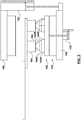
- FIG. 1 there is depicted a schematic representation of a non-limiting embodiment of a molding system 100 that has been configured for the production of molded articles (not shown) such as, for example, preforms of the type for blow molding into containers (not shown).
- the molding system 100 broadly includes a mold clamp 190 for selectively clamping a mold 102 therein, a post-mold device 192 for retrieving molded articles (not shown) from the mold 102, and a controller 170 for controlling various actuators that are associated with the molding system 100.
- the structure and operation of the molding system 100 is generally consistent with the state of the art and hence a detailed description thereof has been omitted herein.
- the mold clamp 190 includes a moveable platen 150, a stationary platen 160 and a platen actuator 162 such as, for example, a hydraulic or electro-mechanical actuator, linking the two together. That being said, those of skill in the art will appreciate that the representation of the mold clamp 190 has been simplified and that not all of the structures thereof have been illustrated.
- the platen actuator 162 is selectively operable, under the control of the controller 170, to selectively move the moveable platen 150 relative to the stationary platen 160 and hence move a moveable mold half 110 relative to a stationary mold half 120 that are associated therewith, respectively.
- the mold clamp 190 includes an ejector actuator 152 such as, for example, a hydraulic or electro-mechanical actuator, that links the moveable platen 150 to a stripping device 140 of the moveable mold half 110.
- the ejector actuator 152 is selectively operable, under the control of the controller 170, to selectively move the stripping device 140 relative to a core assembly 130 of the moveable mold half 110 for ejecting molded articles (not shown) from the moveable mold half 110.
- the post-mold device 192 includes a post-mold tool 180, such as, for example, an end-of-arm tool, that is linked to a carrier actuator 186 such as, for example, a servo motor. That being said, those of skill in the art will appreciate that the representation of the post-mold device 192 has been simplified and that not all of the structures thereof have been illustrated.
- the carrier actuator 186 is selectively operable, under the control of the controller 170, to selectively move the post-mold tool 180 relative to the mold 102 for retrieving the molded articles (not shown) therefrom.
- the post-mold tool 180 is shown to include a set of receptacles 184 within which to receive a set of molded articles received from the mold.
- the post-mold device 180 may further include further sets of receptacles (not shown) for holding multiple sets of molded articles. That is, it is well known in the art to configure the post-mold tool 180 to include multiple sets of receptacles for sake of holding molded articles therein over a duration of multiple molding cycles for enhancing the thermal conditioning (e.g. cooling) thereof. That being said, the number of sets of receptacles that are associated with the post-mold tool 180 is not particularly limited.
- controller 170 is controllably linked to the ejector actuator 152, the platen actuator 162, and the carrier actuator 186 for control thereof in accordance with instructions 172 that are retained in a controller-usable memory 174 of the controller 170. That being said, those of skill in the art will appreciate that the representation of the controller 170 has been simplified and that not all of the structures thereof have been illustrated.
- the instructions 172 direct the controller 170 to execute a method 200 ( FIG. 14 ) of transferring a molded article 104 ( FIG. 3 ) from the mold 102 into a receptacle 184 ( FIG. 3 ) that is associated with the post-mold tool 180.
- the method 200 begins with a step 210 of positioning the moveable mold half 110 relative to the post-mold tool 180 to position the molded article 104 closer to the receptacle 184.
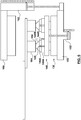
- FIGS. 2-4 To illustrate a non-limiting example of an execution of the foregoing step 210 reference shall now be made to FIGS. 2-4 .
- the step 210 may begin with an operation of separating the moveable mold half 110 from the stationary mold half 120.
- the foregoing involves controlling the platen actuator 162 to reposition the moveable platen 150 away from the stationary platen 160. In so doing, the mold 102 is opened sufficiently that there is enough space for the post-mold tool 180 to enter in between the moveable mold half 110 and the stationary mold half 120.
- the step 210 may further include an operation of positioning the post-mold tool 180 into a receiving position that is between the moveable mold half 110 and the stationary mold half 120 with the receptacles 184 thereof in alignment with the molded articles 104 that are resident on the moveable mold half 110.
- the foregoing operation involves controlling the carrier actuator 186 to position the post-mold tool 180.
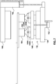
- the step 210 may end with an operation of positioning the moveable mold half 110 closer to the post-mold tool 180 to cause the molded articles 104 that are resident on the moveable mold half 110 to be positioned closer to the receptacles 184. More particularly, the molded articles 104 may be positioned within the receptacles 184.
- the foregoing step involves controlling the platen actuator 162 to position the moveable platen 150 towards the stationary platen 160.
- the method 200 ends or repeats with a step 220 of retracting 220 the moveable mold half 110 while simultaneously extending a stripping device 140 thereof to eject the molded article 104 from the moveable mold half 110 and to transfer it into the receptacle 184.
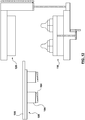
- FIGS. 5-9 To illustrate a non-limiting example of an execution of the foregoing step 220 reference shall now be made to FIGS. 5-9 .
- the step 220 may begin with a first stage of ejection of the molded articles 104 from the moveable mold half wherein the core assembly 130 thereof has been retracted a short distance relative to the stripping device 140 that remains substantially stationary relative to the post-mold tool 180 by virtue of the coordinated control of the ejector actuator 152 and the platen actuator 162. More particularly, the stripping device 140 has been extended with substantially equal and opposite movement to retraction of the core assembly 130 of the moveable mold half 110 such that the stripping device 140 remains substantially stationary relative to the post-mold tool 180 as it ejects the molded article 104 from the moveable mold half 110.
- the foregoing step is a prelude to the opening of a pair of slides 144A, 144B that are slidably linked to the stripping device 140 for opening of a pair of split inserts 146A, 146B that are connected thereto for releasing an encapsulated portion 105 ( FIG. 6 ) of the molded articles 104.
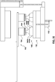
- a second stage of ejection of the molded articles 104 is progressively completed, wherein the pair of slides 144A, 144B are opened (i.e. laterally moved apart) to open (i.e. space apart) the split inserts 146A, 146B to fully release the encapsulated portion 105 ( FIG. 6 ) of the molded articles 104 therefrom.
- the foregoing step again involves effectively retracting the core assembly 130 a further distance relative to the stripping device 140 that remains substantially stationary relative to the post-mold tool 180 by virtue of the coordinated control of the ejector actuator 152 and the platen actuator 162.
- a cam (not shown) that links the pair of slides 144A, 144B to the core assembly 130 drives the opening thereof. That being said, the means by which the pair of slides 144A, 144B are actuated (i.e. opened and closed) is not so limited and may otherwise be actuated, for example, by one or more linear actuators that are associated with the stripping device 140.
- the non-limiting embodiment of the method 200 may further include retracting the stripping device 140.
- the foregoing step involves controlling the ejector actuator 152 to retract the stripping device 140 towards the core assembly 130.
- the method 200 may also further include retracting the moveable mold half 110 relative to the post-mold tool 180 to withdraw the core inserts 132 from the molded articles 104 that are now resident in the receptacles 184.
- the foregoing step involves controlling the platen actuator 162 to reposition the moveable platen 150 away from the stationary platen 160.
- the method 200 may further include positioning the post-mold tool 180 into a transfer position with the withdrawal thereof from between the moveable mold half 110 and the stationary mold half 120 with the molded articles 104 in the receptacles 184.
- the foregoing step involves controlling the carrier actuator 186 to withdraw the post-mold tool 180.
- the method 200 may include closing the mold 102 for sake of being positioned to mold the next batch of molded articles.
- the foregoing step involves controlling the platen actuator 162 to reposition the moveable platen towards from the stationary platen 160.
- the method 200 may lastly include the ejecting of the molded articles 104 from the receptacles 184.
- the foregoing step involves controlling an ejector (not shown) that is associated with the receptacles 184 to eject the molded articles 104 therefrom.
- a technical effect of the foregoing method 200 may include more reliable transfer of the molded articles 104 from the moveable mold half 110 to the receptacles of the post-mold tool 180 by virtue of the positioning of the molded article 104 closer to the receptacles 184 prior to the ejection thereof.
Landscapes
- Engineering & Computer Science (AREA)
- Mechanical Engineering (AREA)
- Manufacturing & Machinery (AREA)
- Robotics (AREA)
- Moulds For Moulding Plastics Or The Like (AREA)
- Injection Moulding Of Plastics Or The Like (AREA)
Claims (10)
- Verfahren (200) zur Übertragung eines Formgegenstands (104) von einer beweglichen Werkzeughälfte (110) eines Formwerkzeugs (102) in einen Behälter (184) eines Nachbehandlungs-Werkzeugs (180), wobei das Verfahren umfasst:Trennen der beweglichen Werkzeughälfte (110) von einer feststehenden Werkzeughälfte (120) des Formwerkzeugs (102),Positionieren (210) des Nachbehandlungs-Werkzeugs (180) in einer Aufnahmestellung, wobei die Aufnahmestellung zwischen der beweglichen Werkzeughälfte (110) und der feststehenden Werkzeughälfte (120) liegt, wobei der Behälter (184) des Nachbehandlungs-Werkzeugs (180) in Ausrichtung mit dem Formgegenstand (104) liegt, der auf der beweglichen Werkzeughälfte (110) ruht, gekennzeichnet durchPositionieren (210) der beweglichen Werkzeughälfte (110) näher zu dem Nachbehandlungs-Werkzeug (180), um den Formgegenstand (104) in den Behälter (184) einzusetzen, undZurückziehen (220) der beweglichen Werkzeughälfte (110), während gleichzeitig eine Abstreifvorrichtung (140) davon ausgefahren wird, um den Formgegenstand (104) von der bewegliche Werkzeughälfte (110) abzuwerfen und ihn in den Behälter (184) zu übertragen.
- Verfahren (200) nach Anspruch 1, wobei:die Abstreifvorrichtung (140) der beweglichen Werkzeughälfte (110) mit einer im Wesentlichen gleichen und dem Zurückziehen der beweglichen Werkzeughälfte (110) entgegengesetzten Bewegung ausgefahren wird, so dass die Abstreifvorrichtung (140) relativ zu dem Nachbehandlungs-Werkzeug (180) feststehend bleibt, während sie den Formgegenstand (104) von der beweglichen Werkzeughälfte (110) abwirft.
- Verfahren (200) nach Anspruch 2, des Weiteren umfassend:Zurückziehen der Abstreifvorrichtung (140), sobald der Formgegenstand (104) von dem beweglichen Werkzeughälfte (110) abgeworfen wurde.
- Verfahren (200) nach Anspruch 3, des Weiteren umfassend:Zurückziehen der beweglichen Werkzeughälfte (110) von dem Nachbehandlungs-Werkzeug (180) weg, um einen Kerneinsatz (132) einer Kernanordnung (130) der beweglichen Werkzeughälfte (110) von dem Formgegenstand (104) wegzuziehen, der in dem Behälter (184) ruht.
- Verfahren (200) nach Anspruch 4, des Weiteren umfassend:Positionieren des Nachbehandlungs-Werkzeugs (180) in eine Übergabestellung mit dem Formgegenstand (104) in dem Behälter (184).
- Steuergerät (170) umfassend Anweisungen (172), die in einem durch das Steuergerät verwendbaren Speicher (174) des Steuergeräts (170) gespeichert sind, wobei die Anweisungen (172) dazu dienen, das Steuergerät (170) anzuleiten, ein Spritzgießsystem (100) zu steuern, um ein Verfahren (200) zur Übertragung eines Formgegenstands (104) von einer beweglichen Werkzeughälfte (110) eines Formwerkzeugs (102) in einen Behälter (184) eines Nachbehandlungs-Werkzeugs (180) auszuführen, das umfasst:Steuern eines Aufspannplattenstellglieds (162), um die bewegliche Aufspannplatte (150) des Spritzgießsystems (100) von einer feststehenden Aufspannplatte (160) des Spritzgießsystems (100) weg umzustellen, um die bewegliche Werkzeughälfte (110) von der feststehenden Werkzeughälfte (120) des Formwerkzeugs zu trennen,Steuern eines Trägerstellglieds (186), um das Nachbehandlungs-Werkzeug (180) in eine Aufnahmestellung zu bewegen, wobei die Aufnahmestellung zwischen der beweglichen Werkzeughälfte (110) und der feststehenden Werkzeughälfte (120) liegt, wobei der Behälter (184) des Nachbehandlungs-Werkzeugs (180) in Ausrichtung mit dem Formgegenstand (104) liegt, der auf der beweglichen Werkzeughälfte (110) ruht, gekennzeichnet durchSteuern des Aufspannplattenstellglieds (162), um die bewegliche Werkzeughälfte (110), die an der beweglichen Aufspannplatte (150) montiert ist, näher an dem Nachbehandlungs-Werkzeug (180) zu positionieren, um die Einführung des Formgegenstands (104) in den Behälter (184) zu veranlassen, undSteuern des Aufspannplattenstellglieds (162), um die bewegliche Aufspannplatte (150) von dem Nachbehandlungs-Werkzeug (180) weg zu bewegen und dadurch die bewegliche Werkzeughälfte (110) von dem Nachbehandlungs-Werkzeug (180) weg zu ziehen, während gleichzeitig ein Auswerferstellglied (152) gesteuert wird, eine Abstreifvorrichtung (140) der beweglichen Werkzeughälfte (110) auszufahren, um den Formgegenstand (104) von der beweglichen Werkzeughälfte (110) abzuwerfen und ihn in den Behälter (184) zu übertragen.
- Steuergerät (170) nach Anspruch 6, wobei:das Aufspannplattenstellglied (162) und das Auswerferstellglied (152) so gesteuert werden, dass die Abstreifvorrichtung (140) mit einer im Wesentlichen gleichen und dem Zurückziehen der beweglichen Werkzeughälfte (110) entgegengesetzten Bewegung ausgefahren wird, so dass die Abstreifvorrichtung (140) relativ zu dem Nachbehandlungs-Werkzeug (180) feststehend bleibt, während sie den Formgegenstand von der beweglichen Werkzeughälfte (110) abwirft.
- Steuergerät (170) nach Anspruch 6, des Weiteren umfassend die folgenden Anweisungen (172):Steuern des Abstreiferstellglieds (152), um die Abstreifvorrichtung (140) zurückzuziehen, sobald der Formgegenstand (104) von der beweglichen Werkzeughälfte (110) abgeworfen wurde.
- Steuergerät (170) nach Anspruch 7, des Weiteren umfassend die folgenden Anweisungen (172):Steuern des Aufspannplattenstellglieds (162), um die bewegliche Werkzeughälfte (150) von dem Nachbehandlungs-Werkzeug (180) umzustellen, um einen Kerneinsatz (132) einer Kernanordnung (130) von dem Formgegenstand (104) wegzuziehen, der in dem Behälter (184) ruht.
- Steuergerät (170) nach Anspruch 6, des Weiteren umfassend die folgenden Anweisungen (172):Steuern des Trägerstellglieds (186), um das Nachbehandlungs-Werkzeug (180) in eine Übergabestellung zurückzuziehen, mit dem Formgegenstand (104) in dem Behälter (184).
Applications Claiming Priority (2)
| Application Number | Priority Date | Filing Date | Title |
|---|---|---|---|
| US201261651289P | 2012-05-24 | 2012-05-24 | |
| PCT/CA2013/050352 WO2013173918A1 (en) | 2012-05-24 | 2013-05-07 | A method of transferring a molded article |
Publications (3)
| Publication Number | Publication Date |
|---|---|
| EP2877334A1 EP2877334A1 (de) | 2015-06-03 |
| EP2877334A4 EP2877334A4 (de) | 2016-05-25 |
| EP2877334B1 true EP2877334B1 (de) | 2017-07-26 |
Family
ID=49622970
Family Applications (1)
| Application Number | Title | Priority Date | Filing Date |
|---|---|---|---|
| EP13794010.2A Active EP2877334B1 (de) | 2012-05-24 | 2013-05-07 | Verfahren und controller zur übertragung eines formartikels |
Country Status (3)
| Country | Link |
|---|---|
| US (1) | US10131084B2 (de) |
| EP (1) | EP2877334B1 (de) |
| WO (1) | WO2013173918A1 (de) |
Families Citing this family (3)
| Publication number | Priority date | Publication date | Assignee | Title |
|---|---|---|---|---|
| EP3523110B8 (de) | 2016-10-05 | 2023-06-07 | Husky Injection Molding Systems Ltd. | Verfahren zur steuerung einer giessvorrichtung |
| CA3048490A1 (en) * | 2017-01-06 | 2018-07-12 | Friendship Products Llc | Molding systems and related methods |
| CN109262998A (zh) * | 2018-11-06 | 2019-01-25 | 浙江橡企科技有限公司 | 一种自动化成模装置 |
Family Cites Families (8)
| Publication number | Priority date | Publication date | Assignee | Title |
|---|---|---|---|---|
| US5653934A (en) * | 1995-05-05 | 1997-08-05 | Electra Form, Inc. | Molded part take-out apparatus |
| CN1083760C (zh) * | 1996-09-02 | 2002-05-01 | 日精Asb机械株式会社 | 注坯吹塑设备、注坯吹塑方法和注塑设备 |
| US6848900B2 (en) * | 2002-07-13 | 2005-02-01 | Husky Injection Molding Systems Ltd. | Apparatus for handling injection molded preforms |
| JP4512462B2 (ja) * | 2004-09-24 | 2010-07-28 | 東芝機械株式会社 | 成形機の制御システム |
| US7611739B2 (en) | 2006-01-06 | 2009-11-03 | Amerilab Technologies, Inc. | Method of using guava extract and composition including guava extract |
| US20080268087A1 (en) * | 2007-04-30 | 2008-10-30 | Husky Injection Molding Systems Ltd. | Locking Structure for Molded Parts in a Molding Machine |
| EP2323831B1 (de) | 2008-08-14 | 2012-09-19 | Husky Injection Molding Systems Ltd. | Abziehvorrichtung für einen formstapel für einen vorformling und und formstapel für einen vorformling |
| CN103934993B (zh) | 2009-11-30 | 2017-01-18 | 赫斯基注塑系统有限公司 | 具有往返运动的成模物件转移设备 |
-
2013
- 2013-05-07 WO PCT/CA2013/050352 patent/WO2013173918A1/en active Application Filing
- 2013-05-07 US US14/401,538 patent/US10131084B2/en active Active
- 2013-05-07 EP EP13794010.2A patent/EP2877334B1/de active Active
Non-Patent Citations (1)
| Title |
|---|
| None * |
Also Published As
| Publication number | Publication date |
|---|---|
| EP2877334A4 (de) | 2016-05-25 |
| EP2877334A1 (de) | 2015-06-03 |
| US20150130113A1 (en) | 2015-05-14 |
| WO2013173918A1 (en) | 2013-11-28 |
| US10131084B2 (en) | 2018-11-20 |
Similar Documents
| Publication | Publication Date | Title |
|---|---|---|
| US20150076735A1 (en) | Injection molding machine | |
| US8459977B2 (en) | Molded article transfer device | |
| EP2877334B1 (de) | Verfahren und controller zur übertragung eines formartikels | |
| WO2011063499A1 (en) | A molded article transfer device with shuttling movement | |
| EP2864098B1 (de) | Formeinsatz mit luftventil und giessverfahren | |
| CN103737856A (zh) | 打印机面板被动顺序式合模精密模具 | |
| EP2581198A1 (de) | System zum öffnen beweglicher elemente in formen in einer reihenfolge zur extraktion geformter teile | |
| US9415535B2 (en) | Multistage ejection of an injection molded material | |
| WO2012162786A1 (en) | Injection molding process | |
| CN104245271B (zh) | 用于车辆保险杠面板的模具和相关联的成型技术 | |
| EP2019744B1 (de) | System zum integrieren eines einsatzes mit einem formkörper | |
| JP2017087702A (ja) | モールド部付電線保護部材の成形装置 | |
| JP4928283B2 (ja) | 射出成形機 | |
| CN107877776B (zh) | 注塑模具及应用该注塑模具的注塑方法 | |
| CN106426811B (zh) | 具有软性镶件的汽车仪表板的成型模具 | |
| JP6441405B2 (ja) | 複数個の成形品を並行して成形する成形方法および成形装置 | |
| CA2853001C (en) | An apparatus for use with a mold which includes a cavity blocker | |
| WO2014169380A1 (en) | Molding apparatus and molding process | |
| US20220281149A1 (en) | Molding apparatus and method of controlling same | |
| US11040473B2 (en) | Systems and methods for operating an injection molding machine | |
| JP2010284930A (ja) | 射出成形機のエジェクト方法 | |
| JP2006095749A (ja) | 成形品、成形品成形装置、および成形品成形方法 | |
| WO2013067634A1 (en) | A transfer device for molded articles | |
| US20160158983A1 (en) | Perimeter ejection of an injection molded material | |
| JP2006035672A (ja) | 吹込成形方法 |
Legal Events
| Date | Code | Title | Description |
|---|---|---|---|
| PUAI | Public reference made under article 153(3) epc to a published international application that has entered the european phase |
Free format text: ORIGINAL CODE: 0009012 |
|
| 17P | Request for examination filed |
Effective date: 20150105 |
|
| AK | Designated contracting states |
Kind code of ref document: A1 Designated state(s): AL AT BE BG CH CY CZ DE DK EE ES FI FR GB GR HR HU IE IS IT LI LT LU LV MC MK MT NL NO PL PT RO RS SE SI SK SM TR |
|
| AX | Request for extension of the european patent |
Extension state: BA ME |
|
| DAX | Request for extension of the european patent (deleted) | ||
| RAP1 | Party data changed (applicant data changed or rights of an application transferred) |
Owner name: HUSKY INJECTION MOLDING SYSTEMS LUXEMBOURG IP DEVE |
|
| RA4 | Supplementary search report drawn up and despatched (corrected) |
Effective date: 20160425 |
|
| RIC1 | Information provided on ipc code assigned before grant |
Ipc: B29C 49/70 20060101ALI20160419BHEP Ipc: B25J 9/16 20060101ALI20160419BHEP Ipc: B29C 45/42 20060101ALI20160419BHEP Ipc: B25J 11/00 20060101ALI20160419BHEP Ipc: B29C 45/40 20060101AFI20160419BHEP Ipc: B29C 45/78 20060101ALI20160419BHEP Ipc: B29C 45/38 20060101ALI20160419BHEP Ipc: B29C 45/70 20060101ALI20160419BHEP Ipc: B29C 49/78 20060101ALI20160419BHEP |
|
| GRAP | Despatch of communication of intention to grant a patent |
Free format text: ORIGINAL CODE: EPIDOSNIGR1 |
|
| INTG | Intention to grant announced |
Effective date: 20170406 |
|
| GRAS | Grant fee paid |
Free format text: ORIGINAL CODE: EPIDOSNIGR3 |
|
| GRAA | (expected) grant |
Free format text: ORIGINAL CODE: 0009210 |
|
| RAP1 | Party data changed (applicant data changed or rights of an application transferred) |
Owner name: HUSKY INJECTION MOLDING SYSTEMS LTD. |
|
| AK | Designated contracting states |
Kind code of ref document: B1 Designated state(s): AL AT BE BG CH CY CZ DE DK EE ES FI FR GB GR HR HU IE IS IT LI LT LU LV MC MK MT NL NO PL PT RO RS SE SI SK SM TR |
|
| REG | Reference to a national code |
Ref country code: GB Ref legal event code: FG4D |
|
| REG | Reference to a national code |
Ref country code: CH Ref legal event code: EP |
|
| REG | Reference to a national code |
Ref country code: AT Ref legal event code: REF Ref document number: 912010 Country of ref document: AT Kind code of ref document: T Effective date: 20170815 |
|
| REG | Reference to a national code |
Ref country code: IE Ref legal event code: FG4D |
|
| REG | Reference to a national code |
Ref country code: DE Ref legal event code: R096 Ref document number: 602013024133 Country of ref document: DE |
|
| REG | Reference to a national code |
Ref country code: NL Ref legal event code: MP Effective date: 20170726 |
|
| REG | Reference to a national code |
Ref country code: LT Ref legal event code: MG4D |
|
| REG | Reference to a national code |
Ref country code: AT Ref legal event code: MK05 Ref document number: 912010 Country of ref document: AT Kind code of ref document: T Effective date: 20170726 |
|
| PG25 | Lapsed in a contracting state [announced via postgrant information from national office to epo] |
Ref country code: FI Free format text: LAPSE BECAUSE OF FAILURE TO SUBMIT A TRANSLATION OF THE DESCRIPTION OR TO PAY THE FEE WITHIN THE PRESCRIBED TIME-LIMIT Effective date: 20170726 Ref country code: NO Free format text: LAPSE BECAUSE OF FAILURE TO SUBMIT A TRANSLATION OF THE DESCRIPTION OR TO PAY THE FEE WITHIN THE PRESCRIBED TIME-LIMIT Effective date: 20171026 Ref country code: AT Free format text: LAPSE BECAUSE OF FAILURE TO SUBMIT A TRANSLATION OF THE DESCRIPTION OR TO PAY THE FEE WITHIN THE PRESCRIBED TIME-LIMIT Effective date: 20170726 Ref country code: NL Free format text: LAPSE BECAUSE OF FAILURE TO SUBMIT A TRANSLATION OF THE DESCRIPTION OR TO PAY THE FEE WITHIN THE PRESCRIBED TIME-LIMIT Effective date: 20170726 Ref country code: HR Free format text: LAPSE BECAUSE OF FAILURE TO SUBMIT A TRANSLATION OF THE DESCRIPTION OR TO PAY THE FEE WITHIN THE PRESCRIBED TIME-LIMIT Effective date: 20170726 Ref country code: LT Free format text: LAPSE BECAUSE OF FAILURE TO SUBMIT A TRANSLATION OF THE DESCRIPTION OR TO PAY THE FEE WITHIN THE PRESCRIBED TIME-LIMIT Effective date: 20170726 Ref country code: SE Free format text: LAPSE BECAUSE OF FAILURE TO SUBMIT A TRANSLATION OF THE DESCRIPTION OR TO PAY THE FEE WITHIN THE PRESCRIBED TIME-LIMIT Effective date: 20170726 |
|
| PG25 | Lapsed in a contracting state [announced via postgrant information from national office to epo] |
Ref country code: GR Free format text: LAPSE BECAUSE OF FAILURE TO SUBMIT A TRANSLATION OF THE DESCRIPTION OR TO PAY THE FEE WITHIN THE PRESCRIBED TIME-LIMIT Effective date: 20171027 Ref country code: IS Free format text: LAPSE BECAUSE OF FAILURE TO SUBMIT A TRANSLATION OF THE DESCRIPTION OR TO PAY THE FEE WITHIN THE PRESCRIBED TIME-LIMIT Effective date: 20171126 Ref country code: LV Free format text: LAPSE BECAUSE OF FAILURE TO SUBMIT A TRANSLATION OF THE DESCRIPTION OR TO PAY THE FEE WITHIN THE PRESCRIBED TIME-LIMIT Effective date: 20170726 Ref country code: ES Free format text: LAPSE BECAUSE OF FAILURE TO SUBMIT A TRANSLATION OF THE DESCRIPTION OR TO PAY THE FEE WITHIN THE PRESCRIBED TIME-LIMIT Effective date: 20170726 Ref country code: BG Free format text: LAPSE BECAUSE OF FAILURE TO SUBMIT A TRANSLATION OF THE DESCRIPTION OR TO PAY THE FEE WITHIN THE PRESCRIBED TIME-LIMIT Effective date: 20171026 Ref country code: RS Free format text: LAPSE BECAUSE OF FAILURE TO SUBMIT A TRANSLATION OF THE DESCRIPTION OR TO PAY THE FEE WITHIN THE PRESCRIBED TIME-LIMIT Effective date: 20170726 Ref country code: PL Free format text: LAPSE BECAUSE OF FAILURE TO SUBMIT A TRANSLATION OF THE DESCRIPTION OR TO PAY THE FEE WITHIN THE PRESCRIBED TIME-LIMIT Effective date: 20170726 |
|
| REG | Reference to a national code |
Ref country code: FR Ref legal event code: PLFP Year of fee payment: 6 |
|
| PG25 | Lapsed in a contracting state [announced via postgrant information from national office to epo] |
Ref country code: DK Free format text: LAPSE BECAUSE OF FAILURE TO SUBMIT A TRANSLATION OF THE DESCRIPTION OR TO PAY THE FEE WITHIN THE PRESCRIBED TIME-LIMIT Effective date: 20170726 Ref country code: CZ Free format text: LAPSE BECAUSE OF FAILURE TO SUBMIT A TRANSLATION OF THE DESCRIPTION OR TO PAY THE FEE WITHIN THE PRESCRIBED TIME-LIMIT Effective date: 20170726 Ref country code: RO Free format text: LAPSE BECAUSE OF FAILURE TO SUBMIT A TRANSLATION OF THE DESCRIPTION OR TO PAY THE FEE WITHIN THE PRESCRIBED TIME-LIMIT Effective date: 20170726 |
|
| REG | Reference to a national code |
Ref country code: DE Ref legal event code: R097 Ref document number: 602013024133 Country of ref document: DE |
|
| PG25 | Lapsed in a contracting state [announced via postgrant information from national office to epo] |
Ref country code: SK Free format text: LAPSE BECAUSE OF FAILURE TO SUBMIT A TRANSLATION OF THE DESCRIPTION OR TO PAY THE FEE WITHIN THE PRESCRIBED TIME-LIMIT Effective date: 20170726 Ref country code: IT Free format text: LAPSE BECAUSE OF FAILURE TO SUBMIT A TRANSLATION OF THE DESCRIPTION OR TO PAY THE FEE WITHIN THE PRESCRIBED TIME-LIMIT Effective date: 20170726 Ref country code: EE Free format text: LAPSE BECAUSE OF FAILURE TO SUBMIT A TRANSLATION OF THE DESCRIPTION OR TO PAY THE FEE WITHIN THE PRESCRIBED TIME-LIMIT Effective date: 20170726 Ref country code: SM Free format text: LAPSE BECAUSE OF FAILURE TO SUBMIT A TRANSLATION OF THE DESCRIPTION OR TO PAY THE FEE WITHIN THE PRESCRIBED TIME-LIMIT Effective date: 20170726 |
|
| PLBE | No opposition filed within time limit |
Free format text: ORIGINAL CODE: 0009261 |
|
| STAA | Information on the status of an ep patent application or granted ep patent |
Free format text: STATUS: NO OPPOSITION FILED WITHIN TIME LIMIT |
|
| 26N | No opposition filed |
Effective date: 20180430 |
|
| PG25 | Lapsed in a contracting state [announced via postgrant information from national office to epo] |
Ref country code: SI Free format text: LAPSE BECAUSE OF FAILURE TO SUBMIT A TRANSLATION OF THE DESCRIPTION OR TO PAY THE FEE WITHIN THE PRESCRIBED TIME-LIMIT Effective date: 20170726 |
|
| REG | Reference to a national code |
Ref country code: BE Ref legal event code: MM Effective date: 20180531 |
|
| PG25 | Lapsed in a contracting state [announced via postgrant information from national office to epo] |
Ref country code: MC Free format text: LAPSE BECAUSE OF FAILURE TO SUBMIT A TRANSLATION OF THE DESCRIPTION OR TO PAY THE FEE WITHIN THE PRESCRIBED TIME-LIMIT Effective date: 20170726 |
|
| REG | Reference to a national code |
Ref country code: IE Ref legal event code: MM4A |
|
| PG25 | Lapsed in a contracting state [announced via postgrant information from national office to epo] |
Ref country code: IE Free format text: LAPSE BECAUSE OF NON-PAYMENT OF DUE FEES Effective date: 20180507 |
|
| PG25 | Lapsed in a contracting state [announced via postgrant information from national office to epo] |
Ref country code: BE Free format text: LAPSE BECAUSE OF NON-PAYMENT OF DUE FEES Effective date: 20180531 |
|
| PG25 | Lapsed in a contracting state [announced via postgrant information from national office to epo] |
Ref country code: MT Free format text: LAPSE BECAUSE OF NON-PAYMENT OF DUE FEES Effective date: 20180507 |
|
| PG25 | Lapsed in a contracting state [announced via postgrant information from national office to epo] |
Ref country code: TR Free format text: LAPSE BECAUSE OF FAILURE TO SUBMIT A TRANSLATION OF THE DESCRIPTION OR TO PAY THE FEE WITHIN THE PRESCRIBED TIME-LIMIT Effective date: 20170726 |
|
| PG25 | Lapsed in a contracting state [announced via postgrant information from national office to epo] |
Ref country code: PT Free format text: LAPSE BECAUSE OF FAILURE TO SUBMIT A TRANSLATION OF THE DESCRIPTION OR TO PAY THE FEE WITHIN THE PRESCRIBED TIME-LIMIT Effective date: 20170726 |
|
| PG25 | Lapsed in a contracting state [announced via postgrant information from national office to epo] |
Ref country code: CY Free format text: LAPSE BECAUSE OF FAILURE TO SUBMIT A TRANSLATION OF THE DESCRIPTION OR TO PAY THE FEE WITHIN THE PRESCRIBED TIME-LIMIT Effective date: 20170726 Ref country code: MK Free format text: LAPSE BECAUSE OF NON-PAYMENT OF DUE FEES Effective date: 20170726 Ref country code: HU Free format text: LAPSE BECAUSE OF FAILURE TO SUBMIT A TRANSLATION OF THE DESCRIPTION OR TO PAY THE FEE WITHIN THE PRESCRIBED TIME-LIMIT; INVALID AB INITIO Effective date: 20130507 |
|
| PG25 | Lapsed in a contracting state [announced via postgrant information from national office to epo] |
Ref country code: AL Free format text: LAPSE BECAUSE OF FAILURE TO SUBMIT A TRANSLATION OF THE DESCRIPTION OR TO PAY THE FEE WITHIN THE PRESCRIBED TIME-LIMIT Effective date: 20170726 |
|
| P01 | Opt-out of the competence of the unified patent court (upc) registered |
Effective date: 20230516 |
|
| PGFP | Annual fee paid to national office [announced via postgrant information from national office to epo] |
Ref country code: LU Payment date: 20240409 Year of fee payment: 12 |
|
| PGFP | Annual fee paid to national office [announced via postgrant information from national office to epo] |
Ref country code: GB Payment date: 20240409 Year of fee payment: 12 |
|
| PGFP | Annual fee paid to national office [announced via postgrant information from national office to epo] |
Ref country code: DE Payment date: 20240503 Year of fee payment: 12 |
|
| PGFP | Annual fee paid to national office [announced via postgrant information from national office to epo] |
Ref country code: CH Payment date: 20240602 Year of fee payment: 12 |
|
| PGFP | Annual fee paid to national office [announced via postgrant information from national office to epo] |
Ref country code: FR Payment date: 20240409 Year of fee payment: 12 |