EP2877273B1 - Verfahren und vorrichtung zur herstellung einer nanoporösen membran - Google Patents
Verfahren und vorrichtung zur herstellung einer nanoporösen membran Download PDFInfo
- Publication number
- EP2877273B1 EP2877273B1 EP13747467.2A EP13747467A EP2877273B1 EP 2877273 B1 EP2877273 B1 EP 2877273B1 EP 13747467 A EP13747467 A EP 13747467A EP 2877273 B1 EP2877273 B1 EP 2877273B1
- Authority
- EP
- European Patent Office
- Prior art keywords
- membrane
- pore
- ions
- ion beam
- generator
- Prior art date
- Legal status (The legal status is an assumption and is not a legal conclusion. Google has not performed a legal analysis and makes no representation as to the accuracy of the status listed.)
- Active
Links
- 239000012528 membrane Substances 0.000 title claims description 114
- 238000000034 method Methods 0.000 title claims description 32
- 239000011148 porous material Substances 0.000 claims description 87
- 150000002500 ions Chemical class 0.000 claims description 66
- 238000010884 ion-beam technique Methods 0.000 claims description 38
- 239000002245 particle Substances 0.000 claims description 26
- 239000000463 material Substances 0.000 claims description 10
- 230000003287 optical effect Effects 0.000 claims description 10
- 229910001338 liquidmetal Inorganic materials 0.000 claims description 7
- 229910052581 Si3N4 Inorganic materials 0.000 claims description 3
- VYPSYNLAJGMNEJ-UHFFFAOYSA-N Silicium dioxide Chemical compound O=[Si]=O VYPSYNLAJGMNEJ-UHFFFAOYSA-N 0.000 claims description 3
- 238000004220 aggregation Methods 0.000 claims description 3
- 230000002776 aggregation Effects 0.000 claims description 3
- HBMJWWWQQXIZIP-UHFFFAOYSA-N silicon carbide Chemical compound [Si+]#[C-] HBMJWWWQQXIZIP-UHFFFAOYSA-N 0.000 claims description 3
- 229910010271 silicon carbide Inorganic materials 0.000 claims description 3
- HQVNEWCFYHHQES-UHFFFAOYSA-N silicon nitride Chemical compound N12[Si]34N5[Si]62N3[Si]51N64 HQVNEWCFYHHQES-UHFFFAOYSA-N 0.000 claims description 3
- 229910052814 silicon oxide Inorganic materials 0.000 claims description 3
- 230000015572 biosynthetic process Effects 0.000 claims description 2
- 230000001678 irradiating effect Effects 0.000 claims description 2
- 230000008685 targeting Effects 0.000 claims 1
- 238000009434 installation Methods 0.000 description 19
- 230000008569 process Effects 0.000 description 10
- 238000005553 drilling Methods 0.000 description 6
- 238000001514 detection method Methods 0.000 description 5
- 238000006073 displacement reaction Methods 0.000 description 5
- 238000004519 manufacturing process Methods 0.000 description 5
- 238000005530 etching Methods 0.000 description 4
- 229910052751 metal Inorganic materials 0.000 description 4
- 239000002184 metal Substances 0.000 description 4
- XUIMIQQOPSSXEZ-UHFFFAOYSA-N Silicon Chemical compound [Si] XUIMIQQOPSSXEZ-UHFFFAOYSA-N 0.000 description 3
- 229910021645 metal ion Inorganic materials 0.000 description 3
- 239000011163 secondary particle Substances 0.000 description 3
- 239000000126 substance Substances 0.000 description 3
- 101100536354 Drosophila melanogaster tant gene Proteins 0.000 description 2
- GYHNNYVSQQEPJS-UHFFFAOYSA-N Gallium Chemical compound [Ga] GYHNNYVSQQEPJS-UHFFFAOYSA-N 0.000 description 2
- 238000009792 diffusion process Methods 0.000 description 2
- 230000000694 effects Effects 0.000 description 2
- 230000003628 erosive effect Effects 0.000 description 2
- 229910052733 gallium Inorganic materials 0.000 description 2
- 238000003384 imaging method Methods 0.000 description 2
- 230000007246 mechanism Effects 0.000 description 2
- 238000007493 shaping process Methods 0.000 description 2
- 229910001020 Au alloy Inorganic materials 0.000 description 1
- 238000013459 approach Methods 0.000 description 1
- 230000005493 condensed matter Effects 0.000 description 1
- 239000000470 constituent Substances 0.000 description 1
- 238000011109 contamination Methods 0.000 description 1
- 239000002178 crystalline material Substances 0.000 description 1
- 230000006866 deterioration Effects 0.000 description 1
- 238000010586 diagram Methods 0.000 description 1
- 230000005684 electric field Effects 0.000 description 1
- 238000001493 electron microscopy Methods 0.000 description 1
- 238000001962 electrophoresis Methods 0.000 description 1
- 238000005429 filling process Methods 0.000 description 1
- 239000010408 film Substances 0.000 description 1
- 239000011888 foil Substances 0.000 description 1
- 239000003353 gold alloy Substances 0.000 description 1
- 238000012625 in-situ measurement Methods 0.000 description 1
- 230000010354 integration Effects 0.000 description 1
- 230000003993 interaction Effects 0.000 description 1
- 229920002521 macromolecule Polymers 0.000 description 1
- 238000005259 measurement Methods 0.000 description 1
- 238000005459 micromachining Methods 0.000 description 1
- 150000004767 nitrides Chemical class 0.000 description 1
- 230000000149 penetrating effect Effects 0.000 description 1
- 238000012545 processing Methods 0.000 description 1
- 230000000644 propagated effect Effects 0.000 description 1
- 238000012552 review Methods 0.000 description 1
- 238000004544 sputter deposition Methods 0.000 description 1
- 239000000758 substrate Substances 0.000 description 1
- 239000010409 thin film Substances 0.000 description 1
Images


Classifications
-
- B—PERFORMING OPERATIONS; TRANSPORTING
- B01—PHYSICAL OR CHEMICAL PROCESSES OR APPARATUS IN GENERAL
- B01D—SEPARATION
- B01D71/00—Semi-permeable membranes for separation processes or apparatus characterised by the material; Manufacturing processes specially adapted therefor
- B01D71/02—Inorganic material
- B01D71/0215—Silicon carbide; Silicon nitride; Silicon oxycarbide
-
- H—ELECTRICITY
- H01—ELECTRIC ELEMENTS
- H01J—ELECTRIC DISCHARGE TUBES OR DISCHARGE LAMPS
- H01J37/00—Discharge tubes with provision for introducing objects or material to be exposed to the discharge, e.g. for the purpose of examination or processing thereof
- H01J37/02—Details
- H01J37/244—Detectors; Associated components or circuits therefor
-
- B—PERFORMING OPERATIONS; TRANSPORTING
- B01—PHYSICAL OR CHEMICAL PROCESSES OR APPARATUS IN GENERAL
- B01D—SEPARATION
- B01D67/00—Processes specially adapted for manufacturing semi-permeable membranes for separation processes or apparatus
- B01D67/0039—Inorganic membrane manufacture
- B01D67/0053—Inorganic membrane manufacture by inducing porosity into non porous precursor membranes
- B01D67/006—Inorganic membrane manufacture by inducing porosity into non porous precursor membranes by elimination of segments of the precursor, e.g. nucleation-track membranes, lithography or laser methods
-
- B—PERFORMING OPERATIONS; TRANSPORTING
- B01—PHYSICAL OR CHEMICAL PROCESSES OR APPARATUS IN GENERAL
- B01D—SEPARATION
- B01D71/00—Semi-permeable membranes for separation processes or apparatus characterised by the material; Manufacturing processes specially adapted therefor
- B01D71/02—Inorganic material
-
- H—ELECTRICITY
- H01—ELECTRIC ELEMENTS
- H01J—ELECTRIC DISCHARGE TUBES OR DISCHARGE LAMPS
- H01J37/00—Discharge tubes with provision for introducing objects or material to be exposed to the discharge, e.g. for the purpose of examination or processing thereof
- H01J37/30—Electron-beam or ion-beam tubes for localised treatment of objects
- H01J37/305—Electron-beam or ion-beam tubes for localised treatment of objects for casting, melting, evaporating or etching
- H01J37/3053—Electron-beam or ion-beam tubes for localised treatment of objects for casting, melting, evaporating or etching for evaporating or etching
- H01J37/3056—Electron-beam or ion-beam tubes for localised treatment of objects for casting, melting, evaporating or etching for evaporating or etching for microworking, e.g. etching of gratings, trimming of electrical components
-
- B—PERFORMING OPERATIONS; TRANSPORTING
- B01—PHYSICAL OR CHEMICAL PROCESSES OR APPARATUS IN GENERAL
- B01D—SEPARATION
- B01D2323/00—Details relating to membrane preparation
- B01D2323/34—Use of radiation
-
- B—PERFORMING OPERATIONS; TRANSPORTING
- B01—PHYSICAL OR CHEMICAL PROCESSES OR APPARATUS IN GENERAL
- B01D—SEPARATION
- B01D61/00—Processes of separation using semi-permeable membranes, e.g. dialysis, osmosis or ultrafiltration; Apparatus, accessories or auxiliary operations specially adapted therefor
- B01D61/02—Reverse osmosis; Hyperfiltration ; Nanofiltration
- B01D61/027—Nanofiltration
-
- H—ELECTRICITY
- H01—ELECTRIC ELEMENTS
- H01J—ELECTRIC DISCHARGE TUBES OR DISCHARGE LAMPS
- H01J2237/00—Discharge tubes exposing object to beam, e.g. for analysis treatment, etching, imaging
- H01J2237/244—Detection characterized by the detecting means
- H01J2237/24455—Transmitted particle detectors
-
- H—ELECTRICITY
- H01—ELECTRIC ELEMENTS
- H01J—ELECTRIC DISCHARGE TUBES OR DISCHARGE LAMPS
- H01J2237/00—Discharge tubes exposing object to beam, e.g. for analysis treatment, etching, imaging
- H01J2237/30—Electron or ion beam tubes for processing objects
- H01J2237/317—Processing objects on a microscale
- H01J2237/31749—Focused ion beam
Definitions
- the present invention relates to processes and installations for forming nano-porous membranes.
- the object of the present invention is in particular to provide such manufacture.
- the invention relates to an installation for forming a nanoporous membrane according to claim 16.
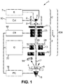
- the figure 1 represents an installation 1 suitable for the implementation of a nanoporous membrane treatment method.
- One architecture of such an installation takes up that of a focused ion beam (FIB, for “focused ion beam”) emission column. It comprises in particular an ion beam generator 100 fitted with a source 2 and an optic 3.
- the installation also comprises a sample holder 4 carrying a sample 5.
- the source, the optics and the sample holder are arranged one after the other, in this order, along an X axis of the generator.
- the source is a liquid metal ion source (LMIS, for “liquid metal ion source”). It comprises a tip 6 electrically connected to a generator 7. The generator supplies tip 6 with a voltage making it possible to polarize the tip.
- the tip is made with a core, for example of a metal refractory, carrying a continuous layer of metal on its surface.
- the metal for example gallium, or a gold alloy, or other, is for example also contained in a reservoir 8 from which it flows towards the end of the tip.
- the ion source 2 also comprises an extractor electrode 9 which can be powered by a dedicated generator 10, in order to generate a potential difference between an extractor electrode 9 and the tip 6. This potential difference generates an electric field which is capable of to extract liquid metal ions, or clusters of these ions from the tip 6.
- the ions thus extracted are propagated in a beam 17 generally in the direction of the sample holder 4 along the axis X.
- the optics 3 comprises a series of lenses suitable for shaping the ion beam. Note in particular a lens 11, close to the source 2, suitable for shaping the ion beam, and an object lens 12 close to the sample holder 4, suitable for concentrating the ion beam in the direction of the sample holder. sample 4.
- a scanning device 13 is provided to spread the ion beam over a given area of the sample holder 4.
- This scanning generator 22 comprises one or more electrodes 13 suitable for electrically influencing the charged particles passing nearby, to deviate their trajectory, in a manner changing over time, in the direction of given points of the sample holder 4.
- the scanning device 13 makes it possible to spread the beam over an area of the membrane , of large surface area relative to the diameter of the pore, for example of the order of 100 nm ⁇ 100 nm.
- the installation also comprises a beam erasing system comprising a series of electrostatic deflectors 25, for example located close to the source 2, and a stop electrode 24, located downstream of the lenses 25, and comprising a through opening 26 of small diameter.
- a beam erasing system constitutes an electrostatic gate for the beam, the “open” or “closed” states of which can be controlled at will.
- the erase generator 18 can power the electrodes 25 so as to cause the beam 17 to pass through the aperture 26 (as shown), or to direct it towards the stop electrode 24.
- the generator 18 is for example a fast bistable voltage generator, allowing a rise or fall time of less than a microsecond.
- the sample holder 4 carries a membrane 5 to be formed.
- the membrane 5 is for example made up of a thin film of mechanically resistant material, such as a silicon carbide, oxide or nitride, or the like. It is for example a non-crystalline film.
- An example of a constituent material is Si 3 N 4 .
- the membrane 5 is 100 nm thick, in particular less than 25 nm thick, or even less than 10 nm thick.
- a detector 15 is used located downstream of the sample holder 4 along the X axis. Thus, the sample holder 4 is arranged between the source 2 and the detector 15.
- a particle detector is used, suitable for detecting particles, in particular electrically charged particles, flowing from the source: the charged ions or clusters coming from the source 2.
- a particle detector a detector capable of detect the low signal levels expected with such ion sources. It is, for example, a detector of the channeltron type, or multichannel plates.
- the installation 1 also comprises a central unit 16 connected to the detector 15.
- the central unit 16 is capable of determining the number of particles detected by the detector 15.
- a secondary particle detector 15 arranged off the optical axis, and placed opposite the upper face (that facing the source 2) of a target placed downstream of the sample holder 4, and detecting so-called secondary electrons, projected from the target due to the arrival thereon of charged particles from source 2.
- the number of charged particles crossing the membrane can be determined, indirectly, from the measured signal by the secondary electron detector.
- the rest of the description refers to the embodiment using the downstream detector 15 of the direct type arranged along the optical axis.
- the central unit 16 is also capable of controlling the arrival of the beam 17 at the level of the sample holder 4.
- the central unit 16 is connected to the scanning generator 13.
- the central unit 16 is capable of comparing the number of particles detected by the detector 15 with a predetermined threshold level, and, according to this comparison, of influencing the arrival of the beam 17 at the level of the sample holder 4.
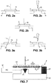
- the sample holder 4 carries a sealed membrane 5.
- the membrane 5 has no pores, and it is therefore here a method of forming a membrane.
- the beam 17 of liquid metal ions impacts at a given location of the membrane 5 so as to remove material, as shown in the figure 2b .
- the beam of metal ions having an energy of the order of tens of thousands of electron-Volts, focused at the level of the thin membrane on a fixed point (“point” mode) will produce a localized etching effect in the diaphragm.
- a common dose for this drilling mode is of the order of 10 18 to 10 20 ions/cm 2 .
- point is meant a focal spot of the smallest possible diameter attainable at the level of the sample holder.
- the dimensions of a focal spot are for example of the order of 10 nanometers.
- the detector 15 is connected to the central unit 16. At the level of the central unit, the signal received from detector 15 is compared with a predetermined threshold. Since the membrane 5 is sealed, the detector 15 detects nothing other than noise during this step. Thus, the signal level detected by the detector 15 is lower than the predetermined threshold.
- the central unit 16 is controlled so that, when the signal detected by the detector 15 exceeds said predetermined threshold, the erasing generator 18 diverts the beam 17 from the place where the pore is made, for example towards the stop electrode 24 ( figure 6a ).
- the erasing generator 18 diverts the beam 17 from the place where the pore is made, for example towards the stop electrode 24 ( figure 6a ).
- the subsequent use of the source 2 sees the metal ions pass through the pore 5, and a number of ions, even an electric current, are thus detected by the detector 15. Not all the metal ions pass through the pore 5, and the opening of this will increase during the use of the ion source, as well as the current detected. When this current reaches a predetermined threshold, the central unit 16 diverts the beam out of the sample holder 4.
- the threshold corresponds for example to the detection of a single ion from the beam 17 at the level of the detector 15.
- the etching time can then typically be of the order of 50 to 100 milliseconds (ms).
- the second mode as represented on the figures 3a to 3b , you can use the installation of the figure 1 to form an existing pore 19.
- a membrane 5 already provided with a pore 19 is provided on the sample holder 4.
- the detector 15 is used to detect the ions passing through the pore 19, and thus characterize this pore.
- the beam 17 irradiates an enlarged zone, for example of dimensions 100 nm ⁇ 100 nm around the pore, comprising locations 20 of the surface of the membrane 5 close to the pore 19, using of the scan generator 13. That is to say, the same source is used as in the drilling mode described above, the use differing mainly in that the characteristics of the scan generator 30 are changed rapidly.
- the dose can be reduced to values lower than the 'point' mode, for example of the order of 10 12 ions/cm 2 , which is insufficient to cause a significant removal of material (a a fortiori to create another pore).
- the irradiation by the charged particles coming from the source will create a diffusion of atoms from the membrane towards the nearby edges, c ie the ridges delimiting the pore.
- the material will aggregate there, thus closing the pore.
- the pore will thus be reduced by irradiation, by the beam, of locations near the pore.
- the opening of the pore can continue to be tested by using the beam 17 and by detecting the particles transmitted through the pore using the detector 15. Indeed, the trajectory mentioned above can cross the pore.
- the membrane is respected, by generating few mechanical vibrations in the membrane, by implanting few contaminating materials (Gallium) in the membrane.
- contaminating materials Gadium
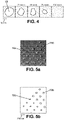
- the figure 4 represents five successive images of filling a pore using the object above. After having pierced a pore approximately 20 nm in diameter, as shown in the first thumbnail, the four other thumbnails represent the successive filling of this pore by irradiation of areas close to it, until a complete filling on the thumbnail on the right.
- the optics 3 can also be used to modify the energy of the ions on their arrival at the level of the sample holder.
- higher energy ions can be used in sputtering mode (digging a pore).
- spackling and imaging mode lower energy ions can be used, the detector detecting the charge of the ions passing through.
- the ions used in imaging mode if they do not cross, are less likely to affect the membrane.
- the material of the ion beam is undesirable in the membrane, provision may be made to remove it by suitable chemical attack.
- the process for creating a pore is successively implemented, as described above in relation to the figures 2a to 2c , and a filling process as described above with the figures 3a and 3b , so as to be able to generate a pore of perfectly desired size.
- This successive implementation is made using the same installation, the same source, for both processes.
- the source remains invariable, whether in drilling mode, filling mode, or for the detection of the transmitted current.
- the source emits a substantially constant current I, and particles of substantially constant energy in these different modes.
- the current I and the energy of the particles arriving at the level of the membrane are also kept constant in these different modes.
- the emission of the beam 17 can be generated for a predetermined time, based on experience, to obtain a certain filling of the pore.
- a pore is therefore obtained, the properties of which can be controlled (size (diameter, or average diameter), aspect ratio), the position in relation to electrodes (for measurement or control), and the environment (chemical, physiological ). Concerning the size, the smallest diameter will be considered transversely to the axis of the pore (axis normal to the surface of the membrane).
- the description which has been made above has been made for a pore.
- the pores can be realized as ordered networks in the membrane.
- the membrane having several pores can be used as it is, or can be cut with a view to several distinct parallel applications or uses.
- the detector 15 is movably mounted in the enclosure via a nanometric displacement system 23.
- This system 23 itself carries a micrometric displacement system 27 carrying the sample 4.
- sample 4 is formed as a thick slice comprising several independent membranes of dimension D of a few microns, and in each of which a pore is to be formed, and spaced from each other by a few hundred microns (dimension E of at least 10 microns ).
- the micrometric displacement system 27 is suitable for placing different membranes of the sample 4 successively under the beam. If necessary, a detection system such as system 14 can be used to check the exact position of the membrane with respect to the beam, and the optics 3 can be controlled to move the focal point in order to be sure that the beam is focused on the membrane.
- Such a system comprising a nanometric displacement system of a detector, and supporting a micrometric displacement system 27 can be integrated into a conventional focused ion beam emission machine, and could be marketed independently of the rest of the system. It then suffices to connect the detector 15 to the PC 16 to implement the above methods, in a controlled and repeated manner, for large numbers of membranes of the same sample.
Claims (17)
- Verfahren zum Bilden einer nanoporösen Membran, umfassend:- Bereitstellen eines Generators (100) eines lonenstrahls unter Verwendung einer Quelle (2) von Flüssigmetallionen, wobei die Quelle angepasst ist, um einen Strahl (17) geladener Spezies entlang einer optischen Achse (X) zu emittieren,- Bereitstellen eines Probenhalters (4), der eine Membran (5) gegenüber der Quelle entlang der optischen Achse trägt,- Bereitstellen eines Detektors (15) für geladene Teilchen stromabwärts von der Membran, wobei der Teilchendetektor angepasst ist, um eine Anzahl von Ionen zu bestimmen, die durch die Membran übertragen werden,- Steuern des Generators (100) eines lonenstrahls abhängig von der lonenzahl: in einem Durchdringungsmodus, Steuern des Generators (100) eines lonenstrahls abhängig von der lonenzahl, um eine Pore in die Membran einzuprägen, und- in einem Verschlussmodus, Steuern des Generators (100) eines lonenstrahls abhängig von der lonenzahl, um eine Pore der Membran zu verschließen, wobei mit dem Strahl auf einen Bereich gezielt wird, sodass die Atome der Membran, die schwach an ihre Oberfläche gebunden sind, diffundieren und an den scharfen Kanten der Membran eine Anhäufung von Atomen erzeugen,wobei der Strom und die Energie der an der Membran ankommenden Teilchen in diesen verschiedenen Modi konstant gehalten werden,wobei die Membran (4) eine Stärke von weniger als 100 Nanometern aufweist.
- Verfahren nach Anspruch 1, wobei der Detektor für geladene Teilchen (15) stromabwärts von der Membran entlang der optischen Achse bereitgestellt wird, wobei der Teilchendetektor angepasst ist, um eine Anzahl von Ionen zu erfassen, die durch die Membran übertragen werden.
- Verfahren nach einem der Ansprüche 1 bis 2, wobei beim Steuern des Generators eines lonenstrahls ein Verlauf des Strahls gesteuert wird.
- Verfahren nach Anspruch 3, wobei in dem Durchdringungsmodus der Generator (100) einen Strahl geladener Spezies auf einen Bereich der Membran abgibt, solange eine lonenzahl unterhalb eines vorbestimmten Schwellenwerts erfasst wird.
- Verfahren nach Anspruch 3 oder 4, wobei, wenn eine lonenzahl oberhalb eines vorbestimmten Schwellenwerts detektiert wird, der Strahl der geladenen Spezies aus dem Probenhalter abgelenkt wird.
- Verfahren nach Anspruch 3, wobei in dem Verschlussmodus der Generator (100) einen Strahl geladener Spezies auf einen erweiterten Bereich um die Pore herum abgibt, solange eine lonenzahl oberhalb eines vorbestimmten Schwellenwerts erfasst wird.
- Verfahren nach einem der vorherigen Ansprüche, wobei in dem Verschlussmodus die Pore (19) durch Bestrahlen der Membran um die Pore herum mit dem Strahl verschlossen wird.
- Verfahren nach einem der vorherigen Ansprüche, wobei in dem Verschlussmodus die Pore (19) verschlossen wird, indem ein ausgedehnter Flächenbereich der Membran um die Pore herum mit dem Strahl abgetastet wird.
- Verfahren nach einem der Ansprüche 1 bis 8, wobei beim Steuern des Generators eines lonenstrahls ein Bereich (20) eines Aufpralls des Strahl auf die Membran gesteuert wird.
- Verfahren nach einem der Ansprüche 1 bis 9, wobei die Membran (4) eine Stärke von weniger als 10 Nanometern aufweist.
- Verfahren nach einem der Ansprüche 1 bis 10, wobei die Membran (4) aus einem Material hergestellt ist, das aus der folgenden Liste ausgewählt ist: Siliziumkarbid, Siliziumoxid, Siliziumnitrid.
- Verfahren nach einem der Ansprüche 1 bis 11, wobei der Generator eines lonenstrahls gesteuert wird, indem das Öffnen und das Schließen einer elektrostatischen Klappe steuert, die zwischen der Quelle und dem Probenhalter angeordnet ist.
- Verfahren zum Bilden einer nanoporösen Membran nach einem der vorherigen Ansprüche, wobei ein zu erreichender Porendurchmesser (19) definiert wird und wobei der Durchdringungs- und der Verschlussmodus abwechselnd durchführt werden, bis eine Pore des genannten Durchmessers gebildet ist.
- Verfahren zum Bilden von nanoporösen Membranen, wobei die Schritte der Verfahren nach einem der Ansprüche 1 bis 13 für eine Vielzahl von Membranen einer selben Probe, wobei die Membranen mindestens 10 Mikrometer voneinander entfernt sind, oder für eine Vielzahl von Poren in einer Membran einer Probe, wobei die Poren mindestens 0,1 Mikrometer voneinander entfernt sind, wiederholt werden.
- Verfahren nach einem der vorherigen Ansprüche, wobei der lonenstrahl an dem Probenhalter in einem Bereich mit einstellbarem Durchmesser fokussiert wird, wobei der Durchmesser mindestens zwischen 10 Nanometern (nm) und 100 nm einstellbar ist.
- Anlage zum Bilden einer nanoporösen Membran, umfassend:- einen Generator (100) eines lonenstrahls unter Verwendung einer Quelle (2) von Flüssigmetallionen, wobei die Quelle angepasst ist, um einen Strahl (17) geladener Spezies entlang einer optischen Achse zu emittieren,- einen Probenhalter (4), der angepasst ist, um eine Membran gegenüber der Quelle entlang der optischen Achse zu tragen,- einen Detektor (15) für geladene Teilchen stromabwärts von der Membran, wobei der Teilchendetektor angepasst ist, um eine Anzahl von Ionen zu bestimmen, die durch die Membran übertragen werden, und- eine Zentraleinheit (16), die angepasst ist, um den Generator eines lonenstrahls abhängig von der genannten Anzahl von Ionen zu steuern, indem sie mit dem Strahl auf einen Bereich zielt,wobei die Zentraleinheit (16) angepasst ist, um Folgendes auszuwählen. einen Durchdringungsmodus, in dem der Generator (100) eines lonenstrahls abhängig von der genannten Anzahl von Ionen gesteuert wird, um eine Pore in die Membran zu einzuprägen, und. einen Verschlussmodus, in dem der Generator (100) eines lonenstrahls abhängig von der lonenzahl gesteuert wird, um den Generator eines lonenstrahls zu steuern, sodass er mit dem Strahl auf einen Bereich zielt, sodass die Atome der Membran, die schwach an ihre Oberfläche gebunden sind, gestreut werden und an den scharfen Kanten der Membran eine Ansammlung von Atomen erzeugt wird,wobei der Strom und die Energie der an der Membran ankommenden Teilchen in diesen verschiedenen Modi konstant gehalten werden,wobei die Membran eine Stärke von weniger als 100 Nanometern aufweist.
- Anlage nach Anspruch 16, wobei der Generator (100) eines lonenstrahls eine elektrostatische Optik (3) umfasst, umfassend mindestens eines von Folgenden:- einen Abtastgenerator (22), der angepasst ist, um den Strahl um eine Pore der Membran herum zu streuen,- einen Löschgenerator (18), der angepasst ist, um den Strahl aus dem Probenhalter abzulenken,- eine Linse (11, 12), die den lonenstrahl an dem Probenhalter in einem Bereich mit einstellbarem Durchmesser fokussiert, wobei der Durchmesser mindestens zwischen 10 Nanometern (nm) und 100 nm einstellbar ist.
Applications Claiming Priority (2)
| Application Number | Priority Date | Filing Date | Title |
|---|---|---|---|
| FR1257206A FR2993789B1 (fr) | 2012-07-25 | 2012-07-25 | Procede et installation de formation de membrane nano-poreuse. |
| PCT/FR2013/051752 WO2014016505A1 (fr) | 2012-07-25 | 2013-07-19 | Procede et installation de formation de membrane nano-poreuse |
Publications (2)
| Publication Number | Publication Date |
|---|---|
| EP2877273A1 EP2877273A1 (de) | 2015-06-03 |
| EP2877273B1 true EP2877273B1 (de) | 2022-10-26 |
Family
ID=47080700
Family Applications (1)
| Application Number | Title | Priority Date | Filing Date |
|---|---|---|---|
| EP13747467.2A Active EP2877273B1 (de) | 2012-07-25 | 2013-07-19 | Verfahren und vorrichtung zur herstellung einer nanoporösen membran |
Country Status (3)
| Country | Link |
|---|---|
| EP (1) | EP2877273B1 (de) |
| FR (1) | FR2993789B1 (de) |
| WO (1) | WO2014016505A1 (de) |
-
2012
- 2012-07-25 FR FR1257206A patent/FR2993789B1/fr active Active
-
2013
- 2013-07-19 WO PCT/FR2013/051752 patent/WO2014016505A1/fr active Application Filing
- 2013-07-19 EP EP13747467.2A patent/EP2877273B1/de active Active
Also Published As
| Publication number | Publication date |
|---|---|
| EP2877273A1 (de) | 2015-06-03 |
| WO2014016505A1 (fr) | 2014-01-30 |
| FR2993789A1 (fr) | 2014-01-31 |
| FR2993789B1 (fr) | 2019-06-28 |
Similar Documents
| Publication | Publication Date | Title |
|---|---|---|
| EP2836332B1 (de) | Vorrichtung uns verfahren zur nanoskaligen laserbearbeitung | |
| FR2849696A1 (fr) | Dispositif de fabrication de specimen et procede de fabrication de specimen | |
| EP2614363B1 (de) | Gerät zum kartieren und hochauflösender analyse von elementen in feststoffen | |
| FR2995439A1 (fr) | Source de rayons x generant un faisceau de taille nanometrique et dispositif d'imagerie comportant au moins une telle source | |
| FR3055970A1 (fr) | Methode de determination de la deflexion d'un faisceau d'electrons resultant d'un champ electrique et/ou d'un champ magnetique | |
| EP2877273B1 (de) | Verfahren und vorrichtung zur herstellung einer nanoporösen membran | |
| EP2297745A1 (de) | Einrichtung zum einfangen von teilchen | |
| EP2040875A2 (de) | Verfahren und vorrichtung zur bearbeitung eines ziels mit femtosekunden-laserstrahl | |
| EP1987530B1 (de) | Anlage und verfahren für nanoproduktion | |
| EP1699067B1 (de) | Verfahren zur Regelung eines Ionenstrahls | |
| EP2889602B1 (de) | Vorrichtung zur Charakterisierung von Teilchen in einem Teilchenstrahl in einem Vakuum | |
| EP2396806B1 (de) | Massenanalyseeinrichtung mit grosser winkelannahmefähigkeit mit einem reflektron | |
| EP2485249B1 (de) | Verfahren zum Glätten der Oberfläche eines Halbleiterwafers | |
| EP1490888B1 (de) | Einrichtung zur messung der emission von röntgenstrahlen, die durch ein objekt erzeugt werden, das einem elektronenstrahl ausgesetzt ist | |
| FR2903494A1 (fr) | Dispositif et procede de caracterisation de surfaces. notamment cristallines, a l'aide d'un faisceau d'atomes ou molecules neutres | |
| EP3203219B1 (de) | Verfahren zur charakterisierung einer probe mit hilfe einer kombination von röntgentomographie und sekundärionen-massenspektrometrie | |
| FR2832546A1 (fr) | Dispositif de reglage d'un appareil de generation d'un faisceau de particules chargees | |
| EP2219203B1 (de) | Verfahren zur Korrektur von Astigmatismus bei Bildgebungsverfahren durch Spektromikroskopie mit Elektronenemission | |
| EP3286533B1 (de) | Verfahren und vorrichtung zur charakterisierung eines hochleistungslaserstrahls | |
| WO2001065596A2 (fr) | Procede de controle de l'uniformite de traitement d'une surface de materiau pour la microelectronique par un faisceau de particules electriquement chargees et equipement de mise en oeuvre | |
| EP3994714A1 (de) | Gepulster generator von elektrisch geladenen teilchen und verfahren zur verwendung eines gepulsten generators von elektrisch geladenen teilchen | |
| WO2009065938A1 (fr) | Sonde atomique a haute acceptance | |
| FR3027399A1 (fr) | Appareil de sonde atomique tomographique et procede d'analyse d'un echantillon assistes par faisceau de particules, et utilisation d'un tel procede | |
| WO2011070306A1 (fr) | Procede et dispositif de transformation d'un faisceau laser a repartition d'energie gaussienne en faisceau laser a repartition uniforme d'energie | |
| FR3002684A1 (fr) | Procede de formation d'un motif dans un echantillon |
Legal Events
| Date | Code | Title | Description |
|---|---|---|---|
| PUAI | Public reference made under article 153(3) epc to a published international application that has entered the european phase |
Free format text: ORIGINAL CODE: 0009012 |
|
| 17P | Request for examination filed |
Effective date: 20150119 |
|
| AK | Designated contracting states |
Kind code of ref document: A1 Designated state(s): AL AT BE BG CH CY CZ DE DK EE ES FI FR GB GR HR HU IE IS IT LI LT LU LV MC MK MT NL NO PL PT RO RS SE SI SK SM TR |
|
| AX | Request for extension of the european patent |
Extension state: BA ME |
|
| DAX | Request for extension of the european patent (deleted) | ||
| STAA | Information on the status of an ep patent application or granted ep patent |
Free format text: STATUS: EXAMINATION IS IN PROGRESS |
|
| 17Q | First examination report despatched |
Effective date: 20170612 |
|
| STAA | Information on the status of an ep patent application or granted ep patent |
Free format text: STATUS: EXAMINATION IS IN PROGRESS |
|
| GRAP | Despatch of communication of intention to grant a patent |
Free format text: ORIGINAL CODE: EPIDOSNIGR1 |
|
| STAA | Information on the status of an ep patent application or granted ep patent |
Free format text: STATUS: GRANT OF PATENT IS INTENDED |
|
| RIC1 | Information provided on ipc code assigned before grant |
Ipc: B01D 61/02 20060101ALN20220411BHEP Ipc: B01D 71/02 20060101ALI20220411BHEP Ipc: H01J 37/305 20060101ALI20220411BHEP Ipc: H01J 37/244 20060101ALI20220411BHEP Ipc: B01D 67/00 20060101AFI20220411BHEP |
|
| INTG | Intention to grant announced |
Effective date: 20220517 |
|
| RIN1 | Information on inventor provided before grant (corrected) |
Inventor name: GIERAK, JACQUES |
|
| GRAS | Grant fee paid |
Free format text: ORIGINAL CODE: EPIDOSNIGR3 |
|
| GRAA | (expected) grant |
Free format text: ORIGINAL CODE: 0009210 |
|
| STAA | Information on the status of an ep patent application or granted ep patent |
Free format text: STATUS: THE PATENT HAS BEEN GRANTED |
|
| AK | Designated contracting states |
Kind code of ref document: B1 Designated state(s): AL AT BE BG CH CY CZ DE DK EE ES FI FR GB GR HR HU IE IS IT LI LT LU LV MC MK MT NL NO PL PT RO RS SE SI SK SM TR |
|
| REG | Reference to a national code |
Ref country code: GB Ref legal event code: FG4D Free format text: NOT ENGLISH |
|
| REG | Reference to a national code |
Ref country code: CH Ref legal event code: EP |
|
| REG | Reference to a national code |
Ref country code: DE Ref legal event code: R096 Ref document number: 602013082742 Country of ref document: DE |
|
| REG | Reference to a national code |
Ref country code: AT Ref legal event code: REF Ref document number: 1526654 Country of ref document: AT Kind code of ref document: T Effective date: 20221115 |
|
| REG | Reference to a national code |
Ref country code: IE Ref legal event code: FG4D Free format text: LANGUAGE OF EP DOCUMENT: FRENCH |
|
| REG | Reference to a national code |
Ref country code: LT Ref legal event code: MG9D |
|
| REG | Reference to a national code |
Ref country code: NL Ref legal event code: MP Effective date: 20221026 |
|
| REG | Reference to a national code |
Ref country code: AT Ref legal event code: MK05 Ref document number: 1526654 Country of ref document: AT Kind code of ref document: T Effective date: 20221026 |
|
| PG25 | Lapsed in a contracting state [announced via postgrant information from national office to epo] |
Ref country code: NL Free format text: LAPSE BECAUSE OF FAILURE TO SUBMIT A TRANSLATION OF THE DESCRIPTION OR TO PAY THE FEE WITHIN THE PRESCRIBED TIME-LIMIT Effective date: 20221026 |
|
| PG25 | Lapsed in a contracting state [announced via postgrant information from national office to epo] |
Ref country code: SE Free format text: LAPSE BECAUSE OF FAILURE TO SUBMIT A TRANSLATION OF THE DESCRIPTION OR TO PAY THE FEE WITHIN THE PRESCRIBED TIME-LIMIT Effective date: 20221026 Ref country code: PT Free format text: LAPSE BECAUSE OF FAILURE TO SUBMIT A TRANSLATION OF THE DESCRIPTION OR TO PAY THE FEE WITHIN THE PRESCRIBED TIME-LIMIT Effective date: 20230227 Ref country code: NO Free format text: LAPSE BECAUSE OF FAILURE TO SUBMIT A TRANSLATION OF THE DESCRIPTION OR TO PAY THE FEE WITHIN THE PRESCRIBED TIME-LIMIT Effective date: 20230126 Ref country code: LT Free format text: LAPSE BECAUSE OF FAILURE TO SUBMIT A TRANSLATION OF THE DESCRIPTION OR TO PAY THE FEE WITHIN THE PRESCRIBED TIME-LIMIT Effective date: 20221026 Ref country code: FI Free format text: LAPSE BECAUSE OF FAILURE TO SUBMIT A TRANSLATION OF THE DESCRIPTION OR TO PAY THE FEE WITHIN THE PRESCRIBED TIME-LIMIT Effective date: 20221026 Ref country code: ES Free format text: LAPSE BECAUSE OF FAILURE TO SUBMIT A TRANSLATION OF THE DESCRIPTION OR TO PAY THE FEE WITHIN THE PRESCRIBED TIME-LIMIT Effective date: 20221026 Ref country code: AT Free format text: LAPSE BECAUSE OF FAILURE TO SUBMIT A TRANSLATION OF THE DESCRIPTION OR TO PAY THE FEE WITHIN THE PRESCRIBED TIME-LIMIT Effective date: 20221026 |
|
| PG25 | Lapsed in a contracting state [announced via postgrant information from national office to epo] |
Ref country code: RS Free format text: LAPSE BECAUSE OF FAILURE TO SUBMIT A TRANSLATION OF THE DESCRIPTION OR TO PAY THE FEE WITHIN THE PRESCRIBED TIME-LIMIT Effective date: 20221026 Ref country code: PL Free format text: LAPSE BECAUSE OF FAILURE TO SUBMIT A TRANSLATION OF THE DESCRIPTION OR TO PAY THE FEE WITHIN THE PRESCRIBED TIME-LIMIT Effective date: 20221026 Ref country code: LV Free format text: LAPSE BECAUSE OF FAILURE TO SUBMIT A TRANSLATION OF THE DESCRIPTION OR TO PAY THE FEE WITHIN THE PRESCRIBED TIME-LIMIT Effective date: 20221026 Ref country code: IS Free format text: LAPSE BECAUSE OF FAILURE TO SUBMIT A TRANSLATION OF THE DESCRIPTION OR TO PAY THE FEE WITHIN THE PRESCRIBED TIME-LIMIT Effective date: 20230226 Ref country code: HR Free format text: LAPSE BECAUSE OF FAILURE TO SUBMIT A TRANSLATION OF THE DESCRIPTION OR TO PAY THE FEE WITHIN THE PRESCRIBED TIME-LIMIT Effective date: 20221026 Ref country code: GR Free format text: LAPSE BECAUSE OF FAILURE TO SUBMIT A TRANSLATION OF THE DESCRIPTION OR TO PAY THE FEE WITHIN THE PRESCRIBED TIME-LIMIT Effective date: 20230127 |
|
| REG | Reference to a national code |
Ref country code: DE Ref legal event code: R097 Ref document number: 602013082742 Country of ref document: DE |
|
| PG25 | Lapsed in a contracting state [announced via postgrant information from national office to epo] |
Ref country code: SM Free format text: LAPSE BECAUSE OF FAILURE TO SUBMIT A TRANSLATION OF THE DESCRIPTION OR TO PAY THE FEE WITHIN THE PRESCRIBED TIME-LIMIT Effective date: 20221026 Ref country code: RO Free format text: LAPSE BECAUSE OF FAILURE TO SUBMIT A TRANSLATION OF THE DESCRIPTION OR TO PAY THE FEE WITHIN THE PRESCRIBED TIME-LIMIT Effective date: 20221026 Ref country code: EE Free format text: LAPSE BECAUSE OF FAILURE TO SUBMIT A TRANSLATION OF THE DESCRIPTION OR TO PAY THE FEE WITHIN THE PRESCRIBED TIME-LIMIT Effective date: 20221026 Ref country code: DK Free format text: LAPSE BECAUSE OF FAILURE TO SUBMIT A TRANSLATION OF THE DESCRIPTION OR TO PAY THE FEE WITHIN THE PRESCRIBED TIME-LIMIT Effective date: 20221026 Ref country code: CZ Free format text: LAPSE BECAUSE OF FAILURE TO SUBMIT A TRANSLATION OF THE DESCRIPTION OR TO PAY THE FEE WITHIN THE PRESCRIBED TIME-LIMIT Effective date: 20221026 |
|
| PG25 | Lapsed in a contracting state [announced via postgrant information from national office to epo] |
Ref country code: SK Free format text: LAPSE BECAUSE OF FAILURE TO SUBMIT A TRANSLATION OF THE DESCRIPTION OR TO PAY THE FEE WITHIN THE PRESCRIBED TIME-LIMIT Effective date: 20221026 Ref country code: AL Free format text: LAPSE BECAUSE OF FAILURE TO SUBMIT A TRANSLATION OF THE DESCRIPTION OR TO PAY THE FEE WITHIN THE PRESCRIBED TIME-LIMIT Effective date: 20221026 |
|
| PLBE | No opposition filed within time limit |
Free format text: ORIGINAL CODE: 0009261 |
|
| STAA | Information on the status of an ep patent application or granted ep patent |
Free format text: STATUS: NO OPPOSITION FILED WITHIN TIME LIMIT |
|
| 26N | No opposition filed |
Effective date: 20230727 |
|
| PGFP | Annual fee paid to national office [announced via postgrant information from national office to epo] |
Ref country code: GB Payment date: 20230725 Year of fee payment: 11 |
|
| PG25 | Lapsed in a contracting state [announced via postgrant information from national office to epo] |
Ref country code: SI Free format text: LAPSE BECAUSE OF FAILURE TO SUBMIT A TRANSLATION OF THE DESCRIPTION OR TO PAY THE FEE WITHIN THE PRESCRIBED TIME-LIMIT Effective date: 20221026 |
|
| PGFP | Annual fee paid to national office [announced via postgrant information from national office to epo] |
Ref country code: FR Payment date: 20230727 Year of fee payment: 11 Ref country code: DE Payment date: 20230712 Year of fee payment: 11 |
|
| PG25 | Lapsed in a contracting state [announced via postgrant information from national office to epo] |
Ref country code: MC Free format text: LAPSE BECAUSE OF FAILURE TO SUBMIT A TRANSLATION OF THE DESCRIPTION OR TO PAY THE FEE WITHIN THE PRESCRIBED TIME-LIMIT Effective date: 20221026 |
|
| PG25 | Lapsed in a contracting state [announced via postgrant information from national office to epo] |
Ref country code: MC Free format text: LAPSE BECAUSE OF FAILURE TO SUBMIT A TRANSLATION OF THE DESCRIPTION OR TO PAY THE FEE WITHIN THE PRESCRIBED TIME-LIMIT Effective date: 20221026 |
|
| REG | Reference to a national code |
Ref country code: CH Ref legal event code: PL |
|
| REG | Reference to a national code |
Ref country code: BE Ref legal event code: MM Effective date: 20230731 |
|
| PG25 | Lapsed in a contracting state [announced via postgrant information from national office to epo] |
Ref country code: LU Free format text: LAPSE BECAUSE OF NON-PAYMENT OF DUE FEES Effective date: 20230719 |
|
| PG25 | Lapsed in a contracting state [announced via postgrant information from national office to epo] |
Ref country code: LU Free format text: LAPSE BECAUSE OF NON-PAYMENT OF DUE FEES Effective date: 20230719 |