EP2877273B1 - Method and apparatus for forming a nanoporous membrane - Google Patents
Method and apparatus for forming a nanoporous membrane Download PDFInfo
- Publication number
- EP2877273B1 EP2877273B1 EP13747467.2A EP13747467A EP2877273B1 EP 2877273 B1 EP2877273 B1 EP 2877273B1 EP 13747467 A EP13747467 A EP 13747467A EP 2877273 B1 EP2877273 B1 EP 2877273B1
- Authority
- EP
- European Patent Office
- Prior art keywords
- membrane
- pore
- ions
- ion beam
- generator
- Prior art date
- Legal status (The legal status is an assumption and is not a legal conclusion. Google has not performed a legal analysis and makes no representation as to the accuracy of the status listed.)
- Active
Links
- 239000012528 membrane Substances 0.000 title claims description 114
- 238000000034 method Methods 0.000 title claims description 32
- 239000011148 porous material Substances 0.000 claims description 87
- 150000002500 ions Chemical class 0.000 claims description 66
- 238000010884 ion-beam technique Methods 0.000 claims description 38
- 239000002245 particle Substances 0.000 claims description 26
- 239000000463 material Substances 0.000 claims description 10
- 230000003287 optical effect Effects 0.000 claims description 10
- 229910001338 liquidmetal Inorganic materials 0.000 claims description 7
- 229910052581 Si3N4 Inorganic materials 0.000 claims description 3
- VYPSYNLAJGMNEJ-UHFFFAOYSA-N Silicium dioxide Chemical compound O=[Si]=O VYPSYNLAJGMNEJ-UHFFFAOYSA-N 0.000 claims description 3
- 238000004220 aggregation Methods 0.000 claims description 3
- 230000002776 aggregation Effects 0.000 claims description 3
- HBMJWWWQQXIZIP-UHFFFAOYSA-N silicon carbide Chemical compound [Si+]#[C-] HBMJWWWQQXIZIP-UHFFFAOYSA-N 0.000 claims description 3
- 229910010271 silicon carbide Inorganic materials 0.000 claims description 3
- HQVNEWCFYHHQES-UHFFFAOYSA-N silicon nitride Chemical compound N12[Si]34N5[Si]62N3[Si]51N64 HQVNEWCFYHHQES-UHFFFAOYSA-N 0.000 claims description 3
- 229910052814 silicon oxide Inorganic materials 0.000 claims description 3
- 230000015572 biosynthetic process Effects 0.000 claims description 2
- 230000001678 irradiating effect Effects 0.000 claims description 2
- 230000008685 targeting Effects 0.000 claims 1
- 238000009434 installation Methods 0.000 description 19
- 230000008569 process Effects 0.000 description 10
- 238000005553 drilling Methods 0.000 description 6
- 238000001514 detection method Methods 0.000 description 5
- 238000006073 displacement reaction Methods 0.000 description 5
- 238000004519 manufacturing process Methods 0.000 description 5
- 238000005530 etching Methods 0.000 description 4
- 229910052751 metal Inorganic materials 0.000 description 4
- 239000002184 metal Substances 0.000 description 4
- XUIMIQQOPSSXEZ-UHFFFAOYSA-N Silicon Chemical compound [Si] XUIMIQQOPSSXEZ-UHFFFAOYSA-N 0.000 description 3
- 229910021645 metal ion Inorganic materials 0.000 description 3
- 239000011163 secondary particle Substances 0.000 description 3
- 239000000126 substance Substances 0.000 description 3
- 101100536354 Drosophila melanogaster tant gene Proteins 0.000 description 2
- GYHNNYVSQQEPJS-UHFFFAOYSA-N Gallium Chemical compound [Ga] GYHNNYVSQQEPJS-UHFFFAOYSA-N 0.000 description 2
- 238000009792 diffusion process Methods 0.000 description 2
- 230000000694 effects Effects 0.000 description 2
- 230000003628 erosive effect Effects 0.000 description 2
- 229910052733 gallium Inorganic materials 0.000 description 2
- 238000003384 imaging method Methods 0.000 description 2
- 230000007246 mechanism Effects 0.000 description 2
- 238000007493 shaping process Methods 0.000 description 2
- 229910001020 Au alloy Inorganic materials 0.000 description 1
- 238000013459 approach Methods 0.000 description 1
- 230000005493 condensed matter Effects 0.000 description 1
- 239000000470 constituent Substances 0.000 description 1
- 238000011109 contamination Methods 0.000 description 1
- 239000002178 crystalline material Substances 0.000 description 1
- 230000006866 deterioration Effects 0.000 description 1
- 238000010586 diagram Methods 0.000 description 1
- 230000005684 electric field Effects 0.000 description 1
- 238000001493 electron microscopy Methods 0.000 description 1
- 238000001962 electrophoresis Methods 0.000 description 1
- 238000005429 filling process Methods 0.000 description 1
- 239000010408 film Substances 0.000 description 1
- 239000011888 foil Substances 0.000 description 1
- 239000003353 gold alloy Substances 0.000 description 1
- 238000012625 in-situ measurement Methods 0.000 description 1
- 230000010354 integration Effects 0.000 description 1
- 230000003993 interaction Effects 0.000 description 1
- 229920002521 macromolecule Polymers 0.000 description 1
- 238000005259 measurement Methods 0.000 description 1
- 238000005459 micromachining Methods 0.000 description 1
- 150000004767 nitrides Chemical class 0.000 description 1
- 230000000149 penetrating effect Effects 0.000 description 1
- 238000012545 processing Methods 0.000 description 1
- 230000000644 propagated effect Effects 0.000 description 1
- 238000012552 review Methods 0.000 description 1
- 238000004544 sputter deposition Methods 0.000 description 1
- 239000000758 substrate Substances 0.000 description 1
- 239000010409 thin film Substances 0.000 description 1
Images


Classifications
-
- B—PERFORMING OPERATIONS; TRANSPORTING
- B01—PHYSICAL OR CHEMICAL PROCESSES OR APPARATUS IN GENERAL
- B01D—SEPARATION
- B01D71/00—Semi-permeable membranes for separation processes or apparatus characterised by the material; Manufacturing processes specially adapted therefor
- B01D71/02—Inorganic material
- B01D71/0215—Silicon carbide; Silicon nitride; Silicon oxycarbide
-
- H—ELECTRICITY
- H01—ELECTRIC ELEMENTS
- H01J—ELECTRIC DISCHARGE TUBES OR DISCHARGE LAMPS
- H01J37/00—Discharge tubes with provision for introducing objects or material to be exposed to the discharge, e.g. for the purpose of examination or processing thereof
- H01J37/02—Details
- H01J37/244—Detectors; Associated components or circuits therefor
-
- B—PERFORMING OPERATIONS; TRANSPORTING
- B01—PHYSICAL OR CHEMICAL PROCESSES OR APPARATUS IN GENERAL
- B01D—SEPARATION
- B01D67/00—Processes specially adapted for manufacturing semi-permeable membranes for separation processes or apparatus
- B01D67/0039—Inorganic membrane manufacture
- B01D67/0053—Inorganic membrane manufacture by inducing porosity into non porous precursor membranes
- B01D67/006—Inorganic membrane manufacture by inducing porosity into non porous precursor membranes by elimination of segments of the precursor, e.g. nucleation-track membranes, lithography or laser methods
-
- B—PERFORMING OPERATIONS; TRANSPORTING
- B01—PHYSICAL OR CHEMICAL PROCESSES OR APPARATUS IN GENERAL
- B01D—SEPARATION
- B01D71/00—Semi-permeable membranes for separation processes or apparatus characterised by the material; Manufacturing processes specially adapted therefor
- B01D71/02—Inorganic material
-
- H—ELECTRICITY
- H01—ELECTRIC ELEMENTS
- H01J—ELECTRIC DISCHARGE TUBES OR DISCHARGE LAMPS
- H01J37/00—Discharge tubes with provision for introducing objects or material to be exposed to the discharge, e.g. for the purpose of examination or processing thereof
- H01J37/30—Electron-beam or ion-beam tubes for localised treatment of objects
- H01J37/305—Electron-beam or ion-beam tubes for localised treatment of objects for casting, melting, evaporating or etching
- H01J37/3053—Electron-beam or ion-beam tubes for localised treatment of objects for casting, melting, evaporating or etching for evaporating or etching
- H01J37/3056—Electron-beam or ion-beam tubes for localised treatment of objects for casting, melting, evaporating or etching for evaporating or etching for microworking, e.g. etching of gratings, trimming of electrical components
-
- B—PERFORMING OPERATIONS; TRANSPORTING
- B01—PHYSICAL OR CHEMICAL PROCESSES OR APPARATUS IN GENERAL
- B01D—SEPARATION
- B01D2323/00—Details relating to membrane preparation
- B01D2323/34—Use of radiation
-
- B—PERFORMING OPERATIONS; TRANSPORTING
- B01—PHYSICAL OR CHEMICAL PROCESSES OR APPARATUS IN GENERAL
- B01D—SEPARATION
- B01D61/00—Processes of separation using semi-permeable membranes, e.g. dialysis, osmosis or ultrafiltration; Apparatus, accessories or auxiliary operations specially adapted therefor
- B01D61/02—Reverse osmosis; Hyperfiltration ; Nanofiltration
- B01D61/027—Nanofiltration
-
- H—ELECTRICITY
- H01—ELECTRIC ELEMENTS
- H01J—ELECTRIC DISCHARGE TUBES OR DISCHARGE LAMPS
- H01J2237/00—Discharge tubes exposing object to beam, e.g. for analysis treatment, etching, imaging
- H01J2237/244—Detection characterized by the detecting means
- H01J2237/24455—Transmitted particle detectors
-
- H—ELECTRICITY
- H01—ELECTRIC ELEMENTS
- H01J—ELECTRIC DISCHARGE TUBES OR DISCHARGE LAMPS
- H01J2237/00—Discharge tubes exposing object to beam, e.g. for analysis treatment, etching, imaging
- H01J2237/30—Electron or ion beam tubes for processing objects
- H01J2237/317—Processing objects on a microscale
- H01J2237/31749—Focused ion beam
Definitions
- the present invention relates to processes and installations for forming nano-porous membranes.
- the object of the present invention is in particular to provide such manufacture.
- the invention relates to an installation for forming a nanoporous membrane according to claim 16.
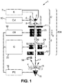
- the figure 1 represents an installation 1 suitable for the implementation of a nanoporous membrane treatment method.
- One architecture of such an installation takes up that of a focused ion beam (FIB, for “focused ion beam”) emission column. It comprises in particular an ion beam generator 100 fitted with a source 2 and an optic 3.
- the installation also comprises a sample holder 4 carrying a sample 5.
- the source, the optics and the sample holder are arranged one after the other, in this order, along an X axis of the generator.
- the source is a liquid metal ion source (LMIS, for “liquid metal ion source”). It comprises a tip 6 electrically connected to a generator 7. The generator supplies tip 6 with a voltage making it possible to polarize the tip.
- the tip is made with a core, for example of a metal refractory, carrying a continuous layer of metal on its surface.
- the metal for example gallium, or a gold alloy, or other, is for example also contained in a reservoir 8 from which it flows towards the end of the tip.
- the ion source 2 also comprises an extractor electrode 9 which can be powered by a dedicated generator 10, in order to generate a potential difference between an extractor electrode 9 and the tip 6. This potential difference generates an electric field which is capable of to extract liquid metal ions, or clusters of these ions from the tip 6.
- the ions thus extracted are propagated in a beam 17 generally in the direction of the sample holder 4 along the axis X.
- the optics 3 comprises a series of lenses suitable for shaping the ion beam. Note in particular a lens 11, close to the source 2, suitable for shaping the ion beam, and an object lens 12 close to the sample holder 4, suitable for concentrating the ion beam in the direction of the sample holder. sample 4.
- a scanning device 13 is provided to spread the ion beam over a given area of the sample holder 4.
- This scanning generator 22 comprises one or more electrodes 13 suitable for electrically influencing the charged particles passing nearby, to deviate their trajectory, in a manner changing over time, in the direction of given points of the sample holder 4.
- the scanning device 13 makes it possible to spread the beam over an area of the membrane , of large surface area relative to the diameter of the pore, for example of the order of 100 nm ⁇ 100 nm.
- the installation also comprises a beam erasing system comprising a series of electrostatic deflectors 25, for example located close to the source 2, and a stop electrode 24, located downstream of the lenses 25, and comprising a through opening 26 of small diameter.
- a beam erasing system constitutes an electrostatic gate for the beam, the “open” or “closed” states of which can be controlled at will.
- the erase generator 18 can power the electrodes 25 so as to cause the beam 17 to pass through the aperture 26 (as shown), or to direct it towards the stop electrode 24.
- the generator 18 is for example a fast bistable voltage generator, allowing a rise or fall time of less than a microsecond.
- the sample holder 4 carries a membrane 5 to be formed.
- the membrane 5 is for example made up of a thin film of mechanically resistant material, such as a silicon carbide, oxide or nitride, or the like. It is for example a non-crystalline film.
- An example of a constituent material is Si 3 N 4 .
- the membrane 5 is 100 nm thick, in particular less than 25 nm thick, or even less than 10 nm thick.
- a detector 15 is used located downstream of the sample holder 4 along the X axis. Thus, the sample holder 4 is arranged between the source 2 and the detector 15.
- a particle detector is used, suitable for detecting particles, in particular electrically charged particles, flowing from the source: the charged ions or clusters coming from the source 2.
- a particle detector a detector capable of detect the low signal levels expected with such ion sources. It is, for example, a detector of the channeltron type, or multichannel plates.
- the installation 1 also comprises a central unit 16 connected to the detector 15.
- the central unit 16 is capable of determining the number of particles detected by the detector 15.
- a secondary particle detector 15 arranged off the optical axis, and placed opposite the upper face (that facing the source 2) of a target placed downstream of the sample holder 4, and detecting so-called secondary electrons, projected from the target due to the arrival thereon of charged particles from source 2.
- the number of charged particles crossing the membrane can be determined, indirectly, from the measured signal by the secondary electron detector.
- the rest of the description refers to the embodiment using the downstream detector 15 of the direct type arranged along the optical axis.
- the central unit 16 is also capable of controlling the arrival of the beam 17 at the level of the sample holder 4.
- the central unit 16 is connected to the scanning generator 13.
- the central unit 16 is capable of comparing the number of particles detected by the detector 15 with a predetermined threshold level, and, according to this comparison, of influencing the arrival of the beam 17 at the level of the sample holder 4.
- the sample holder 4 carries a sealed membrane 5.
- the membrane 5 has no pores, and it is therefore here a method of forming a membrane.
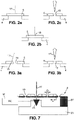
- the beam 17 of liquid metal ions impacts at a given location of the membrane 5 so as to remove material, as shown in the figure 2b .
- the beam of metal ions having an energy of the order of tens of thousands of electron-Volts, focused at the level of the thin membrane on a fixed point (“point” mode) will produce a localized etching effect in the diaphragm.
- a common dose for this drilling mode is of the order of 10 18 to 10 20 ions/cm 2 .
- point is meant a focal spot of the smallest possible diameter attainable at the level of the sample holder.
- the dimensions of a focal spot are for example of the order of 10 nanometers.
- the detector 15 is connected to the central unit 16. At the level of the central unit, the signal received from detector 15 is compared with a predetermined threshold. Since the membrane 5 is sealed, the detector 15 detects nothing other than noise during this step. Thus, the signal level detected by the detector 15 is lower than the predetermined threshold.
- the central unit 16 is controlled so that, when the signal detected by the detector 15 exceeds said predetermined threshold, the erasing generator 18 diverts the beam 17 from the place where the pore is made, for example towards the stop electrode 24 ( figure 6a ).
- the erasing generator 18 diverts the beam 17 from the place where the pore is made, for example towards the stop electrode 24 ( figure 6a ).
- the subsequent use of the source 2 sees the metal ions pass through the pore 5, and a number of ions, even an electric current, are thus detected by the detector 15. Not all the metal ions pass through the pore 5, and the opening of this will increase during the use of the ion source, as well as the current detected. When this current reaches a predetermined threshold, the central unit 16 diverts the beam out of the sample holder 4.
- the threshold corresponds for example to the detection of a single ion from the beam 17 at the level of the detector 15.
- the etching time can then typically be of the order of 50 to 100 milliseconds (ms).
- the second mode as represented on the figures 3a to 3b , you can use the installation of the figure 1 to form an existing pore 19.
- a membrane 5 already provided with a pore 19 is provided on the sample holder 4.
- the detector 15 is used to detect the ions passing through the pore 19, and thus characterize this pore.
- the beam 17 irradiates an enlarged zone, for example of dimensions 100 nm ⁇ 100 nm around the pore, comprising locations 20 of the surface of the membrane 5 close to the pore 19, using of the scan generator 13. That is to say, the same source is used as in the drilling mode described above, the use differing mainly in that the characteristics of the scan generator 30 are changed rapidly.
- the dose can be reduced to values lower than the 'point' mode, for example of the order of 10 12 ions/cm 2 , which is insufficient to cause a significant removal of material (a a fortiori to create another pore).
- the irradiation by the charged particles coming from the source will create a diffusion of atoms from the membrane towards the nearby edges, c ie the ridges delimiting the pore.
- the material will aggregate there, thus closing the pore.
- the pore will thus be reduced by irradiation, by the beam, of locations near the pore.
- the opening of the pore can continue to be tested by using the beam 17 and by detecting the particles transmitted through the pore using the detector 15. Indeed, the trajectory mentioned above can cross the pore.
- the membrane is respected, by generating few mechanical vibrations in the membrane, by implanting few contaminating materials (Gallium) in the membrane.
- contaminating materials Gadium
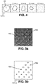
- the figure 4 represents five successive images of filling a pore using the object above. After having pierced a pore approximately 20 nm in diameter, as shown in the first thumbnail, the four other thumbnails represent the successive filling of this pore by irradiation of areas close to it, until a complete filling on the thumbnail on the right.
- the optics 3 can also be used to modify the energy of the ions on their arrival at the level of the sample holder.
- higher energy ions can be used in sputtering mode (digging a pore).
- spackling and imaging mode lower energy ions can be used, the detector detecting the charge of the ions passing through.
- the ions used in imaging mode if they do not cross, are less likely to affect the membrane.
- the material of the ion beam is undesirable in the membrane, provision may be made to remove it by suitable chemical attack.
- the process for creating a pore is successively implemented, as described above in relation to the figures 2a to 2c , and a filling process as described above with the figures 3a and 3b , so as to be able to generate a pore of perfectly desired size.
- This successive implementation is made using the same installation, the same source, for both processes.
- the source remains invariable, whether in drilling mode, filling mode, or for the detection of the transmitted current.
- the source emits a substantially constant current I, and particles of substantially constant energy in these different modes.
- the current I and the energy of the particles arriving at the level of the membrane are also kept constant in these different modes.
- the emission of the beam 17 can be generated for a predetermined time, based on experience, to obtain a certain filling of the pore.
- a pore is therefore obtained, the properties of which can be controlled (size (diameter, or average diameter), aspect ratio), the position in relation to electrodes (for measurement or control), and the environment (chemical, physiological ). Concerning the size, the smallest diameter will be considered transversely to the axis of the pore (axis normal to the surface of the membrane).
- the description which has been made above has been made for a pore.
- the pores can be realized as ordered networks in the membrane.
- the membrane having several pores can be used as it is, or can be cut with a view to several distinct parallel applications or uses.
- the detector 15 is movably mounted in the enclosure via a nanometric displacement system 23.
- This system 23 itself carries a micrometric displacement system 27 carrying the sample 4.
- sample 4 is formed as a thick slice comprising several independent membranes of dimension D of a few microns, and in each of which a pore is to be formed, and spaced from each other by a few hundred microns (dimension E of at least 10 microns ).
- the micrometric displacement system 27 is suitable for placing different membranes of the sample 4 successively under the beam. If necessary, a detection system such as system 14 can be used to check the exact position of the membrane with respect to the beam, and the optics 3 can be controlled to move the focal point in order to be sure that the beam is focused on the membrane.
- Such a system comprising a nanometric displacement system of a detector, and supporting a micrometric displacement system 27 can be integrated into a conventional focused ion beam emission machine, and could be marketed independently of the rest of the system. It then suffices to connect the detector 15 to the PC 16 to implement the above methods, in a controlled and repeated manner, for large numbers of membranes of the same sample.
Description
La présente invention est relative aux procédés et aux installations de formation de membranes nano-poreuses.The present invention relates to processes and installations for forming nano-porous membranes.
Plus particulièrement, l'invention se rapporte à un procédé de formation d'une membrane nano-poreuse comprenant :
- on fournit un générateur de faisceau d'ions utilisant une source d'ions de métal liquide, la source étant adaptée pour émettre un faisceau d'espèces chargées selon un axe optique,
- on fournit un porte-échantillon portant une membrane en regard de la source le long de l'axe optique.
- an ion beam generator is provided using a source of liquid metal ions, the source being adapted to emit a beam of charged species along an optical axis,
- a sample holder carrying a membrane facing the source along the optical axis is provided.
Le document
De tels procédés de gravure sont également décrits dans les documents
Par ailleurs,
La fabrication simple, économique, reproductible, de pores présentant de manière contrôlée des caractéristiques variables (notamment taille et matériau du substrat variables) constitue aujourd'hui un défi, pour s'adapter à une demande toujours croissante de membranes nano-poreuses.The simple, economical, reproducible manufacture of pores having variable characteristics in a controlled manner (in particular variable size and material of the substrate) today constitutes a challenge, in order to adapt to an ever-increasing demand for nano-porous membranes.
Par exemple,
La présente invention a notamment pour but de fournir une telle fabrication.The object of the present invention is in particular to provide such manufacture.
A cet effet, selon l'invention, un procédé du genre en question est défini dans la revendication 1.To this end, according to the invention, a method of the kind in question is defined in
Grâce à ces dispositions, on obtient un pore dont on peut contrôler les propriétés.Thanks to these arrangements, a pore is obtained, the properties of which can be controlled.
Dans des modes de réalisation préférés de l'invention, on peut éventuellement avoir recours en outre à l'une et/ou à l'autre des dispositions suivantes :
- on fournit le détecteur de particules chargées en aval de la membrane le long de l'axe optique, le détecteur de particules étant adapté pour détecter un nombre d'ions transmis à travers la membrane ;
- on focalise le faisceau d'ions au niveau du porte-échantillon en une zone de diamètre réglable, le diamètre étant réglable au moins entre 10 et 100 nanomètres ;
- on met en œuvre le mode de perçage au cours duquel le générateur émet un faisceau d'ions de formation d'un pore dans la membrane, et on détecte un nombre d'ions transmis à travers le pore,
on met en œuvre le mode de rebouchage au cours duquel le générateur émet un faisceau d'ions de rebouchage d'un pore ; - lorsqu'on contrôle le générateur de faisceau d'ions, on contrôle un trajet dudit faisceau ;
- dans le mode de perçage, tant qu'on détecte un nombre d'ions inférieur à un seuil prédéterminé, le générateur délivre un faisceau d'espèces chargées sur une zone de la membrane [Dans ce mode perçage, la zone est assimilée à un point fixe de dimensions faibles - de l'ordre de 10 nanomètres par exemple ; Le courant d'ions I est concentré sur une surface de superficie Sp de sorte que le rapport I/S est suffisamment élevé pour produire un effet de gravure intense (I/Sp par exemple de l'ordre de 1018 ions/cm2)];
- lorsqu'on détecte un nombre d'ions supérieur à un seuil prédéterminé, on divertit le faisceau d'espèces chargées en dehors du porte-échantillon ;
- dans le mode de rebouchage, tant qu'on détecte un nombre d'ions supérieur à un seuil prédéterminé, le générateur délivre un faisceau d'espèces chargées sur une zone élargie autour du pore;
- dans le mode de rebouchage, on rebouche le pore par irradiation de la membrane autour du pore avec ledit faisceau [Dans ce mode rebouchage, la zone irradiée est de dimensions élevées ; Un balayage du faisceau permet d'augmenter la superficie de la surface Sr de la zone de la membrane irradiée par le faisceau autour du pore de plusieurs ordres de grandeur par rapport au mode perçage, de sorte que le rapport I/Sr soit réduit à une valeur très faible par rapport à I/Sp (I/Sr par exemple de l'ordre de 1012 ions/cm2)] ;
- dans le mode de rebouchage, on rebouche le pore en balayant une zone de superficie étendue de la membrane autour du pore avec ledit faisceau ;
- lorsqu'on contrôle le générateur de faisceau d'ions, on contrôle une zone d'impact du faisceau sur la membrane ;
- la membrane a une épaisseur inférieure à 10 nanomètres, et/ou est réalisée en un matériau choisi dans la liste suivante : carbure de silicium, oxyde de silicium, nitride de silicium ;
- on contrôle le générateur de faisceau d'ions en commandant l'ouverture et la fermeture d'une porte électrostatique disposée entre la source et le porte-échantillon ;
- on définit un diamètre de pore à atteindre, et on alterne les modes de perçage et de rebouchage jusqu'à former un pore dudit diamètre ;
- on reproduit lesdites étapes pour une pluralité de membranes d'un même échantillon, les membranes étant espacées les unes des autres d'au moins 10 microns, ou pour une pluralité de pores dans une membrane d'un échantillon, les pores étant espacés les uns des autres d'au moins 0.1 micron.
- providing the charged particle detector downstream of the membrane along the optical axis, the particle detector being adapted to detect a number of ions transmitted through the membrane;
- the ion beam is focused at the level of the sample holder in a zone of adjustable diameter, the diameter being adjustable at least between 10 and 100 nanometers;
- the drilling mode is implemented during which the generator emits a beam of ions to form a pore in the membrane, and a number of ions transmitted through the pore is detected,
the filling mode is implemented during which the generator emits a beam of filling ions from a pore; - when controlling the ion beam generator, controlling a path of said beam;
- in piercing mode, as long as a number of ions below a predetermined threshold is detected, the generator delivers a beam of charged species to an area of the membrane [In this piercing mode, the area is likened to a point stationary of small dimensions - of the order of 10 nanometers for example; The current of ions I is concentrated on a surface with an area S p so that the I/S ratio is high enough to produce an intense etching effect (I/S p for example of the order of 10 18 ions/cm 2 )];
- when a number of ions greater than a predetermined threshold is detected, the beam of charged species is diverted outside the sample holder;
- in the filling mode, as long as a number of ions greater than a predetermined threshold is detected, the generator delivers a beam of charged species over a widened zone around the pore;
- in the plugging mode, the pore is plugged by irradiating the membrane around the pore with said beam [In this plugging mode, the irradiated zone is of large dimensions; A scan of the beam makes it possible to increase the surface area S r of the zone of the membrane irradiated by the beam around the pore by several orders of magnitude compared to the drilling mode, so that the ratio I/S r is reduced at a very low value relative to I/S p (I/S r for example of the order of 10 12 ions/cm 2 )];
- in the plugging mode, the pore is plugged by scanning an area of extended surface area of the membrane around the pore with said beam;
- when the ion beam generator is controlled, a zone of impact of the beam on the membrane is controlled;
- the membrane has a thickness of less than 10 nanometers, and/or is made of a material chosen from the following list: silicon carbide, silicon oxide, silicon nitride;
- the ion beam generator is controlled by controlling the opening and closing of an electrostatic gate arranged between the source and the sample holder;
- a pore diameter to be achieved is defined, and the drilling and filling modes are alternated until a pore of said diameter is formed;
- said steps are repeated for a plurality of membranes of the same sample, the membranes being spaced apart from each other by at least 10 microns, or for a plurality of pores in a membrane of a sample, the pores being spaced apart another of at least 0.1 micron.
Selon un autre aspect, l'invention se rapporte à une installation de formation d'une membrane nanoporeuse selon la revendication 16.According to another aspect, the invention relates to an installation for forming a nanoporous membrane according to
Selon un mode particulier, le générateur de faisceau d'ions comprend une optique électrostatique comprenant également :
- un générateur de balayage adapté pour disperser le faisceau autour d'un pore de la membrane ; et/ou
- un générateur d'effacement adapté pour divertir le faisceau hors du porte-échantillon, et/ou
- une lentille focalisant le faisceau d'ions au niveau du porte-échantillon en une zone de diamètre réglable, le diamètre étant réglable au moins entre 10 et 100 nanomètres.
- a scanning generator adapted to disperse the beam around a pore of the membrane; and or
- an erasure generator adapted to divert the beam out of the sample holder, and/or
- a lens focusing the ion beam at the level of the sample holder in an area of adjustable diameter, the diameter being adjustable at least between 10 and 100 nanometers.
D'autres caractéristiques et avantages de l'invention apparaîtront au cours de la description suivante de deux de ses formes de réalisation, donnée à titre d'exemple non limitatif, en regard des dessins joints.Other characteristics and advantages of the invention will become apparent during the following description of two of its embodiments, given by way of non-limiting example, with reference to the appended drawings.
Sur les dessins :
- la
figure 1 est une vue schématique d'une installation convenant pour la mise en œuvre du procédé, - les
figures 2a, 2b et 2c sont des vues schématiques de la membrane à différentes étapes dans une première utilisation de l'installation de lafigure 1 , - les
figures 3a, 3b sont des vues similaires auxfigures 2a à 2c , pour un deuxième mode d'utilisation de cette installation, - la
figure 4 est une vue schématique d'un échantillon à différentes étapes, - les
figures 5a et 5b sont des vues de dessus d'une membrane comportant plusieurs pores (respectivement vue microscopique et schéma illustratif), - les
figures 6a et6b sont deux vues similaires à lafigure 1 de deux modes d'utilisation de l'installation, et - la
figure 7 montre un système multi-membranes.
- the
figure 1 is a schematic view of a installation suitable for implementing the process, - them
figures 2a, 2b and 2c are schematic views of the membrane at various stages in a first use of the installation of thefigure 1 , - them
figures 3a, 3b are views similar tofigures 2a to 2c , for a second mode of use of this installation, - the
figure 4 is a schematic view of a sample at different stages, - them
figures 5a and 5b are top views of a membrane with several pores (respectively microscopic view and illustrative diagram), - them
figures 6a and6b are two views similar to thefigure 1 two modes of use of the installation, and - the
figure 7 shows a multi-membrane system.
Sur les différentes figures, les mêmes références désignent des éléments identiques ou similaires.In the various figures, the same references designate identical or similar elements.
La
La source est une source d'ions de métal liquide (LMIS, pour « liquid metal ion source »). Elle comporte une pointe 6 reliée électriquement à un générateur 7. Le générateur fournit à la pointe 6 une tension permettant de polariser la pointe. La pointe est réalisée comportant un noyau, par exemple d'un métal réfractaire, portant une couche continue de métal à sa surface. Le métal, par exemple du gallium, ou un alliage d'or, ou autre, est par exemple également contenu dans un réservoir 8 à partir duquel il s'écoule vers l'extrémité de la pointe. La source d'ions 2 comprend également une électrode extractrice 9 qui peut être alimentée par un générateur dédié 10, afin de générer une différence de potentiel entre une électrode extractrice 9 et la pointe 6. Cette différence de potentiel génère un champ électrique qui est apte à arracher des ions de métal liquide, ou des amas de ces ions de la pointe 6. Les ions ainsi arrachés sont propagés en un faisceau 17 globalement en direction du porte échantillon 4 le long de l'axe X.The source is a liquid metal ion source (LMIS, for “liquid metal ion source”). It comprises a
L'optique 3 comprend une série de lentilles adaptées pour mettre en forme le faisceau d'ions. On notera en particulier une lentille 11, proche de la source 2, adaptée pour mettre en forme le faisceau d'ions, et une lentille objet 12 proche du porte-échantillon 4, adaptée pour concentrer le faisceau d'ions en direction du porte-échantillon 4.The
Entre les lentilles 11 et 12, on prévoit un dispositif de balayage 13 pour étaler le faisceau d'ions sur une zone donnée du porte-échantillon 4. Ce générateur de balayage 22 comprend une ou plusieurs électrodes 13 adaptées pour influencer électriquement sur les particules chargées passant à proximité, pour dévier leur trajectoire, de manière changeant dans le temps, en direction de points donnés du porte-échantillon 4. Lorsqu'il est activé, le dispositif de balayage 13 permet d'étaler le faisceau sur une zone de la membrane, de superficie grande par rapport au diamètre du pore, par exemple de l'ordre de 100 nm x 100 nm.Between the
L'installation comprend également un système d'effacement de faisceau comprenant une série de déflecteurs électrostatiques 25, par exemple situées proche de la source 2, et une électrode d'arrêt 24, située en aval des lentilles 25, et comportant une ouverture traversante 26 de faible diamètre. Un tel système d'effacement constitue une porte électrostatique pour le faisceau, dont on peut contrôler à volonté les états « ouvert » ou « fermé ». Le générateur 18 d'effacement peut alimenter les électrodes 25 de manière à faire passer le faisceau 17 au travers de l'ouverture 26 (tel que représenté), ou de diriger celui-ci vers l'électrode d'arrêt 24.The installation also comprises a beam erasing system comprising a series of
Le générateur 18 est par exemple un générateur de tension bistable rapide, permettant un temps de montée ou de descente inférieur à la micro-seconde.The
Dans le cas présent, le porte-échantillon 4 porte une membrane 5 à former. La membrane 5 est par exemple constituée d'un mince film de matériau résistant mécaniquement, tels qu'un carbure, oxyde ou nitrure de silicium, ou autre. Il s'agit par exemple d'un film non cristallin. Un exemple de matériau constitutif est Si3N4. La membrane 5 fait 100 nm d'épaisseur, en particulier moins de 25 nm d'épaisseur, voire moins de 10 nm d'épaisseur.In the present case, the
On peut utiliser également un détecteur 14 de particules secondaires. Ces particules secondaires sont des particules, notamment chargées, pulvérisées de la membrane 5 à l'arrivée du faisceau d'ions en provenance de la source 2.It is also possible to use a
On utilise un détecteur 15 situé en aval du porte échantillon 4 le long de l'axe X. Ainsi, le porte échantillon 4 est disposé entre la source 2 et le détecteur 15. À titre de détecteur 15, on utilise un détecteur de particules, adapté pour détecter des particules, notamment chargées électriquement, s'écoulant depuis la source : les ions ou amas chargés provenant de la source 2. À titre de détecteur de particules, on utilise un détecteur capable de détecter les faibles niveaux de signal attendu avec de telles sources d'ions. Il s'agit, par exemple, d'un détecteur de type channeltron, ou plaques multicanaux.A
L'installation 1 comprend également une unité centrale 16 reliée au détecteur 15. L'unité centrale 16 est capable de déterminer le nombre de particules détectées par le détecteur 15.The
En variante, on pourrait utiliser un détecteur 15 de particules secondaires disposé hors de l'axe optique, et placé en regard de la face supérieure (celle tournée vers la source 2) d'une cible placée en aval du porte-échantillon 4, et détectant des électrons, dits secondaires, projetés depuis la cible du fait de l'arrivée sur celle-ci des particules chargées en provenance de la source 2. Le nombre de particules chargées traversant la membrane peut être déterminé, indirectement, à partir du signal mesuré par le détecteur d'électrons secondaires. La suite de la description fait référence au mode de réalisation utilisant le détecteur aval 15 de type direct disposé le long de l'axe optique.As a variant, one could use a
L'unité centrale 16 est également capable de commander l'arrivée du faisceau 17 au niveau du porte échantillon 4. À titre d'exemple, l'unité centrale 16 est reliée au générateur de balayage 13. Ainsi, l'unité centrale 16 est capable de comparer le nombre de particules détectées par le détecteur 15 avec un niveau de seuil prédéterminé, et, en fonction de cette comparaison, d'influer sur l'arrivée du faisceau 17 au niveau du porte échantillon 4.The
Deux exemples de mise en œuvre d'une telle installation vont être décrits ci-après, les deux exemples faisant correspondance aux deux modes des revendications indépendantes 1 et 16.Two examples of implementation of such an installation will be described below, the two examples corresponding to the two modes of
Dans un premier exemple, le premier mode, représenté aux
Le seuil correspond par exemple à la détection d'un unique ion du faisceau 17 au niveau du détecteur 15. Le temps de gravure peut alors typiquement être de l'ordre de 50 à 100 millisecondes (ms).The threshold corresponds for example to the detection of a single ion from the
Selon le deuxième mode, comme représenté sur les
En utilisant le procédé ci-dessus pour le bouchage du pore, on respecte la membrane, en générant peu de vibrations mécaniques dans la membrane, en implantant peu de matériaux contaminants (Gallium) dans la membrane. En utilisant une membrane en matériau non cristallin, on génère également peu de dégâts dans la membrane.By using the above process for plugging the pore, the membrane is respected, by generating few mechanical vibrations in the membrane, by implanting few contaminating materials (Gallium) in the membrane. By using a membrane of non-crystalline material, little damage is also generated in the membrane.
Ainsi, la
L'optique 3 peut également être utilisée pour modifier l'énergie des ions à leur arrivée au niveau du porte-échantillon. Ainsi, en mode pulvérisation (creuser un pore), on peut utiliser des ions de plus haute énergie. En mode de rebouchage et d'imagerie, on peut utiliser des ions d'énergie plus faible, le détecteur détectant la charge des ions traversant. Ainsi, les ions utilisés en mode d'imagerie, s'ils ne traversent pas, risquent moins d'affecter la membrane.The
Si le matériau du faisceau d'ions est indésirable dans la membrane, on pourra prévoir de l'enlever par une attaque chimique adaptée.If the material of the ion beam is undesirable in the membrane, provision may be made to remove it by suitable chemical attack.
De plus, on met en œuvre successivement le procédé de création d'un pore, tels que décrit ci-dessus en relation avec les
La description qui a été faite ci-dessus a été faite pour un pore. Toutefois, on pourra, avec le même outil, aisément réaliser la même opération successivement pour plusieurs pores, comme représenté en
Un tel système comprenant un système de déplacement nanométrique d'un détecteur, et supportant un système de déplacement micrométrique 27 peut être intégré dans une machine d'émission de faisceau d'ions focalisés classique, et pourrait être commercialisé indépendamment du reste du système. Il suffit alors de connecter le détecteur 15 au PC 16 pour mettre en œuvre les procédés ci-dessus, de manière contrôlée et répétée, pour de grands nombres de membranes d'un même échantillon.Such a system comprising a nanometric displacement system of a detector, and supporting a
Claims (17)
- A method of forming a nano-porous membrane comprising:- an ion beam generator (100) is provided using a liquid metal ion source (2), the source being adapted to emit a beam (17) of charged species along an optical axis (X),- a sample holder (4) is provided carrying a membrane (5) facing the source along the optical axis,- a charged particle detector (15) is provided downstream of the membrane, the particle detector being adapted to determine a number of ions transmitted through the membrane,- the ion beam generator (100) is controlled in accordance with said number of ions: In a piercing mode, the ion beam generator (100) is controlled in accordance with said number of ions to etch a pore in the membrane and- in a recapping mode, the ion beam generator (100) is controlled in accordance with said number of ions to recap a pore of the membrane, aiming at an area with the beam so as to diffuse weakly bound atoms of the membrane to its surface and create an aggregation of atoms at the sharp edges of the membrane,the current and energy of the particles arriving at the membrane being kept constant in these different modes,the membrane (4) having a thickness of less than 100 nanometres.
- The method according to claim 1, wherein the charged particle detector (15) is provided downstream of the membrane along the optical axis, the particle detector being adapted to detect a number of ions transmitted through the membrane.
- The method according to any of claims 1 to 2 wherein, when the ion beam generator is controlled, a path of said beam is controlled.
- The method according to claim 3, wherein in the piercing mode, as long as a number of ions below a predetermined threshold is detected, the generator (100) delivers a beam of charged species to an area of the membrane.
- The method according to claim 3 or 4, wherein, when a number of ions above a predetermined threshold is detected, the beam of charged species is diverted from the sample holder.
- The method according to claim 3, wherein in the recapping mode, as long as a number of ions above a predetermined threshold is detected, the generator (100) delivers a beam of charged species to an expanded area of the membrane.
- The method according to any of the preceding claims, wherein, in the recapping mode, the pore (19) is recapped by irradiating the membrane around the pore with said beam.
- The method according to any of the preceding claims, wherein, in the recapping mode, the pore (19) is recapped by scanning an expanded surface area of the membrane around the pore with said beam.
- The method according to any of claims 1 to 8 wherein, when the ion beam generator is controlled, an area (20) of beam impingement on the membrane is controlled.
- The method according to any of claims 1 to 9, wherein the membrane (4) has a thickness of less than 10 nanometers.
- The method according to any of claims 1 to 10, wherein the membrane (4) is made of a material selected from the following list: silicon carbide, silicon oxide, silicon nitride.
- The method according to any of claims 1 to 11, wherein the ion beam generator is controlled by controlling the opening and closing of an electrostatic gate disposed between the source and the sample holder.
- The method of forming a nano-porous membrane according to one of the preceding claims, in which a pore diameter (19) to be achieved is defined, and in which the piercing and recapping modes are alternated until a pore of said diameter is formed.
- The method of forming nano-porous membranes, wherein the steps of the methods according to any one of claims 1 to 13 are reproduced for a plurality of membranes in a given sample, the membranes being spaced apart by at least ten microns, or for a plurality of pores in a membrane in a sample, the pores being spaced apart by at least 0.1 microns.
- The method according to any one of the preceding claims, wherein the ion beam is focused at the sample holder into an area of adjustable diameter, the diameter being adjustable to at least between 10 nanometers (nm) and 100 nm.
- A nanoporous membrane formation system comprising:- an ion beam generator (100) using a liquid metal ion source (2), the source being adapted to emit a beam (17) of charged species along an optical axis (X),- a sample holder (4) adapted to carry a membrane facing the source along the optical axis,- a charged particle detector (15) downstream of the membrane, the particle detector being adapted to determine a number of ions transmitted through the membrane, and- a central unit (16) adapted to control the ion beam generator in accordance with said number of ions, by targeting an area with the beamin which the central unit (16) is adapted to select. a piercing mode, in which the ion beam generator (100) is controlled in accordance with said number of ions to etch a pore into the membrane, and. a recapping mode, the ion beam generator (100) is controlled in accordance with said number of ions to control the ion beam generator by aiming at an area with the beam so as to diffuse weakly bound atoms of the membrane to its surface and create an aggregation of atoms at the sharp edges of the membrane,the current and energy of the particles arriving at the membrane being kept constant in these different modes,the membrane having a thickness of less than 100 nanometres.
- A system according to claim 16 wherein the ion beam generator (100) comprises an electrostatic optic (3) comprising at least one of:- a scan generator (22) adapted to disperse the beam around a pore of the membrane,- an erasure generator (18) adapted to divert the beam from the sample holder,- a lens (11, 12) focusing the ion beam at the sample holder to an area of adjustable diameter, the diameter being adjustable to at least between 10 nanometres (nm) and 100 nm.
Applications Claiming Priority (2)
| Application Number | Priority Date | Filing Date | Title |
|---|---|---|---|
| FR1257206A FR2993789B1 (en) | 2012-07-25 | 2012-07-25 | METHOD AND INSTALLATION OF NANO-POROUS MEMBRANE FORMATION |
| PCT/FR2013/051752 WO2014016505A1 (en) | 2012-07-25 | 2013-07-19 | Method and apparatus for forming a nanoporous membrane |
Publications (2)
| Publication Number | Publication Date |
|---|---|
| EP2877273A1 EP2877273A1 (en) | 2015-06-03 |
| EP2877273B1 true EP2877273B1 (en) | 2022-10-26 |
Family
ID=47080700
Family Applications (1)
| Application Number | Title | Priority Date | Filing Date |
|---|---|---|---|
| EP13747467.2A Active EP2877273B1 (en) | 2012-07-25 | 2013-07-19 | Method and apparatus for forming a nanoporous membrane |
Country Status (3)
| Country | Link |
|---|---|
| EP (1) | EP2877273B1 (en) |
| FR (1) | FR2993789B1 (en) |
| WO (1) | WO2014016505A1 (en) |
-
2012
- 2012-07-25 FR FR1257206A patent/FR2993789B1/en active Active
-
2013
- 2013-07-19 EP EP13747467.2A patent/EP2877273B1/en active Active
- 2013-07-19 WO PCT/FR2013/051752 patent/WO2014016505A1/en active Application Filing
Also Published As
| Publication number | Publication date |
|---|---|
| FR2993789B1 (en) | 2019-06-28 |
| WO2014016505A1 (en) | 2014-01-30 |
| FR2993789A1 (en) | 2014-01-31 |
| EP2877273A1 (en) | 2015-06-03 |
Similar Documents
| Publication | Publication Date | Title |
|---|---|---|
| EP2836332B1 (en) | Device and method for nano-scale laser machining | |
| FR2849696A1 (en) | SPECIMEN MANUFACTURING DEVICE AND SPECIMEN MANUFACTURING METHOD | |
| EP2614363B1 (en) | Apparatus for mapping and high resolution analysis of elements in solids | |
| FR2995439A1 (en) | X-RAY SOURCE GENERATING A NANOMETRIC SIZE BEAM AND IMAGING DEVICE COMPRISING AT LEAST ONE SUCH SOURCE | |
| FR3055970A1 (en) | METHOD FOR DETERMINING THE DEFLECTION OF AN ELECTRON BEAM RESULTING FROM AN ELECTRIC FIELD AND / OR A MAGNETIC FIELD | |
| EP2877273B1 (en) | Method and apparatus for forming a nanoporous membrane | |
| WO2009144187A1 (en) | Device for trapping particles | |
| EP2040875A2 (en) | Method and device for machining a target using a femtosecond laser beam | |
| EP1987530B1 (en) | Nanofabrication installation and process | |
| EP1699067B1 (en) | Method of controlling an ion beam | |
| EP2889602B1 (en) | Device for characterising particles in a particle stream under vacuum | |
| EP2396806B1 (en) | Mass analysis device with wide angular acceptance including a reflectron | |
| FR2903494A1 (en) | DEVICE AND METHOD FOR CHARACTERIZING SURFACES. PARTICULARLY CRYSTALLINE, USING A BEAM OF NEUTRAL ATOMS OR MOLECULES | |
| EP3203219B1 (en) | Method for characterising a sample combining x-ray tomography with secondary ion mass spectrometry | |
| FR2832546A1 (en) | Device for adjusting an apparatus for generating a beam of charged particles | |
| EP1490888B1 (en) | Device for measuring the emission of x rays produced by an object exposed to an electron beam | |
| EP2219203B1 (en) | Method for correcting astigmatism using electron-emitting spectromicroscopic imaging | |
| EP3286533B1 (en) | Method and device for characterizing a high-power laser beam | |
| WO2001065596A2 (en) | Method for controlling uniformity of treatment of a surface of material for microelectronics with an electrically charged particle beam and equipment therefor | |
| EP3994714A1 (en) | Pulsed generator of electrically charged particles and method of use of a pulsed generator of electrically charged particles | |
| WO2009065938A1 (en) | Atom probe with a high acceptance | |
| FR3027399A1 (en) | TOMOGRAPHIC ATOMIC PROBE APPARATUS AND PARTICLE BEAM ASSISTED SAMPLE ANALYZED METHOD, AND USE OF SUCH A METHOD | |
| WO2011070306A1 (en) | Method and device for converting a laser beam with gaussian power distribution into a laser beam with uniform power distribution | |
| FR3002684A1 (en) | METHOD FOR FORMING A PATTERN IN A SAMPLE | |
| FR2823008A1 (en) | Transistor nanostructure ion beam adjustment process having test shaped formed using digital reference pattern, then original image compared and adjustment made/process continued until good match obtained |
Legal Events
| Date | Code | Title | Description |
|---|---|---|---|
| PUAI | Public reference made under article 153(3) epc to a published international application that has entered the european phase |
Free format text: ORIGINAL CODE: 0009012 |
|
| 17P | Request for examination filed |
Effective date: 20150119 |
|
| AK | Designated contracting states |
Kind code of ref document: A1 Designated state(s): AL AT BE BG CH CY CZ DE DK EE ES FI FR GB GR HR HU IE IS IT LI LT LU LV MC MK MT NL NO PL PT RO RS SE SI SK SM TR |
|
| AX | Request for extension of the european patent |
Extension state: BA ME |
|
| DAX | Request for extension of the european patent (deleted) | ||
| STAA | Information on the status of an ep patent application or granted ep patent |
Free format text: STATUS: EXAMINATION IS IN PROGRESS |
|
| 17Q | First examination report despatched |
Effective date: 20170612 |
|
| STAA | Information on the status of an ep patent application or granted ep patent |
Free format text: STATUS: EXAMINATION IS IN PROGRESS |
|
| GRAP | Despatch of communication of intention to grant a patent |
Free format text: ORIGINAL CODE: EPIDOSNIGR1 |
|
| STAA | Information on the status of an ep patent application or granted ep patent |
Free format text: STATUS: GRANT OF PATENT IS INTENDED |
|
| RIC1 | Information provided on ipc code assigned before grant |
Ipc: B01D 61/02 20060101ALN20220411BHEP Ipc: B01D 71/02 20060101ALI20220411BHEP Ipc: H01J 37/305 20060101ALI20220411BHEP Ipc: H01J 37/244 20060101ALI20220411BHEP Ipc: B01D 67/00 20060101AFI20220411BHEP |
|
| INTG | Intention to grant announced |
Effective date: 20220517 |
|
| RIN1 | Information on inventor provided before grant (corrected) |
Inventor name: GIERAK, JACQUES |
|
| GRAS | Grant fee paid |
Free format text: ORIGINAL CODE: EPIDOSNIGR3 |
|
| GRAA | (expected) grant |
Free format text: ORIGINAL CODE: 0009210 |
|
| STAA | Information on the status of an ep patent application or granted ep patent |
Free format text: STATUS: THE PATENT HAS BEEN GRANTED |
|
| AK | Designated contracting states |
Kind code of ref document: B1 Designated state(s): AL AT BE BG CH CY CZ DE DK EE ES FI FR GB GR HR HU IE IS IT LI LT LU LV MC MK MT NL NO PL PT RO RS SE SI SK SM TR |
|
| REG | Reference to a national code |
Ref country code: GB Ref legal event code: FG4D Free format text: NOT ENGLISH |
|
| REG | Reference to a national code |
Ref country code: CH Ref legal event code: EP |
|
| REG | Reference to a national code |
Ref country code: DE Ref legal event code: R096 Ref document number: 602013082742 Country of ref document: DE |
|
| REG | Reference to a national code |
Ref country code: AT Ref legal event code: REF Ref document number: 1526654 Country of ref document: AT Kind code of ref document: T Effective date: 20221115 |
|
| REG | Reference to a national code |
Ref country code: IE Ref legal event code: FG4D Free format text: LANGUAGE OF EP DOCUMENT: FRENCH |
|
| REG | Reference to a national code |
Ref country code: LT Ref legal event code: MG9D |
|
| REG | Reference to a national code |
Ref country code: NL Ref legal event code: MP Effective date: 20221026 |
|
| REG | Reference to a national code |
Ref country code: AT Ref legal event code: MK05 Ref document number: 1526654 Country of ref document: AT Kind code of ref document: T Effective date: 20221026 |
|
| PG25 | Lapsed in a contracting state [announced via postgrant information from national office to epo] |
Ref country code: NL Free format text: LAPSE BECAUSE OF FAILURE TO SUBMIT A TRANSLATION OF THE DESCRIPTION OR TO PAY THE FEE WITHIN THE PRESCRIBED TIME-LIMIT Effective date: 20221026 |
|
| PG25 | Lapsed in a contracting state [announced via postgrant information from national office to epo] |
Ref country code: SE Free format text: LAPSE BECAUSE OF FAILURE TO SUBMIT A TRANSLATION OF THE DESCRIPTION OR TO PAY THE FEE WITHIN THE PRESCRIBED TIME-LIMIT Effective date: 20221026 Ref country code: PT Free format text: LAPSE BECAUSE OF FAILURE TO SUBMIT A TRANSLATION OF THE DESCRIPTION OR TO PAY THE FEE WITHIN THE PRESCRIBED TIME-LIMIT Effective date: 20230227 Ref country code: NO Free format text: LAPSE BECAUSE OF FAILURE TO SUBMIT A TRANSLATION OF THE DESCRIPTION OR TO PAY THE FEE WITHIN THE PRESCRIBED TIME-LIMIT Effective date: 20230126 Ref country code: LT Free format text: LAPSE BECAUSE OF FAILURE TO SUBMIT A TRANSLATION OF THE DESCRIPTION OR TO PAY THE FEE WITHIN THE PRESCRIBED TIME-LIMIT Effective date: 20221026 Ref country code: FI Free format text: LAPSE BECAUSE OF FAILURE TO SUBMIT A TRANSLATION OF THE DESCRIPTION OR TO PAY THE FEE WITHIN THE PRESCRIBED TIME-LIMIT Effective date: 20221026 Ref country code: ES Free format text: LAPSE BECAUSE OF FAILURE TO SUBMIT A TRANSLATION OF THE DESCRIPTION OR TO PAY THE FEE WITHIN THE PRESCRIBED TIME-LIMIT Effective date: 20221026 Ref country code: AT Free format text: LAPSE BECAUSE OF FAILURE TO SUBMIT A TRANSLATION OF THE DESCRIPTION OR TO PAY THE FEE WITHIN THE PRESCRIBED TIME-LIMIT Effective date: 20221026 |
|
| PG25 | Lapsed in a contracting state [announced via postgrant information from national office to epo] |
Ref country code: RS Free format text: LAPSE BECAUSE OF FAILURE TO SUBMIT A TRANSLATION OF THE DESCRIPTION OR TO PAY THE FEE WITHIN THE PRESCRIBED TIME-LIMIT Effective date: 20221026 Ref country code: PL Free format text: LAPSE BECAUSE OF FAILURE TO SUBMIT A TRANSLATION OF THE DESCRIPTION OR TO PAY THE FEE WITHIN THE PRESCRIBED TIME-LIMIT Effective date: 20221026 Ref country code: LV Free format text: LAPSE BECAUSE OF FAILURE TO SUBMIT A TRANSLATION OF THE DESCRIPTION OR TO PAY THE FEE WITHIN THE PRESCRIBED TIME-LIMIT Effective date: 20221026 Ref country code: IS Free format text: LAPSE BECAUSE OF FAILURE TO SUBMIT A TRANSLATION OF THE DESCRIPTION OR TO PAY THE FEE WITHIN THE PRESCRIBED TIME-LIMIT Effective date: 20230226 Ref country code: HR Free format text: LAPSE BECAUSE OF FAILURE TO SUBMIT A TRANSLATION OF THE DESCRIPTION OR TO PAY THE FEE WITHIN THE PRESCRIBED TIME-LIMIT Effective date: 20221026 Ref country code: GR Free format text: LAPSE BECAUSE OF FAILURE TO SUBMIT A TRANSLATION OF THE DESCRIPTION OR TO PAY THE FEE WITHIN THE PRESCRIBED TIME-LIMIT Effective date: 20230127 |
|
| REG | Reference to a national code |
Ref country code: DE Ref legal event code: R097 Ref document number: 602013082742 Country of ref document: DE |
|
| PG25 | Lapsed in a contracting state [announced via postgrant information from national office to epo] |
Ref country code: SM Free format text: LAPSE BECAUSE OF FAILURE TO SUBMIT A TRANSLATION OF THE DESCRIPTION OR TO PAY THE FEE WITHIN THE PRESCRIBED TIME-LIMIT Effective date: 20221026 Ref country code: RO Free format text: LAPSE BECAUSE OF FAILURE TO SUBMIT A TRANSLATION OF THE DESCRIPTION OR TO PAY THE FEE WITHIN THE PRESCRIBED TIME-LIMIT Effective date: 20221026 Ref country code: EE Free format text: LAPSE BECAUSE OF FAILURE TO SUBMIT A TRANSLATION OF THE DESCRIPTION OR TO PAY THE FEE WITHIN THE PRESCRIBED TIME-LIMIT Effective date: 20221026 Ref country code: DK Free format text: LAPSE BECAUSE OF FAILURE TO SUBMIT A TRANSLATION OF THE DESCRIPTION OR TO PAY THE FEE WITHIN THE PRESCRIBED TIME-LIMIT Effective date: 20221026 Ref country code: CZ Free format text: LAPSE BECAUSE OF FAILURE TO SUBMIT A TRANSLATION OF THE DESCRIPTION OR TO PAY THE FEE WITHIN THE PRESCRIBED TIME-LIMIT Effective date: 20221026 |
|
| PG25 | Lapsed in a contracting state [announced via postgrant information from national office to epo] |
Ref country code: SK Free format text: LAPSE BECAUSE OF FAILURE TO SUBMIT A TRANSLATION OF THE DESCRIPTION OR TO PAY THE FEE WITHIN THE PRESCRIBED TIME-LIMIT Effective date: 20221026 Ref country code: AL Free format text: LAPSE BECAUSE OF FAILURE TO SUBMIT A TRANSLATION OF THE DESCRIPTION OR TO PAY THE FEE WITHIN THE PRESCRIBED TIME-LIMIT Effective date: 20221026 |
|
| PLBE | No opposition filed within time limit |
Free format text: ORIGINAL CODE: 0009261 |
|
| STAA | Information on the status of an ep patent application or granted ep patent |
Free format text: STATUS: NO OPPOSITION FILED WITHIN TIME LIMIT |
|
| 26N | No opposition filed |
Effective date: 20230727 |
|
| PGFP | Annual fee paid to national office [announced via postgrant information from national office to epo] |
Ref country code: GB Payment date: 20230725 Year of fee payment: 11 |
|
| PG25 | Lapsed in a contracting state [announced via postgrant information from national office to epo] |
Ref country code: SI Free format text: LAPSE BECAUSE OF FAILURE TO SUBMIT A TRANSLATION OF THE DESCRIPTION OR TO PAY THE FEE WITHIN THE PRESCRIBED TIME-LIMIT Effective date: 20221026 |
|
| PGFP | Annual fee paid to national office [announced via postgrant information from national office to epo] |
Ref country code: FR Payment date: 20230727 Year of fee payment: 11 Ref country code: DE Payment date: 20230712 Year of fee payment: 11 |
|
| PG25 | Lapsed in a contracting state [announced via postgrant information from national office to epo] |
Ref country code: MC Free format text: LAPSE BECAUSE OF FAILURE TO SUBMIT A TRANSLATION OF THE DESCRIPTION OR TO PAY THE FEE WITHIN THE PRESCRIBED TIME-LIMIT Effective date: 20221026 |
|
| PG25 | Lapsed in a contracting state [announced via postgrant information from national office to epo] |
Ref country code: MC Free format text: LAPSE BECAUSE OF FAILURE TO SUBMIT A TRANSLATION OF THE DESCRIPTION OR TO PAY THE FEE WITHIN THE PRESCRIBED TIME-LIMIT Effective date: 20221026 |
|
| REG | Reference to a national code |
Ref country code: CH Ref legal event code: PL |
|
| PG25 | Lapsed in a contracting state [announced via postgrant information from national office to epo] |
Ref country code: LU Free format text: LAPSE BECAUSE OF NON-PAYMENT OF DUE FEES Effective date: 20230719 |
|
| PG25 | Lapsed in a contracting state [announced via postgrant information from national office to epo] |
Ref country code: LU Free format text: LAPSE BECAUSE OF NON-PAYMENT OF DUE FEES Effective date: 20230719 |