EP2877251B1 - Rope grab - Google Patents
Rope grab Download PDFInfo
- Publication number
- EP2877251B1 EP2877251B1 EP13742361.2A EP13742361A EP2877251B1 EP 2877251 B1 EP2877251 B1 EP 2877251B1 EP 13742361 A EP13742361 A EP 13742361A EP 2877251 B1 EP2877251 B1 EP 2877251B1
- Authority
- EP
- European Patent Office
- Prior art keywords
- housing
- side plate
- elongated member
- passage
- rope grab
- Prior art date
- Legal status (The legal status is an assumption and is not a legal conclusion. Google has not performed a legal analysis and makes no representation as to the accuracy of the status listed.)
- Active
Links
- 125000006850 spacer group Chemical group 0.000 claims description 30
- 230000003068 static effect Effects 0.000 claims description 10
- 210000005069 ears Anatomy 0.000 claims description 7
- 230000005484 gravity Effects 0.000 claims description 7
- 238000000034 method Methods 0.000 claims description 5
- 230000036961 partial effect Effects 0.000 description 14
- 239000006096 absorbing agent Substances 0.000 description 10
- 230000009194 climbing Effects 0.000 description 7
- 230000004913 activation Effects 0.000 description 4
- 208000027418 Wounds and injury Diseases 0.000 description 3
- 230000006378 damage Effects 0.000 description 3
- 208000014674 injury Diseases 0.000 description 3
- 230000000717 retained effect Effects 0.000 description 3
- 238000010276 construction Methods 0.000 description 2
- KJLPSBMDOIVXSN-UHFFFAOYSA-N 4-[4-[2-[4-(3,4-dicarboxyphenoxy)phenyl]propan-2-yl]phenoxy]phthalic acid Chemical compound C=1C=C(OC=2C=C(C(C(O)=O)=CC=2)C(O)=O)C=CC=1C(C)(C)C(C=C1)=CC=C1OC1=CC=C(C(O)=O)C(C(O)=O)=C1 KJLPSBMDOIVXSN-UHFFFAOYSA-N 0.000 description 1
- 230000006978 adaptation Effects 0.000 description 1
- 230000002452 interceptive effect Effects 0.000 description 1
- 230000000670 limiting effect Effects 0.000 description 1
Images


Classifications
-
- A—HUMAN NECESSITIES
- A62—LIFE-SAVING; FIRE-FIGHTING
- A62B—DEVICES, APPARATUS OR METHODS FOR LIFE-SAVING
- A62B35/00—Safety belts or body harnesses; Similar equipment for limiting displacement of the human body, especially in case of sudden changes of motion
- A62B35/0081—Equipment which can travel along the length of a lifeline, e.g. travelers
-
- A—HUMAN NECESSITIES
- A62—LIFE-SAVING; FIRE-FIGHTING
- A62B—DEVICES, APPARATUS OR METHODS FOR LIFE-SAVING
- A62B1/00—Devices for lowering persons from buildings or the like
- A62B1/06—Devices for lowering persons from buildings or the like by making use of rope-lowering devices
- A62B1/14—Devices for lowering persons from buildings or the like by making use of rope-lowering devices with brakes sliding on the rope
-
- A—HUMAN NECESSITIES
- A62—LIFE-SAVING; FIRE-FIGHTING
- A62B—DEVICES, APPARATUS OR METHODS FOR LIFE-SAVING
- A62B35/00—Safety belts or body harnesses; Similar equipment for limiting displacement of the human body, especially in case of sudden changes of motion
- A62B35/0043—Lifelines, lanyards, and anchors therefore
- A62B35/005—Vertical lifelines
-
- A—HUMAN NECESSITIES
- A62—LIFE-SAVING; FIRE-FIGHTING
- A62B—DEVICES, APPARATUS OR METHODS FOR LIFE-SAVING
- A62B35/00—Safety belts or body harnesses; Similar equipment for limiting displacement of the human body, especially in case of sudden changes of motion
- A62B35/04—Safety belts or body harnesses; Similar equipment for limiting displacement of the human body, especially in case of sudden changes of motion incorporating energy absorbing means
Definitions
- a rope grab in one embodiment, includes a housing, a locking cam, a cam biasing member and a locking arm.
- the housing has an elongated member guide forming an elongated member passage.
- the elongated member passage is configured and arranged to receive an elongated member.
- the locking cam is pivotally coupled to the housing.
- the locking cam is configured and arranged to selectively engage an elongated member received in the elongated member passage.
- the cam biasing member positioned to provide a relatively slight biasing force on the locking cam towards an elongated member received in the elongated member passage.
- the locking arm is pivotally coupled to the housing.
- the locking arm has a first end that is configured and arranged to be coupled to a safety harness of a user and a second end that is configured and arranged to selectively engage the locking cam to lock the locking cam on an elongated member in the elongated member passage during a fall event.
- a method of manipulating a rope grab includes rotating a lever rotationally coupled to a housing to release a rotating side plate with a hand of a user; pulling back on an end of the rotating side plate to pivot a portion of the rotating side plate away from a side opening to an elongated member passage formed in the housing with the hand of the user; positioning the rope grab to receive an elongated member within the elongated member passage of the housing with the hand of the user; and releasing the rotating side plate to allow the rotating side plate to at least partially cover the side opening to the elongated member passage of the housing to retain the elongated member with the elongated member passage.
- Embodiments of the present invention provide a rope grab (cable grab) used for fall protection that can be easily manipulated with one hand to attach and detach the rope grab from an elongated member such as a rope, cable or the like used as a support structure.
- Embodiments of the rope grabs 100, 1000 and 2000 described herein are designed to be coupled to a safety harness donned by a user and to lock onto an elongated member during a fall event to limit the fall of the user.
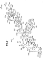
- An embodiment of the rope grab 100 is illustrated in the side perspective view of Figure 1 and the exploded view of the rope grab 100 in Figure 2 .
- the rope grab 100 includes a housing 200, a locking cam 300, a locking arm 400, a rotating side plate 500, and a fixed side plate 600.
- the locking cam 300, the locking arm 400 and the rotating side plate 500 are pivotally coupled to the housing 200 as further discussed below.
- the elements of the rope grab 100 are first described and then the construction and operation of the rope grab 100 are described.
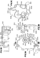
- the housing 200 of the rope grab 100 is further illustrated in Figures 3A through 3D .
- the housing 200 includes a body 202 that has a first side 303a and a second side 303b.
- the body 202 further has an upper end 202a and an opposed lower end 202b.
- Proximate the upper end 202a of the body 200 is positioned an upper end wall portion 201a that extends generally perpendicular from the first side 303a of the body 202.
- Proximate the lower end 202b of the body 202 is positioned a lower end wall portion 201b that extends generally perpendicular from the first side 303a of the body 202.
- the body 202 further has a first side edge 202c and an opposed second side edge 202d.
- Proximate the first side edge 202c of the housing 200 is a cable guide 231 that extends from the first side 303a of the body 202 in generally a C shape.
- the cable guide 231 forms a cable guide passage 230 (or elongated member passage) that extends from proximate the upper end 202a to the lower end 202b of the body 202.
- Proximate the lower end 202b of the body 202 of the housing 200 and proximate the first side 202c of the body 202 of the housing 200 is positioned a lower roller rivet passage 240 that passes through the body 202.
- a central post 204 extends generally perpendicular from the first side 303a of the body 202.
- the central post 204 is generally located at a mid-portion between the upper end 202a and the lower end 202b of the body 202 towards the second side edge 202d of the body 202 of the housing 200.
- the central post 204 includes a first central post portion 204a, a second central post portion 204b and third central post portion 204c.
- the first central post portion extends from the first side 303a of the body 202.
- the second central post portion 204b extends from the first central post portion 204a and has a diameter that is less than a diameter of the first central post portion 204a.
- the third central post portion 204c extends from the second central post portion 204b and has a diameter that is less than the diameter of the second central post portion 204b.
- a central post passage 206 passes through the central post 204.
- a cam spring holding channel 218 Surrounding the central post 204 is a cam spring holding channel 218 that is formed in the first side 303a of the body 202.
- the cam holding channel 218 includes a circular portion 218a and an extending leg portion 218b. In the embodiment shown, the leg portion 218b terminates in a spring retaining aperture 218c.
- a lever passage 212 passes through the body 202 of the housing 200 proximate the second side edge 202d and towards the lower end 202b of the body 202.
- the lever passage 212 is further positioned proximate the central post 204.
- the lever passage 212 includes a circular portion 212a and an extending portion 212b that extends from the circular portion 212a towards the lower end 202b of the body 202 of the housing 200.
- Proximate the lever passage 212 is a side wall portion 214 that extends generally perpendicular from the first side 303a of the body 202 of the housing 200.
- the side wall portion 214 is further generally positioned between the central post 204 and the lever passage 212.
- Proximate the side wall portion 214 is a mid-wall portion 216 that also generally extends perpendicular from the first side 303a of the body 202 of the housing 200.
- the mid wall portion 216 is also positioned proximate the lever passage 212.
- a raised portion 215 extends from the first side 303a of the body 202 of the housing 200.
- the raised portion 215 extends from the first side 303a of the body 202 around the lever passage 212.
- the height of the raised portion 215 is less than a height of the side wall portion 214 and a height of the mid wall portion 216.
- the housing 200 further includes a lower post 208 that is positioned proximate the lower end 202b of the body 202 of the housing 200.
- the lower post 208 extends from the first side 303a of the body 202 and includes a central lower post passage 210.
- the lower post 208 includes a first lower post portion 208a that extends from the first side 303a of the body 202 and a second lower post portion 208b that extends from the first lower post portion 208a.
- the second lower post portion 208b has a diameter that is less than a diameter of the first lower post portion 208a.
- the housing 200 also has an upper post 221 that extends from the first side 303a of the body 202.
- the upper post 221 is positioned proximate the upper end 202a of the body 202 and includes an upper post passage 220.
- a lever spring holding channel 211 is formed in the second side 303b of the body 202 of the housing 200 around a portion of the lever passage 212. Also illustrated in Figure 3C is a lever stop 233 that extends from the second side 303b of the body 202 of the housing 200 proximate the lever passage 212. The lever stop 233 is designed to stop rotation of lever 700 at a select orientation.
- the fixed side plate 600 is illustrated in Figures 4A and 4B .
- the fixed side plate includes an upper end 612 and an opposed lower end 614.
- the fixed side plate 600 further includes a first edge 616 and an opposed second edge 618.
- the fixed side plate 600 further includes a first side 602a and a second side 602b.
- a first connecting passage 606 passes through the fixed side plate 600 proximate the upper end 612 and the first edge 616.
- a second connection passage 608 passes through the fixed side plate 600 proximate the first edge 616 and the lower end 614.
- the fixed side plate 600 further includes a third connection passage 604 which is positioned generally at a mid-portion of the fixed side plate 600 and towards the second edge 618.
- a spring spacer bulge 602c extends from the first side 602a of the fixed side plate 600 creating a depression in the second side 602b of the fixed side plate 600 to receive an end of the spring spacer 112 as discussed further below.
- the third connection passage 604 is centrally located within the spring bulge 602c of the fixed side plate 600.
- the fixed side plate 600 also includes a lever passage 610 that is positioned proximate the second edge 618 of the fixed side plate 600 and between the third connection passage 604 and the lower end 614 of the fixed side plate 600.
- the second side edge 614 in this embodiment, has several edge extending portions that extend at select angles from each other so that the second side edge 614 conforms to the general shape of the second side edge 202d of the housing 200.
- the rotating side plate 500 includes a first edge 508 an opposed second edge 510.
- the rotating side plate 500 also includes an upper end 506 and an opposed lower end 504.
- the first edge 508 includes a plurality of edge portions 508a, 508b, 508c and 508d.
- the first portion 508a extends from the lower end 504 to the second portion 508b.
- the second portion 508b extends from the first portion 508a at a select angle.
- a third portion 508c extends from the second portion 508b at a select angle.
- the first, second and third portions 508a, 508b and 508c form a portion of the rotating side plate 500 that selectively blocks access to the cable guide passage 230 of the housing 200 as discussed further below.
- a fourth portion 508d extends from the third portion 508c to the upper end 506.
- the fourth portion 508d is generally curved forming generally a cutout section in the rotating side plate 500 that is designed to selectively receive the upper post 221 of the housing 200 when assembled.
- the second side edge 510 also has a plurality of edge portions 510a, 510b, 510c, 510d, 510e, 510f and 510g.
- a first portion 510a extends from the lower end 504.
- a second portion 510b extends from the first portion 510a.
- a third portion 510c extends from the second portion 510b.
- a fourth portion 510d extends from the third portion 510c and a fifth portion 510e extends from the fourth portion 510d.
- the third portion 510c, fourth portion 510d and the fifth portion 510e form a cutout section in the second edge 510 of the rotating side plate 500 that allows for movement of the rotating side plate 500 in relation to the spring spacer 112 when the rope grab 100 is assembled.
- the sixth portion 510f extends from the fifth portion 510e at a select angle.
- the seventh portion 510g extends between the sixth portion 510f and the upper end 506.
- the rotating side plate 500 further includes a first side surface 502a and a second side surface 502b.
- the rotating side plate 500 further includes a pivot connection passage 512 positioned proximate the lower end 504 and a roller connection passage 514 positioned proximate the upper end 506.
- Figures 6A through 6C illustrate an arm spring 110 of one embodiment.
- the arm spring 110 includes a central coiled portion 110a.
- the coiled portion 110a is positioned between a first end portion 110b and a second end portion 110c.
- the first end portion 110b extends inward in relation to the coiled portion 110a.
- the second end portion 110c extends in a direction away from the first end portion 110b and terminates in a bent holding end 111.
- the second end portion 110c of the arm spring 110 is shaped to engage an arm spring groove 409 of the locking arm 400 as discussed further below.
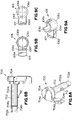
- Figures 7A through 7C illustrate a spring spacer 112 of one embodiment of the present invention.
- the spring spacer 112 includes generally a cylindrical body 112a having a first end 113 and an opposed second end 114.
- the body 112a of the spring spacer 112 further includes a central passage 115.
- a spring holding slot 112b is formed in the first end 113 of the spring spacer 112.
- the spring holding slot 112b extends across the first end 113 of the spring spacer 112 such that it extends into a portion of the central passage 115.
- the spring holding slot 112b is designed to receive the first end portion 110b of the arm spring 110 while the coiled portion 110a of the arm spring 110 is positioned around the cylindrical body 112a of the spring spacer 112.
- the spring spacer 112 further includes a bore 112c extending into the first end 113 of the cylindrical body 112a. The bore is used by a tool to put a required pre-wind on the arm spring 110 during assembly.
- FIGS 8A through 8B illustrate a first lever 700 of one embodiment of the present invention.
- the first lever 700 includes a stem 702 and an activation knob 704.
- the stem 702 includes a first stem portion 702a and a second stem portion 702b.
- the first stem portion 702a extends between the activation knob 704 and the second stem portion 702b.
- the second stem portion 702b has a diameter that is less than the diameter of the first stem portion 702a.
- An engaging tab 710 centrally extends from a surface of the first stem portion 702a.
- a pair of rotating locking tabs 708a and 708b opposably extend from a surface of the second stem portion 702b proximate the first stem portion 702a.
- the activation knob 704 includes a first disk portion 704a which is coupled to an end of the first stem portion 702a and a second extending portion 704b which extends away from the first disk portion 704a in a select direction.
- the second extending portion 704b provides leverage to rotate the stem 702.
- the activation knob 704 further has a third extending portion 704c that extends from the second extending portion 704b towards the stem portion 702.
- the third extending portion 704c is designed to selectively engage the lever stop 231 on the second side 303b of the housing 200 when assembled.
- Figures 9A through 9C illustrate a lock member 106 of one embodiment.
- the lock member 106 includes a cylindrical base member 106a and an extending portion 106d that extends away from the cylindrical base member 106a proximate an end of the cylindrical base member 106a.
- the lock member 106 has a first side 107 and an opposed second side 109.
- the cylindrical base member 106a includes a lock member passage 106c and a cutout section 106b that is positioned proximate the first side 107 of the lock member 106.
- Extending portion 106d includes a lock spring holding channel 106e that is formed in the second side 109 of the locking member 106.
- the lock spring holding channel 106e extends across the width of the extending portion 106d.
- the extending portion 106d further includes a lock spring holding slot 106f in a side of the extending portion 106d that extends a height of the extending portion 106d.
- the lock spring holding slot 106f extends into the lock spring holding channel 106e.
- the locking arm 400 includes a locking arm main portion 402 and a locking arm energy absorber portion 404.
- the locking arm main portion 402 includes a main locking arm passage 412.
- a locking arm extending portion 408 extends from the locking arm main portion 402 in a direction that is opposite a direction that the locking arm energy absorber portion 404 extends from the locking arm main portion 402.
- An arm spring groove 409 is formed in an edge proximate a junction between the locking arm main portion 402 and the locking arm energy absorber 404.
- the locking arm energy absorber portion 404 includes an energy absorber connector passage 406 proximate a termination end of the locking arm energy absorber portion 404.
- the energy absorber connection passage 406 is used to connect a safety harness (not shown) donned by a user to the rope grab 100 as further discussed below.
- a safety harness (not shown) donned by a user to the rope grab 100 as further discussed below.
- a frontal D-ring of a safety harness would be coupled to the swivel connector 122 attached to the energy absorber portion 404 of the locking arm 400 via carabiner (not shown).
- the locking arm energy absorber portion 404 is designed to straighten out therein absorbing energy to prevent injuries to the user.
- the locking cam 300 includes a cam body 302.
- the cam body 302 of the locking cam 300 includes a connection portion 302a and an engagement portion 302b.
- the cam body 302 further includes a first side 301a and a second side 301b.
- the connection portion 302a of the cam body 302 includes a cam passage 304.
- Proximate the cam passage 304 in the connection portion 302a of the locking cam 300 is a cam spring holding portion 306 which includes a cam spring passage 306b which extends through the locking cam 300 and a cam spring slot 306a which is formed in the first side 301a of the cam body 302.
- the cam spring slot 306a leads to the cam spring passage 306b.
- a portion of a cam spring 132 (a cam biasing member) illustrated in Figure 2 is received in the cam whole spring holding portion 306 as further described below.
- the first side 301a of the cam body 302 further includes a recessed portion 312 that is positioned proximate the cam spring holding portion 306 and extending to an edge of the cam body 302.
- the recessed portion 312 provides room for movement of the holding end 111 of the second end portion 110c of the arm spring 110 engaging the locking arm 400 when the rope grab is assembled.
- the engaging portion 302b of the locking cam 300 extends from the connection portion 302a.
- the width of the engaging portion 302b is greater than the width of the connection portion 302a.
- the width of the engaging portion 302b extends wider than the width of the connection portion 302a in the direction of the first side 301a of the cam body 302.
- the engaging portion 302b of the locking cam 300 further terminates in a radial edge 302c.
- the radial edge 302c extends generally radially about cam passage 304 with a varied radial configuration as described below.
- the radial edge 302c has generally a concave surface with a plurality of extending gripping tabs 310 that are designed to frictionally engage an elongated member.
- the engaging portion 302b of the locking cam 300 further includes a first side edge 320 and a second side edge 321 that respectively extend from the connection portion 302a to the radial edge 302c.
- the second side edge 321 extends generally in a straight line from the connection portion 302a to the radial edge 302c.
- the first side edge 320 has a plurality of first side edge portions 320a, 320b and 320c.
- the first side edge portion 320a extends from the connection portion 302a in generally a perpendicular fashion.
- the second side edge portion 320b extends from the first side edge portion 320a in generally a curved configuration.
- the third side edge portions 320c extends from the second side edge portion 320b in generally a straight line to the radial edge 302c.
- the locking cam 300 further includes a hub portion 303 that extends around the cam passage 304 of the connection portion 302a of the cam body 302. The hub 303 extends out from the second side 301b of the cam body 302.
- the engaging portion 302b of the locking cam 300 further includes a third edge 330 that defines the engaging portion 302b from the connection portion 302a.
- the third edge 330 includes a locking arm engaging surface 332.
- the extending portion 408 of the locking arm 400 engages the locking arm engaging surface 332 of the locking cam 300 during a fall event as the locking arm 400 as further discussed below.
- a cam spring 132 having a coiled section 132a and a first end 132b is received in the cam spring holding channel 218 of the body 202 of the housing 200.
- the coiled section 132a of the cam spring 132 is received in the circular portion 218a of the cam spring holding channel 218 and the first end 132b of the cam spring 132 is received in the leg portion 218b of the cam spring holding channel 218.
- This configuration retains a first end of the cam spring 132 in a static configuration in relation to the housing 200.
- a first bearing 128 is positioned within the cam passage 304 of the locking cam 300.
- the cam passage 304 is then positioned around the first post portion 204a of the central post 204 of the housing 200.
- a second end 132c of the cam spring 132 is passed through the cam spring passage 306b and received in the cam spring slot 306a of the cam spring holding portion 306 of the locking cam 300.
- This arrangement of the cam spring 132 provides a relatively light biasing force on the locking cam 300 to rotate the locking cam 300 towards an elongated member in the elongated member passage 230 of the housing 200.
- This relatively light biasing force is countered by gravity in normal climbing operations which keeps the cam lock 300 from locking onto the elongated member. Hence during normal operations, the rope grab 100 moves relatively freely up and down the elongated member.
- a second bearing 126 is positioned in the main locking arm passage 412 of the locking arm 400.
- the main locking passage 412 of the locking arm is then positioned around the second post portion 204b of the central post 204 of the housing 200.
- the spring spacer 112 is then positioned around the third post portion 204c of the central post 204.
- the coiled portion 110a of the arm spring 110 is positioned around the spring spacer 112 while the first end portion 110b of the arm spring 110 is received in the spring holding slot 112b of the spring spacer 112.
- the first end portion 110b of the arm spring 110 is further received in the cut out section 203 of the third post portion 204c of the post 204 of the housing 200.
- This arrangement holds the first end portion 110b of the arm spring 110 in a static position in relation to the housing 200.
- the second end portion 110c of the arm spring 110 is received in the arm spring groove 409 of the locking arm 400 to assert a biasing force on the locking arm 400 in a locked position.
- a fastener such as rivet 142 passing through the central post passage 206 of the central post 204 of the housing 200 and the third connector passage 604 of the fixed side plate 600 couples the housing 200 to the fixed side plate 600.
- a lever spring 138 is positioned over the stem 702 of the first lever 700.
- the stem 702 of the first lever 700 is in turn passed through the lever passage 212 of the housing 200.
- a first end portion 138a of the lever spring 138 is received in a spring holding bore 705 in the first lever 700.
- a second end portion 138b of the lever spring 138 is positioned in a gap in the second side edge 214 of the housing 200 so that a biasing force is exerted on the stem 702 of the first lever 700 in a desired direction.
- the extending portion 212b of the lever passage 212 allows the engaging tab 710 (shown in Figure 8A ) extending from the stem 702 of the first lever 700 to pass through the lever passage 212.
- the lock spring 108 is positioned around the stem 702.
- a first end portion 108a of the lock spring 108 engages a portion of the second side wall 214 of the housing 200 to hold the first end portion 108a of the lock spring 108 in a static location in relation to the housing 200.
- the stem 702 of the first lever 700 is then passed through the lock member passage 106c of the lock member 106.
- the engaging tab 710 of the stem 702 of the first lever 700 is received in the cut out section 106b of the lock member 106 to lock the rotation of the stem 702 with the rotation of the lock member 106.
- a second end portion 108b of the lock spring 108 is received in the lock spring holding channel 106e of the extending portion 106d of the lock member 106 to exert a biasing force on the lock member 106 in a desired direction.
- the stem 702 is then further passed through the lever passage 610 in the fixed side plate 600.
- a washer 104 and a second lever 102 are then coupled on the second stem portion 702b of the stem 702.
- the second lever 102 includes a stem connection passage 102c with opposed grooves 102a and 102b.
- the opposed grooves 102a and 102b respectfully receive the rotation locking tabs 708a and 708b of the stem 702 of the first lever 700 to lock rotation of the second lever 102 to the rotation of the stem 702.
- a first fastener 140 (first rivet) passing through the upper post passage 220 of the upper post 221 of the housing 200 and through the first connection passage 606 in the fixed side plate 600 and a second fastener 144 (second rivet) passing through the lower post passage 210 of the lower post 208 of the housing 200 and through the second connection passage 608 in the fixed side plate 600 further couples the housing 200 to the fixed side plate 600.
- the second fastener 144 further passes through the pivot connection passage 512 of the rotating side plate 500 to provide a pivot connection for the rotating side plate 500.
- the rope grab 100 further includes an upper roller 114 and a lower roller 134 to guide the elongated member through the cable guide channel 230 of the housing 200.
- the upper roller 114 is rotationally coupled to the rotating side plate 500 via upper roller rivet 116.
- the lower roller 134 is rotationally coupled to the housing 200 adjacent the cable guide 231 of the housing 200 via lower rivet 136.
- a lifeline swivel connector 122 is coupled to the energy absorbing portion 404 of the locking arm 400 via swivel pivot connector 118.
- the swivel lifeline connector 122 includes a base 121c with a connection passage 121 and a pair of spaced arms 122a and 122b with aligned passages 123a and 123b.
- a pair of spaced arms 118a and 118b of a swivel pivot connection 118 is passed through the connection passage 121 of the swivel lifeline connector 122.
- a head portion 118c of the swivel pivot connection 118 has a diameter larger than the diameter of the connection passage 121 of the swivel lifeline connector 122.
- the pair of spaced arms 118a and 118b have aligned swivel pivot connection passages 117.
- a rivet 120 passes through the aligned swivel pivot connection passages 117 and the connection passage 406 of the locking arm 400 to couple the swivel lifeline connector 122 to the locking arm 400.
- a rivet 124 passed through the aligned passages 123a and 123b of the swivel lifeline connector 122 is used to couple a lifeline to the rope grab 100. As discussed above, the lifeline would be coupled to a safety harness (not shown) donned by a user.
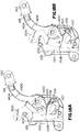
- Figure 10A illustrates the rotating side plate 500 in a retaining configuration in which a portion of the rotating side plate 500 proximate the first edge 508 of the rotating side plate 500 covers at least a portion of the side opening 150 to the cable guide passage 230.
- an elongated member (not shown in Figure 10A ) is retained in the cable guide passage 230 of the cable guide 231 of the housing 200.
- the retaining configuration is achieved when the extending portion 106d of the lock member 106 engages the second edge portion 510b of the second edge 510 of the rotating side plate 500 which retains the rotating side plate 500 in a static location in relation to the cable guide 231.
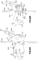
- FIG. 10B illustrates the rotating side plate 500 in an open configuration.
- a portion of the rotating side plate 500 proximate the first edge 508 of the rotating side plate 500 is moved far enough away from the cable guide 231 to allow passage of an elongated member into and out of the cable guide passage 230 through the side opening 150 to the cable guide passage 230.
- at least one of the first and second levers 700 and 102 is rotated, which rotates the extending portion 106d of the lock member 106 away from the second edge portion 510b of the second edge 510 of the rotating side plate 500.
- the rotating side plate 500 must be rotated by hand after at least one of the levers 700 or 102 is rotated. This is done by pulling back on the rotating side plate 500 proximate the upper roller 114.
- the rope grab 100 is designed so that a user can both rotate one of the levers 700 or 102 and pull back on the rotating side plate 500 to put the rotating side plate in the open configuration with a single hand. Once in the open position, an elongated member can be slid into or out of the cable passage 230.
- the rotating side plate 500 can be released to rotate the rotating side plate 500 to the retaining position and the lever 700 or 102 can be released to engage the lock member 106 to the rotating side plate 500.
- the partial cross-sectional side views of the rope grab 100 of Figure 12A and 12B illustrate the rope grab 100 engaging two different elongated members 702 and 714 respectfully.
- the elongated members 702 and 714 may be a rope, a cable or any type of elongated member that can be used as a safety support member.
- One of the features of embodiments of the present invention is that the elongated members 702 and 714 may have different diameters, as illustrated in Figures 12A and 12B , but will have the same contact angle 720 (Alpha 1 and Alpha 2). That is, the curvature of the radial edge 302c of the locking cam 300 is not constant in relation to the central post passage 206.
- the curvature varies so that the same contact angle 720 between the radial edge 302c of the locking cam 300 and the cable guide 231 of the housing is achieved for a range of diameters of the elongated members.
- the contact angle 720 is an angle that provides sufficient holding friction of the rope grab 100 between the radial edge 302c of the locking cam 300 and the cable guide 231 during a fall event. This is further discussed below.
- FIGS. 12A and 12B illustrate the rope grab 100 in use after the elongated member 702 or 714 has been positioned within the cable guide passage 230 of the housing 200.
- the elongated members 702 or 714 are guided through the cable guide passage 230 formed by the cable guide 231 with the upper roller 114 and the lower roller 134.
- the locking cam rotates to the open position under the influence of gravity, so a minimal (if any) frictional force is applied to the elongated member via the rope grab 100.
- the rope grab 100 in a normal non-fall event use, is relatively free to move up and down on the elongated member with the movement of the user who would be coupled to the locking arm via carabiner or other connecting means and safety harness (not shown).
- Figures 12A and 12B illustrate that in this embodiment during normal use, a portion of the mid-side wall portion 216 of the body 202 of the housing 200 rests in the locking arm engaging groove 410 of the locking arm 400.
- a user's frontal attachment to the user's harness that is coupled to the swivel connector 122 (which is in turn coupled to the locking arm 400) will pull the locking arm 400 down, therein rotating locking arm 400 about the central post 204.
- This movement causes the extending portion 408 of the locking arm 400 to engage the locking arm engaging surface 332 of the locking cam 300 therein pivoting the locking cam 300 also about the central post 204 of the housing 200.
- This movement of the locking cam 300 forces the radial edge 302c of the locking cam 300 to forcefully pinch a portion of the elongated member 702 or 714 between the radial edge 302c of the locking cam 300 and the cable guide 231 of the housing 200 therein locking movement of the rope grab 100 in relation to the elongated member 702 or 714. If the force is great enough during the fall event, the energy absorber portion 404 of the locking arm 400 will straighten out to absorb energy and prevent injury to the user. The rope grab 100 will remain locked onto the elongated member 702 or 714 until the downward force of the fallen user is removed.
- the gravitation forces on the cam lock 300 are overcome by the light biasing force of the cam spring 132 as well as by inertial forces, to also cause the cam lock 300 to lock onto the elongated members 702 or 714.
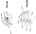
- the profile of the radial edge 302c of the locking cam 300 for a given contact angle 720 is determined by dividing the locking cam 300 into multiple thin slices separated by planes 350 that are perpendicular to the profile of the radial edge 302c and pass through a rotational axis 360 of the locking cam 300.
- the profile of the radial edge 302c is generated by creating edges 352 that maintain an angle 354 (Beta) between the profile of the radial edge 302c of the locking cam 300 and the planes 350 separating the thin slices of the locking cam 300.
- Angle Beta 354 is equal to 90° - contact angle 702 (Alpha 1 or Alpha 2).
- Embodiments of the present invention further includes a bypass bracket 800 that is designed to be coupled to a support structure and to hold an elongated member that the rope grab 100 is engaging in a generally static position.
- a bypass bracket 800 is illustrated in Figures 14A and 14B .
- the bypass bracket 800 includes a base bracket 802.
- the base bracket 802 includes a first section 802a and a second section 802b.
- the second section 802b generally extends from the first section 802a in a perpendicular fashion.
- the first section 802a includes two spaced connection apertures 806a and 806b.
- the second section 802b of the base bracket 802 includes a first connection aperture 804a and a second connection aperture 804b.
- the bypass bracket 800 further includes a clamp member 810.
- This embodiment of the clamp member 810 is made from a plate that has a first side edge 810a and an opposably positioned second side edge 810b.
- the client member 810 further includes a top edge 810c and an opposably positioned bottom edge 810d.
- the clamp member 810 further includes a centrally positioned upper connection aperture 812 that is positioned proximate the upper edge 810c of the clamp member 810.
- the clamp member 810 also includes a slot 814 that extends in the first side edge 810a of the clamp member 810 proximate the lower edge 810d of the clamp member 810.
- a support structure such as, but not limited to, a rung of a ladder is positioned between the first section 802a of the base bracket 802 and the clamp member 810.
- a fastener 816a then passes through a connection aperture 806a in the base bracket 802 and the upper connection aperture 812 of the clamp plate member 810.
- a nut 818a is then threadably engaged to the fastener 816a to couple an upper portion of the clamp member 810 to the base bracket 802.
- a fastener 816b is passed through a connection aperture 806b of the base bracket 802 and within slot 814 of clamp member 810.
- Nut 818b is then threadably engaged to the fastener 816b to couple a lower portion of the clamp member 810 to the base bracket 802.
- the bypass bracket 800 further includes a sleeve clip 820.
- the sleeve clip 820 includes a first portion 820a that has first and second connection apertures 823 (only one connection aperture 823 is shown in Figure 14B ).
- the connection apertures 823 are aligned with the first and second connection apertures 804a and 804b of the base bracket 802. Rivets 824a and 824b passing through the respective connection apertures 823, 804a and 804b couple the sleeve clip 820 to the base bracket 802.
- the sleeve clip 820 further includes a second portion 820b that extends from the first portion 820a in generally a perpendicular fashion.
- the second portion 820b includes holding ears 822a and 822b.
- the ears 822a and 822b are spaced by a central spaced portion 825.
- the first holding ear 822a has a generally C-shaped configuration with its open side facing a first direction.
- the second holding ear 822b is also in generally a C-shaped configuration with its open side facing a second direction that is generally opposite the first direction.
- the ears 822a and 822b form a receiving sleeve channel 821 that is formed from a first channel 821a formed by the first holding ear 822a and a second channel 821b formed by the second holding ear 822b.
- a sleeve 830 is used in conjunction with the bypass bracket 800.
- the sleeve 830 has a tubular configuration with a central passage 832.
- An elongated member (such as elongated member 920 shown in Figure 15A ) is received within the central passage.
- the sleeve 830 further includes a first recess section 831a and a second recessed section 831b.
- the first and second recess sections 831a and 831b are recessed into an outer surface of the sleeve 830 in an opposable fashion.
- the first and second recessed sections 831a and 831b are spaced from each other by a mid-portion 830a of the sleeve 830.
- the first recess portion 831a is configured to receive the first holding ear 822a of the sleeve clip 820 and the second recessed portion 831b is configured to receive the second holding ear 822b of the sleeve clip 820.
- the sleeve 830 (having the elongated member 920 passing through its central passage 832) is tilted in relation to the receiving sleeve channel 821 (approximately 90 degrees) and positioned such that the mid-portion of the sleeve 830 is received in the space 825 between the holding ears 822a and 822b of the sleeve clip 820.
- the sleeve 830 is tilted to align with the receiving sleeve channel 821 of the sleeve clip 820, therein allowing the first ear 822a of the sleeve clip 820 to be received in the first recess 831a of the sleeve and the second holding ear 822b to be received in the second recess 831b of the sleeve 830.
- This locks the sleeve 830 within the sleeve clip 820 of the bypass bracket 800.
- This design allows the bypass brackets 800 to be attached to support structures prior to the connection to the elongated member 920.
- the bypass bracket 800 is designed to hold the elongated member 920 stationary while not interfering with the function of the rope grab 100. Referring to Figures 15A through 15C an illustration of this is provided.
- the bypass bracket 800 in this embodiment includes a clamp member 811 that has an edge with teeth 811a that are designed to grip the support structure 900.
- Figures 15A through 15C illustrate the rope grab 100 as it is passing across the bypass bracket 800.
- the side view of Figure 15B illustrates the rope grab 100 without the fixed side plate 600 for illustration purposes.
- the sleeve 830 that holds the elongated member 920 is received in the cable guide passage 230 of the rope grab 100.
- the locking cam 300 will allow it to pass unless a fall event occurs.
- a system may include a plurality of bypass brackets 800 to position a support structure 920 in a desired location.
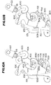
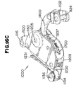
- FIG. 16A illustrates a first side perspective view of the rope grab 1000
- Figure 16B illustrates a second side perspective view of the rope grab 1000
- Figure 16C illustrates a rear perspective view of the rope grab 1000
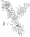
- an exploded first side view of the rope grab 1000 is illustrated in Figure 17 .
- rope grab 1000 includes a housing 1200, a locking cam 1300, a locking arm 1400, a rotating side plate 1500, and a fixed side plate 1600.
- the locking cam 1300, the locking arm 1400 and the rotating side plate 1500 are pivotally coupled to the housing 1200.
- the housing 1200 of rope grab 1000 includes rear slot 1207 best shown in Figures 16C and Figure 17 .
- a lever 1700 extends through the rear slot 1207 in this embodiment.
- Proximate a front first side edge of the housing 1200 is a cable guide 1231 that extends from a first side edge of the housing 1200 in generally a C shape.
- the cable guide 1231 forms a cable guide passage 1230 (or elongated member passage) that extends from proximate an upper end to a lower end of the housing 1200.
- a central post 1204 extends generally perpendicular from the first side of the housing 1200. The central post 1204 is generally located at a mid-portion between an upper end and a lower end of the housing 1200 towards a second side edge of the housing 1200 similar to central post 204 of rope grab 100 discussed above.
- the cam passage 1340 of the locking cam 1300 as well as passages in the cam spring 1132, the first bearing 1128, washer 1119, second bearing 1117, the spring spacer 1112, the arm spring 1110 are all received around the central post 1204 of the housing 1200.
- the central post 1204 includes an end portion 1205 that is received in a connection passage 1604 in the fixed side plate 1600 to couple the housing 1200 to the fixed side plate 1600.
- the housing 1200 includes a cam spring holding channel 1218 that surrounds the central post 1204.
- the cam holding channel 1218 includes a circular portion and an extending leg portion to hold a first side of the cam spring 1132. A second side of the spring engages the locking cam 1300.
- This arrangement of the cam spring 1132 provides a relatively light biasing force on the locking cam 1300 to rotate the locking cam 1300 towards an elongated member (cable or rope) in the elongated member passage 1230 of the housing 1200.
- This relatively light biasing force is countered by gravity in normal climbing operations which keeps the cam lock 1300 from locking onto the elongated member.
- the rope grab 1000 moves relatively freely up and down the elongated member.
- gravitational forces do not counteract the light biasing force of the cam spring 1132 and the locking cam 1300 will lock onto the elongated member.
- Inertial loads on the locking cam 1300 during a fall also work in tandem with the light biasing force of the cam spring 1132 to rotate the locking cam 1300 onto the elongated member.
- the locking arm 1400 does not include an energy absorbing portion like locking arm 400 described above.
- Locking arm 1400 does include a locking arm extending portion 1408 and a connecting arm 1404.
- the locking arm extending portion 1408 is designed to engage a portion of the locking cam 1300 during a fall event to engage a radial edge 1302 into the elongated member as described above regarding locking arm extending portion 408 and the locking cam 300.
- the connecting arm 1404 includes a connecting aperture 1406 in which a connector 1350 is attached.
- a lifeline swivel connector 1122 is coupled to the connecting aperture 1406 of the locking arm 1400 via swivel pivot connector 1118.
- the swivel lifeline connector 1122 includes a base with a connection passage 1121 and a pair of spaced arms 1122a and 1122b with aligned passages 1123a and 1123b.
- a pair of spaced arms 1118a and 1118b of a swivel pivot connector 1118 is passed through the connection passage 1121 of the swivel lifeline connector 1122.
- a head portion 1118c of the swivel pivot connector 1118 has a diameter larger than the diameter of the connection passage 1121 of the swivel lifeline connector 1122.
- the pair of spaced arms 1118a and 1118b have aligned swivel pivot connection passages 1115a and 1115b.
- a rivet 1120 passes through the aligned swivel pivot connection passages 1115a and 1115b and the connection passage 1406 of the locking arm 1400 to couple the swivel lifeline connector 1122 to the locking arm 1400.
- a rivet 1124 passed through the aligned passages 1123a and 1123b of the swivel lifeline connector 1122 is used to couple a lifeline to the rope grab 1000.
- the carabiner 1350 is selectively coupled to the rivet 1124.
- the carabiner 1350 would be coupled to a safety harness (not shown) donned by a user.
- the second bearing 1117 is positioned in a main locking arm passage 1412 of the locking arm 1400.
- the main locking passage 1412 of the locking arm is then positioned around the central post 1204 of the housing 1200 as described above.
- the spring spacer 1112 is also positioned around another portion of the central post 1204.
- the coiled portion of the arm spring 1110 is positioned around the spring spacer 1112 while a first end portion 1110a of the arm spring 1110 is received in a spring holding slot 1112b of the spring spacer 1112.
- the first end portion 1110a of the arm spring 1110 is further received in a cut out section 1203 of the center post 1204 of the housing 1200. This arrangement holds the first end portion 1110a of the arm spring 1110 in a static position in relation to the housing 1200.
- a second end portion 1110b of the arm spring 1110 is received in the arm spring groove 1409 of the locking arm 1400 to assert a biasing force on the locking arm 1400 in a locked position.
- the rotating side plate 1500 includes an upper portion with a roller passage 1514 and lower portion with a pivot connection passage 1512.
- the upper roller 1114 is rotationally coupled to side plate 1500 via pin 1116.
- the pivot connection passage 1512 receives a second post 1208 of the housing 1200.
- the rotating side plate 1500 further includes a first edge 1508 and an opposed second edge 1510.
- the rotating side plate 1500 further includes a first cut out section 1533 that extends in from the second edge 1510 near the lower portion and a centrally located second cut out section 1531 to reduce weight of the rope grab 1000.
- Also included along the second edge 1510 of the rotating side plate 1500 is a lock surface portion 1511 and an extending tab 1502.
- the first cut out section 1533 is positioned between the lock surface portion 1511 and the extending tab 1502.
- a side plate spring 1130 is also received on a second post 1208 of the housing 1200.
- a biasing force from the side plate spring 1130 engaging the extending tab 1502 biases the rotating side plate 1500 to the retaining configuration.
- the rotating side plate 1500 must be rotated by hand after lever 1700 (discussed below) is rotated. This is done by pulling back on the rotating side plate 1500 proximate the upper roller 1114. Once in the open position, an elongated member can be slid into or out of the cable passage 1230.
- the rotating side plate 1500 can be released to rotate the rotating side plate 1500 to the retaining position and the lever 1700 can be released to engage the lock member 1106 (discussed below) to the rotating side plate 1500.
- the lever 1700 and an associated lever biasing member 1109 are mounted on a third post 1211 extending from the housing 1200.
- the lever 1700 is rotationally mounted on the third post 1211.
- the lever biasing member 1109 biases the lever 1700 into a locked position with one end engaging the lever 1700 and another end engaging the housing 1200.
- the lock member 1106 and a lock member biasing member 1108 are also mounted on the third post 1211.
- the lock member biasing member 1108 biases the lock member 1106 in a lock position so that a lock portion 1107 of the lock member engages the lock surface portion 1511 of the rotating side plate 1500.
- a raised tab 1701 of lever 1700 is received in a slot 1105 of the lock member 1106 to rotate the lock portion 1107 of the lock member 1106 away from the lock surface portion 1511 of the rotating side plate when the lever 1700 is rotated.
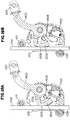
- Figure 18A illustrates the rotating side plate 1500 in a retaining configuration in which a portion of the rotating side plate 1500 proximate the first edge 1508 of the rotating side plate 1500 covers at least a portion of the side opening 1150 to the cable guide passage 1230.
- an elongated member (not shown in Figure 18A ) is retained in the cable guide passage 1230 of the cable guide 1231 of the housing 1200.
- the retaining configuration is achieved when the extending portion 1107 of the lock member 1106 engages the lock surface portion 1511 of the second edge 1510 of the rotating side plate 1500 which retains the rotating side plate 1500 in a static location in relation to the cable guide 1231.
- the lock member biasing member 1108 biases the lock member 1106 in this configuration.
- Figure 18B illustrates the rotating side plate 1500 in an open configuration. In this configuration, a portion of the rotating side plate 1500 proximate the first edge 1508 of the rotating side plate 1500 is moved far enough away from the cable guide 1231 to allow passage of an elongated member into and out of the cable guide passage 1230 through the side opening 1150 to the cable guide passage 1230.
- lever 1700 is rotated, which rotates the extending portion 1107 of the lock member 1106 away from the lock surface portion 1511 of the second edge 1510 of the rotating side plate 1500.
- the biasing force from the side plate spring 1130 engaging the extending tab 1511 biases the rotating side plate 1500 to the retaining configuration.
- the rotating side plate 1500 must be rotated by hand after lever 1700 is rotated. This is done by pulling back on the rotating side plate 1500 proximate the upper roller 1114.
- the rope grab 1000 is designed so that a user can both rotate the lever 1700 and pull back on the rotating side plate 1500 to put the rotating side plate in the open configuration with a single hand.
- an elongated member can be slid into or out of the cable passage 1230. Once the elongated member is positioned in or taken out of the cable passage 1230, the rotating side plate 1500 can be released to rotate the rotating side plate 1500 to the retaining position and the lever 1700 can be released to engage the lock member 1106 to the rotating side plate 1500.
- FIGS 19A and 19B illustrate the rope grab 1000 in use after the elongated member 1702 or 1714 has been positioned within the cable guide passage 1230 of the housing 1200.
- the elongated members 1702 or 1714 are guided through the cable guide passage 1230 formed by the cable guide 1231 with the upper roller 1114 and the lower roller 1134.
- the locking cam 1300 rotates to the open position under the influence of gravity, so a minimal (if any) frictional force is applied to the elongated member via the rope grab 1000.
- the rope grab 1000 in a normal non-fall event use, is relatively free to move up and down on the elongated member with the movement of the user who would be coupled to the locking arm 1400 via carabiner or other connecting means and safety harness (not shown).
- Figures 19A and 19B illustrate that the rope grab 1000 can be used on different sized elongated members 1702 and 1714.
- the portion of the radial engaging edge 1302 of the locking cam 1300 that engages the elongated member depends on the diameter of the elongated member 1702 and 1714.
- This movement of the locking cam 1300 forces the radial engaging edge 1302 of the locking cam 1300 to forcefully pinch a portion of the elongated member 1702 or 1714 between the radial edge 1302 of the locking cam 1300 and the cable guide 1231 of the housing 1200 therein locking movement of the rope grab 1000 in relation to the elongated member 1702 or 1714.
- the rope grab 1000 will remain locked onto the elongated member 1702 or 1714 until the downward force of the fallen user is removed.
- the gravitation forces on the cam lock 1300 are overcome by the light biasing force of the cam spring 1132 as well as by inertial forces, to also cause the cam lock 1300 to lock onto the elongated members 1702 or 1714.
- FIG. 20A illustrates a first side perspective view of the rope grab 2000
- Figure 20B illustrated a second side perspective view of the rope grab 2000
- an exploded first side view of the rope grab 2000 is illustrated in Figure 21 .
- rope grab 2000 includes a housing 2200, a locking cam 2300, a locking arm 2400, a rotating side plate 2500, and a fixed side plate 2600.
- the locking cam 2300, the locking arm 2400 and the rotating side plate 2500 are pivotally coupled to the housing 2200.
- the housing 2200 of rope grab 2000 includes a cable guide 2231 that extends from the first side edge of the housing 2200 in generally a C shape.
- the cable guide 2231 forms a cable guide passage 2230 (or elongated member passage) that extends from proximate an upper end to a lower end of the housing 2200.
- Proximate the lower end of the housing 2200 and cable guide 2231 is positioned lower roller rivet passages 2340 that passes through the housing 2200.
- a rivet 2142 passing through the lower roller rivet passages 2340 rotationally couples a lower roller 2134 to the housing 2200.
- a central post 2204 extends generally perpendicular from the first side of the housing 2200.
- the central post 2204 is generally located at a mid-portion between an upper end and a lower end of the housing 2200 towards a second side edge of the housing 2200 similar to central post 204 of cable grab 100 discussed above. Also similar to cable grab 100, the cam passage 2304 of the locking cam 2300 as well as passages in the cam spring 2132, the first bearing 2128, second bearing 2117, the spring spacer 2112, the arm spring 2110 are all received around the central post 2204 of the housing 2200.
- the central post 2204 includes an end portion 2205 that is received in a connection passage 2604 in the fixed side plate 2600 to couple the housing 2200 to the fixed side plate 2600.
- the housing 2200 includes a cam spring holding channel 2218 that surrounds the central post 2204.
- the cam holding channel 2218 includes a circular portion and an extending leg portion to hold a first side of the cam spring 2132. A second side of the spring engages the locking cam 2300.
- This arrangement of the cam spring 2132 provides a relatively light biasing force on the locking cam 2300 to rotate the locking cam 2300 towards an elongated member (cable) in the elongated member passage 2230 of the housing 2200.
- This relatively light biasing force is countered by gravity in normal climbing operations which keeps the cam lock 2300 from locking onto the elongated member.
- the rope grab 2000 moves relatively freely up and down the elongated member.
- Locking arm 2400 does not include an energy absorbing portion like locking arm 400 described above.
- Locking arm 2400 does include a locking arm extending portion 2408 and a connecting arm 2404.
- the locking arm extending portion 2408 is designed to engage a portion of the locking cam 2300 during a fall event to engage a radial edge 2302 into the elongated member as described above regarding the locking arm extending portion 408 and the locking cam 300.
- the connecting arm 2404 includes a connecting aperture 2406 in which a connector 2350 is attached.
- a lifeline swivel connector 2122 is coupled to the connecting aperture 2406 of the locking arm 2400 via swivel pivot connector 2118.
- the swivel lifeline connector 2122 includes a base with a connection passage 2121 and a pair of spaced arms 2122a and 2122b with aligned passages 2123a and 2123b.
- a pair of spaced arms 2118a and 2118b of a swivel pivot connection 2118 is passed through the connection passage 2121 of the swivel lifeline connector 2122.
- a head portion 2118c of the swivel pivot connection 2118 has a diameter larger than the diameter of the connection passage 2121 of the swivel lifeline connector 2122.
- the pair of spaced arms 2118a and 2118b have aligned swivel pivot connection passages 2115a and 2115b.
- a rivet 2120 passes through the aligned swivel pivot connection passages 2115a and 2115b and the connection passage 2406 of the locking arm 2400 to couple the swivel lifeline connector 2122 to the locking arm 2400.
- a rivet 2124 passed through the aligned passages 2123a and 2123b of the swivel lifeline connector 2122 is used to couple a lifeline to the rope grab 2000.
- the carabiner 2350 is selectively coupled to the rivet 2124.
- the carabiner 2350 would be coupled to a safety harness (not shown) donned by a user.
- the second bearing 2117 is positioned in a main locking arm passage 2412 of the locking arm 2400.
- the main locking passage 2412 of the locking arm is then positioned around the central post 2204 of the housing 2200 as described above.
- the spring spacer 2112 is also positioned around another portion of the central post 2204.
- the coiled portion of the arm spring 2110 is positioned around the spring spacer 2112 while a first end portion 2110a of the arm spring 2110 is received in a spring holding slot 2112b of the spring spacer 2112.
- the first end portion 2110a of the arm spring 2110 is further received in a cut out section 2203 of the center post 2204 of the housing 2200. This arrangement holds the first end portion 2110a of the arm spring 2110 in a static position in relation to the housing 2200.
- a second end portion 2110b of the arm spring 2110 is received in the arm spring groove 2409 of the locking arm 2400 to assert a biasing force on the locking arm 2400 in a locked position.
- the rotating slide plate 2500 includes an upper portion with a roller passage 2514 and lower portion with a pivot connection passage 2512.
- the upper roller 2114 is rotational coupled to slide plate 2500 via pin 2116.
- the pivot connection passage 2512 receives at second post 2208 of the housing 2200.
- the rotating slide plate 2500 further includes a first edge 2508 and an opposed second edge 2510.
- the rotating side plate 2500 further includes a first cut out section 2533 that extends in from the second edge 2510 near the lower portion and a centrally located second cut out section 2531 to reduce weight of the rope grab 2000. Also included in along the second edge 2510 of the rotating side plate 2500 is a lock surface portion 2511 and an extending tab 2502.
- the first cut out section 2533 is positioned between the lock surface portion 2511 and the extending tab 2502.
- a side plate spring 2108 is also received on a second post 1208 of the housing 2200.
- a biasing force from the side plate spring 2108 engaging the extending tab 2502 biases the rotating side plate 2500 to the retaining configuration.
- the rotating side plate 2500 must be rotated by hand after lever 2700 or 2102 (discussed below) is rotated. This is done by pulling back on the rotating side plate 2500 proximate the upper roller 2114. Once in the open position, an elongated member can be slid into or out of the cable passage 2230.
- the rotating side plate 2500 can be released to rotate the rotating side plate 2500 to the retaining position and the lever 2700 or 2102 can be released to engage the lock member 2106 (discussed below) to the rotating side plate 2500.
- the first lever 2700 includes a lever post 2701 that extends though a first lever passage 2207 in the housing 2200 and a second lever passage 2607 in the fixed side plate 2600.
- the second lever 2102 and a washer 2104 are mounted to an end of the lever post 2701.
- this embodiment has two levers 2700 and 2102 that are connected together that are respectfully positioned on either side of the rope grab 2000.
- a lock member 2106 is also mounted on the lever post 2701. In particular, a lock tab 2707 extending from the lever post 2701 is received in a lock slot 2109 to lock the rotation of the lock member 2106 with the rotation of the lever post 2701.
- the lock member 2106 engages the lock surface portion 2511 of the rotating slide plate 2500 to lock the rotating side plate 2500 to cover a side of the cable guide passage 2230 as discussed below.
- the lock member 2106 includes a cutout section 2107. When the lever post 2701 is rotated by rotating one of the levers 2700 or 2102 and the cutout section 2107 is aligned with the lock surface portion 2511 of the rotating side plate 2500, the rope grab 2000 is in an unlocked configuration and the rotating slide plate 2500 can be moved as discussed below.
- a lever biasing member 2138 is received around the lever post 2701.
- the lever biasing member 2138 has one end engaged to the housing 2200 and another end engaged with lever 2700 to bias the lever post 2701 and the connected lock member 2106 in a lock configuration where the cutout section 2107 of the lock member 2106 is not aligned with the lock surface portion 2511 of the rotating side plate.
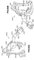
- Figure 22A illustrates the rotating side plate 2500 in a retaining configuration in which a portion of the rotating side plate 2500 proximate the first edge 2508 of the rotating side plate 2500 covers at least a portion of the side opening 2150 to the cable guide passage 2230.
- an elongated member (not shown in Figure 22A ) is retained in the cable guide passage 2230 of the cable guide 2231 of the housing 2200.
- the retaining configuration is achieved when the cutout section 2107 of the lock member 2106 is not aligned with the lock surface portion 2511 of the second edge 2510 of the rotating side plate 2500 as illustrated in Figure 22A .
- the lock member 2106 in this configuration engages the rotating side plate 2500 to maintain the rotating side plate 2500 in a static location in relation to the cable guide 2231.
- the lever biasing member 2138 biases the lock member 2106 in this configuration as discussed above.
- Figure 22B illustrates the rotating side plate 2500 in an open configuration. In this configuration, the cutout section 2107 of the lock member 2106 is aligned with the lock surface portion 2511 of the rotating side plate 2500. This allows the rotating side plate 2500 to pivot.
- the rope grab 2000 is designed so that a user can both rotate the levers 2700 and 2102 and pull back on the rotating side plate 2500 to put the rotating side plate 2500 in the open configuration with a single hand.
- an elongated member can be slid into or out of the cable passage 2230.
- the rotating side plate 2500 can be released to rotate the rotating side plate 2500 to the retaining position and the levers 2700 and 2102 can be released to engage the lock member 2106 to the rotating side plate 2500.
- FIGS 23A and 23B illustrate the rope grab 2000 in use after the elongated member 2914 or 2920, respectively have been positioned within the cable guide passage 2230 of the housing 2200.
- the elongated members 2914 or 2920 are guided through the cable guide passage 2230 formed by the cable guide 2231 with the upper roller 2114 and the lower roller 2134.
- the locking cam 2300 rotates to the open position under the influence of gravity, so a minimal (if any) frictional force is applied to the elongated member via the rope grab 2000.
- the rope grab 2000 in a normal non-fall event use, is relatively free to move up and down on the elongated member with the movement of the user who would be coupled to the locking arm 2400 via carabiner or other connecting means and safety harness (not shown).
- Figures 23A and 23B illustrate that the rope grab 2000 can be used on different sized elongated members 2914 and 2920.
- the portion of the radial engaging edge 2302 of the locking cam 2300 that engages the elongated member depends on the diameter of the elongated member 2914 and 2920.
- This movement of the locking cam 2300 forces the radial engaging edge 2302 of the locking cam 2300 to forcefully pinch a portion of the elongated member 2914 or 2920 between the radial edge 2302 of the locking cam 2300 and the cable guide 2231 of the housing 2200 therein locking movement of the rope grab 2000 in relation to the elongated member 2914 or 2920.
- the rope grab 2000 will remain locked onto the elongated member 2914 or 2920 until the downward force of the fallen user is removed.
- the gravitation forces on the cam lock 2300 are overcome by the light biasing force of the cam spring 2132 as well as by inertial forces, to also cause the cam lock 2300 to lock onto the elongated members 2914 or 2920.
Description
- Regulations typically require workers who work at heights to don a safety harness that is coupled to a support structure so that if a fall event occurs, the fall is limited, therein reducing the chances of injuries to the worker. Systems that protect workers during fall events that can occur while climbing or descending on structures such as ladders and the like, see for example
US 6 056 086 , can be a challenge because of the varying vertical locations of the worker in relation to a support structure. - For the reasons stated above and for other reasons stated below which will become apparent to those skilled in the art upon reading and understanding the present specification, there is a need in the art for an effective and efficient rope grab system that includes a rope grab and a generally vertically placed elongated member that is used as a support structure.
- The above-mentioned problems of current systems are addressed by embodiments of the present invention and will be understood by reading and studying the following specification. The following summary is made by way of example and not by way of limitation. It is merely provided to aid the reader in understanding some of the aspects of the invention.
- In one embodiment, a rope grab is provided. The rope grab includes a housing, a locking cam, a cam biasing member and a locking arm. The housing has an elongated member guide forming an elongated member passage. The elongated member passage is configured and arranged to receive an elongated member. The locking cam is pivotally coupled to the housing. The locking cam is configured and arranged to selectively engage an elongated member received in the elongated member passage. The cam biasing member positioned to provide a relatively slight biasing force on the locking cam towards an elongated member received in the elongated member passage. The locking arm is pivotally coupled to the housing. The locking arm has a first end that is configured and arranged to be coupled to a safety harness of a user and a second end that is configured and arranged to selectively engage the locking cam to lock the locking cam on an elongated member in the elongated member passage during a fall event.
- In still further another embodiment, a method of manipulating a rope grab is provided. The method includes rotating a lever rotationally coupled to a housing to release a rotating side plate with a hand of a user; pulling back on an end of the rotating side plate to pivot a portion of the rotating side plate away from a side opening to an elongated member passage formed in the housing with the hand of the user; positioning the rope grab to receive an elongated member within the elongated member passage of the housing with the hand of the user; and releasing the rotating side plate to allow the rotating side plate to at least partially cover the side opening to the elongated member passage of the housing to retain the elongated member with the elongated member passage.
- The present invention can be more easily understood and further advantages and uses thereof will be more readily apparent, when considered in view of the detailed description and the following figures in which:
-
Figure 1 is a side perspective view of a rope grab of one embodiment of the present invention; -
Figure 2 is an unassembled view of the rope grab ofFigure 1 ; -
Figure 3A is a first side view of a housing of the rope grab ofFigure 1 of one embodiment of the present invention; -
Figure 3B is a cross-sectional front view of the housing alongline 3B-3B ofFigure 3A ; -
Figure 3C is a second side view of a housing of the rope grab ofFigure 1 ; -
Figure 3D is a top view of the housing of the rope grab ofFigure 1 ; -
Figure 4A is a side view of a fixed side plate of one embodiment of the rope grab ofFigure 1 ; -
Figure 4B is a front view of the fixed side plate ofFigure 4A ; -
Figure 5A is a side view of a rotating side plate of one embodiment of the rope grab ofFigure 1 ; -
Figure 5B is a front view of the rotating side plate ofFigure 5A ; -
Figure 6A is a side perspective view of an arm spring of one embodiment of the rope grab ofFigure 1 ; -
Figure 6B is a side view of the arm spring ofFigure 6A ; -
Figure 6C is a top view of the arm spring ofFigure 6A ; -
Figure 7A is a side perspective view of a spring spacer of one embodiment of the rope grab ofFigure 1 ; -
Figure 7B is a side view of the spring spacer ofFigure 7A ; -
Figure 7C is a cross-sectional front view of the spring spacer alongline 7C-7C ofFigure 7B ; -
Figure 8A is a side perspective view of a first lever of one embodiment of the rope grab ofFigure 1 ; -
Figure 8B is a front view of the first lever ofFigure 8A ; -
Figure 9A is a side perspective view of a locking member of one embodiment of the rope grab ofFigure 1 ; -
Figure 9B is a first side view of the locking member ofFigure 9A ; -
Figure 9C is a second side view of the locking member ofFigure 9A ; -
Figure 10A is a side view of a locking arm of one embodiment of the rope grab ofFigure 1 with the rotating side plate in a locked position; -
Figure 10B is a side view of the locking arm ofFigure 10A with the rotating side plate in an unlocked position; -
Figure 11A is a side perspective view of a locking cam of one embodiment of the rope grab ofFigure 1 ; -
Figure 11B is another side perspective view of the locking cam ofFigure 11A ; -
Figure 11C is a side view of the locking cam ofFigure 11A ; -
Figure 11D is a second side view of the locking cam ofFigure 11A ; -
Figure 11E is a front view of the locking cam ofFigure 11A ; -
Figure 12A is a cross-sectional side view of a partial rope grab ofFigure 1 engaging a first elongated member of a first diameter; -
Figure 12B is another cross-sectional side view of a partial rope grab ofFigure 1 engaging a second elongated member of a second diameter; -
Figure 13A is a partial side view of a locking cam of one embodiment; -
Figure 13B is a close up view of a portion of a profile of a radial edge of the locking cam ofFigure 13A ; -
Figure 14A is a side perspective view of an assembled bypass bracket of one embodiment of the present invention; -
Figure 14B is a side unassembled view of the bypass bracket ofFigure 14A ; -
Figure 15A is a side perspective view of a bypass bracket of an embodiment of the present invention coupled to a support structure and a rope grab; -
Figure 15B is a side perspective view of the bypass bracket ofFigure 15A ; -
Figure 15C is a top view of the bypass bracket ofFigure 15A coupled to the support structure; -
Figure 16A is a first side perspective view of a rope grab of another embodiment of the present invention; -
Figure 16B is a second side perspective view of the rope grab ofFigure 16A ; -
Figure 16C is a rear perspective view of the rope grab ofFigure 16A ; -
Figure 17 is an unassembled side view of the rope grab ofFigure 16A ; -
Figure 18A is a side view of a locking arm of the rope grab ofFigure 16A with a rotating side plate in a locked position; -
Figure 18B is a side view of the locking arm of the rope grab ofFigure 16A with the rotating side plate in an unlocked position; -
Figure 19A is a cross-sectional side view of a partial rope grab ofFigure 16A engaging a first elongated member of a first diameter; -
Figure 19B is another cross-sectional side view of a partial rope grab ofFigure 16A engaging a second elongated member of a second diameter; -
Figure 20A is a first side perspective view of a rope grab of yet another embodiment of the present invention; -
Figure 20B is a second side perspective view of the rope grab ofFigure 20A ; -
Figure 21 is an unassembled side view of the rope grab ofFigure 20A ; -
Figure 22A is a side view of a locking arm of the rope grab ofFigure 20A with a rotating side plate in a locked position; -
Figure 22B is a side view of the locking arm of the rope grab ofFigure 20A with the rotating side plate in an unlocked position; -
Figure 23A is a cross-sectional side view of a partial rope grab ofFigure 20A engaging a first elongated member of a first diameter; and -
Figure 23B is another cross-sectional side view of a partial rope grab ofFigure 20A engaging a second elongated member of a second diameter. - In accordance with common practice, the various described features are not drawn to scale but are drawn to emphasize specific features relevant to the present invention. Reference characters denote like elements throughout Figures and text.
- In the following detailed description, reference is made to the accompanying drawings, which form a part hereof, and in which is shown by way of illustration specific embodiments in which the inventions may be practiced. These embodiments are described in sufficient detail to enable those skilled in the art to practice the invention, and it is to be understood that other embodiments may be utilized and that changes may be made without departing from the spirit and scope of the present invention. The following detailed description is, therefore, not to be taken in a limiting sense, and the scope of the present invention is defined only by the claims.
- Embodiments of the present invention provide a rope grab (cable grab) used for fall protection that can be easily manipulated with one hand to attach and detach the rope grab from an elongated member such as a rope, cable or the like used as a support structure. Embodiments of the rope grabs 100, 1000 and 2000 described herein are designed to be coupled to a safety harness donned by a user and to lock onto an elongated member during a fall event to limit the fall of the user. An embodiment of the
rope grab 100 is illustrated in the side perspective view ofFigure 1 and the exploded view of therope grab 100 inFigure 2 . Therope grab 100 includes ahousing 200, alocking cam 300, alocking arm 400, arotating side plate 500, and a fixedside plate 600. The lockingcam 300, the lockingarm 400 and therotating side plate 500 are pivotally coupled to thehousing 200 as further discussed below. The elements of therope grab 100 are first described and then the construction and operation of therope grab 100 are described. - The
housing 200 of therope grab 100 is further illustrated inFigures 3A through 3D . Thehousing 200 includes abody 202 that has afirst side 303a and asecond side 303b. Thebody 202 further has anupper end 202a and an opposedlower end 202b. Proximate theupper end 202a of thebody 200 is positioned an upper end wall portion 201a that extends generally perpendicular from thefirst side 303a of thebody 202. Proximate thelower end 202b of thebody 202 is positioned a lower end wall portion 201b that extends generally perpendicular from thefirst side 303a of thebody 202. Thebody 202 further has afirst side edge 202c and an opposedsecond side edge 202d. Proximate thefirst side edge 202c of thehousing 200 is acable guide 231 that extends from thefirst side 303a of thebody 202 in generally a C shape. Thecable guide 231 forms a cable guide passage 230 (or elongated member passage) that extends from proximate theupper end 202a to thelower end 202b of thebody 202. Proximate thelower end 202b of thebody 202 of thehousing 200 and proximate thefirst side 202c of thebody 202 of thehousing 200 is positioned a lowerroller rivet passage 240 that passes through thebody 202. Moreover, acentral post 204 extends generally perpendicular from thefirst side 303a of thebody 202. Thecentral post 204 is generally located at a mid-portion between theupper end 202a and thelower end 202b of thebody 202 towards thesecond side edge 202d of thebody 202 of thehousing 200. Thecentral post 204 includes a firstcentral post portion 204a, a secondcentral post portion 204b and thirdcentral post portion 204c. The first central post portion extends from thefirst side 303a of thebody 202. The secondcentral post portion 204b extends from the firstcentral post portion 204a and has a diameter that is less than a diameter of the firstcentral post portion 204a. The thirdcentral post portion 204c extends from the secondcentral post portion 204b and has a diameter that is less than the diameter of the secondcentral post portion 204b. Acentral post passage 206 passes through thecentral post 204. Surrounding thecentral post 204 is a camspring holding channel 218 that is formed in thefirst side 303a of thebody 202. Thecam holding channel 218 includes a circular portion 218a and an extendingleg portion 218b. In the embodiment shown, theleg portion 218b terminates in aspring retaining aperture 218c. - A
lever passage 212 passes through thebody 202 of thehousing 200 proximate thesecond side edge 202d and towards thelower end 202b of thebody 202. Thelever passage 212 is further positioned proximate thecentral post 204. Thelever passage 212 includes a circular portion 212a and an extendingportion 212b that extends from the circular portion 212a towards thelower end 202b of thebody 202 of thehousing 200. Proximate thelever passage 212 is aside wall portion 214 that extends generally perpendicular from thefirst side 303a of thebody 202 of thehousing 200. Theside wall portion 214 is further generally positioned between thecentral post 204 and thelever passage 212. Proximate theside wall portion 214 is amid-wall portion 216 that also generally extends perpendicular from thefirst side 303a of thebody 202 of thehousing 200. Themid wall portion 216 is also positioned proximate thelever passage 212. Further, a raisedportion 215 extends from thefirst side 303a of thebody 202 of thehousing 200. The raisedportion 215 extends from thefirst side 303a of thebody 202 around thelever passage 212. The height of the raisedportion 215 is less than a height of theside wall portion 214 and a height of themid wall portion 216. Thehousing 200 further includes alower post 208 that is positioned proximate thelower end 202b of thebody 202 of thehousing 200. Thelower post 208 extends from thefirst side 303a of thebody 202 and includes a centrallower post passage 210. In particular, thelower post 208 includes a firstlower post portion 208a that extends from thefirst side 303a of thebody 202 and a secondlower post portion 208b that extends from the firstlower post portion 208a. The secondlower post portion 208b has a diameter that is less than a diameter of the firstlower post portion 208a. Thehousing 200 also has anupper post 221 that extends from thefirst side 303a of thebody 202. Theupper post 221 is positioned proximate theupper end 202a of thebody 202 and includes anupper post passage 220. As illustrated inFigure 3C , a leverspring holding channel 211 is formed in thesecond side 303b of thebody 202 of thehousing 200 around a portion of thelever passage 212. Also illustrated inFigure 3C is alever stop 233 that extends from thesecond side 303b of thebody 202 of thehousing 200 proximate thelever passage 212. Thelever stop 233 is designed to stop rotation oflever 700 at a select orientation. - The fixed
side plate 600 is illustrated inFigures 4A and 4B . The fixed side plate includes anupper end 612 and an opposedlower end 614. The fixedside plate 600 further includes afirst edge 616 and an opposedsecond edge 618. The fixedside plate 600 further includes afirst side 602a and asecond side 602b. A first connectingpassage 606 passes through the fixedside plate 600 proximate theupper end 612 and thefirst edge 616. Asecond connection passage 608 passes through the fixedside plate 600 proximate thefirst edge 616 and thelower end 614. The fixedside plate 600 further includes athird connection passage 604 which is positioned generally at a mid-portion of the fixedside plate 600 and towards thesecond edge 618. As illustrated inFigures 4A and 4B , aspring spacer bulge 602c extends from thefirst side 602a of the fixedside plate 600 creating a depression in thesecond side 602b of the fixedside plate 600 to receive an end of thespring spacer 112 as discussed further below. Thethird connection passage 604 is centrally located within thespring bulge 602c of the fixedside plate 600. The fixedside plate 600 also includes alever passage 610 that is positioned proximate thesecond edge 618 of the fixedside plate 600 and between thethird connection passage 604 and thelower end 614 of the fixedside plate 600. As illustrated inFigure 4A , thesecond side edge 614, in this embodiment, has several edge extending portions that extend at select angles from each other so that thesecond side edge 614 conforms to the general shape of thesecond side edge 202d of thehousing 200. - Referring to
Figures 5A and 5B , arotating side plate 500 of one embodiment is illustrated. Therotating side plate 500 includes afirst edge 508 an opposedsecond edge 510. Therotating side plate 500 also includes anupper end 506 and an opposedlower end 504. Thefirst edge 508 includes a plurality ofedge portions first portion 508a extends from thelower end 504 to thesecond portion 508b. Thesecond portion 508b extends from thefirst portion 508a at a select angle. Athird portion 508c extends from thesecond portion 508b at a select angle. The first, second andthird portions rotating side plate 500 that selectively blocks access to thecable guide passage 230 of thehousing 200 as discussed further below. Afourth portion 508d extends from thethird portion 508c to theupper end 506. Thefourth portion 508d is generally curved forming generally a cutout section in therotating side plate 500 that is designed to selectively receive theupper post 221 of thehousing 200 when assembled. Thesecond side edge 510 also has a plurality ofedge portions first portion 510a extends from thelower end 504. Asecond portion 510b extends from thefirst portion 510a. Athird portion 510c extends from thesecond portion 510b. Afourth portion 510d extends from thethird portion 510c and afifth portion 510e extends from thefourth portion 510d. As illustrated inFigure 5A thethird portion 510c,fourth portion 510d and thefifth portion 510e form a cutout section in thesecond edge 510 of therotating side plate 500 that allows for movement of therotating side plate 500 in relation to thespring spacer 112 when therope grab 100 is assembled. Thesixth portion 510f extends from thefifth portion 510e at a select angle. Theseventh portion 510g extends between thesixth portion 510f and theupper end 506. Therotating side plate 500 further includes afirst side surface 502a and asecond side surface 502b. Proximate thelower end 504 and extending in a direction of thesecond side surface 502b of the rotating side plate is an extendingtab 502c. Therotating side plate 500 further includes apivot connection passage 512 positioned proximate thelower end 504 and aroller connection passage 514 positioned proximate theupper end 506. -
Figures 6A through 6C illustrate anarm spring 110 of one embodiment. Thearm spring 110 includes a central coiledportion 110a. The coiledportion 110a is positioned between a first end portion 110b and asecond end portion 110c. The first end portion 110b extends inward in relation to the coiledportion 110a. Thesecond end portion 110c extends in a direction away from the first end portion 110b and terminates in a bent holding end 111. Thesecond end portion 110c of thearm spring 110 is shaped to engage anarm spring groove 409 of thelocking arm 400 as discussed further below.Figures 7A through 7C illustrate aspring spacer 112 of one embodiment of the present invention. Thespring spacer 112 includes generally acylindrical body 112a having afirst end 113 and an opposedsecond end 114. Thebody 112a of thespring spacer 112 further includes acentral passage 115. In addition, aspring holding slot 112b is formed in thefirst end 113 of thespring spacer 112. Thespring holding slot 112b extends across thefirst end 113 of thespring spacer 112 such that it extends into a portion of thecentral passage 115. Moreover, thespring holding slot 112b is designed to receive the first end portion 110b of thearm spring 110 while the coiledportion 110a of thearm spring 110 is positioned around thecylindrical body 112a of thespring spacer 112. Thespring spacer 112 further includes abore 112c extending into thefirst end 113 of thecylindrical body 112a. The bore is used by a tool to put a required pre-wind on thearm spring 110 during assembly. -
Figures 8A through 8B illustrate afirst lever 700 of one embodiment of the present invention. Thefirst lever 700 includes astem 702 and anactivation knob 704. Thestem 702 includes afirst stem portion 702a and asecond stem portion 702b. Thefirst stem portion 702a extends between theactivation knob 704 and thesecond stem portion 702b. Thesecond stem portion 702b has a diameter that is less than the diameter of thefirst stem portion 702a. An engagingtab 710 centrally extends from a surface of thefirst stem portion 702a. A pair ofrotating locking tabs second stem portion 702b proximate thefirst stem portion 702a. Theactivation knob 704 includes afirst disk portion 704a which is coupled to an end of thefirst stem portion 702a and a second extendingportion 704b which extends away from thefirst disk portion 704a in a select direction. The second extendingportion 704b provides leverage to rotate thestem 702. Theactivation knob 704 further has a third extendingportion 704c that extends from the second extendingportion 704b towards thestem portion 702. The third extendingportion 704c is designed to selectively engage the lever stop 231 on thesecond side 303b of thehousing 200 when assembled.Figures 9A through 9C illustrate alock member 106 of one embodiment. Thelock member 106 includes acylindrical base member 106a and an extendingportion 106d that extends away from thecylindrical base member 106a proximate an end of thecylindrical base member 106a. Thelock member 106 has afirst side 107 and an opposedsecond side 109. Thecylindrical base member 106a includes alock member passage 106c and acutout section 106b that is positioned proximate thefirst side 107 of thelock member 106. Extendingportion 106d includes a lockspring holding channel 106e that is formed in thesecond side 109 of the lockingmember 106. The lockspring holding channel 106e extends across the width of the extendingportion 106d. The extendingportion 106d further includes a lockspring holding slot 106f in a side of the extendingportion 106d that extends a height of the extendingportion 106d. The lockspring holding slot 106f extends into the lockspring holding channel 106e. - Illustrations of the
locking arm 400 are provided at least inFigures 2 ,10A and 10B . The lockingarm 400 includes a locking armmain portion 402 and a locking armenergy absorber portion 404. The locking armmain portion 402 includes a mainlocking arm passage 412. In addition, a lockingarm extending portion 408 extends from the locking armmain portion 402 in a direction that is opposite a direction that the locking armenergy absorber portion 404 extends from the locking armmain portion 402. Anarm spring groove 409 is formed in an edge proximate a junction between the locking armmain portion 402 and the lockingarm energy absorber 404. The locking armenergy absorber portion 404 includes an energyabsorber connector passage 406 proximate a termination end of the locking armenergy absorber portion 404. The energyabsorber connection passage 406 is used to connect a safety harness (not shown) donned by a user to therope grab 100 as further discussed below. For example, in a typical application, a frontal D-ring of a safety harness would be coupled to theswivel connector 122 attached to theenergy absorber portion 404 of thelocking arm 400 via carabiner (not shown). During a fall event, the locking armenergy absorber portion 404 is designed to straighten out therein absorbing energy to prevent injuries to the user. - Referring to
Figures 11A through 11E one embodiment of alocking cam 300 is illustrated. The lockingcam 300 includes acam body 302. Thecam body 302 of thelocking cam 300 includes aconnection portion 302a and anengagement portion 302b. Thecam body 302 further includes a first side 301a and a second side 301b. Theconnection portion 302a of thecam body 302 includes acam passage 304. Proximate thecam passage 304 in theconnection portion 302a of thelocking cam 300 is a camspring holding portion 306 which includes acam spring passage 306b which extends through the lockingcam 300 and acam spring slot 306a which is formed in the first side 301a of thecam body 302. Thecam spring slot 306a leads to thecam spring passage 306b. In use, a portion of a cam spring 132 (a cam biasing member) illustrated inFigure 2 is received in the cam wholespring holding portion 306 as further described below. The first side 301a of thecam body 302 further includes a recessedportion 312 that is positioned proximate the camspring holding portion 306 and extending to an edge of thecam body 302. The recessedportion 312 provides room for movement of the holding end 111 of thesecond end portion 110c of thearm spring 110 engaging thelocking arm 400 when the rope grab is assembled. The engagingportion 302b of thelocking cam 300 extends from theconnection portion 302a. The width of the engagingportion 302b is greater than the width of theconnection portion 302a. In particular, the width of the engagingportion 302b extends wider than the width of theconnection portion 302a in the direction of the first side 301a of thecam body 302. The engagingportion 302b of thelocking cam 300 further terminates in aradial edge 302c. Theradial edge 302c extends generally radially aboutcam passage 304 with a varied radial configuration as described below. Theradial edge 302c has generally a concave surface with a plurality of extendinggripping tabs 310 that are designed to frictionally engage an elongated member. - The engaging
portion 302b of thelocking cam 300 further includes afirst side edge 320 and asecond side edge 321 that respectively extend from theconnection portion 302a to theradial edge 302c. Thesecond side edge 321 extends generally in a straight line from theconnection portion 302a to theradial edge 302c. Thefirst side edge 320 has a plurality of firstside edge portions side edge portion 320a extends from theconnection portion 302a in generally a perpendicular fashion. The second side edge portion 320b extends from the firstside edge portion 320a in generally a curved configuration. The thirdside edge portions 320c extends from the second side edge portion 320b in generally a straight line to theradial edge 302c. The lockingcam 300 further includes ahub portion 303 that extends around thecam passage 304 of theconnection portion 302a of thecam body 302. Thehub 303 extends out from the second side 301b of thecam body 302. The engagingportion 302b of thelocking cam 300 further includes athird edge 330 that defines the engagingportion 302b from theconnection portion 302a. Thethird edge 330 includes a lockingarm engaging surface 332. The extendingportion 408 of thelocking arm 400 engages the lockingarm engaging surface 332 of thelocking cam 300 during a fall event as the lockingarm 400 as further discussed below. - The construction of the
rope grab 100 is further described in view ofFigure 2 and the Figures described above. Acam spring 132 having a coiledsection 132a and afirst end 132b is received in the camspring holding channel 218 of thebody 202 of thehousing 200. In particular, the coiledsection 132a of thecam spring 132 is received in the circular portion 218a of the camspring holding channel 218 and thefirst end 132b of thecam spring 132 is received in theleg portion 218b of the camspring holding channel 218. This configuration retains a first end of thecam spring 132 in a static configuration in relation to thehousing 200. Afirst bearing 128 is positioned within thecam passage 304 of thelocking cam 300. Thecam passage 304 is then positioned around thefirst post portion 204a of thecentral post 204 of thehousing 200. Asecond end 132c of thecam spring 132 is passed through thecam spring passage 306b and received in thecam spring slot 306a of the camspring holding portion 306 of thelocking cam 300. This arrangement of thecam spring 132 provides a relatively light biasing force on thelocking cam 300 to rotate thelocking cam 300 towards an elongated member in theelongated member passage 230 of thehousing 200. This relatively light biasing force is countered by gravity in normal climbing operations which keeps thecam lock 300 from locking onto the elongated member. Hence during normal operations, therope grab 100 moves relatively freely up and down the elongated member. In a free fall (fall event), gravitational forces do not counteract the light biasing force of thecam spring 132 and thelocking cam 300 will lock onto the elongated member. Inertial loads on thelocking cam 300 during a fall also work in tandem with the light biasing force of thecam spring 132 to rotate thelocking cam 300 onto the elongated member. - A
second bearing 126 is positioned in the mainlocking arm passage 412 of thelocking arm 400. Themain locking passage 412 of the locking arm is then positioned around thesecond post portion 204b of thecentral post 204 of thehousing 200. Thespring spacer 112 is then positioned around thethird post portion 204c of thecentral post 204. The coiledportion 110a of thearm spring 110 is positioned around thespring spacer 112 while the first end portion 110b of thearm spring 110 is received in thespring holding slot 112b of thespring spacer 112. The first end portion 110b of thearm spring 110 is further received in the cut outsection 203 of thethird post portion 204c of thepost 204 of thehousing 200. This arrangement holds the first end portion 110b of thearm spring 110 in a static position in relation to thehousing 200. Thesecond end portion 110c of thearm spring 110 is received in thearm spring groove 409 of thelocking arm 400 to assert a biasing force on thelocking arm 400 in a locked position. A fastener, such asrivet 142 passing through thecentral post passage 206 of thecentral post 204 of thehousing 200 and thethird connector passage 604 of the fixedside plate 600 couples thehousing 200 to the fixedside plate 600. - A
lever spring 138 is positioned over thestem 702 of thefirst lever 700. Thestem 702 of thefirst lever 700 is in turn passed through thelever passage 212 of thehousing 200. A first end portion 138a of thelever spring 138 is received in a spring holding bore 705 in thefirst lever 700. A second end portion 138b of thelever spring 138 is positioned in a gap in thesecond side edge 214 of thehousing 200 so that a biasing force is exerted on thestem 702 of thefirst lever 700 in a desired direction. The extendingportion 212b of thelever passage 212 allows the engaging tab 710 (shown inFigure 8A ) extending from thestem 702 of thefirst lever 700 to pass through thelever passage 212. Once thestem 702 is passed through thelever passage 212 of thehousing 200, thelock spring 108 is positioned around thestem 702. Afirst end portion 108a of thelock spring 108 engages a portion of thesecond side wall 214 of thehousing 200 to hold thefirst end portion 108a of thelock spring 108 in a static location in relation to thehousing 200. Thestem 702 of thefirst lever 700 is then passed through thelock member passage 106c of thelock member 106. The engagingtab 710 of thestem 702 of thefirst lever 700 is received in the cut outsection 106b of thelock member 106 to lock the rotation of thestem 702 with the rotation of thelock member 106. Asecond end portion 108b of thelock spring 108 is received in the lockspring holding channel 106e of the extendingportion 106d of thelock member 106 to exert a biasing force on thelock member 106 in a desired direction. Thestem 702 is then further passed through thelever passage 610 in the fixedside plate 600. Awasher 104 and asecond lever 102 are then coupled on thesecond stem portion 702b of thestem 702. Thesecond lever 102 includes a stem connection passage 102c withopposed grooves 102a and 102b. Theopposed grooves 102a and 102b respectfully receive therotation locking tabs stem 702 of thefirst lever 700 to lock rotation of thesecond lever 102 to the rotation of thestem 702. - A first fastener 140 (first rivet) passing through the
upper post passage 220 of theupper post 221 of thehousing 200 and through thefirst connection passage 606 in the fixedside plate 600 and a second fastener 144 (second rivet) passing through thelower post passage 210 of thelower post 208 of thehousing 200 and through thesecond connection passage 608 in the fixedside plate 600 further couples thehousing 200 to the fixedside plate 600. Thesecond fastener 144 further passes through thepivot connection passage 512 of therotating side plate 500 to provide a pivot connection for therotating side plate 500. Therope grab 100 further includes anupper roller 114 and alower roller 134 to guide the elongated member through thecable guide channel 230 of thehousing 200. Theupper roller 114 is rotationally coupled to therotating side plate 500 viaupper roller rivet 116. Thelower roller 134 is rotationally coupled to thehousing 200 adjacent thecable guide 231 of thehousing 200 vialower rivet 136. - A
lifeline swivel connector 122 is coupled to theenergy absorbing portion 404 of thelocking arm 400 viaswivel pivot connector 118. In particular, theswivel lifeline connector 122 includes abase 121c with aconnection passage 121 and a pair of spacedarms passages swivel pivot connection 118 is passed through theconnection passage 121 of theswivel lifeline connector 122. Ahead portion 118c of theswivel pivot connection 118 has a diameter larger than the diameter of theconnection passage 121 of theswivel lifeline connector 122. The pair of spaced arms 118a and 118b have aligned swivelpivot connection passages 117. Arivet 120 passes through the aligned swivelpivot connection passages 117 and theconnection passage 406 of thelocking arm 400 to couple theswivel lifeline connector 122 to thelocking arm 400. Arivet 124 passed through the alignedpassages swivel lifeline connector 122 is used to couple a lifeline to therope grab 100. As discussed above, the lifeline would be coupled to a safety harness (not shown) donned by a user. - Referring to the partial views of the
rope grab 100 inFigures 10A and 10B the operation of therope grab 100 is discussed.Figure 10A illustrates therotating side plate 500 in a retaining configuration in which a portion of therotating side plate 500 proximate thefirst edge 508 of therotating side plate 500 covers at least a portion of theside opening 150 to thecable guide passage 230. In this configuration, an elongated member (not shown inFigure 10A ) is retained in thecable guide passage 230 of thecable guide 231 of thehousing 200. The retaining configuration is achieved when the extendingportion 106d of thelock member 106 engages thesecond edge portion 510b of thesecond edge 510 of therotating side plate 500 which retains therotating side plate 500 in a static location in relation to thecable guide 231. Thelock spring 108 biases thelock member 106 in this configuration.Figure 10B illustrates therotating side plate 500 in an open configuration. In this configuration, a portion of therotating side plate 500 proximate thefirst edge 508 of therotating side plate 500 is moved far enough away from thecable guide 231 to allow passage of an elongated member into and out of thecable guide passage 230 through theside opening 150 to thecable guide passage 230. To get therotating side plate 500 into this configuration, at least one of the first andsecond levers portion 106d of thelock member 106 away from thesecond edge portion 510b of thesecond edge 510 of therotating side plate 500. The biasing force from theside plate spring 130 engaging the extendingtab 502c biases therotating side plate 500 to the retaining configuration. Hence, therotating side plate 500 must be rotated by hand after at least one of thelevers rotating side plate 500 proximate theupper roller 114. Therope grab 100 is designed so that a user can both rotate one of thelevers rotating side plate 500 to put the rotating side plate in the open configuration with a single hand. Once in the open position, an elongated member can be slid into or out of thecable passage 230. Once the elongated member is positioned in or taken out of thecable passage 230, therotating side plate 500 can be released to rotate therotating side plate 500 to the retaining position and thelever lock member 106 to therotating side plate 500. - The partial cross-sectional side views of the
rope grab 100 ofFigure 12A and 12B illustrate therope grab 100 engaging two differentelongated members elongated members elongated members Figures 12A and 12B , but will have the same contact angle 720 (Alpha 1 and Alpha 2). That is, the curvature of theradial edge 302c of thelocking cam 300 is not constant in relation to thecentral post passage 206. The curvature varies so that thesame contact angle 720 between theradial edge 302c of thelocking cam 300 and thecable guide 231 of the housing is achieved for a range of diameters of the elongated members. Thecontact angle 720 is an angle that provides sufficient holding friction of therope grab 100 between theradial edge 302c of thelocking cam 300 and thecable guide 231 during a fall event. This is further discussed below. - The partial cross-sectional views in
Figures 12A and 12B illustrate therope grab 100 in use after theelongated member cable guide passage 230 of thehousing 200. As illustrated, theelongated members cable guide passage 230 formed by thecable guide 231 with theupper roller 114 and thelower roller 134. During normal use when the user is climbing or descending, the locking cam rotates to the open position under the influence of gravity, so a minimal (if any) frictional force is applied to the elongated member via therope grab 100. Hence, therope grab 100, in a normal non-fall event use, is relatively free to move up and down on the elongated member with the movement of the user who would be coupled to the locking arm via carabiner or other connecting means and safety harness (not shown).Figures 12A and 12B illustrate that in this embodiment during normal use, a portion of themid-side wall portion 216 of thebody 202 of thehousing 200 rests in the lockingarm engaging groove 410 of thelocking arm 400. - During a fall event, a user's frontal attachment to the user's harness that is coupled to the swivel connector 122 (which is in turn coupled to the locking arm 400) will pull the
locking arm 400 down, therein rotatinglocking arm 400 about thecentral post 204. This movement causes the extendingportion 408 of thelocking arm 400 to engage the lockingarm engaging surface 332 of thelocking cam 300 therein pivoting thelocking cam 300 also about thecentral post 204 of thehousing 200. This movement of thelocking cam 300 forces theradial edge 302c of thelocking cam 300 to forcefully pinch a portion of theelongated member radial edge 302c of thelocking cam 300 and thecable guide 231 of thehousing 200 therein locking movement of therope grab 100 in relation to theelongated member energy absorber portion 404 of thelocking arm 400 will straighten out to absorb energy and prevent injury to the user. Therope grab 100 will remain locked onto theelongated member cam lock 300 are overcome by the light biasing force of thecam spring 132 as well as by inertial forces, to also cause thecam lock 300 to lock onto theelongated members - Referring to
Figures 13A and 13B an explanation of achieving thesame contact angle 720 with different sizedelongated members radial edge 302c of thelocking cam 300 for a given contact angle 720 (Alpha 1 and Alpha 2 inFigures 12A and 12B ) is determined by dividing thelocking cam 300 into multiple thin slices separated byplanes 350 that are perpendicular to the profile of theradial edge 302c and pass through arotational axis 360 of thelocking cam 300. The profile of theradial edge 302c is generated by creatingedges 352 that maintain an angle 354 (Beta) between the profile of theradial edge 302c of thelocking cam 300 and theplanes 350 separating the thin slices of thelocking cam 300.Angle Beta 354 is equal to 90° - contact angle 702 (Alpha 1 or Alpha 2). - Embodiments of the present invention further includes a
bypass bracket 800 that is designed to be coupled to a support structure and to hold an elongated member that therope grab 100 is engaging in a generally static position. An example of abypass bracket 800 is illustrated inFigures 14A and 14B . Thebypass bracket 800 includes abase bracket 802. Thebase bracket 802 includes afirst section 802a and asecond section 802b. Thesecond section 802b generally extends from thefirst section 802a in a perpendicular fashion. Thefirst section 802a includes two spacedconnection apertures second section 802b of thebase bracket 802 includes afirst connection aperture 804a and asecond connection aperture 804b. Thebypass bracket 800 further includes aclamp member 810. This embodiment of theclamp member 810 is made from a plate that has a first side edge 810a and an opposably positionedsecond side edge 810b. Theclient member 810 further includes a top edge 810c and an opposably positionedbottom edge 810d. Theclamp member 810 further includes a centrally positionedupper connection aperture 812 that is positioned proximate the upper edge 810c of theclamp member 810. Theclamp member 810 also includes aslot 814 that extends in the first side edge 810a of theclamp member 810 proximate thelower edge 810d of theclamp member 810. In use, a support structure such as, but not limited to, a rung of a ladder is positioned between thefirst section 802a of thebase bracket 802 and theclamp member 810. Afastener 816a then passes through aconnection aperture 806a in thebase bracket 802 and theupper connection aperture 812 of theclamp plate member 810. A nut 818a is then threadably engaged to thefastener 816a to couple an upper portion of theclamp member 810 to thebase bracket 802. Similarly, afastener 816b is passed through aconnection aperture 806b of thebase bracket 802 and withinslot 814 ofclamp member 810.Nut 818b is then threadably engaged to thefastener 816b to couple a lower portion of theclamp member 810 to thebase bracket 802. - The
bypass bracket 800 further includes asleeve clip 820. Thesleeve clip 820 includes a first portion 820a that has first and second connection apertures 823 (only oneconnection aperture 823 is shown inFigure 14B ). The connection apertures 823 are aligned with the first andsecond connection apertures base bracket 802.Rivets respective connection apertures sleeve clip 820 to thebase bracket 802. Thesleeve clip 820 further includes asecond portion 820b that extends from the first portion 820a in generally a perpendicular fashion. Thesecond portion 820b includes holdingears ears portion 825. Thefirst holding ear 822a has a generally C-shaped configuration with its open side facing a first direction. Thesecond holding ear 822b is also in generally a C-shaped configuration with its open side facing a second direction that is generally opposite the first direction. Theears sleeve channel 821 that is formed from a first channel 821a formed by thefirst holding ear 822a and a second channel 821b formed by thesecond holding ear 822b. - A
sleeve 830 is used in conjunction with thebypass bracket 800. Thesleeve 830 has a tubular configuration with acentral passage 832. An elongated member (such aselongated member 920 shown inFigure 15A ) is received within the central passage. Thesleeve 830 further includes afirst recess section 831a and a second recessedsection 831b. The first andsecond recess sections sleeve 830 in an opposable fashion. The first and second recessedsections sleeve 830. In particular, thefirst recess portion 831a is configured to receive thefirst holding ear 822a of thesleeve clip 820 and the second recessedportion 831b is configured to receive thesecond holding ear 822b of thesleeve clip 820. In use, once thebypass bracket 800 is coupled to the support structure as described above, the sleeve 830 (having theelongated member 920 passing through its central passage 832) is tilted in relation to the receiving sleeve channel 821 (approximately 90 degrees) and positioned such that the mid-portion of thesleeve 830 is received in thespace 825 between the holdingears sleeve clip 820. Once the mid-portion of thesleeve 830 is positioned within thespace 825 between the holdingears sleeve clip 820, thesleeve 830 is tilted to align with the receivingsleeve channel 821 of thesleeve clip 820, therein allowing thefirst ear 822a of thesleeve clip 820 to be received in thefirst recess 831a of the sleeve and thesecond holding ear 822b to be received in thesecond recess 831b of thesleeve 830. This locks thesleeve 830 within thesleeve clip 820 of thebypass bracket 800. This design allows thebypass brackets 800 to be attached to support structures prior to the connection to theelongated member 920. - The
bypass bracket 800 is designed to hold theelongated member 920 stationary while not interfering with the function of therope grab 100. Referring toFigures 15A through 15C an illustration of this is provided. Thebypass bracket 800 in this embodiment, includes aclamp member 811 that has an edge with teeth 811a that are designed to grip thesupport structure 900.Figures 15A through 15C illustrate therope grab 100 as it is passing across thebypass bracket 800. The side view ofFigure 15B illustrates therope grab 100 without the fixedside plate 600 for illustration purposes. As illustrated thesleeve 830 that holds theelongated member 920 is received in thecable guide passage 230 of therope grab 100. The lockingcam 300 will allow it to pass unless a fall event occurs. If a fall event occurs when thesleeve 830 is within thecable guide passage 230, the lockingcam 300 will lock down on thesleeve 830. Since, thesleeve 830 is locked to thebypass bracket 800 therope grab 100 will remain stationary to limit the fall. In the top view illustrated inFigure 15C , how thebypass bracket 800 does not interfere with the function of therope grab 100 is shown. In particular, thesecond portion 820b of thesleeve clip 820 passes through the opening between therotating side plate 500 and thecable guide 231 of thehousing 200 to position thesleeve 830 andelongated member 920 within thecable guide passage 230 of therope grab 100. A system may include a plurality ofbypass brackets 800 to position asupport structure 920 in a desired location. - Another embodiment of a
rope grab 1000 is illustrated in theFigures 16A through 16C . In particular,Figure 16A illustrates a first side perspective view of therope grab 1000,Figure 16B illustrates a second side perspective view of therope grab 1000 andFigure 16C illustrates a rear perspective view of therope grab 1000. Further, an exploded first side view of therope grab 1000 is illustrated inFigure 17 . Similar to therope grab 100 described above,rope grab 1000 includes ahousing 1200, alocking cam 1300, alocking arm 1400, arotating side plate 1500, and a fixedside plate 1600. Thelocking cam 1300, thelocking arm 1400 and therotating side plate 1500 are pivotally coupled to thehousing 1200. - The
housing 1200 ofrope grab 1000 includesrear slot 1207 best shown inFigures 16C andFigure 17 . Alever 1700, as discussed below, extends through therear slot 1207 in this embodiment. Proximate a front first side edge of thehousing 1200 is acable guide 1231 that extends from a first side edge of thehousing 1200 in generally a C shape. Thecable guide 1231 forms a cable guide passage 1230 (or elongated member passage) that extends from proximate an upper end to a lower end of thehousing 1200. - Proximate the lower end of the
housing 1200 andcable guide 1231 is positioned lowerroller rivet passages 1240 that pass through thehousing 1200. Arivet 1142 passing through the lowerroller rivet passages 1240 rotationally couples alower roller 1134 to thehousing 1200. Acentral post 1204 extends generally perpendicular from the first side of thehousing 1200. Thecentral post 1204 is generally located at a mid-portion between an upper end and a lower end of thehousing 1200 towards a second side edge of thehousing 1200 similar tocentral post 204 ofrope grab 100 discussed above. Also similar to rope grab 100, thecam passage 1340 of thelocking cam 1300 as well as passages in thecam spring 1132, thefirst bearing 1128,washer 1119,second bearing 1117, the spring spacer 1112, thearm spring 1110 are all received around thecentral post 1204 of thehousing 1200. Thecentral post 1204 includes anend portion 1205 that is received in aconnection passage 1604 in the fixedside plate 1600 to couple thehousing 1200 to the fixedside plate 1600. As withrope grab 100 described above, thehousing 1200 includes a camspring holding channel 1218 that surrounds thecentral post 1204. Thecam holding channel 1218 includes a circular portion and an extending leg portion to hold a first side of thecam spring 1132. A second side of the spring engages thelocking cam 1300. This arrangement of thecam spring 1132 provides a relatively light biasing force on thelocking cam 1300 to rotate thelocking cam 1300 towards an elongated member (cable or rope) in theelongated member passage 1230 of thehousing 1200. This relatively light biasing force is countered by gravity in normal climbing operations which keeps thecam lock 1300 from locking onto the elongated member. Hence during normal operations, therope grab 1000 moves relatively freely up and down the elongated member. In a free fall (fall event), gravitational forces do not counteract the light biasing force of thecam spring 1132 and thelocking cam 1300 will lock onto the elongated member. Inertial loads on thelocking cam 1300 during a fall also work in tandem with the light biasing force of thecam spring 1132 to rotate thelocking cam 1300 onto the elongated member. - In
rope grab 1000, thelocking arm 1400 does not include an energy absorbing portion like lockingarm 400 described above.Locking arm 1400, however, does include a lockingarm extending portion 1408 and a connectingarm 1404. The lockingarm extending portion 1408 is designed to engage a portion of thelocking cam 1300 during a fall event to engage aradial edge 1302 into the elongated member as described above regarding lockingarm extending portion 408 and thelocking cam 300. The connectingarm 1404 includes a connectingaperture 1406 in which aconnector 1350 is attached. In particular, alifeline swivel connector 1122 is coupled to the connectingaperture 1406 of thelocking arm 1400 viaswivel pivot connector 1118. Theswivel lifeline connector 1122 includes a base with aconnection passage 1121 and a pair of spacedarms 1122a and 1122b with alignedpassages 1123a and 1123b. A pair of spacedarms 1118a and 1118b of aswivel pivot connector 1118 is passed through theconnection passage 1121 of theswivel lifeline connector 1122. Ahead portion 1118c of theswivel pivot connector 1118 has a diameter larger than the diameter of theconnection passage 1121 of theswivel lifeline connector 1122. The pair of spacedarms 1118a and 1118b have aligned swivelpivot connection passages rivet 1120 passes through the aligned swivelpivot connection passages connection passage 1406 of thelocking arm 1400 to couple theswivel lifeline connector 1122 to thelocking arm 1400. Arivet 1124 passed through the alignedpassages 1123a and 1123b of theswivel lifeline connector 1122 is used to couple a lifeline to therope grab 1000. Thecarabiner 1350 is selectively coupled to therivet 1124. Thecarabiner 1350 would be coupled to a safety harness (not shown) donned by a user. - The
second bearing 1117 is positioned in a main locking arm passage 1412 of thelocking arm 1400. The main locking passage 1412 of the locking arm is then positioned around thecentral post 1204 of thehousing 1200 as described above. The spring spacer 1112 is also positioned around another portion of thecentral post 1204. The coiled portion of thearm spring 1110 is positioned around the spring spacer 1112 while a first end portion 1110a of thearm spring 1110 is received in aspring holding slot 1112b of the spring spacer 1112. The first end portion 1110a of thearm spring 1110 is further received in a cut outsection 1203 of thecenter post 1204 of thehousing 1200. This arrangement holds the first end portion 1110a of thearm spring 1110 in a static position in relation to thehousing 1200. A second end portion 1110b of thearm spring 1110 is received in the arm spring groove 1409 of thelocking arm 1400 to assert a biasing force on thelocking arm 1400 in a locked position. - The
rotating side plate 1500 includes an upper portion with aroller passage 1514 and lower portion with apivot connection passage 1512. Theupper roller 1114 is rotationally coupled toside plate 1500 viapin 1116. Thepivot connection passage 1512 receives asecond post 1208 of thehousing 1200. Therotating side plate 1500 further includes afirst edge 1508 and an opposedsecond edge 1510. Therotating side plate 1500 further includes a first cut outsection 1533 that extends in from thesecond edge 1510 near the lower portion and a centrally located second cut outsection 1531 to reduce weight of therope grab 1000. Also included along thesecond edge 1510 of therotating side plate 1500 is alock surface portion 1511 and an extendingtab 1502. The first cut outsection 1533 is positioned between thelock surface portion 1511 and the extendingtab 1502. Aside plate spring 1130 is also received on asecond post 1208 of thehousing 1200. A biasing force from theside plate spring 1130 engaging the extendingtab 1502 biases therotating side plate 1500 to the retaining configuration. Therotating side plate 1500 must be rotated by hand after lever 1700 (discussed below) is rotated. This is done by pulling back on therotating side plate 1500 proximate theupper roller 1114. Once in the open position, an elongated member can be slid into or out of thecable passage 1230. Once the elongated member is positioned in or taken out of thecable passage 1230, therotating side plate 1500 can be released to rotate therotating side plate 1500 to the retaining position and thelever 1700 can be released to engage the lock member 1106 (discussed below) to therotating side plate 1500. - The
lever 1700 and an associatedlever biasing member 1109 are mounted on athird post 1211 extending from thehousing 1200. Thelever 1700 is rotationally mounted on thethird post 1211. Thelever biasing member 1109 biases thelever 1700 into a locked position with one end engaging thelever 1700 and another end engaging thehousing 1200. Thelock member 1106 and a lockmember biasing member 1108 are also mounted on thethird post 1211. The lockmember biasing member 1108 biases thelock member 1106 in a lock position so that alock portion 1107 of the lock member engages thelock surface portion 1511 of therotating side plate 1500. A raisedtab 1701 oflever 1700 is received in aslot 1105 of thelock member 1106 to rotate thelock portion 1107 of thelock member 1106 away from thelock surface portion 1511 of the rotating side plate when thelever 1700 is rotated. - Referring to the partial views of the
rope grab 1000 inFigures 18A and 18B a portion of the operation of therope grab 1000 is discussed.Figure 18A illustrates therotating side plate 1500 in a retaining configuration in which a portion of therotating side plate 1500 proximate thefirst edge 1508 of therotating side plate 1500 covers at least a portion of theside opening 1150 to thecable guide passage 1230. In this configuration, an elongated member (not shown inFigure 18A ) is retained in thecable guide passage 1230 of thecable guide 1231 of thehousing 1200. The retaining configuration is achieved when the extendingportion 1107 of thelock member 1106 engages thelock surface portion 1511 of thesecond edge 1510 of therotating side plate 1500 which retains therotating side plate 1500 in a static location in relation to thecable guide 1231. The lockmember biasing member 1108 biases thelock member 1106 in this configuration.Figure 18B illustrates therotating side plate 1500 in an open configuration. In this configuration, a portion of therotating side plate 1500 proximate thefirst edge 1508 of therotating side plate 1500 is moved far enough away from thecable guide 1231 to allow passage of an elongated member into and out of thecable guide passage 1230 through theside opening 1150 to thecable guide passage 1230. To get therotating side plate 1500 into this configuration in this embodiment,lever 1700 is rotated, which rotates the extendingportion 1107 of thelock member 1106 away from thelock surface portion 1511 of thesecond edge 1510 of therotating side plate 1500. The biasing force from theside plate spring 1130 engaging the extendingtab 1511 biases therotating side plate 1500 to the retaining configuration. Hence, therotating side plate 1500 must be rotated by hand afterlever 1700 is rotated. This is done by pulling back on therotating side plate 1500 proximate theupper roller 1114. Therope grab 1000 is designed so that a user can both rotate thelever 1700 and pull back on therotating side plate 1500 to put the rotating side plate in the open configuration with a single hand. Once in the open position, an elongated member can be slid into or out of thecable passage 1230. Once the elongated member is positioned in or taken out of thecable passage 1230, therotating side plate 1500 can be released to rotate therotating side plate 1500 to the retaining position and thelever 1700 can be released to engage thelock member 1106 to therotating side plate 1500. - The partial cross-sectional views in
Figures 19A and 19B illustrate therope grab 1000 in use after theelongated member cable guide passage 1230 of thehousing 1200. As illustrated, theelongated members cable guide passage 1230 formed by thecable guide 1231 with theupper roller 1114 and thelower roller 1134. During normal use when the user is climbing or descending, thelocking cam 1300 rotates to the open position under the influence of gravity, so a minimal (if any) frictional force is applied to the elongated member via therope grab 1000. Hence, therope grab 1000, in a normal non-fall event use, is relatively free to move up and down on the elongated member with the movement of the user who would be coupled to thelocking arm 1400 via carabiner or other connecting means and safety harness (not shown).Figures 19A and 19B illustrate that therope grab 1000 can be used on different sizedelongated members radial engaging edge 1302 of thelocking cam 1300 that engages the elongated member depends on the diameter of theelongated member - As with
rope grab 100, during a fall event withrope grab 1000, a user's frontal attachment to the user's harness that is coupled to thelocking arm 1400 will pull thelocking arm 1400 down, therein rotatinglocking arm 1400 about thecentral post 1204. This movement causes the extendingportion 1408 of thelocking arm 1400 to engage a lockingarm engaging surface 1332 of thelocking cam 1300 therein pivoting thelocking cam 1300 also about thecentral post 1204 of thehousing 1200. This movement of thelocking cam 1300 forces theradial engaging edge 1302 of thelocking cam 1300 to forcefully pinch a portion of theelongated member radial edge 1302 of thelocking cam 1300 and thecable guide 1231 of thehousing 1200 therein locking movement of therope grab 1000 in relation to theelongated member rope grab 1000 will remain locked onto theelongated member cam lock 1300 are overcome by the light biasing force of thecam spring 1132 as well as by inertial forces, to also cause thecam lock 1300 to lock onto theelongated members - Another embodiment of a
rope grab 2000 is illustrated in theFigures 20A and 20B . In particular,Figure 20A illustrates a first side perspective view of therope grab 2000,Figure 20B illustrated a second side perspective view of therope grab 2000. Further, an exploded first side view of therope grab 2000 is illustrated inFigure 21 . Similar to therope grab 100 described above,rope grab 2000 includes ahousing 2200, alocking cam 2300, alocking arm 2400, arotating side plate 2500, and a fixedside plate 2600. Thelocking cam 2300, thelocking arm 2400 and therotating side plate 2500 are pivotally coupled to thehousing 2200. - The
housing 2200 ofrope grab 2000 includes acable guide 2231 that extends from the first side edge of thehousing 2200 in generally a C shape. Thecable guide 2231 forms a cable guide passage 2230 (or elongated member passage) that extends from proximate an upper end to a lower end of thehousing 2200. Proximate the lower end of thehousing 2200 andcable guide 2231 is positioned lowerroller rivet passages 2340 that passes through thehousing 2200. Arivet 2142 passing through the lowerroller rivet passages 2340 rotationally couples alower roller 2134 to thehousing 2200. Acentral post 2204 extends generally perpendicular from the first side of thehousing 2200. Thecentral post 2204 is generally located at a mid-portion between an upper end and a lower end of thehousing 2200 towards a second side edge of thehousing 2200 similar tocentral post 204 ofcable grab 100 discussed above. Also similar tocable grab 100, thecam passage 2304 of thelocking cam 2300 as well as passages in thecam spring 2132, thefirst bearing 2128,second bearing 2117, thespring spacer 2112, thearm spring 2110 are all received around thecentral post 2204 of thehousing 2200. Thecentral post 2204 includes anend portion 2205 that is received in aconnection passage 2604 in the fixedside plate 2600 to couple thehousing 2200 to the fixedside plate 2600. As withrope grab 100 described above, thehousing 2200 includes a camspring holding channel 2218 that surrounds thecentral post 2204. Thecam holding channel 2218 includes a circular portion and an extending leg portion to hold a first side of thecam spring 2132. A second side of the spring engages thelocking cam 2300. This arrangement of thecam spring 2132 provides a relatively light biasing force on thelocking cam 2300 to rotate thelocking cam 2300 towards an elongated member (cable) in theelongated member passage 2230 of thehousing 2200. This relatively light biasing force is countered by gravity in normal climbing operations which keeps thecam lock 2300 from locking onto the elongated member. Hence, during normal operations, therope grab 2000 moves relatively freely up and down the elongated member. In a free fall (fall event), gravitational forces do not counteract the light biasing force of thecam spring 2132 and thelocking cam 2300 will lock onto the elongated member. Inertial loads on thelocking cam 2300 during a fall also work in tandem with the light biasing force of thecam spring 2132 to rotate thelocking cam 2300 onto the elongated member. - In
rope grab 2000, thelocking arm 2400 does not include an energy absorbing portion like lockingarm 400 described above.Locking arm 2400 does include a lockingarm extending portion 2408 and a connectingarm 2404. The lockingarm extending portion 2408 is designed to engage a portion of thelocking cam 2300 during a fall event to engage aradial edge 2302 into the elongated member as described above regarding the lockingarm extending portion 408 and thelocking cam 300. The connectingarm 2404 includes a connecting aperture 2406 in which aconnector 2350 is attached. In particular, alifeline swivel connector 2122 is coupled to the connecting aperture 2406 of thelocking arm 2400 viaswivel pivot connector 2118. Theswivel lifeline connector 2122 includes a base with aconnection passage 2121 and a pair of spacedarms passages 2123a and 2123b. A pair of spacedarms 2118a and 2118b of aswivel pivot connection 2118 is passed through theconnection passage 2121 of theswivel lifeline connector 2122. Ahead portion 2118c of theswivel pivot connection 2118 has a diameter larger than the diameter of theconnection passage 2121 of theswivel lifeline connector 2122. The pair of spacedarms 2118a and 2118b have aligned swivelpivot connection passages 2115a and 2115b. Arivet 2120 passes through the aligned swivelpivot connection passages 2115a and 2115b and the connection passage 2406 of thelocking arm 2400 to couple theswivel lifeline connector 2122 to thelocking arm 2400. Arivet 2124 passed through the alignedpassages 2123a and 2123b of theswivel lifeline connector 2122 is used to couple a lifeline to therope grab 2000. Thecarabiner 2350 is selectively coupled to therivet 2124. Thecarabiner 2350 would be coupled to a safety harness (not shown) donned by a user. - The
second bearing 2117 is positioned in a main locking arm passage 2412 of thelocking arm 2400. The main locking passage 2412 of the locking arm is then positioned around thecentral post 2204 of thehousing 2200 as described above. Thespring spacer 2112 is also positioned around another portion of thecentral post 2204. The coiled portion of thearm spring 2110 is positioned around thespring spacer 2112 while a first end portion 2110a of thearm spring 2110 is received in aspring holding slot 2112b of thespring spacer 2112. The first end portion 2110a of thearm spring 2110 is further received in a cut outsection 2203 of thecenter post 2204 of thehousing 2200. This arrangement holds the first end portion 2110a of thearm spring 2110 in a static position in relation to thehousing 2200. Asecond end portion 2110b of thearm spring 2110 is received in thearm spring groove 2409 of thelocking arm 2400 to assert a biasing force on thelocking arm 2400 in a locked position. - The
rotating slide plate 2500 includes an upper portion with aroller passage 2514 and lower portion with apivot connection passage 2512. Theupper roller 2114 is rotational coupled to slideplate 2500 viapin 2116. Thepivot connection passage 2512 receives atsecond post 2208 of thehousing 2200. Therotating slide plate 2500 further includes afirst edge 2508 and an opposedsecond edge 2510. Therotating side plate 2500 further includes a first cut outsection 2533 that extends in from thesecond edge 2510 near the lower portion and a centrally located second cut outsection 2531 to reduce weight of therope grab 2000. Also included in along thesecond edge 2510 of therotating side plate 2500 is alock surface portion 2511 and an extending tab 2502. The first cut outsection 2533 is positioned between thelock surface portion 2511 and the extending tab 2502. Aside plate spring 2108 is also received on asecond post 1208 of thehousing 2200. A biasing force from theside plate spring 2108 engaging the extending tab 2502 biases therotating side plate 2500 to the retaining configuration. Therotating side plate 2500 must be rotated by hand afterlever 2700 or 2102 (discussed below) is rotated. This is done by pulling back on therotating side plate 2500 proximate theupper roller 2114. Once in the open position, an elongated member can be slid into or out of thecable passage 2230. Once the elongated member is positioned in or taken out of thecable passage 2230, therotating side plate 2500 can be released to rotate therotating side plate 2500 to the retaining position and thelever rotating side plate 2500. - In this embodiment, the
first lever 2700 includes alever post 2701 that extends though afirst lever passage 2207 in thehousing 2200 and asecond lever passage 2607 in the fixedside plate 2600. Thesecond lever 2102 and awasher 2104 are mounted to an end of thelever post 2701. Hence, this embodiment has twolevers rope grab 2000. Alock member 2106 is also mounted on thelever post 2701. In particular, alock tab 2707 extending from thelever post 2701 is received in alock slot 2109 to lock the rotation of thelock member 2106 with the rotation of thelever post 2701. Thelock member 2106 engages thelock surface portion 2511 of therotating slide plate 2500 to lock therotating side plate 2500 to cover a side of thecable guide passage 2230 as discussed below. Thelock member 2106 includes acutout section 2107. When thelever post 2701 is rotated by rotating one of thelevers cutout section 2107 is aligned with thelock surface portion 2511 of therotating side plate 2500, therope grab 2000 is in an unlocked configuration and therotating slide plate 2500 can be moved as discussed below. Alever biasing member 2138 is received around thelever post 2701. Thelever biasing member 2138 has one end engaged to thehousing 2200 and another end engaged withlever 2700 to bias thelever post 2701 and theconnected lock member 2106 in a lock configuration where thecutout section 2107 of thelock member 2106 is not aligned with thelock surface portion 2511 of the rotating side plate. - Referring to the partial views of the
rope grab 2000 inFigures 22A and 22B a portion of the operation of therope grab 2000 is discussed.Figure 22A illustrates therotating side plate 2500 in a retaining configuration in which a portion of therotating side plate 2500 proximate thefirst edge 2508 of therotating side plate 2500 covers at least a portion of theside opening 2150 to thecable guide passage 2230. In this configuration, an elongated member (not shown inFigure 22A ) is retained in thecable guide passage 2230 of thecable guide 2231 of thehousing 2200. The retaining configuration is achieved when thecutout section 2107 of thelock member 2106 is not aligned with thelock surface portion 2511 of thesecond edge 2510 of therotating side plate 2500 as illustrated inFigure 22A . As illustrated, thelock member 2106 in this configuration engages therotating side plate 2500 to maintain therotating side plate 2500 in a static location in relation to thecable guide 2231. Thelever biasing member 2138 biases thelock member 2106 in this configuration as discussed above.Figure 22B illustrates therotating side plate 2500 in an open configuration. In this configuration, thecutout section 2107 of thelock member 2106 is aligned with thelock surface portion 2511 of therotating side plate 2500. This allows therotating side plate 2500 to pivot. When pivoted, a portion of therotating side plate 2500 proximate thefirst edge 2508 of therotating side plate 2500 is moved far enough away from thecable guide 2231 to allow passage of an elongated member into and out of thecable guide passage 2230 through theside opening 2150 to thecable guide passage 2230. To get therotating side plate 2500 into this configuration in this embodiment, one of thelevers lock member 2106 to align thecutout section 2107 with the lock surface portion. The biasing force from theside plate spring 2108 engaging the extending tab 2502 biases therotating side plate 2500 to the retaining configuration. Hence, therotating side plate 2500 must be rotated by hand after thelevers rotating side plate 2500 proximate theupper roller 2114. Therope grab 2000 is designed so that a user can both rotate thelevers rotating side plate 2500 to put therotating side plate 2500 in the open configuration with a single hand. Once in the open position, an elongated member can be slid into or out of thecable passage 2230. Once the elongated member is positioned in or taken out of thecable passage 2230, therotating side plate 2500 can be released to rotate therotating side plate 2500 to the retaining position and thelevers lock member 2106 to therotating side plate 2500. - The partial cross-sectional views in
Figures 23A and 23B illustrate therope grab 2000 in use after theelongated member 2914 or 2920, respectively have been positioned within thecable guide passage 2230 of thehousing 2200. As illustrated, theelongated members 2914 or 2920 are guided through thecable guide passage 2230 formed by thecable guide 2231 with theupper roller 2114 and thelower roller 2134. During normal use when the user is climbing or descending, thelocking cam 2300 rotates to the open position under the influence of gravity, so a minimal (if any) frictional force is applied to the elongated member via therope grab 2000. Hence, therope grab 2000, in a normal non-fall event use, is relatively free to move up and down on the elongated member with the movement of the user who would be coupled to thelocking arm 2400 via carabiner or other connecting means and safety harness (not shown).Figures 23A and 23B illustrate that therope grab 2000 can be used on different sizedelongated members 2914 and 2920. The portion of theradial engaging edge 2302 of thelocking cam 2300 that engages the elongated member depends on the diameter of theelongated member 2914 and 2920. - As with
rope grab 100, during a fall event withrope grab 2000, a user's frontal attachment to the user's harness that is coupled to thelocking arm 2400 will pull thelocking arm 2400 down, therein rotatinglocking arm 2400 about thecentral post 2204. This movement causes the extendingportion 2408 of thelocking arm 2400 to engage a lockingarm engaging surface 2332 of thelocking cam 2300 therein pivoting thelocking cam 2300 also about thecentral post 2204 of thehousing 2200. This movement of thelocking cam 2300 forces theradial engaging edge 2302 of thelocking cam 2300 to forcefully pinch a portion of theelongated member 2914 or 2920 between theradial edge 2302 of thelocking cam 2300 and thecable guide 2231 of thehousing 2200 therein locking movement of therope grab 2000 in relation to theelongated member 2914 or 2920. Therope grab 2000 will remain locked onto theelongated member 2914 or 2920 until the downward force of the fallen user is removed. As with other embodiments, also during a fall event, the gravitation forces on thecam lock 2300 are overcome by the light biasing force of thecam spring 2132 as well as by inertial forces, to also cause thecam lock 2300 to lock onto theelongated members 2914 or 2920. - Although specific embodiments have been illustrated and described herein, it will be appreciated by those of ordinary skill in the art that any arrangement, which is calculated to achieve the same purpose, may be substituted for the specific embodiment shown. This application is intended to cover any adaptations or variations of the present invention. Therefore, it is manifestly intended that this invention be limited only by the claims.
Claims (15)
- A rope grab comprising:a housing (200) having an elongated member guide forming an elongated member passage, the elongated member passage configured and arranged to receive an elongated member;a locking cam (300) pivotally coupled to the housing, the locking cam configured and arranged to selectively engage an elongated member received in the elongated member passage;a cam biasing member (132) positioned to provide a relatively slight biasing force on the locking cam towards an elongated member received in the elongated member passage, the relatively slight biasing force being countered by gravity during normal operations of the rope grab_to allow the rope grab to move both up and down on the elongated member without the locking cam locking onto the elongated member during normal operations while inertial loads on the locking cam and the slight biasing force of the cam biasing member during a fall event work in tandem to rotate the locking cam onto the elongated member to lock the locking cam onto the elongated member in the elongated member passage; anda locking arm (400) pivotally coupled to the housing, the locking arm having a first end configured and arranged to be coupled to a safety harness of a user and a second end configured and arranged to selectively engage the locking cam to selectively lock the locking cam onto the elongated member in the elongated member passage during a fall event.
- The rope grab of claim 1, further comprising:
a rotating side plate pivotally coupled to the housing to selectively block a side opening to the elongated member passage of the housing. - The rope grab of claim 2, further comprising:
a fixed side plate coupled to the housing, the locking cam, the locking arm and the rotating side plate positioned between the fixed side plate and the housing. - The rope grab of claim 1, further comprising:the locking cam having a radial edge that is configured and arranged to engage an elongated member, the radial edge having a curvature that varies in relation to a pivot connection to the housing so that the radial edge engages each elongated member at an contact angle that is the same even when different diameter elongated members are received in the elongated member passage of the housing.
- The rope grab of claim 1, further comprising:a fixed side plate coupled to the housing, the locking cam, the locking arm and the rotating side plate positioned between the fixed side plate and the housing;a spring spacer positioned between the locking arm and the fixed plate, the spacer having a spring holding slot formed in an end of the spacer; andan arm spring having a first end portion, a second end portion and a coiled portion positioned in between the first end portion and the second end portion, the coiled portion received around the spring spacer, the first end portion of the arm spring received in the spring holding slot of the spring spacer, the first end portion of the arm spring further engaging a portion of the housing, the second end portion of the arm spring engaging the locking arm to provide a biasing force on the locking arm.
- The rope grab of claim 5, wherein the housing includes a post with a cut out section, the spring spacer having a central passage, the post of the housing received in the central passage and the first end portion of the arm spring received in the cut out section of the post to engage the first end portion of the arm spring to the housing.
- The rope grab of claim 2, further comprising:
at least one roller coupled proximate an end of the rotating side plate, the at least one roller configured to guide an elongated member through the elongated member passage. - The rope grab of claim 2, further comprising:
a side plate spring coupled between the housing and the rotating side plate to provide a biasing force on the rotating side plate. - The rope grab of claim 2, further comprising;
at least one lever;
a lever spring coupled between the housing and the at least one lever to provide a biasing force on the at least one lever;
a lock member coupled to rotate in response to the rotation of the at least one lever, the lock member configured and arranged to selectively engage the rotating side plate to lock the rotating side plate in a static position in relation to the housing to selectively block at least a portion of the side opening to the elongated passage; and
a lock spring coupled between the housing and the rotating side plate to provide a biasing force on the rotating side plate. - The rope grab of claim 9, further comprising:
the lever extending through a slot in the housing. - The rope grab of claim 1, wherein the locking arm includes an energy absorbing portion configured and arranged to absorb energy during a fall event.
- A rope grab of claim 1, further comprising:
at least one bypass bracket configured and arranged to couple an elongated member to a support structure. - The rope grab of claim 12, wherein the bypass bracket further comprises:a base bracket configured and arranged to be coupled to the support structure;a sleeve clip coupled to the base bracket, the sleeve clip including spaced opposably faced first and second holding ears; anda tubular sleeve having a central passage and spaced first and second opposably positioned recesses formed in an outer surface of the sleeve, the first and second holding ears of the sleeve clip configured and arranged to selectively receive the respective first and second opposably positioned recess of the tubular sleeve.
- A method of manipulating a rope grab, the method comprising:rotating a lever rotationally coupled to a housing to release a rotating side plate with a hand of a user;pulling back on an end of the rotating side plate to pivot a portion of the rotating side plate away from a side opening to an elongated member passage formed in the housing with the hand of the user;positioning the rope grab to receive an elongated member within the elongated member passage of the housing with the hand of the user; andreleasing the rotating side plate to allow the rotating side plate to at least partially cover the side opening to the elongated member passage of the housing to retain the elongated member with the elongated member passage.
- The method of claim 14, further comprising:rotating a lever rotationally coupled to a housing to release a rotating side plate with a hand of the user;pulling back on an end of the rotating side plate to pivot a portion of the rotating side plate away from a side opening to an elongated member passage formed in the housing with the hand of the user;removing the elongated member from the elongated member passage of the housing with the hand of the user; andreleasing the rotating side plate to allow the rotating side plate to at least partially cover the side opening to the elongated member passage of the housing.
Applications Claiming Priority (3)
| Application Number | Priority Date | Filing Date | Title |
|---|---|---|---|
| US13/551,845 US9132297B2 (en) | 2012-07-18 | 2012-07-18 | Rope grab |
| US13/891,871 US9168402B2 (en) | 2012-07-18 | 2013-05-10 | Rope grab |
| PCT/US2013/050868 WO2014015026A2 (en) | 2012-07-18 | 2013-07-17 | Rope grab |
Publications (2)
| Publication Number | Publication Date |
|---|---|
| EP2877251A2 EP2877251A2 (en) | 2015-06-03 |
| EP2877251B1 true EP2877251B1 (en) | 2020-01-22 |
Family
ID=48877575
Family Applications (1)
| Application Number | Title | Priority Date | Filing Date |
|---|---|---|---|
| EP13742361.2A Active EP2877251B1 (en) | 2012-07-18 | 2013-07-17 | Rope grab |
Country Status (11)
| Country | Link |
|---|---|
| US (1) | US9168402B2 (en) |
| EP (1) | EP2877251B1 (en) |
| JP (1) | JP6426605B2 (en) |
| CN (1) | CN105263584B (en) |
| AU (1) | AU2013292646B2 (en) |
| BR (1) | BR112015001131B1 (en) |
| CA (1) | CA2877993C (en) |
| MX (1) | MX2015000802A (en) |
| RU (1) | RU2657412C2 (en) |
| SG (1) | SG11201500296WA (en) |
| WO (1) | WO2014015026A2 (en) |
Families Citing this family (37)
| Publication number | Priority date | Publication date | Assignee | Title |
|---|---|---|---|---|
| DE102012207223B3 (en) * | 2012-04-30 | 2013-09-26 | Bornack Gmbh & Co. Kg | safety device |
| US9132297B2 (en) * | 2012-07-18 | 2015-09-15 | D B Industries, Llc | Rope grab |
| US9168402B2 (en) * | 2012-07-18 | 2015-10-27 | D B Industries, Llc | Rope grab |
| US9623269B2 (en) * | 2013-03-14 | 2017-04-18 | Black Diamond Equipment, Ltd. | Systems for assisted braking belay with a cam-clutch mechanism |
| USD764258S1 (en) * | 2013-05-10 | 2016-08-23 | D B Industries, Llc | Housing of a rope grab |
| USD746125S1 (en) * | 2013-05-10 | 2015-12-29 | D B Industries, Llc | Fixed side plate of a rope grab |
| USD739212S1 (en) | 2013-05-10 | 2015-09-22 | D B Industries, Llc | Housing of a rope grab |
| FR3011475B1 (en) * | 2013-10-07 | 2016-03-04 | Simond Ets | DESCENDOR-INSURER AUTOBLOQUANT |
| CA2887034A1 (en) * | 2014-04-01 | 2015-10-01 | Buckingham Manufacturing Company, Inc. | Ladder fall protection system and fall arrester |
| EP3148653B1 (en) * | 2014-05-29 | 2020-10-21 | Honeywell International Inc. | Guided type fall arrester - force control |
| EP2982417B1 (en) * | 2014-08-04 | 2018-07-04 | Honeywell International Inc. | Deformable energy absorber with deformation indicator |
| US10583315B2 (en) * | 2015-04-07 | 2020-03-10 | Harken, Incorporated | High load descender with adaptive release linkage |
| US11660475B2 (en) | 2015-04-07 | 2023-05-30 | Harken, Incorporated | High load descender with adaptive release linkage |
| CA2928081C (en) * | 2015-04-24 | 2018-09-18 | Buckingham Manufacturing Company, Inc. | Cam assembly for use with pole climbing fall restriction device |
| US9604079B2 (en) | 2015-07-21 | 2017-03-28 | Merritt Arboreal Design, Inc. | On-rope work positioning device |
| WO2017030558A1 (en) * | 2015-08-18 | 2017-02-23 | Honeywell International Inc. | Shuttle for a climbing protection system |
| US9750959B2 (en) * | 2015-10-21 | 2017-09-05 | Msa Technology, Llc | Cable grab device |
| EP3402577A1 (en) | 2016-01-15 | 2018-11-21 | DALEKOVOD PROIZVODNJA d.o.o. | Fall arrester with torsional energy absorbing means |
| CN109069890B (en) * | 2016-03-23 | 2021-05-07 | 霍尼韦尔国际公司 | Shuttle for climbing protection system |
| ES2912180T3 (en) * | 2016-06-17 | 2022-05-24 | Buttercup Business Inc | Second generation binary path safety traversal system |
| CN106139449A (en) * | 2016-08-23 | 2016-11-23 | 国网浙江杭州市余杭区供电公司 | Safety |
| US10035028B1 (en) * | 2017-01-04 | 2018-07-31 | Mallory Safety+Supply | Emergency descender device |
| CA3058573A1 (en) * | 2017-03-31 | 2018-10-04 | 3M Innovative Properties Company | Fall protection equipment connection status and control |
| WO2018185614A1 (en) * | 2017-04-03 | 2018-10-11 | 3M Innovative Properties Company | Fall-protection apparatus with protective shroud and with sleeve assembly |
| US20190338593A1 (en) * | 2017-07-17 | 2019-11-07 | Safeworks, Llc | Integrated climb assist and fall arrest systems and methods |
| EP3727604B1 (en) * | 2017-12-19 | 2023-07-26 | 3M Innovative Properties Company | Top bracket for fall protection safety system |
| US10316585B1 (en) | 2017-12-22 | 2019-06-11 | Werner Co. | Strand grab and ladder including the same |
| USD889691S1 (en) | 2017-12-22 | 2020-07-07 | Werner Co. | Strand grab |
| DE102018102325B4 (en) * | 2018-02-01 | 2021-01-21 | Bornack Gmbh & Co. Kg | Safety device |
| CN109529218B (en) * | 2018-12-27 | 2023-11-21 | 济南奔速超伦机械设备有限公司 | Rope grab |
| CN212090567U (en) * | 2019-09-20 | 2020-12-08 | 中际联合(北京)科技股份有限公司 | Linkage operation assembly, anti-falling device and anti-falling system |
| EP3835619A1 (en) * | 2019-12-11 | 2021-06-16 | BAUERandMORE GmbH | Brake disc for a cable brake for cable clamping, cable brake for cable clamping and method for retrofitting a cable brake |
| US11406851B2 (en) | 2020-01-17 | 2022-08-09 | Honeywell International Inc. | Fall protection locking system |
| US11642554B2 (en) * | 2020-03-26 | 2023-05-09 | Honeywell International Inc. | Shock absorber for fall protection locking system |
| CA3176483A1 (en) | 2020-05-06 | 2021-11-11 | Exxonmobil Upstream Research Company | Geological reasoning with graph networks for hydrocarbon identification |
| US11781610B2 (en) | 2021-06-18 | 2023-10-10 | Cmc Rescue, Inc. | Systems for line device |
| US20230405365A1 (en) * | 2022-06-17 | 2023-12-21 | Werner Co. | Cable grab |
Family Cites Families (66)
| Publication number | Priority date | Publication date | Assignee | Title |
|---|---|---|---|---|
| US2561514A (en) * | 1949-04-12 | 1951-07-24 | Isaac D Houseman | Strand brake |
| US2606350A (en) | 1949-07-05 | 1952-08-12 | French Humboldt | Cable strain clamp |
| US3177543A (en) | 1962-11-14 | 1965-04-13 | Cecil D Fountain | Safety locking device |
| US3179994A (en) | 1964-01-22 | 1965-04-27 | Meyer Machine Inc | Safety appliance |
| US3811155A (en) * | 1972-06-21 | 1974-05-21 | L Stafford | Rope grab assembly |
| JPS5314074Y2 (en) * | 1972-08-30 | 1978-04-14 | ||
| US3852943A (en) * | 1973-08-27 | 1974-12-10 | Meyer Ind Inc | Portable safety clamp |
| US4071926A (en) | 1974-05-09 | 1978-02-07 | D. B. Enterprises, Inc. | Safety device for ladder climbers |
| US3876036A (en) | 1974-06-20 | 1975-04-08 | Db Enterprises | Rope grab safety device |
| GB1536354A (en) | 1976-07-08 | 1978-12-20 | Britax Ltd | Energy absorber |
| US4077094A (en) * | 1976-09-17 | 1978-03-07 | Swager William E | Clamping device for a rope, cable, annular bar, or the like |
| US4059871A (en) * | 1976-09-17 | 1977-11-29 | Swager William E | Clamping device with locking trigger arm |
| DE2810928A1 (en) | 1978-03-14 | 1979-09-27 | Moser Kurt | Fall prevention safety device on building roof - provides connection to wire cable by sliding clamping lock |
| DE2812073C3 (en) | 1978-03-20 | 1981-01-08 | Mittelmann & Co Armaturenwerk, 5603 Wuelfrath | Lifeline clamp |
| JPS55158751U (en) * | 1979-04-28 | 1980-11-14 | ||
| CH659299B (en) | 1983-01-17 | 1987-01-15 | ||
| US4521000A (en) * | 1983-06-06 | 1985-06-04 | Dodge Jr Cleveland E | Bypassing double action rope grip |
| US4542884A (en) | 1983-06-06 | 1985-09-24 | Dodge Jr Cleveland E | Removable double action rope grip |
| DE3426551A1 (en) | 1983-11-23 | 1985-05-30 | Virtaradat Oy, Helsinki | Damping device |
| DE3425947A1 (en) | 1984-07-13 | 1986-01-16 | Söll KG Industrieschmiede, 8670 Hof | SLED FOR A RISE PROTECTION DEVICE FOR CLIMBING A LADDER |
| US4560029A (en) * | 1984-08-29 | 1985-12-24 | Wgm Safety Corp. | Security device |
| US4657110A (en) * | 1984-12-10 | 1987-04-14 | D B Industries, Inc. | Inertia rope grab |
| DE3531391A1 (en) | 1985-09-03 | 1987-03-12 | Bornack Herbert Fa | Fall brake |
| DE8606240U1 (en) | 1986-03-07 | 1986-04-24 | Lorenz Hasenbach GmbH & Co KG, 6277 Bad Camberg | Fall protection runners for fall protection rails |
| GB8627320D0 (en) * | 1986-11-14 | 1986-12-17 | Latchways Ltd | Lockable load-transfer |
| US4791243A (en) | 1987-02-04 | 1988-12-13 | Anco Engineers, Inc. | Compact device for long stroke energy absorption |
| GB9011370D0 (en) | 1990-05-22 | 1990-07-11 | Barrow Hepburn Sala Ltd | Energy-absorbing bracket |
| US5156240A (en) * | 1991-05-31 | 1992-10-20 | Meyer Ostrobrod | Rope grab |
| US5146655A (en) * | 1991-10-29 | 1992-09-15 | Gibbs Peter E | Safety clamp appliance |
| US5265696A (en) * | 1992-01-31 | 1993-11-30 | D B Industries, Inc. | Ladder climbing safety clamp |
| FR2720283B1 (en) * | 1994-04-21 | 1996-08-23 | Froment Sa | Anti-fall device locks automatically on a safety rope. |
| GB2293193A (en) * | 1994-09-19 | 1996-03-20 | Latchways Ltd | Fall arrest device |
| DE29501716U1 (en) | 1995-02-03 | 1995-03-16 | Soell Gmbh | Fall arrest system |
| FR2736273A1 (en) * | 1995-07-03 | 1997-01-10 | Sk Sarl | MOBILE FALL PROTECTION FOR LOCKING SUPPORT |
| FR2751233B1 (en) * | 1996-07-16 | 1998-10-09 | Tractel Sa | AUTOMATIC FALL STOP DEVICE FOR PERSONNEL WORKING AT HEIGHT |
| DE29805788U1 (en) * | 1998-03-30 | 1998-07-30 | Soell Gmbh | Fall arrest system |
| FR2780656B1 (en) * | 1998-07-03 | 2001-08-03 | Dalloz Fall Prot | ANTI-FALL APPARATUS ON A VERTICAL CABLE |
| EP1338304B1 (en) | 1998-10-23 | 2004-09-15 | D B Industries, Inc. | Energy absorbing connector |
| DE29906047U1 (en) | 1999-04-01 | 1999-07-01 | Soell Gmbh | Fall arrester |
| DE29920850U1 (en) | 1999-11-29 | 2000-02-24 | Soell Gmbh | Fall arrest system |
| EP1248917B1 (en) | 1999-12-21 | 2007-03-14 | Keyguard Limited | Energy absorber |
| FR2804708B1 (en) | 2000-02-03 | 2002-03-15 | Dalloz Fall Prot | DEVICE FOR FIXING A LIFELINE AGAINST A WALL |
| US20020014370A1 (en) * | 2000-04-17 | 2002-02-07 | Casebolt Scott C. | Fall arrest methods and apparatus with u-joint connector |
| US6648101B2 (en) | 2001-05-24 | 2003-11-18 | Michael P. Kurtgis | Fall protection lanyard apparatus |
| DE20217045U1 (en) | 2002-11-05 | 2003-04-10 | Christian Dalloz Holding Deuts | Fold away ladder with climbing protection system, has side bars which can be pivoted relative to middle guide rail |
| GB2396195B (en) | 2002-12-03 | 2005-11-30 | Simon Louis Rood | Support post for a safety line |
| FR2857601B1 (en) | 2003-07-17 | 2005-11-18 | Rodolphe Argoud | SHOCK ABSORBER DEVICE FOR ANCHORING A LIFE LINE OR THE LIKE |
| DE20314230U1 (en) * | 2003-09-12 | 2003-11-06 | Christian Dalloz Holding Deuts | Fall arrester as part of a fall protection system for ladders and similar climbing routes |
| ES2389481T3 (en) * | 2003-10-21 | 2012-10-26 | Uniline Safety Systems Limited | Fall arrest device and system that incorporates the same |
| GB0328937D0 (en) | 2003-12-13 | 2004-01-14 | Checkmate Uk Ltd | Lifeline trolley |
| GB0426149D0 (en) | 2004-11-29 | 2004-12-29 | Rapid Rail Internat | Fall arrest |
| GB0510653D0 (en) | 2005-05-25 | 2005-06-29 | Rapid Rail Internat Ltd | Shock absorber |
| DE202005011338U1 (en) | 2005-07-15 | 2006-11-23 | Christian Dalloz Holding Deutschland Gmbh & Co. Kg | Catch device is part of climbing protection system for preventing user from falling from ladder, platform has connecting element connected to detent pawl |
| WO2007035263A1 (en) * | 2005-09-20 | 2007-03-29 | D B Industries, Inc. | Double locking snap hook |
| US8584797B2 (en) * | 2006-10-16 | 2013-11-19 | Honeywell Fall Protection Deutschland Gmbh & Co. Kg | Fall arrester for a climbing protection system |
| DE202007012804U1 (en) | 2007-09-13 | 2009-02-12 | Sperian Fall Protection Deutschland Gmbh & Co. Kg | Fall Protection System |
| CA2711113C (en) | 2008-02-06 | 2017-11-28 | Sperian Fall Protection Inc. | Energy absorbers, connectors and horizontal lifeline systems |
| US9272168B2 (en) | 2008-02-06 | 2016-03-01 | Honeywell International Inc. | Energy absorbers, connectors and horizontal lifeline systems |
| GB0816343D0 (en) * | 2008-09-06 | 2008-10-15 | Uniline Safety Systems Ltd | Fall arrest device |
| FR2938771B1 (en) * | 2008-11-27 | 2010-12-31 | Zedel | CAM BLOCKING DEVICE FOR FIXED ROPE INSURANCE |
| CN201412476Y (en) * | 2009-04-02 | 2010-02-24 | 青岛武晓集团有限公司 | Novel rope grabbing machine |
| US8720014B2 (en) * | 2009-06-02 | 2014-05-13 | Yasuharu Nagaki | Trigger grip |
| CN102575478B (en) * | 2009-10-23 | 2014-07-16 | Db工业股份有限公司 | Energy absorber |
| FR2962658B1 (en) | 2010-07-16 | 2012-07-13 | Tractel Sas | LIFESTYLE SYSTEM FOR FALL PROTECTION, SLIDER, CABLE BRACKET AND SLEEVE |
| US8733739B2 (en) * | 2011-03-21 | 2014-05-27 | Kirk Martin Mauthner | Device that integrates an ascender with a pulley block |
| US9168402B2 (en) * | 2012-07-18 | 2015-10-27 | D B Industries, Llc | Rope grab |
-
2013
- 2013-05-10 US US13/891,871 patent/US9168402B2/en active Active
- 2013-07-17 JP JP2015523221A patent/JP6426605B2/en not_active Expired - Fee Related
- 2013-07-17 EP EP13742361.2A patent/EP2877251B1/en active Active
- 2013-07-17 RU RU2014153262A patent/RU2657412C2/en active
- 2013-07-17 WO PCT/US2013/050868 patent/WO2014015026A2/en active Search and Examination
- 2013-07-17 CN CN201380037916.8A patent/CN105263584B/en active Active
- 2013-07-17 BR BR112015001131-4A patent/BR112015001131B1/en active IP Right Grant
- 2013-07-17 AU AU2013292646A patent/AU2013292646B2/en active Active
- 2013-07-17 SG SG11201500296WA patent/SG11201500296WA/en unknown
- 2013-07-17 MX MX2015000802A patent/MX2015000802A/en unknown
- 2013-07-17 CA CA2877993A patent/CA2877993C/en active Active
Non-Patent Citations (1)
| Title |
|---|
| None * |
Also Published As
| Publication number | Publication date |
|---|---|
| RU2657412C2 (en) | 2018-06-13 |
| BR112015001131B1 (en) | 2021-03-23 |
| AU2013292646A1 (en) | 2015-01-22 |
| US20140020988A1 (en) | 2014-01-23 |
| CN105263584B (en) | 2019-04-02 |
| CA2877993C (en) | 2020-08-25 |
| US9168402B2 (en) | 2015-10-27 |
| MX2015000802A (en) | 2015-05-08 |
| AU2013292646B2 (en) | 2017-07-06 |
| SG11201500296WA (en) | 2015-02-27 |
| BR112015001131A2 (en) | 2017-06-27 |
| JP2015531617A (en) | 2015-11-05 |
| CN105263584A (en) | 2016-01-20 |
| JP6426605B2 (en) | 2018-11-21 |
| WO2014015026A2 (en) | 2014-01-23 |
| CA2877993A1 (en) | 2014-01-23 |
| RU2014153262A (en) | 2016-09-10 |
| EP2877251A2 (en) | 2015-06-03 |
| WO2014015026A3 (en) | 2014-09-12 |
Similar Documents
| Publication | Publication Date | Title |
|---|---|---|
| EP2877251B1 (en) | Rope grab | |
| US9636528B2 (en) | Rope grab | |
| EP2506937B1 (en) | Self-retracting lifeline with disconnectable lifeline | |
| US9273717B2 (en) | Connector for lifelines | |
| US20170274230A1 (en) | Snap hook | |
| EP3307399B1 (en) | D-ring keeper assembly | |
| EP2796172B1 (en) | Fall arrest device | |
| US6899203B1 (en) | Rope management apparatus | |
| EP3337987B1 (en) | Carabiner divider and fall arrest system | |
| EP1666104A1 (en) | Device for hanging and locking climbing ropes | |
| EP1596941B1 (en) | Safety devices | |
| US20100294590A1 (en) | Method, Apparatus, and Arrangement for a Lifeline System | |
| US20170050055A1 (en) | Auto-Blocking Rappelling and Belaying Device | |
| EP3001047B1 (en) | Carabiner | |
| GB2441140A (en) | Rope grab | |
| US9149667B2 (en) | Safety device | |
| MX2008008436A (en) | Slidable beam anchor |
Legal Events
| Date | Code | Title | Description |
|---|---|---|---|
| PUAI | Public reference made under article 153(3) epc to a published international application that has entered the european phase |
Free format text: ORIGINAL CODE: 0009012 |
|
| 17P | Request for examination filed |
Effective date: 20150116 |
|
| AK | Designated contracting states |
Kind code of ref document: A2 Designated state(s): AL AT BE BG CH CY CZ DE DK EE ES FI FR GB GR HR HU IE IS IT LI LT LU LV MC MK MT NL NO PL PT RO RS SE SI SK SM TR |
|
| AX | Request for extension of the european patent |
Extension state: BA ME |
|
| DAX | Request for extension of the european patent (deleted) | ||
| GRAP | Despatch of communication of intention to grant a patent |
Free format text: ORIGINAL CODE: EPIDOSNIGR1 |
|
| STAA | Information on the status of an ep patent application or granted ep patent |
Free format text: STATUS: GRANT OF PATENT IS INTENDED |
|
| INTG | Intention to grant announced |
Effective date: 20190816 |
|
| GRAS | Grant fee paid |
Free format text: ORIGINAL CODE: EPIDOSNIGR3 |
|
| GRAA | (expected) grant |
Free format text: ORIGINAL CODE: 0009210 |
|
| STAA | Information on the status of an ep patent application or granted ep patent |
Free format text: STATUS: THE PATENT HAS BEEN GRANTED |
|
| AK | Designated contracting states |
Kind code of ref document: B1 Designated state(s): AL AT BE BG CH CY CZ DE DK EE ES FI FR GB GR HR HU IE IS IT LI LT LU LV MC MK MT NL NO PL PT RO RS SE SI SK SM TR |
|
| REG | Reference to a national code |
Ref country code: GB Ref legal event code: FG4D |
|
| REG | Reference to a national code |
Ref country code: CH Ref legal event code: EP |
|
| REG | Reference to a national code |
Ref country code: AT Ref legal event code: REF Ref document number: 1226540 Country of ref document: AT Kind code of ref document: T Effective date: 20200215 |
|
| REG | Reference to a national code |
Ref country code: IE Ref legal event code: FG4D |
|
| REG | Reference to a national code |
Ref country code: DE Ref legal event code: R096 Ref document number: 602013065295 Country of ref document: DE |
|
| REG | Reference to a national code |
Ref country code: NL Ref legal event code: MP Effective date: 20200122 |
|
| REG | Reference to a national code |
Ref country code: LT Ref legal event code: MG4D |
|
| PG25 | Lapsed in a contracting state [announced via postgrant information from national office to epo] |
Ref country code: PT Free format text: LAPSE BECAUSE OF FAILURE TO SUBMIT A TRANSLATION OF THE DESCRIPTION OR TO PAY THE FEE WITHIN THE PRESCRIBED TIME-LIMIT Effective date: 20200614 Ref country code: FI Free format text: LAPSE BECAUSE OF FAILURE TO SUBMIT A TRANSLATION OF THE DESCRIPTION OR TO PAY THE FEE WITHIN THE PRESCRIBED TIME-LIMIT Effective date: 20200122 Ref country code: NL Free format text: LAPSE BECAUSE OF FAILURE TO SUBMIT A TRANSLATION OF THE DESCRIPTION OR TO PAY THE FEE WITHIN THE PRESCRIBED TIME-LIMIT Effective date: 20200122 Ref country code: RS Free format text: LAPSE BECAUSE OF FAILURE TO SUBMIT A TRANSLATION OF THE DESCRIPTION OR TO PAY THE FEE WITHIN THE PRESCRIBED TIME-LIMIT Effective date: 20200122 Ref country code: NO Free format text: LAPSE BECAUSE OF FAILURE TO SUBMIT A TRANSLATION OF THE DESCRIPTION OR TO PAY THE FEE WITHIN THE PRESCRIBED TIME-LIMIT Effective date: 20200422 |
|
| PG25 | Lapsed in a contracting state [announced via postgrant information from national office to epo] |
Ref country code: BG Free format text: LAPSE BECAUSE OF FAILURE TO SUBMIT A TRANSLATION OF THE DESCRIPTION OR TO PAY THE FEE WITHIN THE PRESCRIBED TIME-LIMIT Effective date: 20200422 Ref country code: SE Free format text: LAPSE BECAUSE OF FAILURE TO SUBMIT A TRANSLATION OF THE DESCRIPTION OR TO PAY THE FEE WITHIN THE PRESCRIBED TIME-LIMIT Effective date: 20200122 Ref country code: LV Free format text: LAPSE BECAUSE OF FAILURE TO SUBMIT A TRANSLATION OF THE DESCRIPTION OR TO PAY THE FEE WITHIN THE PRESCRIBED TIME-LIMIT Effective date: 20200122 Ref country code: HR Free format text: LAPSE BECAUSE OF FAILURE TO SUBMIT A TRANSLATION OF THE DESCRIPTION OR TO PAY THE FEE WITHIN THE PRESCRIBED TIME-LIMIT Effective date: 20200122 Ref country code: GR Free format text: LAPSE BECAUSE OF FAILURE TO SUBMIT A TRANSLATION OF THE DESCRIPTION OR TO PAY THE FEE WITHIN THE PRESCRIBED TIME-LIMIT Effective date: 20200423 Ref country code: IS Free format text: LAPSE BECAUSE OF FAILURE TO SUBMIT A TRANSLATION OF THE DESCRIPTION OR TO PAY THE FEE WITHIN THE PRESCRIBED TIME-LIMIT Effective date: 20200522 |
|
| REG | Reference to a national code |
Ref country code: DE Ref legal event code: R097 Ref document number: 602013065295 Country of ref document: DE |
|
| PG25 | Lapsed in a contracting state [announced via postgrant information from national office to epo] |
Ref country code: SM Free format text: LAPSE BECAUSE OF FAILURE TO SUBMIT A TRANSLATION OF THE DESCRIPTION OR TO PAY THE FEE WITHIN THE PRESCRIBED TIME-LIMIT Effective date: 20200122 Ref country code: SK Free format text: LAPSE BECAUSE OF FAILURE TO SUBMIT A TRANSLATION OF THE DESCRIPTION OR TO PAY THE FEE WITHIN THE PRESCRIBED TIME-LIMIT Effective date: 20200122 Ref country code: RO Free format text: LAPSE BECAUSE OF FAILURE TO SUBMIT A TRANSLATION OF THE DESCRIPTION OR TO PAY THE FEE WITHIN THE PRESCRIBED TIME-LIMIT Effective date: 20200122 Ref country code: ES Free format text: LAPSE BECAUSE OF FAILURE TO SUBMIT A TRANSLATION OF THE DESCRIPTION OR TO PAY THE FEE WITHIN THE PRESCRIBED TIME-LIMIT Effective date: 20200122 Ref country code: CZ Free format text: LAPSE BECAUSE OF FAILURE TO SUBMIT A TRANSLATION OF THE DESCRIPTION OR TO PAY THE FEE WITHIN THE PRESCRIBED TIME-LIMIT Effective date: 20200122 Ref country code: LT Free format text: LAPSE BECAUSE OF FAILURE TO SUBMIT A TRANSLATION OF THE DESCRIPTION OR TO PAY THE FEE WITHIN THE PRESCRIBED TIME-LIMIT Effective date: 20200122 Ref country code: EE Free format text: LAPSE BECAUSE OF FAILURE TO SUBMIT A TRANSLATION OF THE DESCRIPTION OR TO PAY THE FEE WITHIN THE PRESCRIBED TIME-LIMIT Effective date: 20200122 Ref country code: DK Free format text: LAPSE BECAUSE OF FAILURE TO SUBMIT A TRANSLATION OF THE DESCRIPTION OR TO PAY THE FEE WITHIN THE PRESCRIBED TIME-LIMIT Effective date: 20200122 |
|
| REG | Reference to a national code |
Ref country code: AT Ref legal event code: MK05 Ref document number: 1226540 Country of ref document: AT Kind code of ref document: T Effective date: 20200122 |
|
| PLBE | No opposition filed within time limit |
Free format text: ORIGINAL CODE: 0009261 |
|
| STAA | Information on the status of an ep patent application or granted ep patent |
Free format text: STATUS: NO OPPOSITION FILED WITHIN TIME LIMIT |
|
| 26N | No opposition filed |
Effective date: 20201023 |
|
| PG25 | Lapsed in a contracting state [announced via postgrant information from national office to epo] |
Ref country code: AT Free format text: LAPSE BECAUSE OF FAILURE TO SUBMIT A TRANSLATION OF THE DESCRIPTION OR TO PAY THE FEE WITHIN THE PRESCRIBED TIME-LIMIT Effective date: 20200122 Ref country code: IT Free format text: LAPSE BECAUSE OF FAILURE TO SUBMIT A TRANSLATION OF THE DESCRIPTION OR TO PAY THE FEE WITHIN THE PRESCRIBED TIME-LIMIT Effective date: 20200122 |
|
| PG25 | Lapsed in a contracting state [announced via postgrant information from national office to epo] |
Ref country code: PL Free format text: LAPSE BECAUSE OF FAILURE TO SUBMIT A TRANSLATION OF THE DESCRIPTION OR TO PAY THE FEE WITHIN THE PRESCRIBED TIME-LIMIT Effective date: 20200122 Ref country code: SI Free format text: LAPSE BECAUSE OF FAILURE TO SUBMIT A TRANSLATION OF THE DESCRIPTION OR TO PAY THE FEE WITHIN THE PRESCRIBED TIME-LIMIT Effective date: 20200122 Ref country code: MC Free format text: LAPSE BECAUSE OF FAILURE TO SUBMIT A TRANSLATION OF THE DESCRIPTION OR TO PAY THE FEE WITHIN THE PRESCRIBED TIME-LIMIT Effective date: 20200122 |
|
| REG | Reference to a national code |
Ref country code: CH Ref legal event code: PL |
|
| GBPC | Gb: european patent ceased through non-payment of renewal fee |
Effective date: 20200717 |
|
| REG | Reference to a national code |
Ref country code: BE Ref legal event code: MM Effective date: 20200731 |
|
| PG25 | Lapsed in a contracting state [announced via postgrant information from national office to epo] |
Ref country code: CH Free format text: LAPSE BECAUSE OF NON-PAYMENT OF DUE FEES Effective date: 20200731 Ref country code: LI Free format text: LAPSE BECAUSE OF NON-PAYMENT OF DUE FEES Effective date: 20200731 Ref country code: GB Free format text: LAPSE BECAUSE OF NON-PAYMENT OF DUE FEES Effective date: 20200717 Ref country code: FR Free format text: LAPSE BECAUSE OF NON-PAYMENT OF DUE FEES Effective date: 20200731 Ref country code: LU Free format text: LAPSE BECAUSE OF NON-PAYMENT OF DUE FEES Effective date: 20200717 |
|
| PG25 | Lapsed in a contracting state [announced via postgrant information from national office to epo] |
Ref country code: BE Free format text: LAPSE BECAUSE OF NON-PAYMENT OF DUE FEES Effective date: 20200731 |
|
| PG25 | Lapsed in a contracting state [announced via postgrant information from national office to epo] |
Ref country code: IE Free format text: LAPSE BECAUSE OF NON-PAYMENT OF DUE FEES Effective date: 20200717 |
|
| PG25 | Lapsed in a contracting state [announced via postgrant information from national office to epo] |
Ref country code: TR Free format text: LAPSE BECAUSE OF FAILURE TO SUBMIT A TRANSLATION OF THE DESCRIPTION OR TO PAY THE FEE WITHIN THE PRESCRIBED TIME-LIMIT Effective date: 20200122 Ref country code: MT Free format text: LAPSE BECAUSE OF FAILURE TO SUBMIT A TRANSLATION OF THE DESCRIPTION OR TO PAY THE FEE WITHIN THE PRESCRIBED TIME-LIMIT Effective date: 20200122 Ref country code: CY Free format text: LAPSE BECAUSE OF FAILURE TO SUBMIT A TRANSLATION OF THE DESCRIPTION OR TO PAY THE FEE WITHIN THE PRESCRIBED TIME-LIMIT Effective date: 20200122 |
|
| PG25 | Lapsed in a contracting state [announced via postgrant information from national office to epo] |
Ref country code: MK Free format text: LAPSE BECAUSE OF FAILURE TO SUBMIT A TRANSLATION OF THE DESCRIPTION OR TO PAY THE FEE WITHIN THE PRESCRIBED TIME-LIMIT Effective date: 20200122 Ref country code: AL Free format text: LAPSE BECAUSE OF FAILURE TO SUBMIT A TRANSLATION OF THE DESCRIPTION OR TO PAY THE FEE WITHIN THE PRESCRIBED TIME-LIMIT Effective date: 20200122 |
|
| P01 | Opt-out of the competence of the unified patent court (upc) registered |
Effective date: 20230530 |
|
| PGFP | Annual fee paid to national office [announced via postgrant information from national office to epo] |
Ref country code: DE Payment date: 20230620 Year of fee payment: 11 |