EP2877251B1 - Seilgreifer - Google Patents
Seilgreifer Download PDFInfo
- Publication number
- EP2877251B1 EP2877251B1 EP13742361.2A EP13742361A EP2877251B1 EP 2877251 B1 EP2877251 B1 EP 2877251B1 EP 13742361 A EP13742361 A EP 13742361A EP 2877251 B1 EP2877251 B1 EP 2877251B1
- Authority
- EP
- European Patent Office
- Prior art keywords
- housing
- side plate
- elongated member
- passage
- rope grab
- Prior art date
- Legal status (The legal status is an assumption and is not a legal conclusion. Google has not performed a legal analysis and makes no representation as to the accuracy of the status listed.)
- Active
Links
- 125000006850 spacer group Chemical group 0.000 claims description 30
- 230000003068 static effect Effects 0.000 claims description 10
- 210000005069 ears Anatomy 0.000 claims description 7
- 230000005484 gravity Effects 0.000 claims description 7
- 238000000034 method Methods 0.000 claims description 5
- 230000036961 partial effect Effects 0.000 description 14
- 239000006096 absorbing agent Substances 0.000 description 10
- 230000009194 climbing Effects 0.000 description 7
- 230000004913 activation Effects 0.000 description 4
- 208000027418 Wounds and injury Diseases 0.000 description 3
- 230000006378 damage Effects 0.000 description 3
- 208000014674 injury Diseases 0.000 description 3
- 230000000717 retained effect Effects 0.000 description 3
- 238000010276 construction Methods 0.000 description 2
- KJLPSBMDOIVXSN-UHFFFAOYSA-N 4-[4-[2-[4-(3,4-dicarboxyphenoxy)phenyl]propan-2-yl]phenoxy]phthalic acid Chemical compound C=1C=C(OC=2C=C(C(C(O)=O)=CC=2)C(O)=O)C=CC=1C(C)(C)C(C=C1)=CC=C1OC1=CC=C(C(O)=O)C(C(O)=O)=C1 KJLPSBMDOIVXSN-UHFFFAOYSA-N 0.000 description 1
- 230000006978 adaptation Effects 0.000 description 1
- 230000002452 interceptive effect Effects 0.000 description 1
- 230000000670 limiting effect Effects 0.000 description 1
Images


Classifications
-
- A—HUMAN NECESSITIES
- A62—LIFE-SAVING; FIRE-FIGHTING
- A62B—DEVICES, APPARATUS OR METHODS FOR LIFE-SAVING
- A62B35/00—Safety belts or body harnesses; Similar equipment for limiting displacement of the human body, especially in case of sudden changes of motion
- A62B35/0081—Equipment which can travel along the length of a lifeline, e.g. travelers
-
- A—HUMAN NECESSITIES
- A62—LIFE-SAVING; FIRE-FIGHTING
- A62B—DEVICES, APPARATUS OR METHODS FOR LIFE-SAVING
- A62B1/00—Devices for lowering persons from buildings or the like
- A62B1/06—Devices for lowering persons from buildings or the like by making use of rope-lowering devices
- A62B1/14—Devices for lowering persons from buildings or the like by making use of rope-lowering devices with brakes sliding on the rope
-
- A—HUMAN NECESSITIES
- A62—LIFE-SAVING; FIRE-FIGHTING
- A62B—DEVICES, APPARATUS OR METHODS FOR LIFE-SAVING
- A62B35/00—Safety belts or body harnesses; Similar equipment for limiting displacement of the human body, especially in case of sudden changes of motion
- A62B35/0043—Lifelines, lanyards, and anchors therefore
- A62B35/005—Vertical lifelines
-
- A—HUMAN NECESSITIES
- A62—LIFE-SAVING; FIRE-FIGHTING
- A62B—DEVICES, APPARATUS OR METHODS FOR LIFE-SAVING
- A62B35/00—Safety belts or body harnesses; Similar equipment for limiting displacement of the human body, especially in case of sudden changes of motion
- A62B35/04—Safety belts or body harnesses; Similar equipment for limiting displacement of the human body, especially in case of sudden changes of motion incorporating energy absorbing means
Landscapes
- Health & Medical Sciences (AREA)
- General Health & Medical Sciences (AREA)
- Business, Economics & Management (AREA)
- Emergency Management (AREA)
- Emergency Lowering Means (AREA)
- Clamps And Clips (AREA)
- Hooks, Suction Cups, And Attachment By Adhesive Means (AREA)
Claims (15)
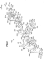
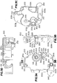
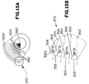
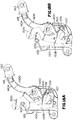
- Ein Seilgreifer, umfassend:ein Gehäuse (200) mit einer Führung für ein längliches Element, die einen Durchgang für ein längliches Element bildet, wobei der Durchgang für ein längliches Element konfiguriert und angeordnet ist, um ein längliches Element aufzunehmen;einen Sperrnocken (300), der schwenkbar mit dem Gehäuse gekoppelt ist, wobei der Sperrnocken konfiguriert und angeordnet ist, um ein längliches Element, das in dem Durchgang für ein längliches Element aufgenommen ist, selektiv in Eingriff zu bringen;ein Nockenvorspannelement (132), das positioniert ist, um eine relativ geringe Vorspannkraft auf den Sperrnocken in Richtung auf ein längliches Element auszuüben, das in dem Durchgang für ein längliches Element aufgenommen ist, wobei der relativ geringen Vorspannkraft während des normalen Betriebs des Seilgreifers durch Schwerkraft entgegengewirkt wird, um zu ermöglichen, dass der Seilgreifer sich auf dem länglichen Element nach oben und unten bewegt, ohne dass der Sperrnocken auf dem länglichen Element beim normalen Betrieb verriegelt wird, während Trägheitskräfte auf dem Sperrnocken und die geringe Vorspannkraft des Nockenvorspannelements bei einem Sturzereignis zusammenwirken, um den Sperrnocken auf das längliche Element zu drehen, um den Sperrnocken auf dem länglichen Element in dem Durchgang für ein längliches Element zu verriegeln; undeinen Sperrarm (400), der schwenkbar mit dem Gehäuse gekoppelt ist, wobei der Sperrarm ein erstes Ende aufweist, das konfiguriert und angeordnet ist, um mit einem Sicherheitsgurtzeug eines Benutzers gekoppelt zu werden, und ein zweites Ende, das konfiguriert und angeordnet ist, um den Sperrnocken selektiv in Eingriff zu bringen, um den Sperrnocken auf dem länglichen Element in dem Durchgang für ein längliches Element bei einem Sturzereignis selektiv zu verriegeln.
- Der Seilgreifer nach Anspruch 1, ferner umfassend:
eine drehende Seitenplatte, die schwenkbar mit dem Gehäuse gekoppelt ist, um selektiv eine Seitenöffnung zu dem Durchgang für ein längliches Element des Gehäuses zu blockieren. - Der Seilgreifer nach Anspruch 2, ferner umfassend:
eine feste Seitenplatte, die mit dem Gehäuse gekoppelt ist, wobei der Sperrnocken, der Sperrarm und die drehende Seitenplatte zwischen der festen Seitenplatte und dem Gehäuse positioniert sind. - Der Seilgreifer nach Anspruch 1, ferner umfassend:
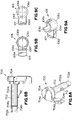
den Sperrnocken mit einer radialen Kante, die konfiguriert und angeordnet ist, um ein längliches Element in Eingriff zu bringen, wobei die radiale Kante eine Krümmung aufweist, die in Bezug auf eine Schwenkverbindung mit dem Gehäuse so variiert, dass die radiale Kante jedes längliche Element in einem Kontaktwinkel in Eingriff bringt, der gleich ist, selbst wenn längliche Elemente unterschiedlicher Durchmesser in dem Durchgang für ein längliches Element des Gehäuses aufgenommen sind. - Der Seilgreifer nach Anspruch 1, ferner umfassend:eine feste Seitenplatte, die mit dem Gehäuse gekoppelt ist, wobei der Sperrnocken, der Sperrarm und die drehende Seitenplatte zwischen der festen Seitenplatte und dem Gehäuse positioniert sind;einen Federabstandshalter, der zwischen dem Sperrarm und der festen Platte angeordnet ist, wobei der Abstandshalter einen Federhalteschlitz aufweist, der in einem Ende des Abstandshalters gebildet ist; undeine Armfeder mit einem ersten Endabschnitt, einem zweiten Endabschnitt und einem gewickelten Abschnitt, der zwischen dem ersten Endabschnitt und dem zweiten Endabschnitt angeordnet ist, wobei der gewickelte Abschnitt um den Federabstandshalter aufgenommen ist, der erste Endabschnitt der Armfeder in dem Federhalteschlitz des Federabstandshalters aufgenommen ist, der erste Endabschnitt der Armfeder ferner in Eingriff mit einem Abschnitt des Gehäuses steht, der zweite Endabschnitt der Armfeder in Eingriff mit dem Sperrarm steht, um eine Vorspannkraft auf den Sperrarm auszuüben.
- Der Seilgreifer nach Anspruch 5, wobei das Gehäuse einen Zapfen mit einem ausgeschnittenen Abschnitt einschließt, wobei der Federabstandshalter einen zentralen Durchgang aufweist, wobei der Zapfen des Gehäuses in dem zentralen Durchgang aufgenommen ist und der erste Endabschnitt der Armfeder in dem ausgeschnittenen Abschnitt des Zapfens aufgenommen ist, um den ersten Endabschnitt der Armfeder mit dem Gehäuse in Eingriff zu bringen.
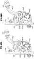
- Der Seilgreifer nach Anspruch 2, ferner umfassend:
mindestens eine Walze, die nahe einem Ende der drehenden Seitenplatte gekoppelt ist, wobei die mindestens eine Walze zum Führen eines länglichen Elements durch den Durchgang für ein längliches Element konfiguriert ist. - Der Seilgreifer nach Anspruch 2, ferner umfassend:
eine Seitenplattenfeder, die zwischen dem Gehäuse und der drehenden Seitenplatte gekoppelt ist, um eine Vorspannkraft auf die drehende Seitenplatte auszuüben. - Der Seilgreifer nach Anspruch 2, ferner umfassend:mindestens einen Hebel;eine Hebelfeder, die zwischen dem Gehäuse und dem mindestens einen Hebel gekoppelt ist, um eine Vorspannkraft auf den mindestens einen Hebel auszuüben;ein Sperrelement, das gekoppelt ist, um sich in Reaktion auf die Drehung des mindestens einen Hebels zu drehen, wobei das Sperrelement konfiguriert und angeordnet ist, um die drehende Seitenplatte selektiv in Eingriff zu bringen, um die drehende Seitenplatte in einer statischen Position in Bezug auf das Gehäuse zu verriegeln, um selektiv mindestens einen Abschnitt der Seitenöffnung des länglichen Durchgangs zu blockieren; undeine Verriegelungsfeder, die zwischen dem Gehäuse und der drehenden Seitenplatte gekoppelt ist, um eine Vorspannkraft auf die drehende Seitenplatte auszuüben.
- Der Seilgreifer nach Anspruch 9, ferner umfassend:
den Hebel, der sich durch einen Schlitz in dem Gehäuse erstreckt. - Der Seilgreifer nach Anspruch 1, wobei der Sperrarm einen energieabsorbierenden Abschnitt einschließt, der konfiguriert und angeordnet ist, um Energie während eines Sturzereignisses zu absorbieren.
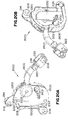
- Ein Seilgreifer nach Anspruch 1, ferner umfassend:
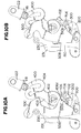
mindestens eine Umgehungshalterung, die konfiguriert und angeordnet ist, um ein längliches Element an eine Tragstruktur zu koppeln. - Der Seilgreifer nach Anspruch 12, wobei die Umgehungshalterung ferner umfasst:eine Basishalterung, die konfiguriert und angeordnet ist, um an die Tragstruktur gekoppelt zu sein;eine Hülsenklemme, die mit der Basishalterung gekoppelt ist, wobei die Hülsenklemme beabstandete, einander gegenüber angeordnete erste und zweite Haltelaschen einschließt; undeine rohrförmige Hülse mit einem zentralen Durchgang und beabstandete erste und zweite, einander gegenüber angeordnete Aussparungen, die in einer äußeren Oberfläche der Hülse gebildet sind, wobei die erste und zweite Haltelasche der Hülsenklemme konfiguriert und angeordnet sind, um die jeweilige erste und zweite einander gegenüber angeordnete Aussparung der rohrförmigen Hülse selektiv aufzunehmen.
- Ein Verfahren zum Betätigen eines Seilgreifers, das Verfahren umfassend:Drehen eines Hebels, der drehbar an ein Gehäuse gekoppelt ist, um eine drehende Seitenplatte mit einer Hand eines Benutzers freizugeben;Zurückziehen an einem Ende der drehenden Seitenplatte, um einen Abschnitt der drehenden Seitenplatte weg von einer Seitenöffnung zu einem Durchgang für ein längliches Element, der in dem Gehäuse gebildet ist, mit der Hand des Benutzers zu schwenken;Positionieren des Seilgreifers, um ein längliches Element in dem Durchgang für ein längliches Element des Gehäuses mit der Hand des Benutzers aufzunehmen; undFreigeben der drehenden Seitenplatte, um zu ermöglichen, dass die drehende Seitenplatte zumindest teilweise die Seitenöffnung zu dem Durchgang für ein längliches Element des Gehäuses abdeckt, um das längliche Element mit dem Durchgang für ein längliches Element zurückzuhalten.
- Das Verfahren nach Anspruch 14, ferner umfassend:Drehen eines Hebels, der drehbar mit einem Gehäuse gekoppelt ist, um eine drehende Seitenplatte mit einer Hand des Benutzers zu lösen;Zurückziehen an einem Ende der drehenden Seitenplatte, um einen Abschnitt der drehenden Seitenplatte weg von einer Seitenöffnung zu einem Durchgang für ein längliches Element, der in dem Gehäuse gebildet ist, mit der Hand des Benutzers zu schwenken;Entfernen des länglichen Elements aus dem Durchgang für ein längliches Element des Gehäuses mit der Hand des Benutzers; undFreigeben der drehenden Seitenplatte, um zu ermöglichen, dass die drehende Seitenplatte zumindest teilweise die Seitenöffnung zu dem Durchgang für ein längliches Element des Gehäuses abdeckt.
Applications Claiming Priority (3)
| Application Number | Priority Date | Filing Date | Title |
|---|---|---|---|
| US13/551,845 US9132297B2 (en) | 2012-07-18 | 2012-07-18 | Rope grab |
| US13/891,871 US9168402B2 (en) | 2012-07-18 | 2013-05-10 | Rope grab |
| PCT/US2013/050868 WO2014015026A2 (en) | 2012-07-18 | 2013-07-17 | Rope grab |
Publications (2)
| Publication Number | Publication Date |
|---|---|
| EP2877251A2 EP2877251A2 (de) | 2015-06-03 |
| EP2877251B1 true EP2877251B1 (de) | 2020-01-22 |
Family
ID=48877575
Family Applications (1)
| Application Number | Title | Priority Date | Filing Date |
|---|---|---|---|
| EP13742361.2A Active EP2877251B1 (de) | 2012-07-18 | 2013-07-17 | Seilgreifer |
Country Status (11)
| Country | Link |
|---|---|
| US (1) | US9168402B2 (de) |
| EP (1) | EP2877251B1 (de) |
| JP (1) | JP6426605B2 (de) |
| CN (1) | CN105263584B (de) |
| AU (1) | AU2013292646B2 (de) |
| BR (1) | BR112015001131B1 (de) |
| CA (1) | CA2877993C (de) |
| MX (1) | MX2015000802A (de) |
| RU (1) | RU2657412C2 (de) |
| SG (1) | SG11201500296WA (de) |
| WO (1) | WO2014015026A2 (de) |
Families Citing this family (37)
| Publication number | Priority date | Publication date | Assignee | Title |
|---|---|---|---|---|
| DE102012207223B3 (de) * | 2012-04-30 | 2013-09-26 | Bornack Gmbh & Co. Kg | Sicherungsvorrichtung |
| US9132297B2 (en) * | 2012-07-18 | 2015-09-15 | D B Industries, Llc | Rope grab |
| US9168402B2 (en) * | 2012-07-18 | 2015-10-27 | D B Industries, Llc | Rope grab |
| US9623269B2 (en) * | 2013-03-14 | 2017-04-18 | Black Diamond Equipment, Ltd. | Systems for assisted braking belay with a cam-clutch mechanism |
| USD764258S1 (en) * | 2013-05-10 | 2016-08-23 | D B Industries, Llc | Housing of a rope grab |
| USD739212S1 (en) | 2013-05-10 | 2015-09-22 | D B Industries, Llc | Housing of a rope grab |
| USD746125S1 (en) * | 2013-05-10 | 2015-12-29 | D B Industries, Llc | Fixed side plate of a rope grab |
| FR3011475B1 (fr) * | 2013-10-07 | 2016-03-04 | Simond Ets | Descendeur-assureur autobloquant |
| CA2887034A1 (en) * | 2014-04-01 | 2015-10-01 | Buckingham Manufacturing Company, Inc. | Ladder fall protection system and fall arrester |
| EP3148653B1 (de) * | 2014-05-29 | 2020-10-21 | Honeywell International Inc. | Geführter fallstopper mit kraftbegrenzer |
| EP2982417B1 (de) * | 2014-08-04 | 2018-07-04 | Honeywell International Inc. | Verformbarer Energieabsorber mit Verformungsindikator |
| US11660475B2 (en) | 2015-04-07 | 2023-05-30 | Harken, Incorporated | High load descender with adaptive release linkage |
| US10583315B2 (en) * | 2015-04-07 | 2020-03-10 | Harken, Incorporated | High load descender with adaptive release linkage |
| US10099087B2 (en) * | 2015-04-24 | 2018-10-16 | Buckingham Manufacturing Company, Inc. | Cam assembly for use with pole climbing fall restriction device |
| US9604079B2 (en) | 2015-07-21 | 2017-03-28 | Merritt Arboreal Design, Inc. | On-rope work positioning device |
| WO2017030558A1 (en) * | 2015-08-18 | 2017-02-23 | Honeywell International Inc. | Shuttle for a climbing protection system |
| US9750959B2 (en) * | 2015-10-21 | 2017-09-05 | Msa Technology, Llc | Cable grab device |
| EP3402577A1 (de) | 2016-01-15 | 2018-11-21 | DALEKOVOD PROIZVODNJA d.o.o. | Absturzsicherung mit torsionsenergieabsorptionsmitteln |
| US10953247B2 (en) * | 2016-03-23 | 2021-03-23 | Honeywell International Inc. | Shuttle for a climbing protection system |
| PT3472017T (pt) * | 2016-06-17 | 2022-05-04 | Buttercup Business Inc | Sistema de travessia de segurança de via binária de segunda geração |
| CN106139449A (zh) * | 2016-08-23 | 2016-11-23 | 国网浙江杭州市余杭区供电公司 | 安全器 |
| US10035028B1 (en) * | 2017-01-04 | 2018-07-31 | Mallory Safety+Supply | Emergency descender device |
| US20200016439A1 (en) * | 2017-03-31 | 2020-01-16 | 3M Innovative Properties Company | Fall protection equipment connection status and control |
| EP3606621B1 (de) * | 2017-04-03 | 2022-03-02 | 3M Innovative Properties Company | Fallschutzvorrichtung mit schutzhülle und hülsenanordnung |
| US20190338593A1 (en) * | 2017-07-17 | 2019-11-07 | Safeworks, Llc | Integrated climb assist and fall arrest systems and methods |
| WO2019126135A1 (en) * | 2017-12-19 | 2019-06-27 | 3M Innovative Properties Company | Top bracket for fall protection safety system |
| USD889691S1 (en) | 2017-12-22 | 2020-07-07 | Werner Co. | Strand grab |
| US10316585B1 (en) | 2017-12-22 | 2019-06-11 | Werner Co. | Strand grab and ladder including the same |
| DE102018102325B4 (de) * | 2018-02-01 | 2021-01-21 | Bornack Gmbh & Co. Kg | Sicherungsvorrichtung |
| CN109529218B (zh) * | 2018-12-27 | 2023-11-21 | 济南奔速超伦机械设备有限公司 | 一种抓绳器 |
| CN111437537B (zh) * | 2019-09-20 | 2024-04-26 | 中际联合(北京)科技股份有限公司 | 防坠落装置和防坠落系统 |
| EP3835619A1 (de) * | 2019-12-11 | 2021-06-16 | BAUERandMORE GmbH | Bremsscheibe für eine seilbremse zum seilklettern, seilbremse zum seilklettern, und verfahren zum nachrüsten einer seilbremse |
| US11406851B2 (en) * | 2020-01-17 | 2022-08-09 | Honeywell International Inc. | Fall protection locking system |
| US11642554B2 (en) * | 2020-03-26 | 2023-05-09 | Honeywell International Inc. | Shock absorber for fall protection locking system |
| WO2021226612A1 (en) | 2020-05-06 | 2021-11-11 | Exxonmobil Upstream Research Company | Geological reasoning with graph networks for hydrocarbon identification |
| US11781610B2 (en) * | 2021-06-18 | 2023-10-10 | Cmc Rescue, Inc. | Systems for line device |
| US20230405365A1 (en) * | 2022-06-17 | 2023-12-21 | Werner Co. | Cable grab |
Family Cites Families (66)
| Publication number | Priority date | Publication date | Assignee | Title |
|---|---|---|---|---|
| US2561514A (en) * | 1949-04-12 | 1951-07-24 | Isaac D Houseman | Strand brake |
| US2606350A (en) | 1949-07-05 | 1952-08-12 | French Humboldt | Cable strain clamp |
| US3177543A (en) | 1962-11-14 | 1965-04-13 | Cecil D Fountain | Safety locking device |
| US3179994A (en) | 1964-01-22 | 1965-04-27 | Meyer Machine Inc | Safety appliance |
| US3811155A (en) * | 1972-06-21 | 1974-05-21 | L Stafford | Rope grab assembly |
| JPS5314074Y2 (de) * | 1972-08-30 | 1978-04-14 | ||
| US3852943A (en) * | 1973-08-27 | 1974-12-10 | Meyer Ind Inc | Portable safety clamp |
| US4071926A (en) | 1974-05-09 | 1978-02-07 | D. B. Enterprises, Inc. | Safety device for ladder climbers |
| US3876036A (en) | 1974-06-20 | 1975-04-08 | Db Enterprises | Rope grab safety device |
| GB1536354A (en) | 1976-07-08 | 1978-12-20 | Britax Ltd | Energy absorber |
| US4059871A (en) * | 1976-09-17 | 1977-11-29 | Swager William E | Clamping device with locking trigger arm |
| US4077094A (en) * | 1976-09-17 | 1978-03-07 | Swager William E | Clamping device for a rope, cable, annular bar, or the like |
| DE2810928A1 (de) | 1978-03-14 | 1979-09-27 | Moser Kurt | Absturzsicherung |
| DE2812073C3 (de) | 1978-03-20 | 1981-01-08 | Mittelmann & Co Armaturenwerk, 5603 Wuelfrath | Seilsicherungsklemme |
| JPS55158751U (de) * | 1979-04-28 | 1980-11-14 | ||
| CH659299B (de) | 1983-01-17 | 1987-01-15 | ||
| US4542884A (en) | 1983-06-06 | 1985-09-24 | Dodge Jr Cleveland E | Removable double action rope grip |
| US4521000A (en) * | 1983-06-06 | 1985-06-04 | Dodge Jr Cleveland E | Bypassing double action rope grip |
| DE3426551A1 (de) | 1983-11-23 | 1985-05-30 | Virtaradat Oy, Helsinki | Daempfungseinrichtung |
| DE3425947A1 (de) | 1984-07-13 | 1986-01-16 | Söll KG Industrieschmiede, 8670 Hof | Schlitten fuer eine steigschutzvorrichtung zum besteigen einer leiter |
| US4560029A (en) * | 1984-08-29 | 1985-12-24 | Wgm Safety Corp. | Security device |
| US4657110A (en) * | 1984-12-10 | 1987-04-14 | D B Industries, Inc. | Inertia rope grab |
| DE3531391A1 (de) | 1985-09-03 | 1987-03-12 | Bornack Herbert Fa | Fallbremse |
| DE8606240U1 (de) | 1986-03-07 | 1986-04-24 | Lorenz Hasenbach GmbH & Co KG, 6277 Bad Camberg | Fallschutzläufer für Fallschutzschienen |
| GB8627320D0 (en) * | 1986-11-14 | 1986-12-17 | Latchways Ltd | Lockable load-transfer |
| US4791243A (en) | 1987-02-04 | 1988-12-13 | Anco Engineers, Inc. | Compact device for long stroke energy absorption |
| GB9011370D0 (en) | 1990-05-22 | 1990-07-11 | Barrow Hepburn Sala Ltd | Energy-absorbing bracket |
| US5156240A (en) * | 1991-05-31 | 1992-10-20 | Meyer Ostrobrod | Rope grab |
| US5146655A (en) * | 1991-10-29 | 1992-09-15 | Gibbs Peter E | Safety clamp appliance |
| US5265696A (en) * | 1992-01-31 | 1993-11-30 | D B Industries, Inc. | Ladder climbing safety clamp |
| FR2720283B1 (fr) * | 1994-04-21 | 1996-08-23 | Froment Sa | Appareil anti-chute verrouillage automatiquement sur une corde de sécurité. |
| GB2293193A (en) * | 1994-09-19 | 1996-03-20 | Latchways Ltd | Fall arrest device |
| DE29501716U1 (de) | 1995-02-03 | 1995-03-16 | Soell Gmbh | Fangeinrichtung für ein Steigschutzsystem |
| FR2736273A1 (fr) * | 1995-07-03 | 1997-01-10 | Sk Sarl | Antichute mobile pour support d'assurage |
| FR2751233B1 (fr) * | 1996-07-16 | 1998-10-09 | Tractel Sa | Dispositif d'arret automatique de chute pour des personnels travaillant en hauteur |
| DE29805788U1 (de) * | 1998-03-30 | 1998-07-30 | Soell Gmbh | Fangeinrichtung für ein Steigschutzsystem |
| FR2780656B1 (fr) * | 1998-07-03 | 2001-08-03 | Dalloz Fall Prot | Appareil anti-chute sur cable vertical |
| EP1338304B1 (de) | 1998-10-23 | 2004-09-15 | D B Industries, Inc. | Energieabsorbierender Verbinder |
| DE29906047U1 (de) | 1999-04-01 | 1999-07-01 | Soell Gmbh | Auffanggerät |
| DE29920850U1 (de) | 1999-11-29 | 2000-02-24 | Soell Gmbh | Fangeinrichtung für ein Steigschutzsystem |
| ATE356946T1 (de) | 1999-12-21 | 2007-04-15 | Keyguard Ltd | Energie absorber |
| FR2804708B1 (fr) | 2000-02-03 | 2002-03-15 | Dalloz Fall Prot | Dispositif de fixation d'une ligne de vie contre une paroi |
| US20020014370A1 (en) * | 2000-04-17 | 2002-02-07 | Casebolt Scott C. | Fall arrest methods and apparatus with u-joint connector |
| US6648101B2 (en) | 2001-05-24 | 2003-11-18 | Michael P. Kurtgis | Fall protection lanyard apparatus |
| DE20217045U1 (de) | 2002-11-05 | 2003-04-10 | Christian Dalloz Holding Deuts | Zusammenfaltbare Leiter mit einem Steigschutzsystem |
| GB2396195B (en) | 2002-12-03 | 2005-11-30 | Simon Louis Rood | Support post for a safety line |
| FR2857601B1 (fr) | 2003-07-17 | 2005-11-18 | Rodolphe Argoud | Dispositif amortisseur de choc pour l'ancrage d'une ligne de vie ou similaire |
| DE20314230U1 (de) * | 2003-09-12 | 2003-11-06 | Christian Dalloz Holding Deuts | Auffanggerät als Teil einer Absturzsicherung für Leitern und ähnliche Steigwege |
| ES2389481T3 (es) * | 2003-10-21 | 2012-10-26 | Uniline Safety Systems Limited | Dispositivo anticaídas y sistema que incorpora el mismo |
| GB0328937D0 (en) | 2003-12-13 | 2004-01-14 | Checkmate Uk Ltd | Lifeline trolley |
| GB0426149D0 (en) | 2004-11-29 | 2004-12-29 | Rapid Rail Internat | Fall arrest |
| GB0510653D0 (en) | 2005-05-25 | 2005-06-29 | Rapid Rail Internat Ltd | Shock absorber |
| DE202005011338U1 (de) | 2005-07-15 | 2006-11-23 | Christian Dalloz Holding Deutschland Gmbh & Co. Kg | Auffanggerät für ein Steigschutzsystem |
| ATE491097T1 (de) * | 2005-09-20 | 2010-12-15 | Db Ind Inc | Karabinerhaken mit doppelverriegelung |
| EP2091614A1 (de) * | 2006-10-16 | 2009-08-26 | SPERIAN FALL PROTECTION Deutschland GmbH & Co. KG | Auffanggerät für ein steigschutzsystem |
| DE202007012804U1 (de) | 2007-09-13 | 2009-02-12 | Sperian Fall Protection Deutschland Gmbh & Co. Kg | Steigschutzsystem |
| WO2009100315A2 (en) | 2008-02-06 | 2009-08-13 | Sperian Fall Protection, Inc. | Energy absorbers, connectors and horizontal lifeline systems |
| US9272168B2 (en) | 2008-02-06 | 2016-03-01 | Honeywell International Inc. | Energy absorbers, connectors and horizontal lifeline systems |
| GB0816343D0 (en) * | 2008-09-06 | 2008-10-15 | Uniline Safety Systems Ltd | Fall arrest device |
| FR2938771B1 (fr) * | 2008-11-27 | 2010-12-31 | Zedel | Dispositif bloqueur a came pour l'assurage sur corde fixe |
| CN201412476Y (zh) * | 2009-04-02 | 2010-02-24 | 青岛武晓集团有限公司 | 一种新型抓绳器 |
| US8720014B2 (en) * | 2009-06-02 | 2014-05-13 | Yasuharu Nagaki | Trigger grip |
| AU2010308521B2 (en) * | 2009-10-23 | 2014-03-06 | D B Industries, Llc | Energy absorber |
| FR2962658B1 (fr) | 2010-07-16 | 2012-07-13 | Tractel Sas | Systeme de ligne de vie pour protection antichute, coulisseau, support de cable et manchon |
| US8733739B2 (en) * | 2011-03-21 | 2014-05-27 | Kirk Martin Mauthner | Device that integrates an ascender with a pulley block |
| US9168402B2 (en) * | 2012-07-18 | 2015-10-27 | D B Industries, Llc | Rope grab |
-
2013
- 2013-05-10 US US13/891,871 patent/US9168402B2/en active Active
- 2013-07-17 MX MX2015000802A patent/MX2015000802A/es unknown
- 2013-07-17 WO PCT/US2013/050868 patent/WO2014015026A2/en active Search and Examination
- 2013-07-17 BR BR112015001131-4A patent/BR112015001131B1/pt active IP Right Grant
- 2013-07-17 RU RU2014153262A patent/RU2657412C2/ru active
- 2013-07-17 EP EP13742361.2A patent/EP2877251B1/de active Active
- 2013-07-17 SG SG11201500296WA patent/SG11201500296WA/en unknown
- 2013-07-17 AU AU2013292646A patent/AU2013292646B2/en active Active
- 2013-07-17 JP JP2015523221A patent/JP6426605B2/ja not_active Expired - Fee Related
- 2013-07-17 CA CA2877993A patent/CA2877993C/en active Active
- 2013-07-17 CN CN201380037916.8A patent/CN105263584B/zh active Active
Non-Patent Citations (1)
| Title |
|---|
| None * |
Also Published As
| Publication number | Publication date |
|---|---|
| WO2014015026A2 (en) | 2014-01-23 |
| CN105263584B (zh) | 2019-04-02 |
| RU2657412C2 (ru) | 2018-06-13 |
| EP2877251A2 (de) | 2015-06-03 |
| JP2015531617A (ja) | 2015-11-05 |
| SG11201500296WA (en) | 2015-02-27 |
| CN105263584A (zh) | 2016-01-20 |
| WO2014015026A3 (en) | 2014-09-12 |
| US20140020988A1 (en) | 2014-01-23 |
| CA2877993C (en) | 2020-08-25 |
| AU2013292646B2 (en) | 2017-07-06 |
| JP6426605B2 (ja) | 2018-11-21 |
| BR112015001131B1 (pt) | 2021-03-23 |
| RU2014153262A (ru) | 2016-09-10 |
| AU2013292646A1 (en) | 2015-01-22 |
| MX2015000802A (es) | 2015-05-08 |
| US9168402B2 (en) | 2015-10-27 |
| CA2877993A1 (en) | 2014-01-23 |
| BR112015001131A2 (pt) | 2017-06-27 |
Similar Documents
| Publication | Publication Date | Title |
|---|---|---|
| EP2877251B1 (de) | Seilgreifer | |
| US9636528B2 (en) | Rope grab | |
| EP2506937B1 (de) | Selbsteinziehende rettungsleine mit ablösbarer rettungsleine | |
| US20170274230A1 (en) | Snap hook | |
| EP3307399B1 (de) | D-ringhalteranordnung | |
| EP2796172B1 (de) | Absturzsicherungsvorrichtung | |
| US6899203B1 (en) | Rope management apparatus | |
| EP3337987B1 (de) | Karabinerunterteiler und fallschutzsystem | |
| EP1666104A1 (de) | Vorrichtung zum anhängen und arretieren von kletterseilen | |
| EP1596941B1 (de) | Sicherheitsvorrichtung | |
| US20100294590A1 (en) | Method, Apparatus, and Arrangement for a Lifeline System | |
| CA3069385A1 (en) | Fall arresting device connector | |
| US20170050055A1 (en) | Auto-Blocking Rappelling and Belaying Device | |
| EP3001047B1 (de) | Karabiner | |
| GB2441140A (en) | Rope grab | |
| US9149667B2 (en) | Safety device | |
| MX2008008436A (en) | Slidable beam anchor |
Legal Events
| Date | Code | Title | Description |
|---|---|---|---|
| PUAI | Public reference made under article 153(3) epc to a published international application that has entered the european phase |
Free format text: ORIGINAL CODE: 0009012 |
|
| 17P | Request for examination filed |
Effective date: 20150116 |
|
| AK | Designated contracting states |
Kind code of ref document: A2 Designated state(s): AL AT BE BG CH CY CZ DE DK EE ES FI FR GB GR HR HU IE IS IT LI LT LU LV MC MK MT NL NO PL PT RO RS SE SI SK SM TR |
|
| AX | Request for extension of the european patent |
Extension state: BA ME |
|
| DAX | Request for extension of the european patent (deleted) | ||
| GRAP | Despatch of communication of intention to grant a patent |
Free format text: ORIGINAL CODE: EPIDOSNIGR1 |
|
| STAA | Information on the status of an ep patent application or granted ep patent |
Free format text: STATUS: GRANT OF PATENT IS INTENDED |
|
| INTG | Intention to grant announced |
Effective date: 20190816 |
|
| GRAS | Grant fee paid |
Free format text: ORIGINAL CODE: EPIDOSNIGR3 |
|
| GRAA | (expected) grant |
Free format text: ORIGINAL CODE: 0009210 |
|
| STAA | Information on the status of an ep patent application or granted ep patent |
Free format text: STATUS: THE PATENT HAS BEEN GRANTED |
|
| AK | Designated contracting states |
Kind code of ref document: B1 Designated state(s): AL AT BE BG CH CY CZ DE DK EE ES FI FR GB GR HR HU IE IS IT LI LT LU LV MC MK MT NL NO PL PT RO RS SE SI SK SM TR |
|
| REG | Reference to a national code |
Ref country code: GB Ref legal event code: FG4D |
|
| REG | Reference to a national code |
Ref country code: CH Ref legal event code: EP |
|
| REG | Reference to a national code |
Ref country code: AT Ref legal event code: REF Ref document number: 1226540 Country of ref document: AT Kind code of ref document: T Effective date: 20200215 |
|
| REG | Reference to a national code |
Ref country code: IE Ref legal event code: FG4D |
|
| REG | Reference to a national code |
Ref country code: DE Ref legal event code: R096 Ref document number: 602013065295 Country of ref document: DE |
|
| REG | Reference to a national code |
Ref country code: NL Ref legal event code: MP Effective date: 20200122 |
|
| REG | Reference to a national code |
Ref country code: LT Ref legal event code: MG4D |
|
| PG25 | Lapsed in a contracting state [announced via postgrant information from national office to epo] |
Ref country code: PT Free format text: LAPSE BECAUSE OF FAILURE TO SUBMIT A TRANSLATION OF THE DESCRIPTION OR TO PAY THE FEE WITHIN THE PRESCRIBED TIME-LIMIT Effective date: 20200614 Ref country code: FI Free format text: LAPSE BECAUSE OF FAILURE TO SUBMIT A TRANSLATION OF THE DESCRIPTION OR TO PAY THE FEE WITHIN THE PRESCRIBED TIME-LIMIT Effective date: 20200122 Ref country code: NL Free format text: LAPSE BECAUSE OF FAILURE TO SUBMIT A TRANSLATION OF THE DESCRIPTION OR TO PAY THE FEE WITHIN THE PRESCRIBED TIME-LIMIT Effective date: 20200122 Ref country code: RS Free format text: LAPSE BECAUSE OF FAILURE TO SUBMIT A TRANSLATION OF THE DESCRIPTION OR TO PAY THE FEE WITHIN THE PRESCRIBED TIME-LIMIT Effective date: 20200122 Ref country code: NO Free format text: LAPSE BECAUSE OF FAILURE TO SUBMIT A TRANSLATION OF THE DESCRIPTION OR TO PAY THE FEE WITHIN THE PRESCRIBED TIME-LIMIT Effective date: 20200422 |
|
| PG25 | Lapsed in a contracting state [announced via postgrant information from national office to epo] |
Ref country code: BG Free format text: LAPSE BECAUSE OF FAILURE TO SUBMIT A TRANSLATION OF THE DESCRIPTION OR TO PAY THE FEE WITHIN THE PRESCRIBED TIME-LIMIT Effective date: 20200422 Ref country code: SE Free format text: LAPSE BECAUSE OF FAILURE TO SUBMIT A TRANSLATION OF THE DESCRIPTION OR TO PAY THE FEE WITHIN THE PRESCRIBED TIME-LIMIT Effective date: 20200122 Ref country code: LV Free format text: LAPSE BECAUSE OF FAILURE TO SUBMIT A TRANSLATION OF THE DESCRIPTION OR TO PAY THE FEE WITHIN THE PRESCRIBED TIME-LIMIT Effective date: 20200122 Ref country code: HR Free format text: LAPSE BECAUSE OF FAILURE TO SUBMIT A TRANSLATION OF THE DESCRIPTION OR TO PAY THE FEE WITHIN THE PRESCRIBED TIME-LIMIT Effective date: 20200122 Ref country code: GR Free format text: LAPSE BECAUSE OF FAILURE TO SUBMIT A TRANSLATION OF THE DESCRIPTION OR TO PAY THE FEE WITHIN THE PRESCRIBED TIME-LIMIT Effective date: 20200423 Ref country code: IS Free format text: LAPSE BECAUSE OF FAILURE TO SUBMIT A TRANSLATION OF THE DESCRIPTION OR TO PAY THE FEE WITHIN THE PRESCRIBED TIME-LIMIT Effective date: 20200522 |
|
| REG | Reference to a national code |
Ref country code: DE Ref legal event code: R097 Ref document number: 602013065295 Country of ref document: DE |
|
| PG25 | Lapsed in a contracting state [announced via postgrant information from national office to epo] |
Ref country code: SM Free format text: LAPSE BECAUSE OF FAILURE TO SUBMIT A TRANSLATION OF THE DESCRIPTION OR TO PAY THE FEE WITHIN THE PRESCRIBED TIME-LIMIT Effective date: 20200122 Ref country code: SK Free format text: LAPSE BECAUSE OF FAILURE TO SUBMIT A TRANSLATION OF THE DESCRIPTION OR TO PAY THE FEE WITHIN THE PRESCRIBED TIME-LIMIT Effective date: 20200122 Ref country code: RO Free format text: LAPSE BECAUSE OF FAILURE TO SUBMIT A TRANSLATION OF THE DESCRIPTION OR TO PAY THE FEE WITHIN THE PRESCRIBED TIME-LIMIT Effective date: 20200122 Ref country code: ES Free format text: LAPSE BECAUSE OF FAILURE TO SUBMIT A TRANSLATION OF THE DESCRIPTION OR TO PAY THE FEE WITHIN THE PRESCRIBED TIME-LIMIT Effective date: 20200122 Ref country code: CZ Free format text: LAPSE BECAUSE OF FAILURE TO SUBMIT A TRANSLATION OF THE DESCRIPTION OR TO PAY THE FEE WITHIN THE PRESCRIBED TIME-LIMIT Effective date: 20200122 Ref country code: LT Free format text: LAPSE BECAUSE OF FAILURE TO SUBMIT A TRANSLATION OF THE DESCRIPTION OR TO PAY THE FEE WITHIN THE PRESCRIBED TIME-LIMIT Effective date: 20200122 Ref country code: EE Free format text: LAPSE BECAUSE OF FAILURE TO SUBMIT A TRANSLATION OF THE DESCRIPTION OR TO PAY THE FEE WITHIN THE PRESCRIBED TIME-LIMIT Effective date: 20200122 Ref country code: DK Free format text: LAPSE BECAUSE OF FAILURE TO SUBMIT A TRANSLATION OF THE DESCRIPTION OR TO PAY THE FEE WITHIN THE PRESCRIBED TIME-LIMIT Effective date: 20200122 |
|
| REG | Reference to a national code |
Ref country code: AT Ref legal event code: MK05 Ref document number: 1226540 Country of ref document: AT Kind code of ref document: T Effective date: 20200122 |
|
| PLBE | No opposition filed within time limit |
Free format text: ORIGINAL CODE: 0009261 |
|
| STAA | Information on the status of an ep patent application or granted ep patent |
Free format text: STATUS: NO OPPOSITION FILED WITHIN TIME LIMIT |
|
| 26N | No opposition filed |
Effective date: 20201023 |
|
| PG25 | Lapsed in a contracting state [announced via postgrant information from national office to epo] |
Ref country code: AT Free format text: LAPSE BECAUSE OF FAILURE TO SUBMIT A TRANSLATION OF THE DESCRIPTION OR TO PAY THE FEE WITHIN THE PRESCRIBED TIME-LIMIT Effective date: 20200122 Ref country code: IT Free format text: LAPSE BECAUSE OF FAILURE TO SUBMIT A TRANSLATION OF THE DESCRIPTION OR TO PAY THE FEE WITHIN THE PRESCRIBED TIME-LIMIT Effective date: 20200122 |
|
| PG25 | Lapsed in a contracting state [announced via postgrant information from national office to epo] |
Ref country code: PL Free format text: LAPSE BECAUSE OF FAILURE TO SUBMIT A TRANSLATION OF THE DESCRIPTION OR TO PAY THE FEE WITHIN THE PRESCRIBED TIME-LIMIT Effective date: 20200122 Ref country code: SI Free format text: LAPSE BECAUSE OF FAILURE TO SUBMIT A TRANSLATION OF THE DESCRIPTION OR TO PAY THE FEE WITHIN THE PRESCRIBED TIME-LIMIT Effective date: 20200122 Ref country code: MC Free format text: LAPSE BECAUSE OF FAILURE TO SUBMIT A TRANSLATION OF THE DESCRIPTION OR TO PAY THE FEE WITHIN THE PRESCRIBED TIME-LIMIT Effective date: 20200122 |
|
| REG | Reference to a national code |
Ref country code: CH Ref legal event code: PL |
|
| GBPC | Gb: european patent ceased through non-payment of renewal fee |
Effective date: 20200717 |
|
| REG | Reference to a national code |
Ref country code: BE Ref legal event code: MM Effective date: 20200731 |
|
| PG25 | Lapsed in a contracting state [announced via postgrant information from national office to epo] |
Ref country code: CH Free format text: LAPSE BECAUSE OF NON-PAYMENT OF DUE FEES Effective date: 20200731 Ref country code: LI Free format text: LAPSE BECAUSE OF NON-PAYMENT OF DUE FEES Effective date: 20200731 Ref country code: GB Free format text: LAPSE BECAUSE OF NON-PAYMENT OF DUE FEES Effective date: 20200717 Ref country code: FR Free format text: LAPSE BECAUSE OF NON-PAYMENT OF DUE FEES Effective date: 20200731 Ref country code: LU Free format text: LAPSE BECAUSE OF NON-PAYMENT OF DUE FEES Effective date: 20200717 |
|
| PG25 | Lapsed in a contracting state [announced via postgrant information from national office to epo] |
Ref country code: BE Free format text: LAPSE BECAUSE OF NON-PAYMENT OF DUE FEES Effective date: 20200731 |
|
| PG25 | Lapsed in a contracting state [announced via postgrant information from national office to epo] |
Ref country code: IE Free format text: LAPSE BECAUSE OF NON-PAYMENT OF DUE FEES Effective date: 20200717 |
|
| PG25 | Lapsed in a contracting state [announced via postgrant information from national office to epo] |
Ref country code: TR Free format text: LAPSE BECAUSE OF FAILURE TO SUBMIT A TRANSLATION OF THE DESCRIPTION OR TO PAY THE FEE WITHIN THE PRESCRIBED TIME-LIMIT Effective date: 20200122 Ref country code: MT Free format text: LAPSE BECAUSE OF FAILURE TO SUBMIT A TRANSLATION OF THE DESCRIPTION OR TO PAY THE FEE WITHIN THE PRESCRIBED TIME-LIMIT Effective date: 20200122 Ref country code: CY Free format text: LAPSE BECAUSE OF FAILURE TO SUBMIT A TRANSLATION OF THE DESCRIPTION OR TO PAY THE FEE WITHIN THE PRESCRIBED TIME-LIMIT Effective date: 20200122 |
|
| PG25 | Lapsed in a contracting state [announced via postgrant information from national office to epo] |
Ref country code: MK Free format text: LAPSE BECAUSE OF FAILURE TO SUBMIT A TRANSLATION OF THE DESCRIPTION OR TO PAY THE FEE WITHIN THE PRESCRIBED TIME-LIMIT Effective date: 20200122 Ref country code: AL Free format text: LAPSE BECAUSE OF FAILURE TO SUBMIT A TRANSLATION OF THE DESCRIPTION OR TO PAY THE FEE WITHIN THE PRESCRIBED TIME-LIMIT Effective date: 20200122 |
|
| P01 | Opt-out of the competence of the unified patent court (upc) registered |
Effective date: 20230530 |
|
| PGFP | Annual fee paid to national office [announced via postgrant information from national office to epo] |
Ref country code: DE Payment date: 20230620 Year of fee payment: 11 |