EP2876990A1 - Work system and work machines for substrates - Google Patents
Work system and work machines for substrates Download PDFInfo
- Publication number
- EP2876990A1 EP2876990A1 EP12881317.7A EP12881317A EP2876990A1 EP 2876990 A1 EP2876990 A1 EP 2876990A1 EP 12881317 A EP12881317 A EP 12881317A EP 2876990 A1 EP2876990 A1 EP 2876990A1
- Authority
- EP
- European Patent Office
- Prior art keywords
- substrate
- machine
- working machine
- work
- conveyance
- Prior art date
- Legal status (The legal status is an assumption and is not a legal conclusion. Google has not performed a legal analysis and makes no representation as to the accuracy of the status listed.)
- Granted
Links
Images




Classifications
-
- B—PERFORMING OPERATIONS; TRANSPORTING
- B65—CONVEYING; PACKING; STORING; HANDLING THIN OR FILAMENTARY MATERIAL
- B65G—TRANSPORT OR STORAGE DEVICES, e.g. CONVEYORS FOR LOADING OR TIPPING, SHOP CONVEYOR SYSTEMS OR PNEUMATIC TUBE CONVEYORS
- B65G43/00—Control devices, e.g. for safety, warning or fault-correcting
- B65G43/10—Sequence control of conveyors operating in combination
-
- H—ELECTRICITY
- H05—ELECTRIC TECHNIQUES NOT OTHERWISE PROVIDED FOR
- H05K—PRINTED CIRCUITS; CASINGS OR CONSTRUCTIONAL DETAILS OF ELECTRIC APPARATUS; MANUFACTURE OF ASSEMBLAGES OF ELECTRICAL COMPONENTS
- H05K13/00—Apparatus or processes specially adapted for manufacturing or adjusting assemblages of electric components
- H05K13/08—Monitoring manufacture of assemblages
- H05K13/085—Production planning, e.g. of allocation of products to machines, of mounting sequences at machine or facility level
-
- B—PERFORMING OPERATIONS; TRANSPORTING
- B65—CONVEYING; PACKING; STORING; HANDLING THIN OR FILAMENTARY MATERIAL
- B65G—TRANSPORT OR STORAGE DEVICES, e.g. CONVEYORS FOR LOADING OR TIPPING, SHOP CONVEYOR SYSTEMS OR PNEUMATIC TUBE CONVEYORS
- B65G37/00—Combinations of mechanical conveyors of the same kind, or of different kinds, of interest apart from their application in particular machines or use in particular manufacturing processes
-
- B—PERFORMING OPERATIONS; TRANSPORTING
- B65—CONVEYING; PACKING; STORING; HANDLING THIN OR FILAMENTARY MATERIAL
- B65G—TRANSPORT OR STORAGE DEVICES, e.g. CONVEYORS FOR LOADING OR TIPPING, SHOP CONVEYOR SYSTEMS OR PNEUMATIC TUBE CONVEYORS
- B65G43/00—Control devices, e.g. for safety, warning or fault-correcting
-
- B—PERFORMING OPERATIONS; TRANSPORTING
- B65—CONVEYING; PACKING; STORING; HANDLING THIN OR FILAMENTARY MATERIAL
- B65G—TRANSPORT OR STORAGE DEVICES, e.g. CONVEYORS FOR LOADING OR TIPPING, SHOP CONVEYOR SYSTEMS OR PNEUMATIC TUBE CONVEYORS
- B65G43/00—Control devices, e.g. for safety, warning or fault-correcting
- B65G43/08—Control devices operated by article or material being fed, conveyed or discharged
-
- H—ELECTRICITY
- H05—ELECTRIC TECHNIQUES NOT OTHERWISE PROVIDED FOR
- H05K—PRINTED CIRCUITS; CASINGS OR CONSTRUCTIONAL DETAILS OF ELECTRIC APPARATUS; MANUFACTURE OF ASSEMBLAGES OF ELECTRICAL COMPONENTS
- H05K13/00—Apparatus or processes specially adapted for manufacturing or adjusting assemblages of electric components
- H05K13/08—Monitoring manufacture of assemblages
- H05K13/081—Integration of optical monitoring devices in assembly lines; Processes using optical monitoring devices specially adapted for controlling devices or machines in assembly lines
- H05K13/0817—Monitoring of soldering processes
-
- B—PERFORMING OPERATIONS; TRANSPORTING
- B65—CONVEYING; PACKING; STORING; HANDLING THIN OR FILAMENTARY MATERIAL
- B65G—TRANSPORT OR STORAGE DEVICES, e.g. CONVEYORS FOR LOADING OR TIPPING, SHOP CONVEYOR SYSTEMS OR PNEUMATIC TUBE CONVEYORS
- B65G2811/00—Indexing codes relating to common features for more than one conveyor kind or type
- B65G2811/06—Devices controlling the relative position of articles
- B65G2811/0673—Control of conveying operations
-
- H—ELECTRICITY
- H05—ELECTRIC TECHNIQUES NOT OTHERWISE PROVIDED FOR
- H05K—PRINTED CIRCUITS; CASINGS OR CONSTRUCTIONAL DETAILS OF ELECTRIC APPARATUS; MANUFACTURE OF ASSEMBLAGES OF ELECTRICAL COMPONENTS
- H05K13/00—Apparatus or processes specially adapted for manufacturing or adjusting assemblages of electric components
- H05K13/0061—Tools for holding the circuit boards during processing; handling transport of printed circuit boards
Definitions
- the present invention relates to a work system for substrates in which a circuit substrate is conveyed from a working machine disposed upstream out of plural working machines to a working machine disposed downstream and a working machine constituting the work system.
- a work system for substrates includes plural working machines arranged in a line.
- a circuit substrate is conveyed from a working machine disposed upstream out of the plural working machines to a working machine disposed downstream.
- the plural working machines include a working machine that performs coating work such as paste soldering on a circuit substrate, a working machine that performs mounting work of electronic components on a circuit substrate, and an inspection machine that inspects the work results of a variety of work.
- the inspection result of a circuit substrate inspected by the inspection machine is good, that is, when the circuit substrate inspected by the inspection machine is a normal circuit substrate (hereinafter, also referred to as "OK substrate")
- the OK substrate is conveyed downstream through a predetermined path.
- the inspection result of the circuit substrate inspected by the inspection machine is not good, that is, when the circuit substrate inspected by the inspection machine is an abnormal circuit substrate (hereinafter, also referred to as "NG substrate"), the NG substrate moves to a retracted position retracting from the predetermined path.
- NG substrate abnormal circuit substrate
- the present invention is made in consideration of the aforementioned circumstances and an object thereof is to provide a work system for substrates and a working machine with high work efficiency.
- a work system for substrates including: a plurality of working machines that includes a pair of substrate conveyance devices for conveying circuit substrates through two paths and that is arranged in a line; and a control device that controls operations of the pair of substrate conveyance devices of each of the plurality of working machines, in which the circuit substrates are conveyed through the two paths from the working machine disposed upstream out of the plurality of working machines to the working machine disposed downstream, wherein the control device includes a substrate conveyance control unit that controls the operations of the pair of substrate conveyance devices of the upstream working machine and the downstream working machine so that a circuit substrate of which the work result is not good is conveyed to the downstream working machine earlier than a circuit substrate of which the work result is good in a state in which the circuit substrate of which the work result is good and the circuit substrate of which the work result is not good are able to be conveyed to the downstream working machine by the pair of substrate conveyance devices of the
- the work system for substrates according to claim 2 is the work system for substrates according to claim 1, wherein the downstream working machine has a standby position to which the conveyed circuit substrate of which the work result is not good is able to retract from the two paths.
- the work system for substrates according to claim 3 is the work system for substrates according to claim 1 or 2, further including an alarm device that notifies an operator of conveyance of the circuit substrate of which the work result is not good to the downstream working machine before the circuit substrate of which the work result is not good is conveyed to the downstream working machine in a state in which the circuit substrate of which the work result is not good is able to be conveyed to the downstream working machine.
- a working machine including: a pair of substrate conveyance devices that conveys circuit substrates through two paths; and an individual control device that controls operations of the pair of substrate conveyance devices, wherein the individual control device includes an individual substrate conveyance control unit that controls the operations of the pair of substrate conveyance devices so that a circuit substrate of which the work result is not good is conveyed to the working machine earlier than a circuit substrate of which the work result is good in a state in which the circuit substrate of which the work result is good and the circuit substrate of which the work result is not good are able to be conveyed to the working machine by a working machine disposed upstream of the working machine.
- the NG substrate is conveyed to the downstream working machine earlier than the OK substrate in the state in which the OK substrate and the NG substrate are able to be conveyed to the downstream working machine by the upstream working machine. Accordingly, for example, it is possible to rapidly move the NG substrate to the retracted position and thus to rapidly perform work on the NG substrate. As a result, it is possible to enhance work efficiency of the work system for substrates.
- the retracted position is formed in the downstream working machine. Accordingly, work can be performed on the NG substrate in the downstream working machine.
- the operator is notified of the conveyance of the NG substrate to the downstream working machine before the NG substrate is conveyed to the downstream working machine. Accordingly, the operator can prepare for work on the NG substrate and it is thus possible to further enhance work efficiency.
- the NG substrate is conveyed to the working machine earlier than the OK substrate in the state in which the OK substrate and the NG substrate are able to be conveyed to the working machine by an upstream working machine. Accordingly, for example, it is possible to rapidly move the NG substrate to the retracted position and thus to rapidly perform work on the NG substrate. As a result, it is possible to enhance work efficiency of the working machine.
- Fig. 1 illustrates an electronic component mounting system (hereinafter, also abbreviated to “mounting system”) 10 as an example of the present invention.
- the mounting system 10 is a system for mounting an electronic circuit component (hereinafter, also abbreviated to "electronic component”) on a circuit substrate.
- the mounting system 10 includes two electronic component mounting machines (hereinafter, also abbreviated to “mounting machine”) 12 and 14 , a solder printing machine 16, an inspection machine 18, and an NG substrate discharging machine 20.
- the solder printing machine 16 is disposed on the upstream side of the mounting machine 12 disposed upstream out of the two mounting machines 12 and 14, and the inspection machine 18 is disposed on the downstream side of the mounting machine 14 disposed downstream out of the two mounting machines 12 and 14.
- the NG substrate discharging machine 20 is disposed downstream of the inspection machine 18.
- the direction in which the mounting machines 12 and 14, the solder printing machine 16, the inspection machine 18, and the NG substrate discharging machine 20 are arranged is defined as an X axis direction and the horizontal direction perpendicular to the X axis direction is defined as a Y axis direction.
- the mounting machines 12 and 14 will be described below.
- the two mounting machines 12 and 14 have substantially the same configuration and thus the mounting machine 12 will be representatively described.
- the mounting machine 12 includes a pair of conveyance devices 22 and 24, a pair of mounting heads 26 and 28, a mounting head moving device (hereinafter, also abbreviated to "moving device") 30, and a pair of supply devices 32 and 34.
- the pair of conveyance devices 22 and 24 is arranged on a base 35 so as to be parallel to each other and to extend in the X axis direction.
- the pair of conveyance devices 22 and 24 has the same configuration and is arranged symmetrically in the Y axis direction.
- Each of the pair of conveyance devices 22 and 24 includes a pair of conveyer belts 36 extending in the X axis direction and an electromagnetic motor (see Fig. 4 ) 38 circulating the conveyer belts 36.
- the circuit substrate 40 is supported by the pair of conveyer belts 36 and is conveyed in the X axis direction by the driving of the electromagnetic motor 38.
- Each of the pair of conveyance devices 22 and 24 includes a substrate support device (see Fig. 4 ) 42.
- the substrate support device 42 fixedly supports the circuit substrate 40 supported by the conveyer belts 36 at a predetermined position (position at which the circuit substrate 40 is illustrated in Fig. 2 ).
- a predetermined position position at which the circuit substrate 40 is illustrated in Fig. 2 .
- one conveyance device (conveyance device located on the lower side in Fig. 2 ) out of the pair of conveyance devices 22 and 24 is also referred to as a first conveyance device 22, and the other conveyance device (conveyance device located on the upper side in Fig. 2 ) is also referred to as a second conveyance device 24.
- the moving device 30 includes an X axis-direction slide mechanism 50 and a Y axis-direction slide mechanism 52.
- the Y axis-direction slide mechanism 52 includes a pair of Y axis-direction guide rails 54 extending in the Y axis direction.
- the X axis-direction slide mechanism 50 includes a pair of X axis-direction guide rails 56 extending in the X axis direction.
- the pair of X axis-direction guide rails 56 is suspended on the pair of Y axis-direction guide rails 54.
- the Y axis-direction slide mechanism 52 includes an electromagnetic motor (see Fig.
- the X axis-direction slide mechanism 50 includes an electromagnetic motor (see Fig. 4 ) 62 and the sliders 60 are moved to an arbitrary position in the X axis direction by the driving of the electromagnetic motor 62.
- the sliders 60 are provided with the mounting heads 26 and 28. By this structure, the mounting heads 26 and 28 are moved to an arbitrary position on the base 35 by the moving device 30.
- the mounting heads 26 and 28 are attached to and detached from the sliders 60 by one touch. Accordingly, as will be described later, the mounting heads can be replaced with other types of working heads such as a dispenser head and an inspection head.
- Each of the pair of mounting heads 26 and 28 includes a suction nozzle 70 disposed on the bottom surface thereof.
- the suction nozzle 70 is connected to a positive and negative pressure supply device (not illustrated). Accordingly, the suction nozzle 70 suctions and supports an electronic component using a negative pressure and detaches the electronic component using a positive pressure.
- Each of the mounting heads 26 and 28 includes a nozzle lifting device (not illustrated) lifting the suction nozzle 70 and a nozzle rotating device (not illustrated) causing the suction nozzle 70 to rotate about an axis line. Accordingly, the position in the vertical direction and a support posture of the electronic component supported by the suction nozzle 70 are adjusted.
- the pair of supply devices 32 and 34 is disposed on both sides in the Y axis direction of the base 35 with the pair of conveyance devices 22 and 24 interposed therebetween.
- Each of the supply devices 32 and 34 includes a tape feeder 72.
- the tape feeder 72 receives a taped component in a wound state.
- the taped component is a component in which an electronic component is taped.
- the tape feeder 72 sends the taped component through the use of a sending device (not illustrated). Accordingly, the supply devices 32 and 34 supplies an electronic component to a supply position by sending out the taped component.
- Each of the supply devices 32 and 34 can be attached to and detached from the base 35.
- the solder printing machine 16 disposed upstream of the mounting machine 12 includes conveyance devices (see Fig. 1 ) 76 and 78 having the same structure as the conveyance devices 22 and 24 of the mounting machines 12 and 14, and a printing device (not illustrated).
- the printing machine is a machine that prints paste solder on a circuit substrate supported by the conveyance devices 76 and 78. Accordingly, the solder printing machine 16 prints the paste solder on the circuit substrate and conveys the circuit substrate on which the paste solder has been printed to the mounting machine 12.
- the conveyance device 76 and the conveyance device 78 are distinguished from each other, as illustrated in Fig.
- the conveyance device connected to the first conveyance device 22 of the mounting machine 12 out of the pair of conveyance devices 76 and 78 is referred to as a first conveyance device 76
- the conveyance device connected to the second conveyance device 24 of the mounting machine 12 is also referred to as a second conveyance device 78.
- the mounting heads 26 and 28 of the mounting machines 12 and 14 are detached from the sliders 60 and inspection heads (see Fig. 1 ) 80 and 82 are attached to the sliders 60 instead of the mounting heads 26 and 28.
- the pair of supply devices 32 and 34 is detached from the base 35. That is, the inspection machine 18 includes a pair of conveyance devices 22 and 24, a moving device 30, and a pair of inspection heads 80 and 82.
- Each of the inspection heads 80 and 82 includes an inspection camera (see Fig. 4 ) 84, and it is inspected whether the mounting work of electronic components on the circuit substrates is good through the use of imaging with the inspection camera 84.
- the NG substrate discharging machine 20 disposed downstream of the inspection machine 18 includes conveyance devices 88 and 90 having the same structure as the conveyance devices 22 and 24 of the mounting machines 12 and 14.
- the conveyance devices 88 and 90 are disposed on a base 94 with a discharging mechanism 92 interposed therebetween.
- the discharging mechanism 92 includes two panels 96 and 98 having a substantially rectangular shape. Each of the panels 96 and 98 is disposed on the base 94 so that the length direction thereof is parallel to the X axis direction, and a pair of conveyance devices 88 and 90 is disposed on the top surfaces of the two panels 96 and 98.
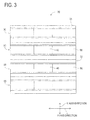
- the conveyance device 88 and the conveyance device 90 are distinguished from each other, the conveyance device (conveyance device located on the lower side in Fig. 3 ) connected to the first conveyance device 22 of the inspection machine 18 out of the pair of conveyance devices 88 and 90 is also referred to as a first conveyance device 88, and the other conveyance device (conveyance device located on the upper side in Fig. 3 ) connected to the second conveyance device 24 of the inspection machine 18 is also referred to as a second conveyance device 90, as illustrated in Fig. 1 .
- Each of the panels 96 and 98 is slidable on the base 94 in the Y axis direction, and the discharging mechanism 92 includes an electromagnetic motor (see Fig. 4 ) 100 for causing the respective panels 96 and 98 to slide in the Y axis direction. Accordingly, the conveyance devices 88 and 90 can be made to slide in the Y axis direction. Specifically, by moving the first conveyance device 88 in the direction in which it is spaced apart from the second conveyance device 90, the first conveyance device 88 moves to the position indicated by a two-dot chain line in Fig. 3 . Accordingly, the circuit substrate 40 supported by the first conveyance device 88 is discharged from the conveyance line.
- the position of the first conveyance device 88 indicated by the two-dot chain line in Fig. 3 is the discharging position of the circuit substrate 40.
- the second conveyance device 90 moves to the position indicated by a two-dot chain line in Fig. 3 .
- the first conveyance device 88 moves to the position at which the second conveyance device 90 is indicated by a solid line in Fig. 3 .
- the first conveyance device 88 is connected to the second conveyance device 24 of the inspection machine 18 as illustrated in Fig. 6 . That is, the position of the second conveyance device 90 indicated by the two-dot chain line in Fig. 3 is a retracted position at which the first conveyance device 88 of the NG substrate discharging machine 20 is connected to the second conveyance device 24 of the inspection machine 18.
- the second conveyance device 90 is moved to the position at which the first conveyance device 88 is indicated by the solid line in Fig. 3 . Accordingly, the second conveyance device 90 is connected to the first conveyance device 22 of the inspection machine 18 as illustrated in Fig. 7 .
- the NG substrate discharging machine 20 includes a signal tower (see Fig. 4 ) 101.
- the signal tower 101 displays the inspection result of the circuit substrate conveyed to the NG substrate discharging machine 20 by emitting light. Specifically, when a circuit substrate of which the inspection result is not good is conveyed to the NG substrate discharging machine 20, the signal tower 101 emits red light.
- the mounting system 10 includes plural individual control devices 102, 104, 106, 108, and 110 disposed to correspond to the mounting machines 12 and 14, the solder printing machine 16, the inspection machine 18, and the NG substrate discharging machine 20.
- the individual control device 108 disposed to correspond to the inspection machine 18 includes a controller 112, an image processing device 114, and plural drive circuits 118.
- the plural drive circuits 118 are connected to the electromagnetic motors 38, 58, and 62 and the substrate support device 42.
- the image processing device 114 is connected to the inspection camera 84, and processes image data acquired by the inspection camera 84.
- the controller 112 is constituted with a computer including a CPU, a ROM, and a RAM as a main body and is connected to the image processing device 114 and the plural drive circuits 118. Accordingly, the operations of the conveyance devices 22 and 24, the moving device 30, and the like are controlled by the controller 112 and it is determined by the controller 112 whether the mounting work of an electronic component on the circuit substrate is good.
- the individual control device 110 disposed to correspond to the NG substrate discharging machine 20 includes a controller 120, a control circuit 121, and plural drive circuits 122.
- the control circuit 121 is connected to the signal tower 101, and the plural drive circuits 122 are connected to the electromagnetic motors 38 and 100 and the substrate support device 42.
- the controller 120 is constituted with a computer including a CPU, a ROM, and a RAM as a main body and is connected to the control circuit 121 and the plural drive circuits 122. Accordingly, the operations of the conveyance devices 88 and 90 and the discharging mechanism 92 and the lighting of the signal tower 101 are controlled by the controller 120.
- the individual control devices 102, 104, and 106 disposed to correspond to the mounting machines 12 and 14 and the solder printing machine 16 include a controller and drive circuits and have a configuration similar to the controller and the drive circuits which have been described above, and detailed description and illustration thereof will not be repeated.
- the controllers 112 and 120 of the plural individual control devices 102, 104, 106, 108 and 110 are connected to each other, and information, commands, and the like are transmitted and received between the controllers 112 and 120.
- circuit substrates are conveyed from the solder printing machine 16 disposed most upstream to the NG substrate discharging machine 20 disposed most downstream.
- the conveyed circuit substrates are subjected to work by the solder printing machine 16 and the mounting machines 12 and 14. It is inspected by the inspection machine 18 whether the work by the working machines is good, and the circuit substrate of which the inspection result is not good is discharged by the NG substrate discharging machine 20.
- the circuit substrates are conveyed to a working position by the first conveyance device 76 and the second conveyance device 78 of the solder printing machine 16, and are supported at the working position by the substrate support device 42. Then, paste solder is printed on the circuit substrates by the printing machine of the solder printing machine 16. Then, the circuit substrates on which the paste solder has been printed are conveyed to the mounting machine 12 by the conveyance devices 76 and 78.
- the circuit substrates conveyed from the solder printing machine 16 to the mounting machine 12 is conveyed to a working position by the first conveyance device 22 and the second conveyance device 24 of the mounting machine 12, and is supported at the working position by the substrate support device 42. Then, the mounting heads 26 and 28 move to supply positions of the supply devices 32 and 34 by the moving device 30. Electronic components fed from the supply devices 32 and 34 are suctioned and supported by the mounting heads 26 and 28. Subsequently, the mounting heads 26 and 28 move onto the circuit substrates by the moving device 30 and the electronic components are mounted on the circuit substrates.
- the circuit substrates on which the electronic components have been mounted are conveyed to the mounting machine 14 by the conveyance devices 22 and 24.
- the same work as in the mounting machine 12 is performed, whereby the mounting work of electronic components on the circuit substrates is completed.
- the circuit substrates on which the mounting work of electronic components has been completed are conveyed to the inspection machine 18 by the conveyance devices 22 and 24 of the mounting machine 14.
- the inspection machine 18 the circuit substrates are conveyed to a working position by the first conveyance device 22 and the second conveyance device 24 of the inspection machine 18, and are supported at the working position by the substrate support device 42.
- the inspection heads 80 and 82 move onto the circuit substrates by the moving device 30, and the circuit substrates are imaged by the inspection camera 84.
- Image data acquired by the inspection camera 84 is processed by the image processing device 114, and information on the mounting state of the electronic components on the circuit substrates is acquired. Inspection work on the circuit substrates on which the electronic components have been mounted is performed on the basis of the information. Then, the circuit substrates subjected to the inspection work are conveyed to the NG substrate discharging machine 20 by the conveyance devices 22 and 24.
- the OK substrate is conveyed downstream by the first conveyance device 88 and the second conveyance device 90 of the NG substrate discharging machine 20, and is discharged from the end of the respective conveyance devices 88 and 90. Accordingly, in the mounting system 10, the circuit substrates are conveyed through two paths and an OK substrate is manufactured in each path.
- NG substrate abnormal circuit substrate
- the NG substrate is discharged to the retracted position by the first conveyance device 88 of the NG substrate discharging machine 20.
- the circuit substrate 40 supported by the first conveyance device 22 of the inspection machine 18 is an OK substrate
- the circuit substrate 40 supported by the second conveyance device 24 is an NG substrate.
- information indicating that the circuit substrate 40 supported by the second conveyance device 24 of the inspection machine 18 is an NG substrate is transmitted from the controller 112 of the inspection machine 18 to the controller 120 of the NG substrate discharging machine 20. That is, information indicating that the NG substrate can be sent to the NG substrate discharging machine 20 by the second conveyance device 24 of the inspection machine 18 is transmitted. Then, the NG substrate discharging machine 20 receives the information and causes the signal tower 101 to emit red light on the basis of the received information. The NG substrate discharging machine 20 moves the first conveyance device 88 of the NG substrate discharging machine 20 through the use of the discharging mechanism 92 so that the NG substrate can retract to the retracted position on the basis of the information.
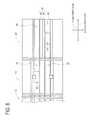
- the second conveyance device 90 in the state illustrated in Fig. 5 is moved in the direction (upward in the drawing) in which it is spaced apart from the first conveyance device 88 by the discharging mechanism 92. Accordingly, the connection between the second conveyance device 90 of the NG substrate discharging machine 20 and the second conveyance device 24 of the inspection machine 18 is released. Then, the first conveyance device 88 is moved to the position of the second conveyance device 90 in the state illustrated in Fig. 5 . Accordingly, the first conveyance device 88 of the NG substrate discharging machine 20 is connected to the second conveyance device 24 of the inspection machine 18 as illustrated in Fig. 6 .
- the second conveyance device 24 of the inspection machine 18 and the first conveyance device 88 of the NG substrate discharging machine 20 are driven and the NG substrate is conveyed to the working position of the first conveyance device 88. Then, at that position, the NG substrate is supported by the substrate support device 42 of the first conveyance device 88.
- the first conveyance device 88 supporting the NG substrate is moved in the direction (downward in the drawing) in which it is spaced apart from the second conveyance device 90, and is moved to the end of the base 94 of the NG substrate discharging machine 20 in the Y axis direction as illustrated in Fig. 7 .
- the position of the end of the base 94 is the retracted position and the NG substrate is discharged to the retracted position by the operation of the discharging mechanism 92.
- an operator In the mounting system 10, an operator generally works on one side (the lower side in the drawing) in the Y axis direction of the mounting system 10, and checking work with eyes, NG substrate removing work, and the like are performed on the NG substrate discharged to the retracted position.
- the second conveyance device 90 of the NG substrate discharging machine 20 is moved in the direction (downward in the drawing) in which it gets close to the first conveyance device 88 so that the OK substrate supported by the first conveyance device 22 of the inspection machine 18 can be discharged from the mounting system 10. Accordingly, the second conveyance device 90 of the NG substrate discharging machine 20 is connected to the first conveyance device 22 of the inspection machine 18. In this state, the first conveyance device 22 of the inspection machine 18 and the second conveyance device 90 of the NG substrate discharging machine 20 are driven and the OK substrate is discharged from the end of the second conveyance device 90.
- the NG substrate is conveyed to the NG substrate discharging machine 20 earlier than the OK substrate in the state in which the OK substrate and the NG substrate can be conveyed from the inspection machine 18 to the NG substrate discharging machine 20.
- the OK substrate is conveyed to the NG substrate discharging machine 20 earlier than the NG substrate in the state in which the OK substrate and the NG substrate can be conveyed from the inspection machine 18 to the NG substrate discharging machine 20.
- the OK substrate supported by the first conveyance device 22 of the inspection machine 18 is conveyed to the first conveyance device 88 of the NG substrate discharging machine 20 as illustrated in Fig.
- the NG substrate is left in a state in which it is supported by the second conveyance device 24 of the inspection machine 18 while the OK substrate is being conveyed. That is, when the OK substrate is conveyed to the NG substrate discharging machine 20 earlier than the NG substrate, the timing of discharging the NG substrate to the retracted position is delayed and the start of work on the NG substrate is delayed.
- the controller 112 of the inspection machine 18 includes a first individual conveyance control unit (see Fig. 4 ) 130 as a functional unit for conveying the NG substrate from the inspection machine 18 to the NG substrate discharging machine 20 earlier than the OK substrate.
- the controller 120 of the NG substrate discharging machine 20 includes a second individual conveyance control unit (see Fig. 4 ) 132 as a functional unit for conveying the NG substrate to the NG substrate discharging machine 20 earlier than the OK substrate.
- the signal tower 101 emits red light on the basis of the information indicating that the NG substrate can be conveyed to the NG substrate discharging machine 20 before the NG substrate is conveyed to the NG substrate discharging machine 20. That is, before the NG substrate is conveyed to the NG substrate discharging machine 20, an operator is notified that the NG substrate is conveyed to the NG substrate discharging machine 20. Accordingly, the operator can prepare for work on the NG substrate or the like and it is thus possible to enhance work efficiency.
- the electronic component mounting system 10 is an example of the work system for substrates.
- the electronic component mounting machines 12 and 14, the solder printing machine 16, the inspection machine 18, and the NG substrate discharging machine 20 are examples of the plural working machines.
- the inspection machine 18 is an example of the upstream working machine and the NG substrate discharging machine 20 is an example of the downstream working machine.
- the conveyance devices, 22, 24, 76, 78, 88, and 90 are examples of the substrate conveyance device.
- the individual conveyance control devices 102, 104, 106, 108, and 110 are examples of the control device.
- the first individual conveyance control unit 130 and the second individual conveyance control unit 132 are examples of the substrate conveyance control unit.
- the signal tower 101 is an example of the alarm device.
- the NG substrate discharging machine 20 is an example of the working machine and the individual control device 110 of the NG substrate discharging machine 20 is an example of the individual control device.
- the inspection machine 18 is employed as the upstream working machine in the aforementioned example, but various working machines may be employed. Specifically, for example, a solder printing machine, a mounting machine, or the like may be employed, or a working machine including only a conveyance device may be employed.
- a circuit substrate on which an electronic component is not appropriately mounted is employed as the NG substrate in the aforementioned example, but a circuit substrate of which various work results are not good may be employed. Specifically, for example, a circuit substrate on which printing or coating work of solder, adhesive, or the like is not appropriately performed may be employed as the NG substrate.
- various commands, a variety of information, and the like are transmitted and received between the individual control devices 102, 104, 106, 108, and 110, but a general control device may be provided and a variety of commands, a variety of information, and the like may be transmitted from the general control device to the plural individual control devices 102, 104, 106, and 108.
- the general control device is provided with a substrate conveyance control unit.
Landscapes
- Engineering & Computer Science (AREA)
- Manufacturing & Machinery (AREA)
- Microelectronics & Electronic Packaging (AREA)
- Operations Research (AREA)
- Mechanical Engineering (AREA)
- Supply And Installment Of Electrical Components (AREA)
- General Factory Administration (AREA)
Abstract
Description
- The present invention relates to a work system for substrates in which a circuit substrate is conveyed from a working machine disposed upstream out of plural working machines to a working machine disposed downstream and a working machine constituting the work system.
- In general, a work system for substrates includes plural working machines arranged in a line. A circuit substrate is conveyed from a working machine disposed upstream out of the plural working machines to a working machine disposed downstream. The plural working machines include a working machine that performs coating work such as paste soldering on a circuit substrate, a working machine that performs mounting work of electronic components on a circuit substrate, and an inspection machine that inspects the work results of a variety of work. In the system, when the inspection result of a circuit substrate inspected by the inspection machine is good, that is, when the circuit substrate inspected by the inspection machine is a normal circuit substrate (hereinafter, also referred to as "OK substrate"), the OK substrate is conveyed downstream through a predetermined path. On the other hand, when the inspection result of the circuit substrate inspected by the inspection machine is not good, that is, when the circuit substrate inspected by the inspection machine is an abnormal circuit substrate (hereinafter, also referred to as "NG substrate"), the NG substrate moves to a retracted position retracting from the predetermined path. An example of the system is described in the following patent literature.
- PTL 1:
JP-A-2007-123503 - In the work system for substrates described in the patent literature, since an NG substrate moves to the retracted position, an operator can perform a variety of work on the NG substrate at that position. On the other hand, as the work system for substrates, a system in which each working machine includes a pair of conveyance devices and a circuit substrate is conveyed by the pair of conveyance devices is known so as to achieve improvement in productivity. That is, a system in which circuit substrates are conveyed through two paths is present. In such a system, when an OK substrate is conveyed through one path of the two paths, an NG substrate in the other path of the two paths may not be moved to the retracted position. In this case, the timing of discharging the NG substrate to the retracted position is delayed and start of work on the NG substrate is delayed. As a result, work efficiency degrades. The present invention is made in consideration of the aforementioned circumstances and an object thereof is to provide a work system for substrates and a working machine with high work efficiency.
- In order to achieve the aforementioned object, according to
claim 1 of the present invention, there is provided a work system for substrates, including: a plurality of working machines that includes a pair of substrate conveyance devices for conveying circuit substrates through two paths and that is arranged in a line; and a control device that controls operations of the pair of substrate conveyance devices of each of the plurality of working machines, in which the circuit substrates are conveyed through the two paths from the working machine disposed upstream out of the plurality of working machines to the working machine disposed downstream, wherein the control device includes a substrate conveyance control unit that controls the operations of the pair of substrate conveyance devices of the upstream working machine and the downstream working machine so that a circuit substrate of which the work result is not good is conveyed to the downstream working machine earlier than a circuit substrate of which the work result is good in a state in which the circuit substrate of which the work result is good and the circuit substrate of which the work result is not good are able to be conveyed to the downstream working machine by the pair of substrate conveyance devices of the upstream working machine. - The work system for substrates according to claim 2 is the work system for substrates according to
claim 1, wherein the downstream working machine has a standby position to which the conveyed circuit substrate of which the work result is not good is able to retract from the two paths. - The work system for substrates according to claim 3 is the work system for substrates according to
claim 1 or 2, further including an alarm device that notifies an operator of conveyance of the circuit substrate of which the work result is not good to the downstream working machine before the circuit substrate of which the work result is not good is conveyed to the downstream working machine in a state in which the circuit substrate of which the work result is not good is able to be conveyed to the downstream working machine. - According to claim 4 of the present invention, there is provided a working machine including: a pair of substrate conveyance devices that conveys circuit substrates through two paths; and an individual control device that controls operations of the pair of substrate conveyance devices, wherein the individual control device includes an individual substrate conveyance control unit that controls the operations of the pair of substrate conveyance devices so that a circuit substrate of which the work result is not good is conveyed to the working machine earlier than a circuit substrate of which the work result is good in a state in which the circuit substrate of which the work result is good and the circuit substrate of which the work result is not good are able to be conveyed to the working machine by a working machine disposed upstream of the working machine.
- In the work system for substrates according to
claim 1, the NG substrate is conveyed to the downstream working machine earlier than the OK substrate in the state in which the OK substrate and the NG substrate are able to be conveyed to the downstream working machine by the upstream working machine. Accordingly, for example, it is possible to rapidly move the NG substrate to the retracted position and thus to rapidly perform work on the NG substrate. As a result, it is possible to enhance work efficiency of the work system for substrates. - In the work system for substrates according to claim 2, the retracted position is formed in the downstream working machine. Accordingly, work can be performed on the NG substrate in the downstream working machine.
- In the work system for substrates according to claim 3, the operator is notified of the conveyance of the NG substrate to the downstream working machine before the NG substrate is conveyed to the downstream working machine. Accordingly, the operator can prepare for work on the NG substrate and it is thus possible to further enhance work efficiency.
- In the working machine according to claim 4, the NG substrate is conveyed to the working machine earlier than the OK substrate in the state in which the OK substrate and the NG substrate are able to be conveyed to the working machine by an upstream working machine. Accordingly, for example, it is possible to rapidly move the NG substrate to the retracted position and thus to rapidly perform work on the NG substrate. As a result, it is possible to enhance work efficiency of the working machine.
-
- [
Fig. 1] Fig. 1 is a diagram schematically illustrating a work system for substrates according to an embodiment of the present invention. - [
Fig. 2] Fig. 2 is a diagram illustrating an electronic component mounting machine of the work system for substrates when viewed from the upper side. - [
Fig. 3] Fig. 3 is a diagram illustrating an NG substrate discharging machine of the work system for substrates when viewed from the upper side. - [
Fig. 4] Fig. 4 is a block diagram illustrating individual control devices of respective working machines constituting the work system for substrates. - [
Fig. 5] Fig. 5 is a diagram illustrating an inspection machine and the NG substrate discharging machine of the work system for substrates when viewed from the upper side. - [
Fig. 6] Fig. 6 is a diagram illustrating the inspection machine and the NG substrate discharging machine when viewed from the upper side when an NG substrate is conveyed from the inspection machine to the NG substrate discharging machine. - [
Fig. 7] Fig. 7 is a diagram illustrating the inspection machine and the NG substrate discharging machine when viewed from the upper side when an NG substrate is moved to a retracted position. - [
Fig. 8] Fig. 8 is a diagram illustrating the inspection machine and the NG substrate discharging machine when viewed from the upper side when an OK substrate is conveyed to the NG substrate discharging machine earlier than an NG substrate. - Hereinafter, examples of the present invention as modes for carrying out the present invention will be described in detail with reference to the accompanying drawings.
-
Fig. 1 illustrates an electronic component mounting system (hereinafter, also abbreviated to "mounting system") 10 as an example of the present invention. Themounting system 10 is a system for mounting an electronic circuit component (hereinafter, also abbreviated to "electronic component") on a circuit substrate. Themounting system 10 includes two electronic component mounting machines (hereinafter, also abbreviated to "mounting machine") 12 and 14 , asolder printing machine 16, aninspection machine 18, and an NGsubstrate discharging machine 20. - Two
mounting machines solder printing machine 16 is disposed on the upstream side of themounting machine 12 disposed upstream out of the twomounting machines inspection machine 18 is disposed on the downstream side of themounting machine 14 disposed downstream out of the twomounting machines substrate discharging machine 20 is disposed downstream of theinspection machine 18. In the description below, the direction in which themounting machines solder printing machine 16, theinspection machine 18, and the NGsubstrate discharging machine 20 are arranged is defined as an X axis direction and the horizontal direction perpendicular to the X axis direction is defined as a Y axis direction. - First, the
mounting machines mounting machines mounting machine 12 will be representatively described. As illustrated inFig. 2 , themounting machine 12 includes a pair ofconveyance devices mounting heads supply devices - The pair of
conveyance devices base 35 so as to be parallel to each other and to extend in the X axis direction. The pair ofconveyance devices conveyance devices conveyer belts 36 extending in the X axis direction and an electromagnetic motor (seeFig. 4 ) 38 circulating theconveyer belts 36. Thecircuit substrate 40 is supported by the pair ofconveyer belts 36 and is conveyed in the X axis direction by the driving of theelectromagnetic motor 38. Each of the pair ofconveyance devices Fig. 4 ) 42. Thesubstrate support device 42 fixedly supports thecircuit substrate 40 supported by theconveyer belts 36 at a predetermined position (position at which thecircuit substrate 40 is illustrated inFig. 2 ). When theconveyance device 22 and theconveyance device 24 are distinguished from each other, one conveyance device (conveyance device located on the lower side inFig. 2 ) out of the pair ofconveyance devices first conveyance device 22, and the other conveyance device (conveyance device located on the upper side inFig. 2 ) is also referred to as asecond conveyance device 24. - The
moving device 30 includes an X axis-direction slide mechanism 50 and a Y axis-direction slide mechanism 52. The Y axis-direction slide mechanism 52 includes a pair of Y axis-direction guide rails 54 extending in the Y axis direction. On the other hand, the X axis-direction slide mechanism 50 includes a pair of X axis-direction guide rails 56 extending in the X axis direction. The pair of X axis-direction guide rails 56 is suspended on the pair of Y axis-direction guide rails 54. The Y axis-direction slide mechanism 52 includes an electromagnetic motor (seeFig. 4 ) 58 and the respective X axis-direction guide rails 56 are moved to an arbitrary position in the Y axis direction by the driving of theelectromagnetic motor 58. Each X axis-direction guide rail 56 supports aslider 60 so as to be movable along its own axis line. The X axis-direction slide mechanism 50 includes an electromagnetic motor (seeFig. 4 ) 62 and thesliders 60 are moved to an arbitrary position in the X axis direction by the driving of theelectromagnetic motor 62. Thesliders 60 are provided with the mounting heads 26 and 28. By this structure, the mounting heads 26 and 28 are moved to an arbitrary position on thebase 35 by the movingdevice 30. The mounting heads 26 and 28 are attached to and detached from thesliders 60 by one touch. Accordingly, as will be described later, the mounting heads can be replaced with other types of working heads such as a dispenser head and an inspection head. - Each of the pair of mounting
heads suction nozzle 70 disposed on the bottom surface thereof. Thesuction nozzle 70 is connected to a positive and negative pressure supply device (not illustrated). Accordingly, thesuction nozzle 70 suctions and supports an electronic component using a negative pressure and detaches the electronic component using a positive pressure. Each of the mounting heads 26 and 28 includes a nozzle lifting device (not illustrated) lifting thesuction nozzle 70 and a nozzle rotating device (not illustrated) causing thesuction nozzle 70 to rotate about an axis line. Accordingly, the position in the vertical direction and a support posture of the electronic component supported by thesuction nozzle 70 are adjusted. - The pair of
supply devices conveyance devices supply devices tape feeder 72. Thetape feeder 72 receives a taped component in a wound state. The taped component is a component in which an electronic component is taped. Thetape feeder 72 sends the taped component through the use of a sending device (not illustrated). Accordingly, thesupply devices supply devices base 35. - The
solder printing machine 16 disposed upstream of the mountingmachine 12 includes conveyance devices (seeFig. 1 ) 76 and 78 having the same structure as theconveyance devices machines conveyance devices solder printing machine 16 prints the paste solder on the circuit substrate and conveys the circuit substrate on which the paste solder has been printed to the mountingmachine 12. When theconveyance device 76 and theconveyance device 78 are distinguished from each other, as illustrated inFig. 1 , the conveyance device connected to thefirst conveyance device 22 of the mountingmachine 12 out of the pair ofconveyance devices first conveyance device 76, and the conveyance device connected to thesecond conveyance device 24 of the mountingmachine 12 is also referred to as asecond conveyance device 78. - In the
inspection machine 18 disposed downstream of the mountingmachine 14, the mounting heads 26 and 28 of the mountingmachines sliders 60 and inspection heads (seeFig. 1 ) 80 and 82 are attached to thesliders 60 instead of the mounting heads 26 and 28. In theinspection machine 18, the pair ofsupply devices base 35. That is, theinspection machine 18 includes a pair ofconveyance devices device 30, and a pair of inspection heads 80 and 82. Each of the inspection heads 80 and 82 includes an inspection camera (seeFig. 4 ) 84, and it is inspected whether the mounting work of electronic components on the circuit substrates is good through the use of imaging with theinspection camera 84. - As illustrated in
Fig. 3 , the NGsubstrate discharging machine 20 disposed downstream of theinspection machine 18 includesconveyance devices conveyance devices machines conveyance devices mechanism 92 interposed therebetween. The dischargingmechanism 92 includes twopanels panels conveyance devices panels conveyance device 88 and theconveyance device 90 are distinguished from each other, the conveyance device (conveyance device located on the lower side inFig. 3 ) connected to thefirst conveyance device 22 of theinspection machine 18 out of the pair ofconveyance devices first conveyance device 88, and the other conveyance device (conveyance device located on the upper side inFig. 3 ) connected to thesecond conveyance device 24 of theinspection machine 18 is also referred to as asecond conveyance device 90, as illustrated inFig. 1 . - Each of the
panels mechanism 92 includes an electromagnetic motor (seeFig. 4 ) 100 for causing therespective panels conveyance devices first conveyance device 88 in the direction in which it is spaced apart from thesecond conveyance device 90, thefirst conveyance device 88 moves to the position indicated by a two-dot chain line inFig. 3 . Accordingly, thecircuit substrate 40 supported by thefirst conveyance device 88 is discharged from the conveyance line. That is, the position of thefirst conveyance device 88 indicated by the two-dot chain line inFig. 3 is the discharging position of thecircuit substrate 40. On the other hand, by moving thesecond conveyance device 90 in the direction in which it is spaced apart from thefirst conveyance device 88, thesecond conveyance device 90 moves to the position indicated by a two-dot chain line inFig. 3 . By moving thefirst conveyance device 88 in the direction in which it gets close to thesecond conveyance device 90 when thesecond conveyance device 90 is being moved to the position indicated by the two-dot chain line in the drawing, thefirst conveyance device 88 moves to the position at which thesecond conveyance device 90 is indicated by a solid line inFig. 3 . Accordingly, thefirst conveyance device 88 is connected to thesecond conveyance device 24 of theinspection machine 18 as illustrated inFig. 6 . That is, the position of thesecond conveyance device 90 indicated by the two-dot chain line inFig. 3 is a retracted position at which thefirst conveyance device 88 of the NGsubstrate discharging machine 20 is connected to thesecond conveyance device 24 of theinspection machine 18. By moving thesecond conveyance device 90 in the direction in which it gets close to thefirst conveyance device 88 when thefirst conveyance device 88 is being moved to the position indicated by the two-dot chain line in the drawing, thesecond conveyance device 90 is moved to the position at which thefirst conveyance device 88 is indicated by the solid line inFig. 3 . Accordingly, thesecond conveyance device 90 is connected to thefirst conveyance device 22 of theinspection machine 18 as illustrated inFig. 7 . - The NG
substrate discharging machine 20 includes a signal tower (seeFig. 4 ) 101. Thesignal tower 101 displays the inspection result of the circuit substrate conveyed to the NGsubstrate discharging machine 20 by emitting light. Specifically, when a circuit substrate of which the inspection result is not good is conveyed to the NGsubstrate discharging machine 20, thesignal tower 101 emits red light. - As illustrated in
Fig. 4 , the mountingsystem 10 includes pluralindividual control devices machines solder printing machine 16, theinspection machine 18, and the NGsubstrate discharging machine 20. Theindividual control device 108 disposed to correspond to theinspection machine 18 includes acontroller 112, animage processing device 114, andplural drive circuits 118. Theplural drive circuits 118 are connected to theelectromagnetic motors substrate support device 42. Theimage processing device 114 is connected to theinspection camera 84, and processes image data acquired by theinspection camera 84. Thecontroller 112 is constituted with a computer including a CPU, a ROM, and a RAM as a main body and is connected to theimage processing device 114 and theplural drive circuits 118. Accordingly, the operations of theconveyance devices device 30, and the like are controlled by thecontroller 112 and it is determined by thecontroller 112 whether the mounting work of an electronic component on the circuit substrate is good. - The
individual control device 110 disposed to correspond to the NGsubstrate discharging machine 20 includes acontroller 120, acontrol circuit 121, andplural drive circuits 122. Thecontrol circuit 121 is connected to thesignal tower 101, and theplural drive circuits 122 are connected to theelectromagnetic motors substrate support device 42. Thecontroller 120 is constituted with a computer including a CPU, a ROM, and a RAM as a main body and is connected to thecontrol circuit 121 and theplural drive circuits 122. Accordingly, the operations of theconveyance devices mechanism 92 and the lighting of thesignal tower 101 are controlled by thecontroller 120. Theindividual control devices machines solder printing machine 16 include a controller and drive circuits and have a configuration similar to the controller and the drive circuits which have been described above, and detailed description and illustration thereof will not be repeated. Thecontrollers individual control devices controllers - In the mounting
system 10 having the aforementioned configuration, circuit substrates are conveyed from thesolder printing machine 16 disposed most upstream to the NGsubstrate discharging machine 20 disposed most downstream. The conveyed circuit substrates are subjected to work by thesolder printing machine 16 and the mountingmachines inspection machine 18 whether the work by the working machines is good, and the circuit substrate of which the inspection result is not good is discharged by the NGsubstrate discharging machine 20. - Specifically, the circuit substrates are conveyed to a working position by the
first conveyance device 76 and thesecond conveyance device 78 of thesolder printing machine 16, and are supported at the working position by thesubstrate support device 42. Then, paste solder is printed on the circuit substrates by the printing machine of thesolder printing machine 16. Then, the circuit substrates on which the paste solder has been printed are conveyed to the mountingmachine 12 by theconveyance devices - The circuit substrates conveyed from the
solder printing machine 16 to the mountingmachine 12 is conveyed to a working position by thefirst conveyance device 22 and thesecond conveyance device 24 of the mountingmachine 12, and is supported at the working position by thesubstrate support device 42. Then, the mounting heads 26 and 28 move to supply positions of thesupply devices device 30. Electronic components fed from thesupply devices device 30 and the electronic components are mounted on the circuit substrates. The circuit substrates on which the electronic components have been mounted are conveyed to the mountingmachine 14 by theconveyance devices - Then, in the mounting
machine 14, the same work as in the mountingmachine 12 is performed, whereby the mounting work of electronic components on the circuit substrates is completed. The circuit substrates on which the mounting work of electronic components has been completed are conveyed to theinspection machine 18 by theconveyance devices machine 14. In theinspection machine 18, the circuit substrates are conveyed to a working position by thefirst conveyance device 22 and thesecond conveyance device 24 of theinspection machine 18, and are supported at the working position by thesubstrate support device 42. Then, the inspection heads 80 and 82 move onto the circuit substrates by the movingdevice 30, and the circuit substrates are imaged by theinspection camera 84. Image data acquired by theinspection camera 84 is processed by theimage processing device 114, and information on the mounting state of the electronic components on the circuit substrates is acquired. Inspection work on the circuit substrates on which the electronic components have been mounted is performed on the basis of the information. Then, the circuit substrates subjected to the inspection work are conveyed to the NGsubstrate discharging machine 20 by theconveyance devices - When the inspection result of a circuit substrate inspected by the
inspection machine 18 is good, that is, when the circuit substrate inspected by theinspection machine 18 is a normal circuit substrate (hereinafter, also referred to as "OK substrate"), the OK substrate is conveyed downstream by thefirst conveyance device 88 and thesecond conveyance device 90 of the NGsubstrate discharging machine 20, and is discharged from the end of therespective conveyance devices system 10, the circuit substrates are conveyed through two paths and an OK substrate is manufactured in each path. - On the other hand, when inspection result of a circuit substrate inspected by the
inspection machine 18 is not good, that is, when the circuit substrate inspected by theinspection machine 18 is an abnormal circuit substrate (hereinafter, also referred to as "NG substrate"), the NG substrate is discharged to the retracted position by thefirst conveyance device 88 of the NGsubstrate discharging machine 20. Specifically, for example, as illustrated inFig. 5 , a case is considered in which twocircuit substrates 40 are supported by the twoconveyance devices inspection machine 18, one of twocircuit substrates 40 is an NG substrate, and the other thereof is an OK substrate. In addition, it is assumed that thecircuit substrate 40 supported by thefirst conveyance device 22 of theinspection machine 18 is an OK substrate and thecircuit substrate 40 supported by thesecond conveyance device 24 is an NG substrate. - In this case, information indicating that the
circuit substrate 40 supported by thesecond conveyance device 24 of theinspection machine 18 is an NG substrate is transmitted from thecontroller 112 of theinspection machine 18 to thecontroller 120 of the NGsubstrate discharging machine 20. That is, information indicating that the NG substrate can be sent to the NGsubstrate discharging machine 20 by thesecond conveyance device 24 of theinspection machine 18 is transmitted. Then, the NGsubstrate discharging machine 20 receives the information and causes thesignal tower 101 to emit red light on the basis of the received information. The NGsubstrate discharging machine 20 moves thefirst conveyance device 88 of the NGsubstrate discharging machine 20 through the use of the dischargingmechanism 92 so that the NG substrate can retract to the retracted position on the basis of the information. - Specifically, the
second conveyance device 90 in the state illustrated inFig. 5 is moved in the direction (upward in the drawing) in which it is spaced apart from thefirst conveyance device 88 by the dischargingmechanism 92. Accordingly, the connection between thesecond conveyance device 90 of the NGsubstrate discharging machine 20 and thesecond conveyance device 24 of theinspection machine 18 is released. Then, thefirst conveyance device 88 is moved to the position of thesecond conveyance device 90 in the state illustrated inFig. 5 . Accordingly, thefirst conveyance device 88 of the NGsubstrate discharging machine 20 is connected to thesecond conveyance device 24 of theinspection machine 18 as illustrated inFig. 6 . In this state, thesecond conveyance device 24 of theinspection machine 18 and thefirst conveyance device 88 of the NGsubstrate discharging machine 20 are driven and the NG substrate is conveyed to the working position of thefirst conveyance device 88. Then, at that position, the NG substrate is supported by thesubstrate support device 42 of thefirst conveyance device 88. - Subsequently, the
first conveyance device 88 supporting the NG substrate is moved in the direction (downward in the drawing) in which it is spaced apart from thesecond conveyance device 90, and is moved to the end of thebase 94 of the NGsubstrate discharging machine 20 in the Y axis direction as illustrated inFig. 7 . The position of the end of thebase 94 is the retracted position and the NG substrate is discharged to the retracted position by the operation of the dischargingmechanism 92. In the mountingsystem 10, an operator generally works on one side (the lower side in the drawing) in the Y axis direction of the mountingsystem 10, and checking work with eyes, NG substrate removing work, and the like are performed on the NG substrate discharged to the retracted position. - As illustrated in
Fig. 7 , thesecond conveyance device 90 of the NGsubstrate discharging machine 20 is moved in the direction (downward in the drawing) in which it gets close to thefirst conveyance device 88 so that the OK substrate supported by thefirst conveyance device 22 of theinspection machine 18 can be discharged from the mountingsystem 10. Accordingly, thesecond conveyance device 90 of the NGsubstrate discharging machine 20 is connected to thefirst conveyance device 22 of theinspection machine 18. In this state, thefirst conveyance device 22 of theinspection machine 18 and thesecond conveyance device 90 of the NGsubstrate discharging machine 20 are driven and the OK substrate is discharged from the end of thesecond conveyance device 90. - In this way, in the mounting
system 10, the NG substrate is conveyed to the NGsubstrate discharging machine 20 earlier than the OK substrate in the state in which the OK substrate and the NG substrate can be conveyed from theinspection machine 18 to the NGsubstrate discharging machine 20. On the other hand, a case will be considered in which the OK substrate is conveyed to the NGsubstrate discharging machine 20 earlier than the NG substrate in the state in which the OK substrate and the NG substrate can be conveyed from theinspection machine 18 to the NGsubstrate discharging machine 20. In this case, the OK substrate supported by thefirst conveyance device 22 of theinspection machine 18 is conveyed to thefirst conveyance device 88 of the NGsubstrate discharging machine 20 as illustrated inFig. 8 and is discharged from the NGsubstrate discharging machine 20 by thefirst conveyance device 88. Accordingly, the NG substrate is left in a state in which it is supported by thesecond conveyance device 24 of theinspection machine 18 while the OK substrate is being conveyed. That is, when the OK substrate is conveyed to the NGsubstrate discharging machine 20 earlier than the NG substrate, the timing of discharging the NG substrate to the retracted position is delayed and the start of work on the NG substrate is delayed. - In this way, in the mounting
system 10, since the NG substrate is conveyed to the NGsubstrate discharging machine 20 earlier than the OK substrate, the NG substrate can be rapidly discharged to the retracted position and the work on the NG substrate by an operator can be rapidly started. Thecontroller 112 of theinspection machine 18 includes a first individual conveyance control unit (seeFig. 4 ) 130 as a functional unit for conveying the NG substrate from theinspection machine 18 to the NGsubstrate discharging machine 20 earlier than the OK substrate. Thecontroller 120 of the NGsubstrate discharging machine 20 includes a second individual conveyance control unit (seeFig. 4 ) 132 as a functional unit for conveying the NG substrate to the NGsubstrate discharging machine 20 earlier than the OK substrate. - In the mounting
system 10, thesignal tower 101 emits red light on the basis of the information indicating that the NG substrate can be conveyed to the NGsubstrate discharging machine 20 before the NG substrate is conveyed to the NGsubstrate discharging machine 20. That is, before the NG substrate is conveyed to the NGsubstrate discharging machine 20, an operator is notified that the NG substrate is conveyed to the NGsubstrate discharging machine 20. Accordingly, the operator can prepare for work on the NG substrate or the like and it is thus possible to enhance work efficiency. - In the aforementioned example, the electronic
component mounting system 10 is an example of the work system for substrates. The electroniccomponent mounting machines solder printing machine 16, theinspection machine 18, and the NGsubstrate discharging machine 20 are examples of the plural working machines. Theinspection machine 18 is an example of the upstream working machine and the NGsubstrate discharging machine 20 is an example of the downstream working machine. The conveyance devices, 22, 24, 76, 78, 88, and 90 are examples of the substrate conveyance device. The individualconveyance control devices conveyance control unit 130 and the second individualconveyance control unit 132 are examples of the substrate conveyance control unit. Thesignal tower 101 is an example of the alarm device. The NGsubstrate discharging machine 20 is an example of the working machine and theindividual control device 110 of the NGsubstrate discharging machine 20 is an example of the individual control device. - The present invention is not limited to the aforementioned example, but can be modified in various forms including various modifications and improvements on the knowledge of those skilled in the art. Specifically, for example, the
inspection machine 18 is employed as the upstream working machine in the aforementioned example, but various working machines may be employed. Specifically, for example, a solder printing machine, a mounting machine, or the like may be employed, or a working machine including only a conveyance device may be employed. - A circuit substrate on which an electronic component is not appropriately mounted is employed as the NG substrate in the aforementioned example, but a circuit substrate of which various work results are not good may be employed. Specifically, for example, a circuit substrate on which printing or coating work of solder, adhesive, or the like is not appropriately performed may be employed as the NG substrate.
- In the aforementioned example, various commands, a variety of information, and the like are transmitted and received between the
individual control devices individual control devices -
- 10: electronic component mounting system (work system for substrates)
- 12: electronic component mounting machine (working machine)
- 14: electronic component mounting machine (working machine)
- 16: solder printing machine (working machine)
- 18: inspection machine (working machine) (upstream working machine)
- 20: NG substrate discharging machine (working machine) (downstream working machine)
- 22: conveyance device (substrate conveyance control)
- 24: conveyance device (substrate conveyance control)
- 76: conveyance device (substrate conveyance control)
- 78: conveyance device (substrate conveyance control)
- 88: conveyance device (substrate conveyance control)
- 90: conveyance device (substrate conveyance control)
- 101: signal tower (alarm device)
- 102: individual control device (control device)
- 104: individual control device (control device)
- 106: individual control device (control device)
- 108: individual control device (control device)
- 110: individual control device (control device)
- 130: first individual conveyance control unit (substrate conveyance control unit)
- 132: second individual conveyance control unit (substrate conveyance control unit) (individual substrate conveyance control unit)
Claims (4)
- A work system for substrates, comprising:a plurality of working machines that includes a pair of substrate conveyance devices for conveying circuit substrates through two paths and that is arranged in a line; anda control device that controls operations of the pair of substrate conveyance devices of each of the plurality of working machines,in which the circuit substrates are conveyed through the two paths from the working machine disposed upstream out of the plurality of working machines to the working machine disposed downstream,wherein the control device includes a substrate conveyance control unit that controls the operations of the pair of substrate conveyance devices of the upstream working machine and the downstream working machine so that a circuit substrate of which the work result is not good is conveyed to the downstream working machine earlier than a circuit substrate of which the work result is good in a state in which the circuit substrate of which the work result is good and the circuit substrate of which the work result is not good are able to be conveyed to the downstream working machine by the pair of substrate conveyance devices of the upstream working machine.
- The work system for substrates according to claim 1, wherein the downstream working machine has a standby position to which the conveyed circuit substrate of which the work result is not good is able to retract from the two paths.
- The work system for substrates according to claim 1 or 2, further comprising an alarm device that notifies an operator of conveyance of the circuit substrate of which the work result is not good to the downstream working machine before the circuit substrate of which the work result is not good is conveyed to the downstream working machine in a state in which the circuit substrate of which the work result is not good is able to be conveyed to the downstream working machine.
- A working machine comprising:a pair of substrate conveyance devices that conveys circuit substrates through two paths; andan individual control device that controls operations of the pair of substrate conveyance devices,wherein the individual control device includes an individual substrate conveyance control unit that controls the operations of the pair of substrate conveyance devices so that a circuit substrate of which the work result is not good is conveyed to the working machine earlier than a circuit substrate of which the work result is good in a state in which the circuit substrate of which the work result is good and the circuit substrate of which the work result is not good are able to be conveyed to the working machine by a working machine disposed upstream of the working machine.
Applications Claiming Priority (1)
| Application Number | Priority Date | Filing Date | Title |
|---|---|---|---|
| PCT/JP2012/068070 WO2014013537A1 (en) | 2012-07-17 | 2012-07-17 | Work system and work machines for substrates |
Publications (3)
| Publication Number | Publication Date |
|---|---|
| EP2876990A1 true EP2876990A1 (en) | 2015-05-27 |
| EP2876990A4 EP2876990A4 (en) | 2015-12-16 |
| EP2876990B1 EP2876990B1 (en) | 2018-10-24 |
Family
ID=49948393
Family Applications (1)
| Application Number | Title | Priority Date | Filing Date |
|---|---|---|---|
| EP12881317.7A Active EP2876990B1 (en) | 2012-07-17 | 2012-07-17 | Work system and work machines for substrates |
Country Status (5)
| Country | Link |
|---|---|
| US (1) | US9346625B2 (en) |
| EP (1) | EP2876990B1 (en) |
| JP (1) | JP6109171B2 (en) |
| CN (1) | CN104472029B (en) |
| WO (1) | WO2014013537A1 (en) |
Families Citing this family (5)
| Publication number | Priority date | Publication date | Assignee | Title |
|---|---|---|---|---|
| WO2014083689A1 (en) * | 2012-11-30 | 2014-06-05 | 富士機械製造株式会社 | Work system for substrate |
| JP6336329B2 (en) * | 2014-05-08 | 2018-06-06 | 株式会社Fuji | Substrate transfer device |
| WO2018207260A1 (en) * | 2017-05-09 | 2018-11-15 | 株式会社Fuji | Substrate working machine |
| JP7029914B2 (en) * | 2017-09-25 | 2022-03-04 | 東京エレクトロン株式会社 | Board processing equipment |
| JP6841927B2 (en) * | 2017-09-26 | 2021-03-10 | 株式会社Fuji | Mounting accuracy measurement system and mounting accuracy measurement method for component mounting line |
Family Cites Families (18)
| Publication number | Priority date | Publication date | Assignee | Title |
|---|---|---|---|---|
| DE3540316A1 (en) * | 1985-11-13 | 1987-05-14 | Siemens Ag | MANUFACTURING SYSTEM FOR AUTOMATIC ASSEMBLY AND TESTING OF ELECTRONIC FLAT ASSEMBLIES |
| US5680936A (en) * | 1995-03-14 | 1997-10-28 | Automated Technologies Industries, Inc. | Printed circuit board sorting device |
| AU2287001A (en) * | 1999-12-21 | 2001-07-03 | Speedline Technologies, Inc. | High speed electronic assembly system and method |
| US7270227B2 (en) * | 2003-10-29 | 2007-09-18 | Lockheed Martin Corporation | Material handling system and method of use |
| US7243777B2 (en) * | 2004-12-17 | 2007-07-17 | Siemens Corporate Research, Inc. | Omega package sorter |
| JP2007123503A (en) | 2005-10-27 | 2007-05-17 | I-Pulse Co Ltd | Inspection conveyance machine, inspection check method and mounting line |
| JP2007147354A (en) * | 2005-11-25 | 2007-06-14 | I-Pulse Co Ltd | Inspection machine, inspection method and mounting line |
| JP4847956B2 (en) * | 2006-01-11 | 2011-12-28 | パナソニック株式会社 | Electronic component mounting system and electronic component mounting method |
| JP2007329365A (en) * | 2006-06-09 | 2007-12-20 | Matsushita Electric Ind Co Ltd | Defective substrate discharge apparatus and defective substrate discharge method |
| CN101953242A (en) * | 2008-02-21 | 2011-01-19 | 松下电器产业株式会社 | Mounting Condition Determination Method |
| JP4858469B2 (en) * | 2008-03-14 | 2012-01-18 | パナソニック株式会社 | Component mounting method |
| JP2010073762A (en) * | 2008-09-17 | 2010-04-02 | Panasonic Corp | Work system and signal transmitting method between work machines |
| JP4883072B2 (en) * | 2008-10-03 | 2012-02-22 | パナソニック株式会社 | Electronic component mounting system |
| US8555784B2 (en) * | 2008-11-19 | 2013-10-15 | Illinois Tool Works Inc. | Method of processing electronic substrates using vertically separated pass through conveyor system |
| JP2010251449A (en) * | 2009-04-14 | 2010-11-04 | Panasonic Corp | Component mounting system and inspection signal transmission method in component mounting system |
| JP5773474B2 (en) * | 2010-05-20 | 2015-09-02 | 富士機械製造株式会社 | Component mounting system |
| JP5590530B2 (en) * | 2010-08-03 | 2014-09-17 | 富士機械製造株式会社 | PCB printing system |
| JP5480776B2 (en) * | 2010-11-02 | 2014-04-23 | ヤマハ発動機株式会社 | Mounting mode determination method and component mounting system |
-
2012
- 2012-07-17 WO PCT/JP2012/068070 patent/WO2014013537A1/en not_active Ceased
- 2012-07-17 US US14/414,928 patent/US9346625B2/en active Active
- 2012-07-17 CN CN201280074764.4A patent/CN104472029B/en active Active
- 2012-07-17 JP JP2014525574A patent/JP6109171B2/en active Active
- 2012-07-17 EP EP12881317.7A patent/EP2876990B1/en active Active
Also Published As
| Publication number | Publication date |
|---|---|
| JP6109171B2 (en) | 2017-04-05 |
| WO2014013537A1 (en) | 2014-01-23 |
| EP2876990B1 (en) | 2018-10-24 |
| US9346625B2 (en) | 2016-05-24 |
| EP2876990A4 (en) | 2015-12-16 |
| CN104472029A (en) | 2015-03-25 |
| US20150223370A1 (en) | 2015-08-06 |
| JPWO2014013537A1 (en) | 2016-06-23 |
| CN104472029B (en) | 2017-06-09 |
Similar Documents
| Publication | Publication Date | Title |
|---|---|---|
| US10888041B2 (en) | Substrate working system and component mounter | |
| EP2876990B1 (en) | Work system and work machines for substrates | |
| US9167701B2 (en) | Method of mounting electronic component | |
| CN103327802B (en) | Apparatus for mounting component and component mounting method | |
| JP6219838B2 (en) | Component mounter | |
| US10863657B2 (en) | Electronic component mounting method | |
| EP2897449B1 (en) | Work system for substrate and workbench-quantity-determining program | |
| JP6232583B2 (en) | Substrate transport method and component mounting apparatus | |
| CN104105392B (en) | Electronic component mounting apparatus | |
| JP6356222B2 (en) | Component mounting device | |
| JPWO2016203533A1 (en) | Mounting management device | |
| CN105960834A (en) | Electronic component mounting device | |
| JP4893696B2 (en) | Electronic component mounting apparatus and board conveying method in electronic component mounting apparatus | |
| EP3089572B1 (en) | Substrate work device | |
| JP2019207967A (en) | Substrate conveyance device, printer, component mounting machine, and substrate conveyance method | |
| JP6148674B2 (en) | Board work system | |
| CN101743787A (en) | Component mounting machine and method of using the same | |
| CN113545184B (en) | Servo amplifier system | |
| JP5855432B2 (en) | Board work system | |
| US10647510B2 (en) | Board work machine and board work system | |
| EP3846604B1 (en) | Control program checking device | |
| JP5970401B2 (en) | MOTOR CONTROL METHOD FOR MOUNTING WORKING DEVICE AND MOUNTING WORKING DEVICE | |
| JP2014183243A (en) | Height detection method for mounting head in electronic component mounting device, and electronic component mounting device |
Legal Events
| Date | Code | Title | Description |
|---|---|---|---|
| PUAI | Public reference made under article 153(3) epc to a published international application that has entered the european phase |
Free format text: ORIGINAL CODE: 0009012 |
|
| 17P | Request for examination filed |
Effective date: 20150113 |
|
| AK | Designated contracting states |
Kind code of ref document: A1 Designated state(s): AL AT BE BG CH CY CZ DE DK EE ES FI FR GB GR HR HU IE IS IT LI LT LU LV MC MK MT NL NO PL PT RO RS SE SI SK SM TR |
|
| AX | Request for extension of the european patent |
Extension state: BA ME |
|
| DAX | Request for extension of the european patent (deleted) | ||
| RA4 | Supplementary search report drawn up and despatched (corrected) |
Effective date: 20151118 |
|
| RIC1 | Information provided on ipc code assigned before grant |
Ipc: H05K 13/00 20060101AFI20151112BHEP Ipc: H05K 13/04 20060101ALI20151112BHEP |
|
| GRAP | Despatch of communication of intention to grant a patent |
Free format text: ORIGINAL CODE: EPIDOSNIGR1 |
|
| STAA | Information on the status of an ep patent application or granted ep patent |
Free format text: STATUS: GRANT OF PATENT IS INTENDED |
|
| INTG | Intention to grant announced |
Effective date: 20171221 |
|
| GRAJ | Information related to disapproval of communication of intention to grant by the applicant or resumption of examination proceedings by the epo deleted |
Free format text: ORIGINAL CODE: EPIDOSDIGR1 |
|
| STAA | Information on the status of an ep patent application or granted ep patent |
Free format text: STATUS: REQUEST FOR EXAMINATION WAS MADE |
|
| INTC | Intention to grant announced (deleted) | ||
| GRAJ | Information related to disapproval of communication of intention to grant by the applicant or resumption of examination proceedings by the epo deleted |
Free format text: ORIGINAL CODE: EPIDOSDIGR1 |
|
| STAA | Information on the status of an ep patent application or granted ep patent |
Free format text: STATUS: GRANT OF PATENT IS INTENDED |
|
| GRAP | Despatch of communication of intention to grant a patent |
Free format text: ORIGINAL CODE: EPIDOSNIGR1 |
|
| INTG | Intention to grant announced |
Effective date: 20180622 |
|
| GRAS | Grant fee paid |
Free format text: ORIGINAL CODE: EPIDOSNIGR3 |
|
| GRAA | (expected) grant |
Free format text: ORIGINAL CODE: 0009210 |
|
| STAA | Information on the status of an ep patent application or granted ep patent |
Free format text: STATUS: THE PATENT HAS BEEN GRANTED |
|
| AK | Designated contracting states |
Kind code of ref document: B1 Designated state(s): AL AT BE BG CH CY CZ DE DK EE ES FI FR GB GR HR HU IE IS IT LI LT LU LV MC MK MT NL NO PL PT RO RS SE SI SK SM TR |
|
| RAP1 | Party data changed (applicant data changed or rights of an application transferred) |
Owner name: FUJI CORPORATION |
|
| REG | Reference to a national code |
Ref country code: CH Ref legal event code: EP |
|
| REG | Reference to a national code |
Ref country code: IE Ref legal event code: FG4D |
|
| REG | Reference to a national code |
Ref country code: AT Ref legal event code: REF Ref document number: 1058264 Country of ref document: AT Kind code of ref document: T Effective date: 20181115 |
|
| REG | Reference to a national code |
Ref country code: DE Ref legal event code: R096 Ref document number: 602012052754 Country of ref document: DE |
|
| REG | Reference to a national code |
Ref country code: NL Ref legal event code: FP |
|
| REG | Reference to a national code |
Ref country code: CH Ref legal event code: PK Free format text: BERICHTIGUNGEN |
|
| RIN2 | Information on inventor provided after grant (corrected) |
Inventor name: SUZUKI, JUNICHI |
|
| REG | Reference to a national code |
Ref country code: LT Ref legal event code: MG4D |
|
| REG | Reference to a national code |
Ref country code: AT Ref legal event code: MK05 Ref document number: 1058264 Country of ref document: AT Kind code of ref document: T Effective date: 20181024 |
|
| PG25 | Lapsed in a contracting state [announced via postgrant information from national office to epo] |
Ref country code: LV Free format text: LAPSE BECAUSE OF FAILURE TO SUBMIT A TRANSLATION OF THE DESCRIPTION OR TO PAY THE FEE WITHIN THE PRESCRIBED TIME-LIMIT Effective date: 20181024 Ref country code: FI Free format text: LAPSE BECAUSE OF FAILURE TO SUBMIT A TRANSLATION OF THE DESCRIPTION OR TO PAY THE FEE WITHIN THE PRESCRIBED TIME-LIMIT Effective date: 20181024 Ref country code: LT Free format text: LAPSE BECAUSE OF FAILURE TO SUBMIT A TRANSLATION OF THE DESCRIPTION OR TO PAY THE FEE WITHIN THE PRESCRIBED TIME-LIMIT Effective date: 20181024 Ref country code: NO Free format text: LAPSE BECAUSE OF FAILURE TO SUBMIT A TRANSLATION OF THE DESCRIPTION OR TO PAY THE FEE WITHIN THE PRESCRIBED TIME-LIMIT Effective date: 20190124 Ref country code: AT Free format text: LAPSE BECAUSE OF FAILURE TO SUBMIT A TRANSLATION OF THE DESCRIPTION OR TO PAY THE FEE WITHIN THE PRESCRIBED TIME-LIMIT Effective date: 20181024 Ref country code: BG Free format text: LAPSE BECAUSE OF FAILURE TO SUBMIT A TRANSLATION OF THE DESCRIPTION OR TO PAY THE FEE WITHIN THE PRESCRIBED TIME-LIMIT Effective date: 20190124 Ref country code: HR Free format text: LAPSE BECAUSE OF FAILURE TO SUBMIT A TRANSLATION OF THE DESCRIPTION OR TO PAY THE FEE WITHIN THE PRESCRIBED TIME-LIMIT Effective date: 20181024 Ref country code: PL Free format text: LAPSE BECAUSE OF FAILURE TO SUBMIT A TRANSLATION OF THE DESCRIPTION OR TO PAY THE FEE WITHIN THE PRESCRIBED TIME-LIMIT Effective date: 20181024 Ref country code: ES Free format text: LAPSE BECAUSE OF FAILURE TO SUBMIT A TRANSLATION OF THE DESCRIPTION OR TO PAY THE FEE WITHIN THE PRESCRIBED TIME-LIMIT Effective date: 20181024 Ref country code: IS Free format text: LAPSE BECAUSE OF FAILURE TO SUBMIT A TRANSLATION OF THE DESCRIPTION OR TO PAY THE FEE WITHIN THE PRESCRIBED TIME-LIMIT Effective date: 20190224 |
|
| PG25 | Lapsed in a contracting state [announced via postgrant information from national office to epo] |
Ref country code: GR Free format text: LAPSE BECAUSE OF FAILURE TO SUBMIT A TRANSLATION OF THE DESCRIPTION OR TO PAY THE FEE WITHIN THE PRESCRIBED TIME-LIMIT Effective date: 20190125 Ref country code: PT Free format text: LAPSE BECAUSE OF FAILURE TO SUBMIT A TRANSLATION OF THE DESCRIPTION OR TO PAY THE FEE WITHIN THE PRESCRIBED TIME-LIMIT Effective date: 20190224 Ref country code: RS Free format text: LAPSE BECAUSE OF FAILURE TO SUBMIT A TRANSLATION OF THE DESCRIPTION OR TO PAY THE FEE WITHIN THE PRESCRIBED TIME-LIMIT Effective date: 20181024 Ref country code: SE Free format text: LAPSE BECAUSE OF FAILURE TO SUBMIT A TRANSLATION OF THE DESCRIPTION OR TO PAY THE FEE WITHIN THE PRESCRIBED TIME-LIMIT Effective date: 20181024 Ref country code: AL Free format text: LAPSE BECAUSE OF FAILURE TO SUBMIT A TRANSLATION OF THE DESCRIPTION OR TO PAY THE FEE WITHIN THE PRESCRIBED TIME-LIMIT Effective date: 20181024 |
|
| REG | Reference to a national code |
Ref country code: DE Ref legal event code: R097 Ref document number: 602012052754 Country of ref document: DE |
|
| PG25 | Lapsed in a contracting state [announced via postgrant information from national office to epo] |
Ref country code: CZ Free format text: LAPSE BECAUSE OF FAILURE TO SUBMIT A TRANSLATION OF THE DESCRIPTION OR TO PAY THE FEE WITHIN THE PRESCRIBED TIME-LIMIT Effective date: 20181024 Ref country code: DK Free format text: LAPSE BECAUSE OF FAILURE TO SUBMIT A TRANSLATION OF THE DESCRIPTION OR TO PAY THE FEE WITHIN THE PRESCRIBED TIME-LIMIT Effective date: 20181024 |
|
| PG25 | Lapsed in a contracting state [announced via postgrant information from national office to epo] |
Ref country code: SM Free format text: LAPSE BECAUSE OF FAILURE TO SUBMIT A TRANSLATION OF THE DESCRIPTION OR TO PAY THE FEE WITHIN THE PRESCRIBED TIME-LIMIT Effective date: 20181024 Ref country code: EE Free format text: LAPSE BECAUSE OF FAILURE TO SUBMIT A TRANSLATION OF THE DESCRIPTION OR TO PAY THE FEE WITHIN THE PRESCRIBED TIME-LIMIT Effective date: 20181024 Ref country code: SK Free format text: LAPSE BECAUSE OF FAILURE TO SUBMIT A TRANSLATION OF THE DESCRIPTION OR TO PAY THE FEE WITHIN THE PRESCRIBED TIME-LIMIT Effective date: 20181024 Ref country code: RO Free format text: LAPSE BECAUSE OF FAILURE TO SUBMIT A TRANSLATION OF THE DESCRIPTION OR TO PAY THE FEE WITHIN THE PRESCRIBED TIME-LIMIT Effective date: 20181024 |
|
| PLBE | No opposition filed within time limit |
Free format text: ORIGINAL CODE: 0009261 |
|
| STAA | Information on the status of an ep patent application or granted ep patent |
Free format text: STATUS: NO OPPOSITION FILED WITHIN TIME LIMIT |
|
| 26N | No opposition filed |
Effective date: 20190725 |
|
| PG25 | Lapsed in a contracting state [announced via postgrant information from national office to epo] |
Ref country code: SI Free format text: LAPSE BECAUSE OF FAILURE TO SUBMIT A TRANSLATION OF THE DESCRIPTION OR TO PAY THE FEE WITHIN THE PRESCRIBED TIME-LIMIT Effective date: 20181024 |
|
| PG25 | Lapsed in a contracting state [announced via postgrant information from national office to epo] |
Ref country code: MC Free format text: LAPSE BECAUSE OF FAILURE TO SUBMIT A TRANSLATION OF THE DESCRIPTION OR TO PAY THE FEE WITHIN THE PRESCRIBED TIME-LIMIT Effective date: 20181024 |
|
| REG | Reference to a national code |
Ref country code: CH Ref legal event code: PL |
|
| GBPC | Gb: european patent ceased through non-payment of renewal fee |
Effective date: 20190717 |
|
| PG25 | Lapsed in a contracting state [announced via postgrant information from national office to epo] |
Ref country code: TR Free format text: LAPSE BECAUSE OF FAILURE TO SUBMIT A TRANSLATION OF THE DESCRIPTION OR TO PAY THE FEE WITHIN THE PRESCRIBED TIME-LIMIT Effective date: 20181024 |
|
| REG | Reference to a national code |
Ref country code: BE Ref legal event code: MM Effective date: 20190731 |
|
| PG25 | Lapsed in a contracting state [announced via postgrant information from national office to epo] |
Ref country code: GB Free format text: LAPSE BECAUSE OF NON-PAYMENT OF DUE FEES Effective date: 20190717 |
|
| PG25 | Lapsed in a contracting state [announced via postgrant information from national office to epo] |
Ref country code: BE Free format text: LAPSE BECAUSE OF NON-PAYMENT OF DUE FEES Effective date: 20190731 Ref country code: LU Free format text: LAPSE BECAUSE OF NON-PAYMENT OF DUE FEES Effective date: 20190717 Ref country code: LI Free format text: LAPSE BECAUSE OF NON-PAYMENT OF DUE FEES Effective date: 20190731 Ref country code: CH Free format text: LAPSE BECAUSE OF NON-PAYMENT OF DUE FEES Effective date: 20190731 |
|
| PG25 | Lapsed in a contracting state [announced via postgrant information from national office to epo] |
Ref country code: IE Free format text: LAPSE BECAUSE OF NON-PAYMENT OF DUE FEES Effective date: 20190717 |
|
| PG25 | Lapsed in a contracting state [announced via postgrant information from national office to epo] |
Ref country code: CY Free format text: LAPSE BECAUSE OF FAILURE TO SUBMIT A TRANSLATION OF THE DESCRIPTION OR TO PAY THE FEE WITHIN THE PRESCRIBED TIME-LIMIT Effective date: 20181024 |
|
| PG25 | Lapsed in a contracting state [announced via postgrant information from national office to epo] |
Ref country code: MT Free format text: LAPSE BECAUSE OF FAILURE TO SUBMIT A TRANSLATION OF THE DESCRIPTION OR TO PAY THE FEE WITHIN THE PRESCRIBED TIME-LIMIT Effective date: 20181024 Ref country code: HU Free format text: LAPSE BECAUSE OF FAILURE TO SUBMIT A TRANSLATION OF THE DESCRIPTION OR TO PAY THE FEE WITHIN THE PRESCRIBED TIME-LIMIT; INVALID AB INITIO Effective date: 20120717 |
|
| PG25 | Lapsed in a contracting state [announced via postgrant information from national office to epo] |
Ref country code: MK Free format text: LAPSE BECAUSE OF FAILURE TO SUBMIT A TRANSLATION OF THE DESCRIPTION OR TO PAY THE FEE WITHIN THE PRESCRIBED TIME-LIMIT Effective date: 20181024 |
|
| P01 | Opt-out of the competence of the unified patent court (upc) registered |
Effective date: 20230328 |
|
| PGFP | Annual fee paid to national office [announced via postgrant information from national office to epo] |
Ref country code: NL Payment date: 20250613 Year of fee payment: 14 |
|
| PGFP | Annual fee paid to national office [announced via postgrant information from national office to epo] |
Ref country code: FR Payment date: 20250610 Year of fee payment: 14 |
|
| PGFP | Annual fee paid to national office [announced via postgrant information from national office to epo] |
Ref country code: DE Payment date: 20250528 Year of fee payment: 14 |
|
| PGFP | Annual fee paid to national office [announced via postgrant information from national office to epo] |
Ref country code: IT Payment date: 20250623 Year of fee payment: 14 |